Abstract
The present study deals with the innovation and the possibilities of improving the design solution of a frame connection for two selected types of fasteners. All specimens were made of glued laminated timber. Dowel-type mechanical fasteners, a combination of bolts and dowels, and full-threaded screws were used for the connection. The main goal of this research was to replace the typical solution (common dowel-type fasteners) with a more modern, faster, and easier solution in order to improve the load-carrying capacity, ductility, and deformation capacity of this type of frame connection. This article also aimed to provide a detailed evaluation of the mechanical properties of the used glued laminated timber and fasteners in order to comprehensively evaluate the research task. For the design solution, a frame connection created from a system of two struts and a partition was chosen as the basis of the experimental program. Dowel-type mechanical fasteners, as well as combinations of bolts and dowels, were used for the connection; however, in addition to these standardly used mechanical fasteners, full-threaded screws were used. The article describes the use of static destructive testing to determine the ductility of the connection, considering different variations in the strengthening of the individual segments of the mentioned connection means. In the first variation, the individual components of the frame were not reinforced in any way. In the second, the crossbar was reinforced with two full-threaded bolts. In the third, the webs and the crossbar were reinforced with two full-threaded bolts. In the article, these ductility values were compared with each other and the procedure was set by the currently valid standard.
Keywords:
ductility; load capacity; timber; frame connection; screws; bolts and dowels; glued-laminated timber 1. Introduction
Timber is an important building material for the sustainability of the construction industry. The diagnostics of existing structures is related to the testing of their mechanical properties [1]. The current possibilities of timber processing also allow the design of multistory buildings [2] or long-span structures [3], where it is necessary to respect the experience gained from previous accidents and structural failures [4]. For timber and timber structures, the use of experimental tests of structural details [5,6] or structural parts, e.g., whole frames [7], is very important. For example, the use of numerical modeling based on the finite element method is also very important [8,9]. Interesting and important recent experiments were also presented in [10].
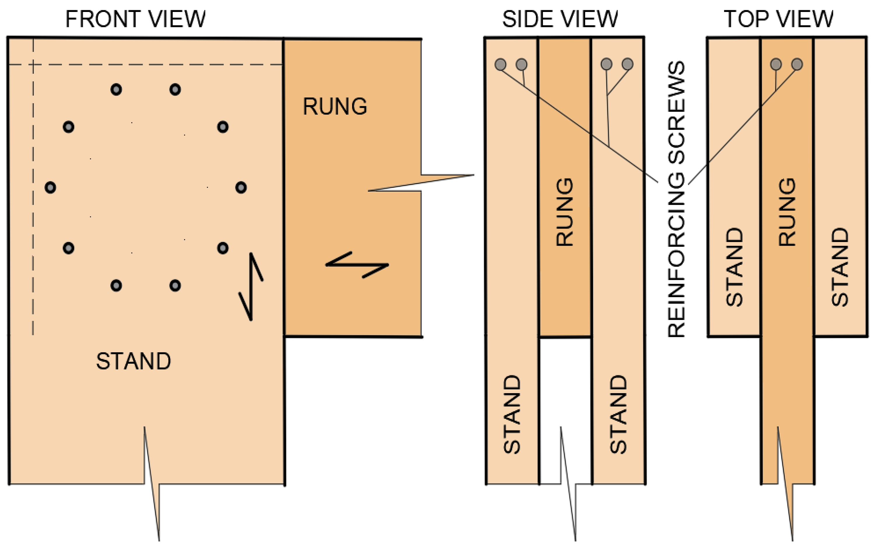
The ductility of the connection is also an important requirement in the design of structures. Eurocode 5 [11] requires a ductile redistribution of internal forces in the joint. Unfortunately, there is not a sufficient specified ductility at which there would be no premature splitting of the connection, i.e., collapse. Ductility can be understood as the ability to achieve large deformations without incurring a significant loss of load-bearing capacity and damage, such as a connection or structural element. This property is difficult to achieve without reinforcement, especially when the timber elements are loaded by bending, tension, or shearing. Large deformations can only be achieved in timber elements under compressive loads. In addition to large deformations of timber elements, large deformations can also occur in connections. A typical example would be a connection with one slim fastener, provided that the connection is properly designed against brittle failure. It is important to note that the redistribution of internal forces due to ductility is related to the depressed zone of the timber. Timber is broken by brittle failure under tension; hence, the plasticization of timber under bending requires significantly higher tensile strength than compressive strength. This would be the case for pure timber mass, but structural timber has imperfections such as knots; thus, the plastic effect is difficult to achieve. This is only possible if the timber defects are only in the pressure zone. A suitable means of achieving said plasticization is the use of reinforcement. For connections in which it is not possible to achieve the required level of ductility of the connection, various methods of reinforcement against brittle failure by shear or tension perpendicular to the grain have been proposed. It is possible to use construction screws, steel sleeves, glued rods, and the like. In the case of a frame connection, it is possible to use designed reinforcement with full-threaded screws located according to Figure 1.
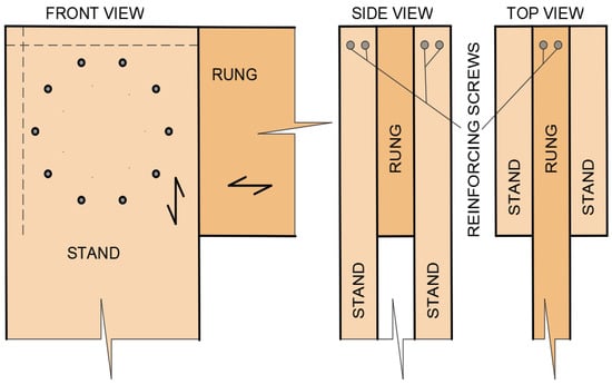
Figure 1.
Reinforcement of the frame connection from the point of view of increasing the ductility of the connection.
Many scientists are trying to identify design connections with high ductility. These connections are not prone to unexpected brittle failure [12]; furthermore, due to their deformation capacity, they allow the required redistribution of internal forces within a static system. In the currently valid standard EN 12512 [13] in Europe, the method of calculating the ductility of the connection is based on the work of Kawai (1998) [14]. Karacabeyli and Ceccotti (1998) [15] characterized the acquisition of connection ductility using a relatively simple method, which differs from the currently valid standard. Stehn and Johansson (2002) [16] performed experiments, on the basis of which a model describing the ductility of the connection was proposed. They defined it as the ratio between finite and elastic deformation. The descriptive model of ductility was compared with the plastic theory of the European Yield Model (EYM), i.e., the standard. Ductility was also addressed by Smith (2006) [17], who established an approach for classifying connections on the basis of ductility, according to the ratio between yield stress and ultimate stress. Muñoz (2008) [18] distinguished between relative and absolute definitions, which could be based on either deformation or energy. Jorissen and Fragiacomo (2011) [19] presented their results in an article where they tested a simple statically indeterminate structure with different reinforcements for the full development of plastic connections. These results were obtained by way of energy dissipation under cyclic loading. Malo (2011) [20] published a procedure for characterizing the response of components. The procedure was based on the separate processing of linear and plastic deformation. Each type of deformation was presented by analytical relations obtained by regression. Blaß and Schädle (2011) [21] published an article comparing the ductility of reinforced and nonreinforced connections with metallic mechanical fasteners. In his experiments, Brühl (2011) [22] investigated the influence of deformation properties and ductility on the redistribution of internal forces of a tensile connection loaded parallel to the grain. In this work, the correct placement of the reinforcing screws proved to be advantageous, and the distance between the connecting means was a suitable advantage. Brühl (2014) [23] extensively presented various findings dealing with the calculation of connection ductility according to different approaches. Additional studies involved in reinforcing the link against brittle breaches and establishing ductility were presented in [24,25,26].
The serviceability, capacity, and durability of the structures depend not only on the surrounding environmental conditions, but also on the execution quality of individual connections between elements [27].
For example, screws, bolts, and dowels are some of the most popular fasteners in timber constructions. They are easy to use, cheap, and affordable everywhere. In order to effectively apply dowel-type connections, it is crucial to understand their mechanical behavior under load, such as the relationship between load and deformation, stress distribution, or failure mode. The mechanical behavior of the connections of timber structures is a complex problem that affects a number of factors. Connection geometry (the spacings between fasteners, edges, and end distances) [28], [29] material characteristics (timber species) [30], and the method of loading are the most important factors.
The present study is devoted to the experimental determination of the ductility of a semirigid connection in which different variations of the reinforcement of individual segments of the structure were used. The study of the frame connection was performed in experiment A using a combination of bolts and dowels and in experiment B using high-strength full-threaded bolts. The fasteners used in experiment A are commonly used in practice, representing a standard combination. Knowledge of the design of such a frame connection can be found in the literature [31]. However, in experiment B, coupling agents were used, which is not common in practice. The presented article is the follow-up of a previous study [32].
2. Materials and Methods
2.1. Description of Construction, Materials, and Geometry
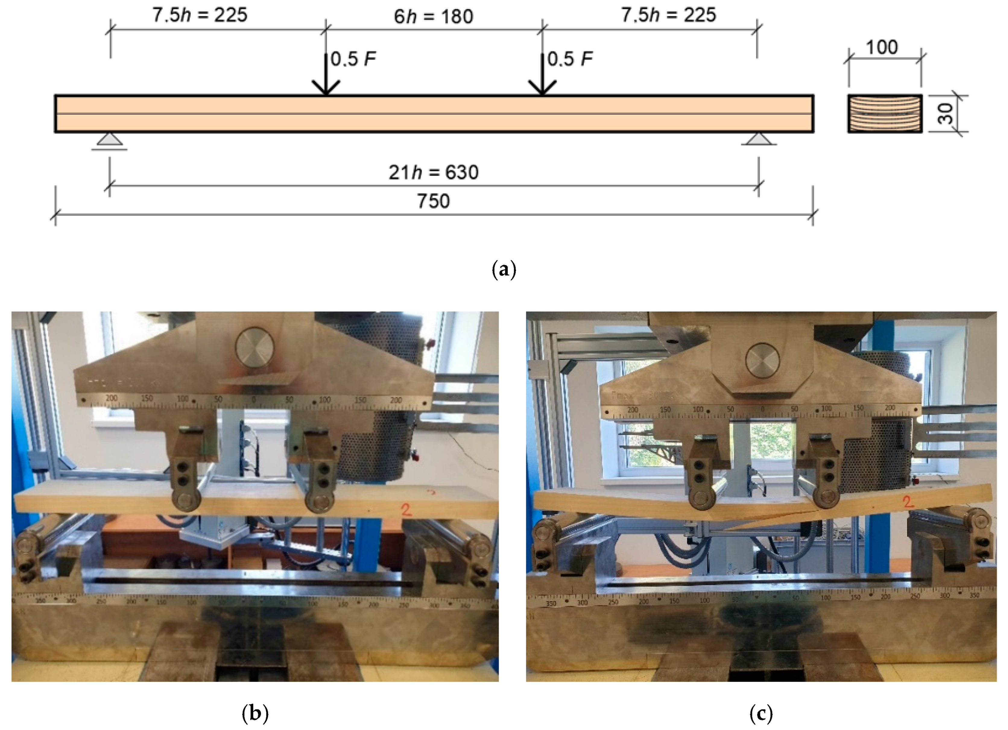
The arrangement and loading of the test specimens and experiments were designed to correspond to the actual state of the connection in a real load-bearing structure. Timber with strength grade GL24h was used for the experiments. These mechanical properties were confirmed by a four-point flexural strength test (Figure 2). A total of 18 planks were cut from the damaged experiments of structures (frame connection) after testing. The nominal dimensions of the specimen were as follows: length, 750 mm; width, 100 mm; height, 30 mm. The specimen was placed on a support with a span of 630 mm and a distance of the applied force from the support on both sides of 225 mm. The loading was performed with a force value of 1.50 kN/min. Table 1 shows the results of the four-point flexural strength test.
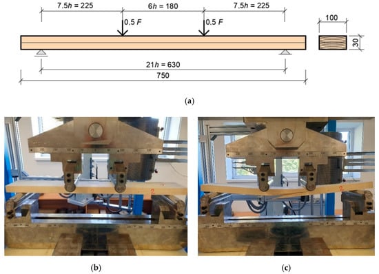
Figure 2.
Four-point flexural strength test: (a) test scheme; (b) before test; and (c) after test.

Table 1.
Results of the four-point flexural strength test (GL24h).
The nomenclature and units are in accordance with the standard EN 384 [33]: fm flexural strength (MPa); fk characteristic value of flexural strength (MPa); f05 5% flexural strength quantile from tested selection (MPa); kn factor taking into account the number of selections and their size (-); kv factor taking into account the lower variability of machine-sorted wood (-); kh height conversion factor, reference height 150 mm (-); ρm measured average wood density of tested samples (kg/m3); kn, kv, kh are non-unit parameters specified by standard EN 384 [33]. The max and min values represent the maximum and minimum values of the achieved flexural strength of the individual tested specimens for the four-point flexural strength. A total of 18 samples were tested, from which the standard deviation and coefficient of variation were calculated.
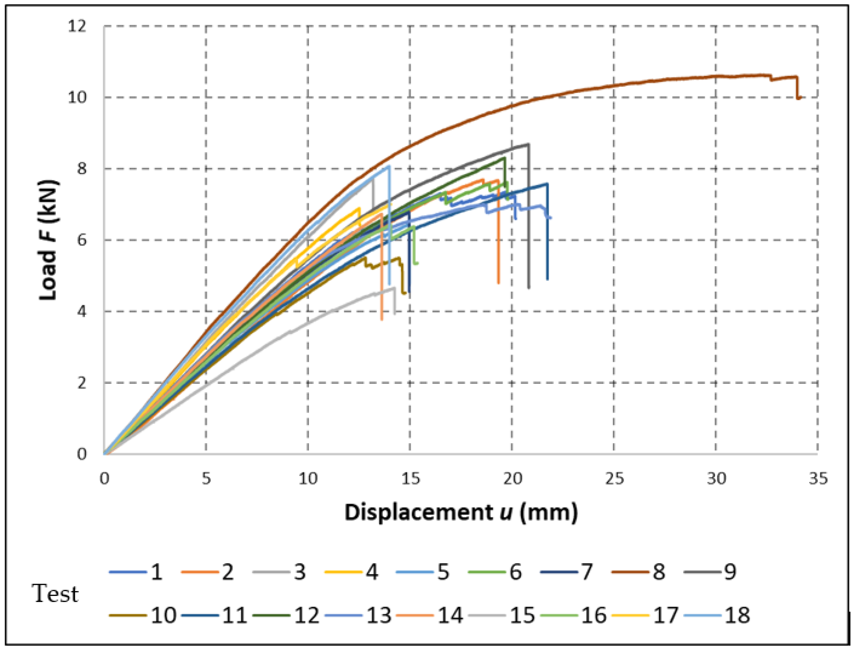
Figure 3 shows the individual load–displacement diagrams of the specimens during the four-point flexural strength test.
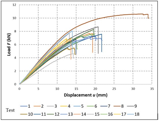
Figure 3.
Load–displacement diagrams of individual specimens of the four-point flexural test.
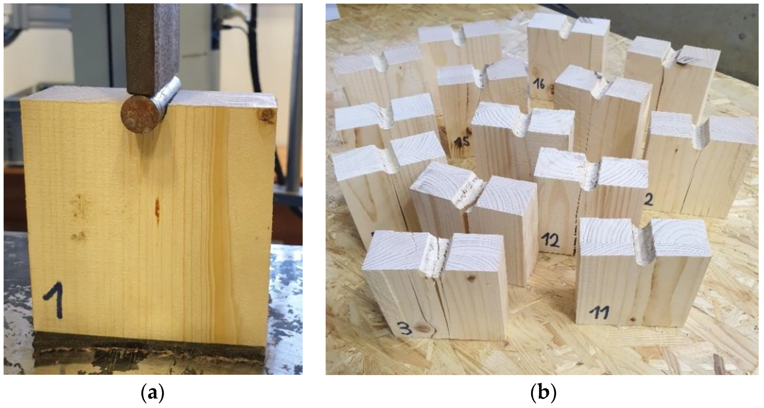
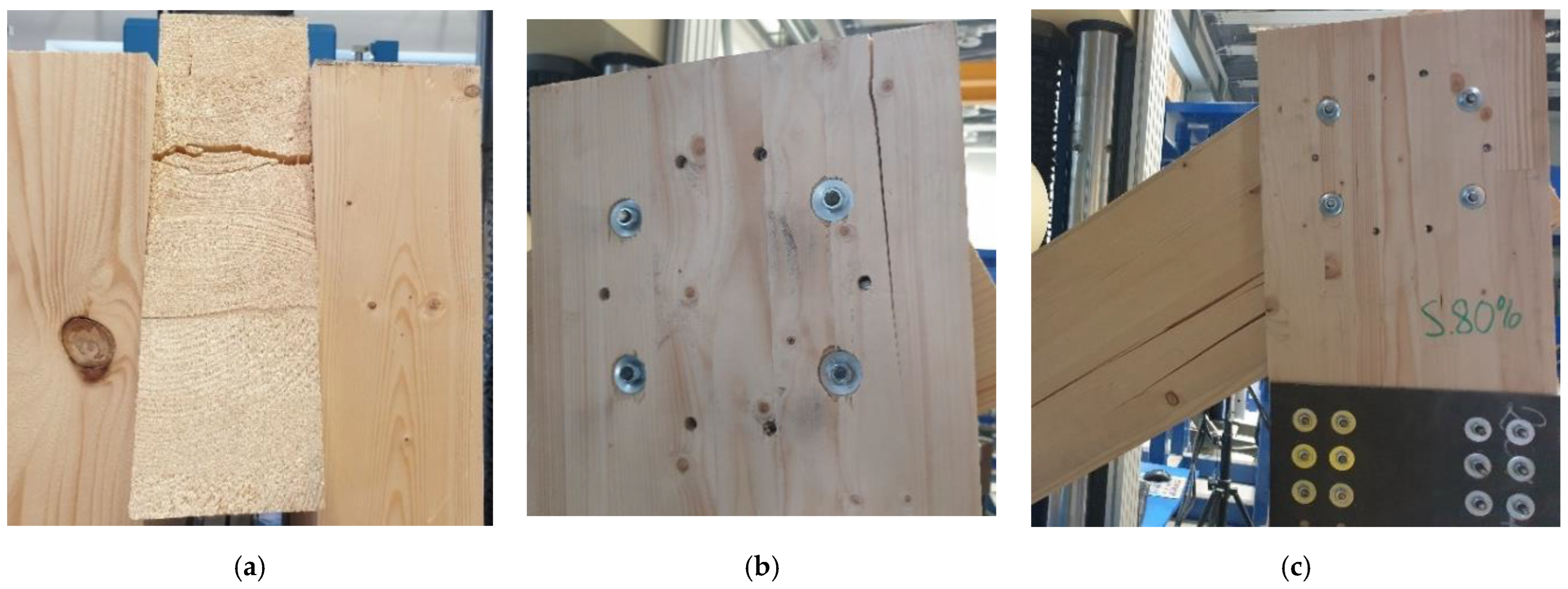
Another laboratory test of timber properties involved the determination of embedment strength and compressibility characteristics for dowel fasteners (Figure 4). This test also confirmed the strength class of the timber. A total of 14 such tests were performed. The nominal size of the specimen was 80 mm wide, 80 mm high, and 40 mm thick. A 16 mm diameter hole was drilled in the specimens and loaded with a 14 mm diameter dowel. The load was chosen to be deformed with a set value of 1 mm/min. The test procedure was performed according to EN 383 [34].

Figure 4.
Laboratory test of determination of hole wall strength and compressibility characteristics for dowel fasteners: (a) test sample during the test, (b) test samples after the test.
Figure 5 shows the individual load–displacement diagrams of the individual specimens during tests for the timber hole wall strength and compressibility characteristics for dowel fasteners.
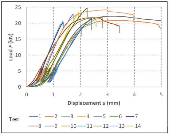
Figure 5.
Results of laboratory tests for the determination of hole wall strength and compressibility characteristics for dowel fasteners.
Almost all specimens (12 specimens) were broken by splitting during testing. Testing of two specimens was completed at a deformation value of 5 mm. The test results are shown in Table 2. Accordingly, it was possible to verify the actual value of the embedment strength of the timber. The table also contains the value obtained using Eurocode 5 [11] in the first column. This value is important for the correct design of each connection of timber structures.
Table 2.
Results of the laboratory tests for the determination of hole wall strength and compressibility characteristics for dowel fasteners.
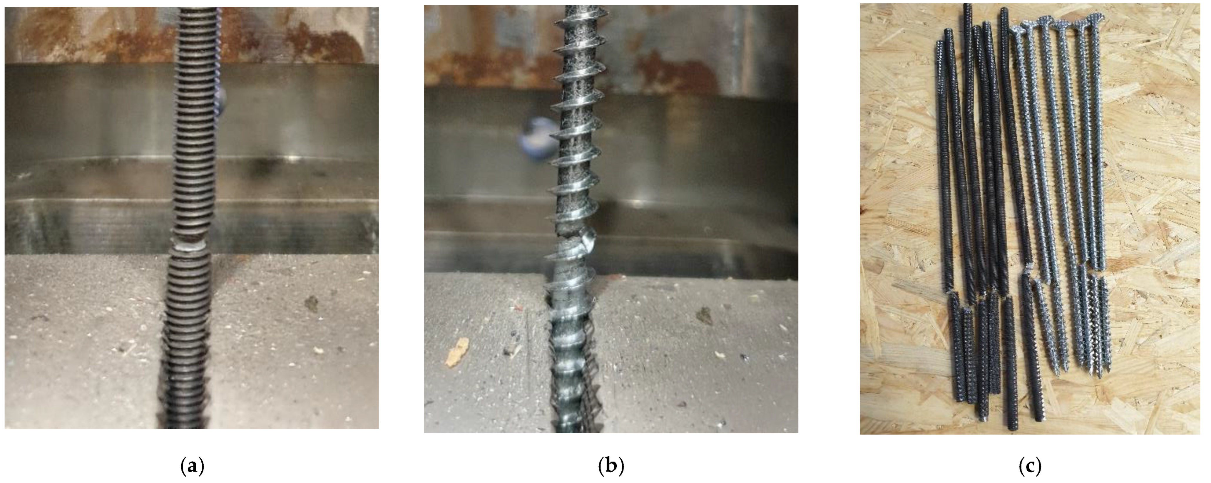
Two types of fasteners were used to make the connection. The first type was a threaded rod. The outer diameter of the threaded rod was 8 mm, and the core diameter was 7.25 mm. The length of the threaded rod 360 mm served as a bolt, and the length of 300 mm served as a dowel in the connection. The second type was a full-threaded screw. The outer diameter of the screw was 8 mm, and the diameter of the screw core was 5 mm. The length of the screws was 300 mm. The mechanical properties of the fasteners were also verified by laboratory tensile strength test (Figure 6). The results obtained by the tear tests are shown in Table 3.
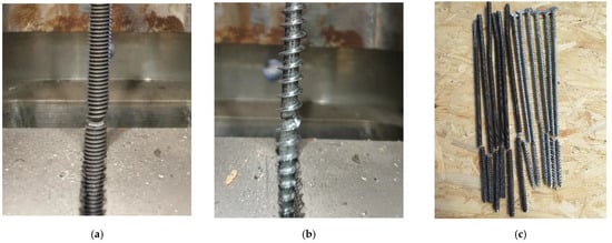
Figure 6.
Tension test: (a) threaded rod; (b) full thread screw; and (c) test specimens.
Table 3.
Evaluation of the tension test of fasteners.
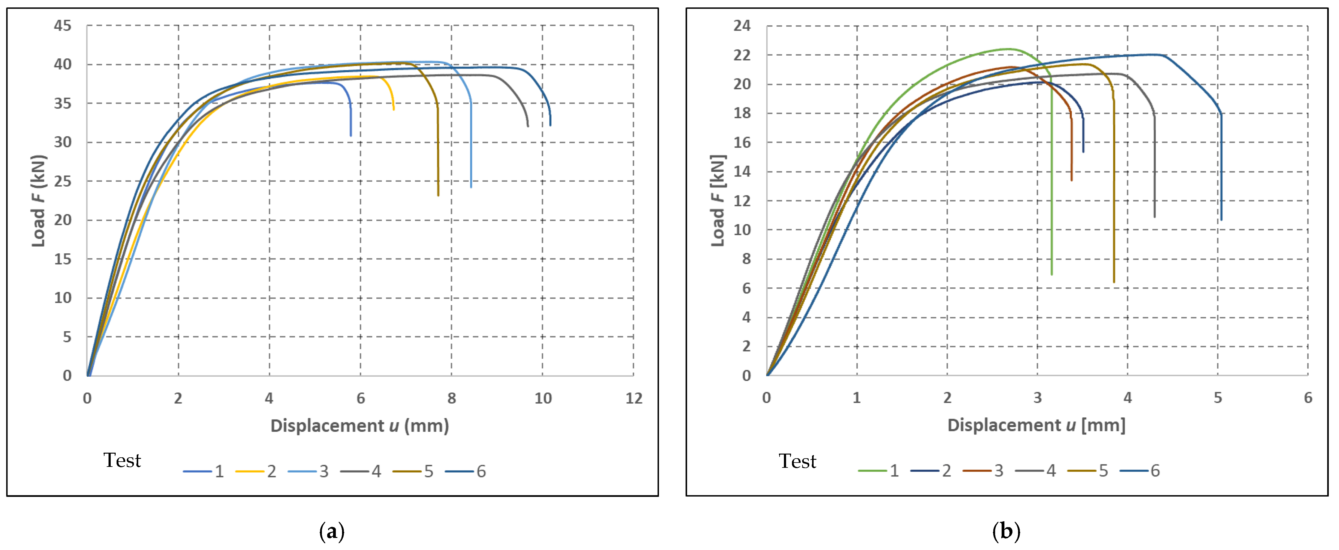
A total of six specimens were tested for each type of fastener. The load–deformation diagrams of the individual tests are shown in Figure 7.
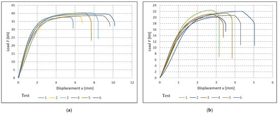
Figure 7.
Load–displacement diagrams of fasteners: (a) threaded rods; and (b) full-threaded bolts.
Tensile strength in the range of 912.88 MPa–977.96 MPa was achieved in the case of bolts. The course of the loading was very similar for all specimens. The area of linear loading and the subsequent formation of plastic deformations are well observable from the load–deformation curves. Tensile strength in the range of 1056.26 MPa–1142.25 MPa was achieved in the case of full-threaded screws. The course of the loading was very similar to the previous test.
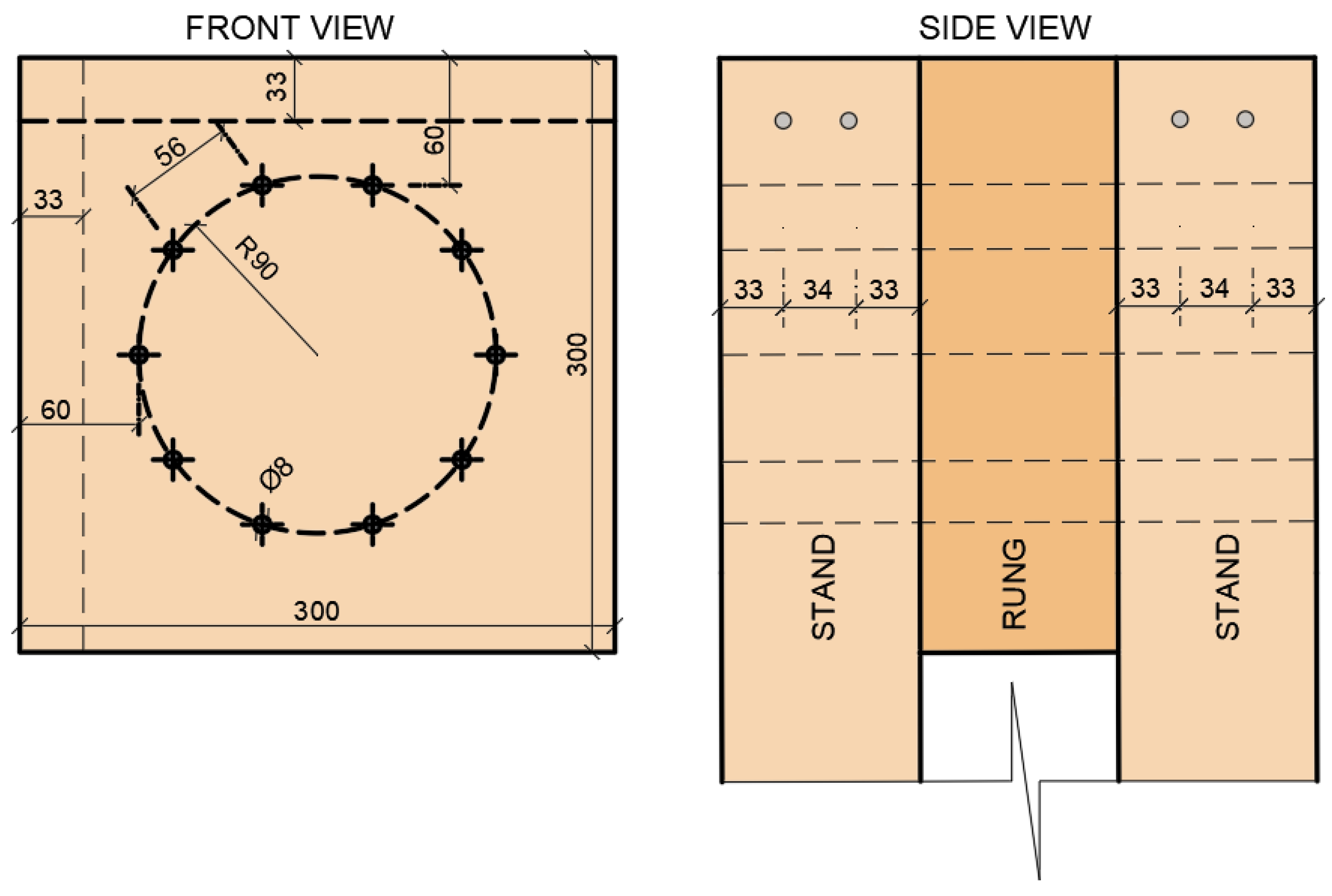
The timber structure system of the experiment was created from a semirigid connection of two frame struts and a crossbar. In total, two identical construction systems were created, the only difference being the fastener used. Experiment A contained a combination of bolts and dowels as fasteners, and the second experiment (B) involved full-threaded screws. The strut segment had a cross-section of 100/300 mm, and the cross-member segment had a cross-section of 100/300 mm. The arrangement of fasteners in both experiments was identical. They were located on one symmetrical circle with a radius r = 90 mm with a number of 10 pieces. The arrangement of the connecting means is shown in Figure 8. The selected geometry met the basic conditions of the distance from the edges and between the connecting means given by Koželouh (2004) [35]. The figure below also shows the reinforcement of the individual segments. The reinforcement was made using two full-threaded screws inserted next to each other on one segment of the structure with a diameter of 8 mm and a length of 300 mm. The deployment was performed on the basis of analytical assumptions of the action of the highest tensile stresses perpendicular to the fibers.
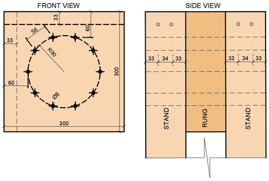
Figure 8.
Deployment of fasteners.
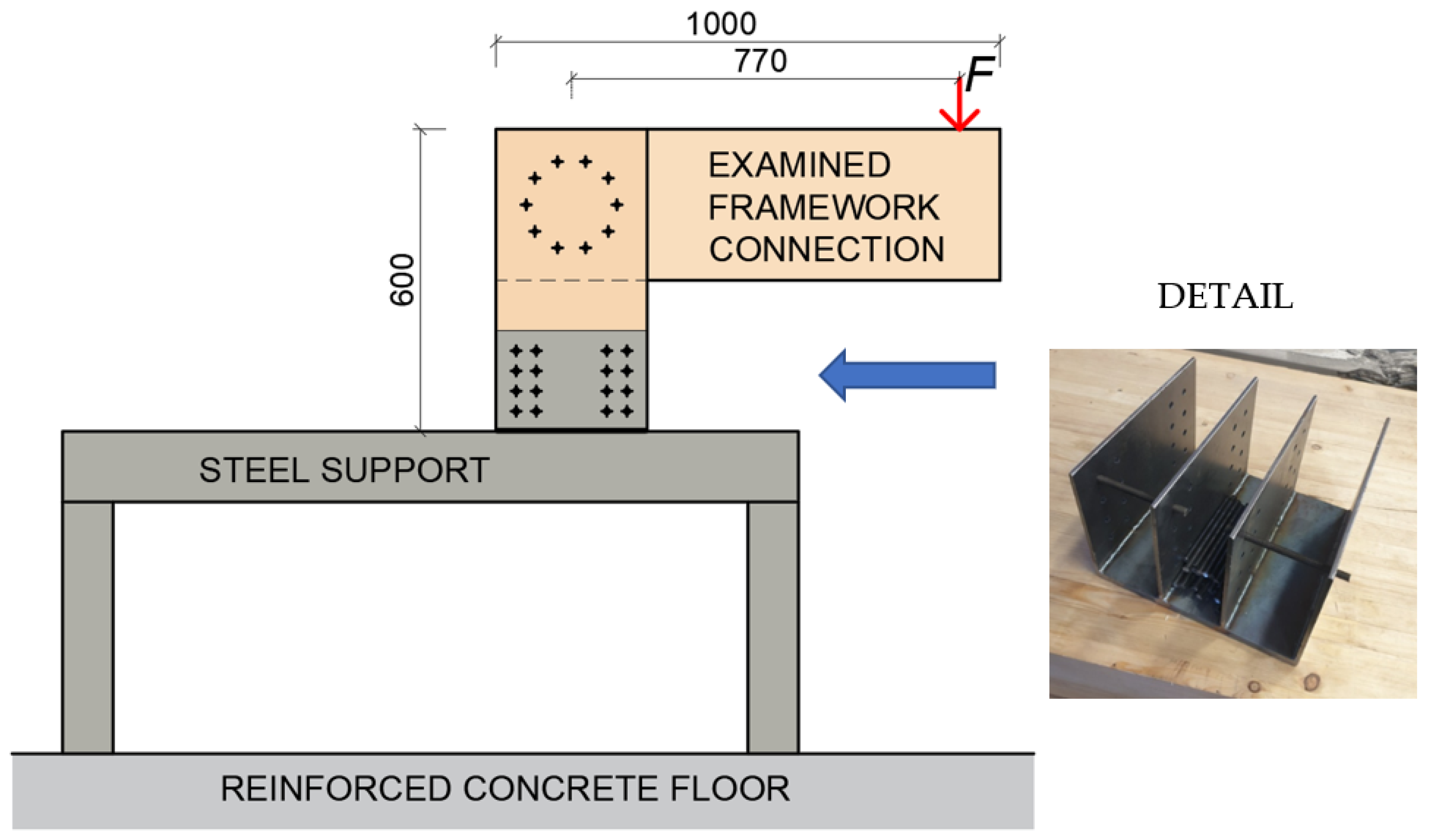
In order to perform these experiments, it was necessary to create the boundary conditions of the structure. To ensure the correct boundary conditions, a steel structure was designed, calculated, and made into a steel plate of the desired shape, which was fastened by means of bolts and into which semirigid connection struts were subsequently fastened by means of 24 bolts with a diameter of 8 mm. This connection was precalculated and designed to be four times the estimated force that would cause the connection to collapse. The entire steel structure was placed on a reinforced concrete floor and centered at the required distance from the press head so that the press would push exactly to the desired location on the front. A schematic representation of the experiment is shown in Figure 9.
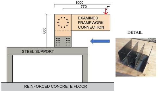
Figure 9.
Schematic of the experiment and support detail.
2.2. Description of Test Equipment
Experimental testing was performed on a LabTest 6.1200 electromechanical tester from Labortech, Opava Czech Republic [36]. This test equipment allows tensile, compressive static, and cyclic dynamic testing. On the test equipment, it is possible to perform the tests using a deformation load, with a speed ranging from 0.0005 mm/min to 250 mm/min, or using a force load up to 1200 kN with a measurement accuracy of 1%. The control of the test equipment is ensured by a PC with software Scia Engineer 20, Czech Republic [37].
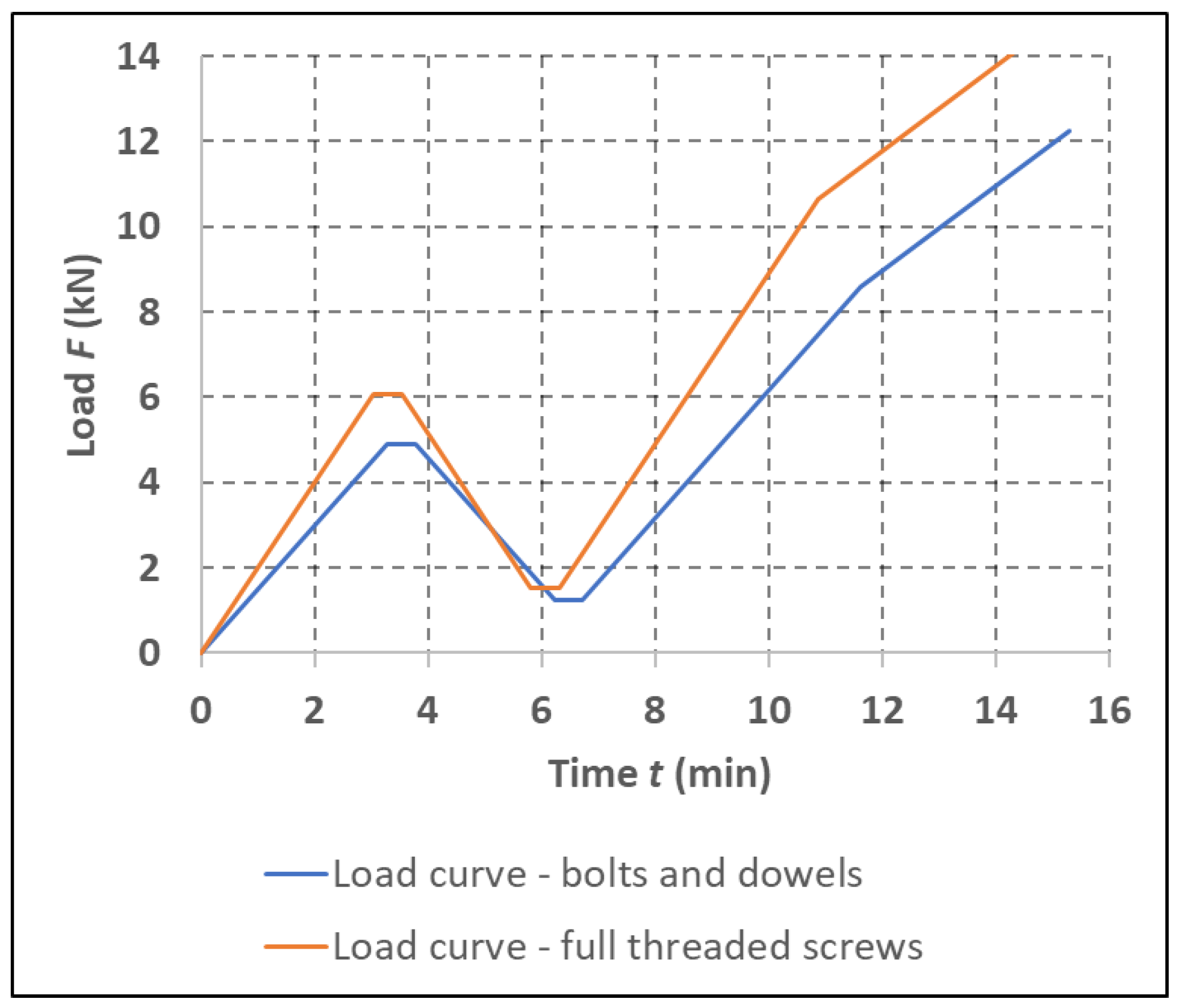
2.3. Description of the Static Test Load
The loading of the test specimens was static according to Figure 10 until the specimens failed. During testing, there was continuous a recording of time, force, deformation, and displacement of the press head. The loading process was performed in accordance with standard EN 26891 [38], which specifies the loading procedure for the experimental testing of connections of timber structures. This standard specifies the following loading procedure:
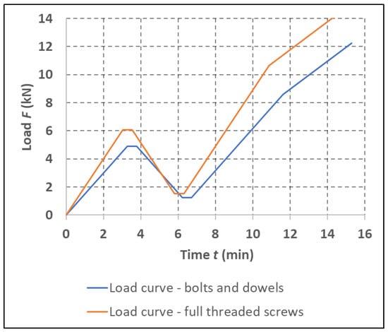
Figure 10.
Load curves of the individual experiments.
- Estimation of the maximum load Ftest for the tested connection type based on experience, calculation, or preliminary tests;
- Loading of the test specimen at a level of 40% of the Ftest value, held for 30 s;
- Loading of the test specimen to a level of 10% of the Ftest value, held for 30 s;
- Continuous loading until specimen failure.
Table 4 shows the values determining the course of each experimental load. The Ftest value was calculated as the characteristic load capacity (without the use of partial material reliability factors γm and the γcon connection). The characteristic load capacity of one fastener was calculated according to Eurocode 5 [11]. The individual steps, the size of the load, and the load speed were determined according to the EN 26891 standard [38].
Table 4.
The test course of the experiment setup.
2.4. Experimental Testing
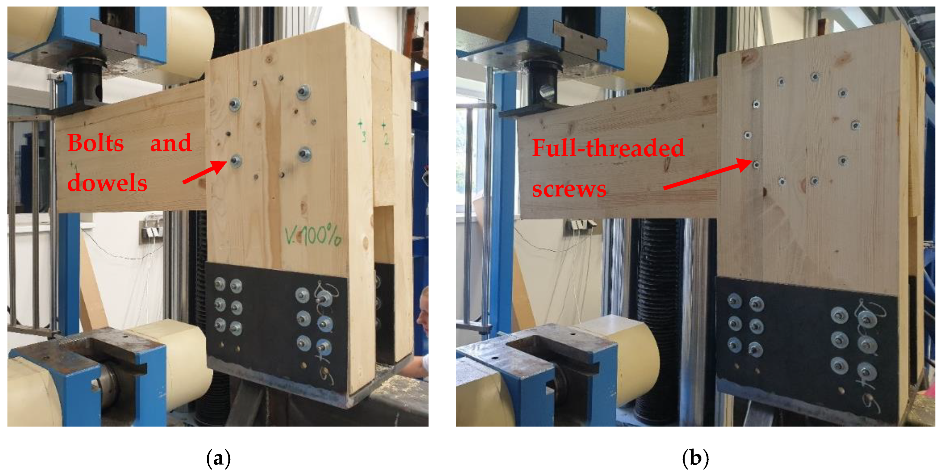
Individual experiments were tested at the Center of Building Experiments and Diagnostics, Faculty of Civil Engineering VSB, Technical University of Ostrava, Czech Republic. Figure 11 shows experiment A (a) using a combination of bolts and dowels and experiment B (b) using a full-threaded bolt before static loading. This image shows the unreinforced experimental specimens. The reinforced experimental segments are shown in Figure 12. In Figure 9, an arrow with force F is schematically shown. In fact, the load was applied by means of a steel cylinder with a diameter of 100 mm, and a rubber washer with a thickness of 10 mm was inserted under this steel cylinder to limit the local damage to the wood by the load. The load area of the steel plate corresponds to a typical design. The load area, e.g., corresponds to the load column.

Figure 11.
Experimental specimen: (a) experiment A using bolts and dowels; and (b) experiment B using full-threaded screws.
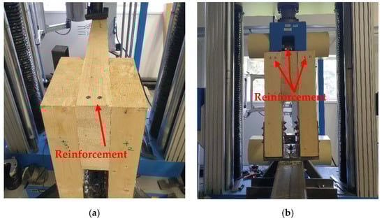
Figure 12.
Illustration of the reinforcement of segments of individual experiments: (a) reinforcement of the rung; and (b) reinforcement of the rung and struts (stands).
3. Results
3.1. Results of Experiments
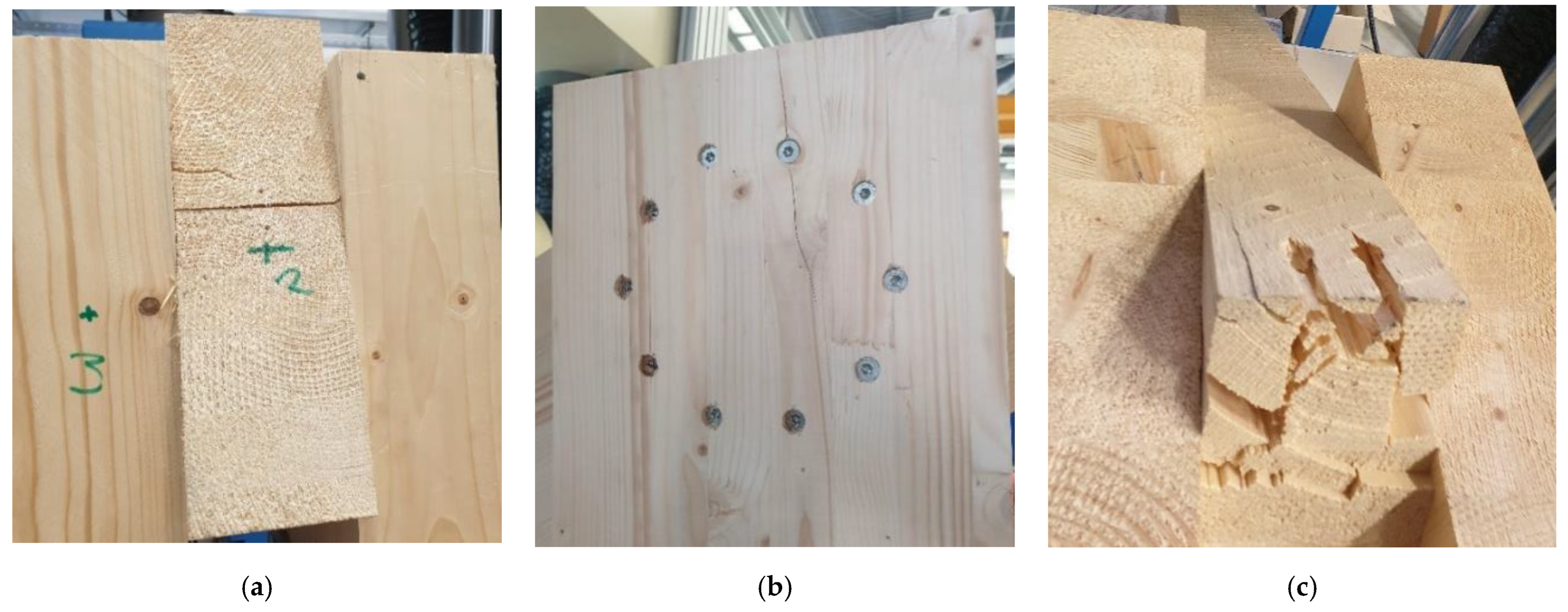
Figure 13 shows the broken individual reinforced and nonreinforced experiment A specimens, using bolts and dowels, after the static loading test. Figure 14 shows the failure of the individual reinforced and nonreinforced specimens of experiment B, using full-threaded bolts.

Figure 13.
Experiment A: (a) failure without reinforced segments; (b) reinforcement with reinforced rung; and (c) breach with reinforced rung and struts (stands).
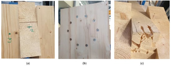
Figure 14.
Experiment B: (a) failure without reinforced segments; (b) reinforcement with reinforced rung; and (c) breach with reinforced crossbeam and struts (stands).
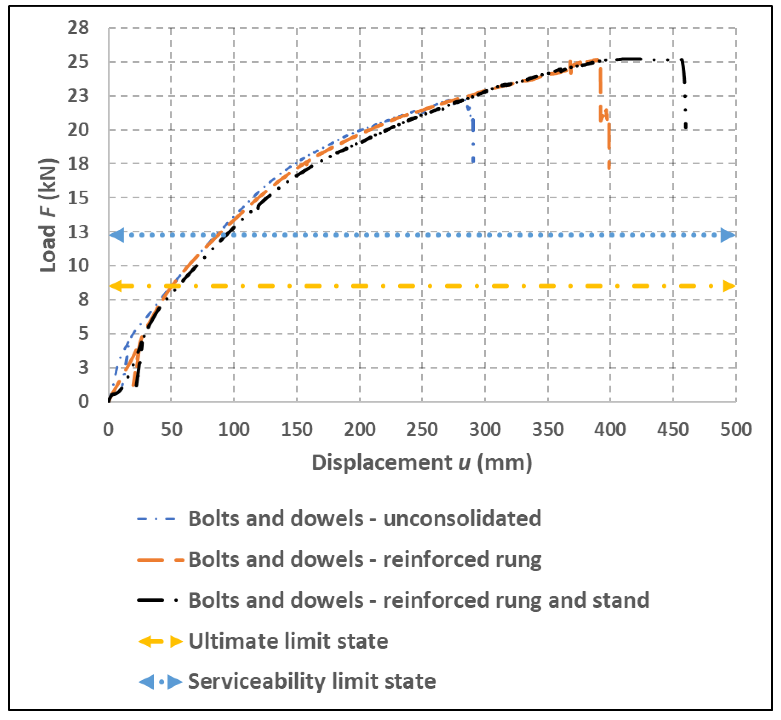
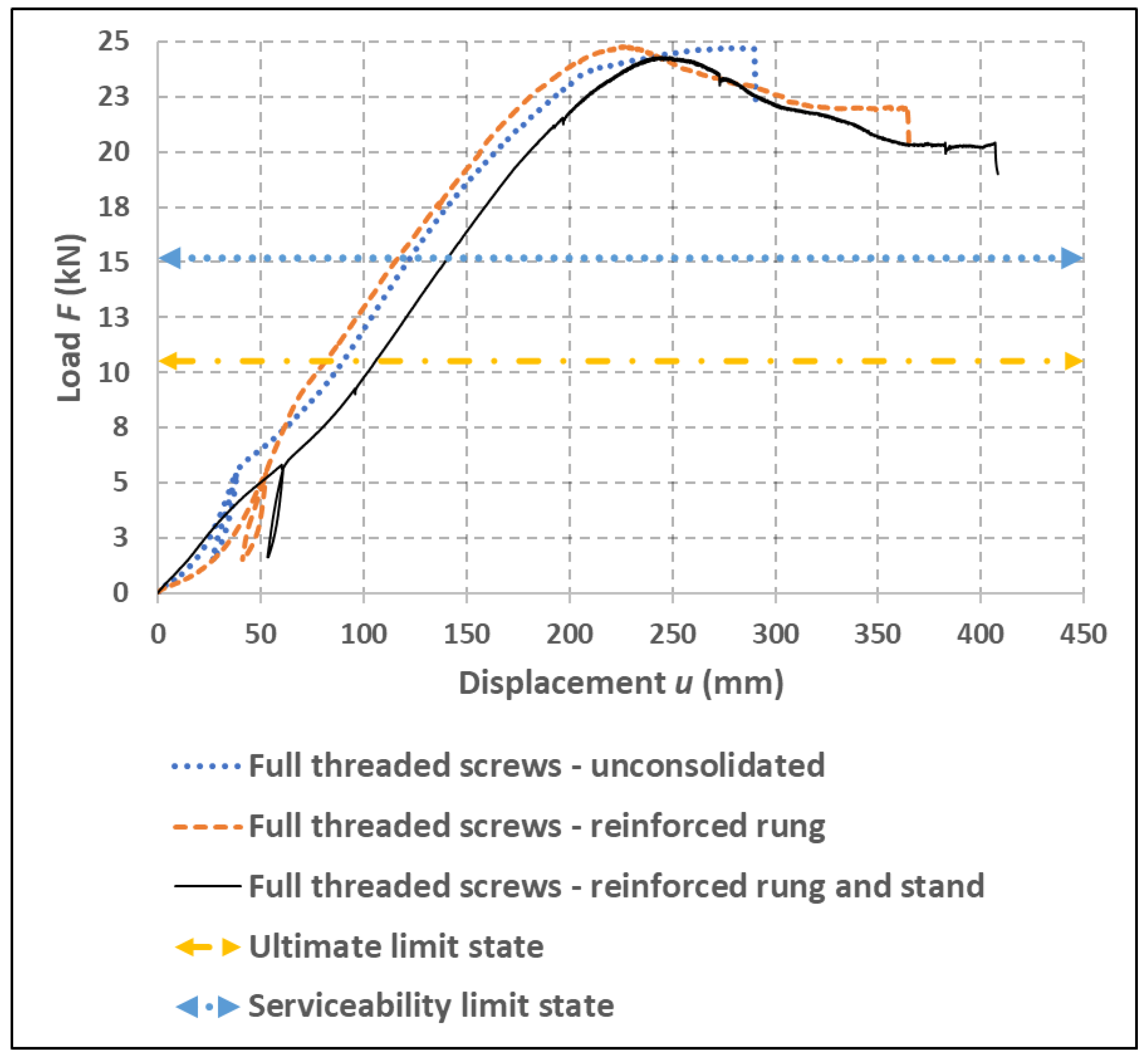
Figure 15 shows the load–deformation curves of experiment A, using bolts and dowels, with a variation of the reinforced and nonreinforced segments of the semirigid connection. Figure 16 shows the load–deformation load curves of experiment B, using full-threaded bolts, with a variation of reinforced and nonreinforced segments. These figures also show the individual limit state levels, where ULS represents the calculated value for the ultimate limit state, and SLS represents the calculated value for the serviceability limit state according to Eurocode 5 [11].
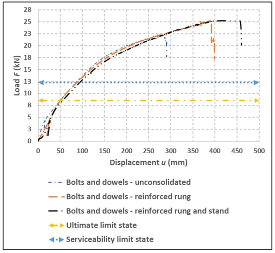
Figure 15.
Load–deformation curves of individual specimens of static cyclic stress of experiment A, using bolts and dowels.
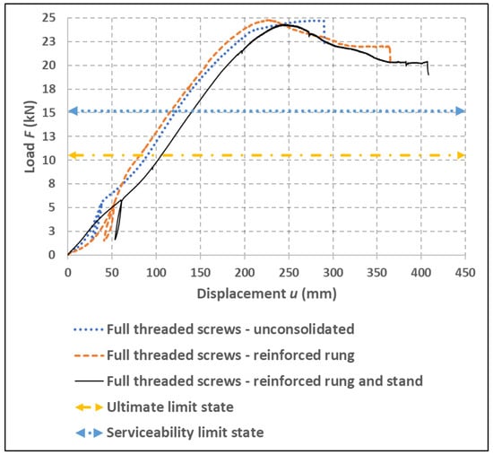
Figure 16.
Load–deformation curves of individual specimens of static cyclic loading of experiment B, using full-threaded screws.
The ultimate limit state (ULS) was calculated using partial reliability factors, i.e., γcon for joints and kmod, γM for wood. The serviceability limit state (SLS) was calculated in the same way without considering partial reliability factors; therefore, the resulting load capacity was higher.
The results of individual tests are recorded in the tables below. Table 5 presents the results of the semirigid connection of experiment A, using bolts and dowels. Table 6 presents the results of experiment B, using full-threaded screws. The first column (Test) in the tables indicates the individual test, with test 1 corresponding to the nonreinforced segments, test 2 corresponding to the reinforced cross-member (rung), and test 3 corresponding to the reinforced cross-member and struts. The second column (Fmax,test) describes the maximum value reached under load. The third column (Fmax,d) shows the load capacity value at the load limit state according to Eurocode 5 [11], and the fourth column (Fmax,k) shows the load capacity value at the serviceability limit state according to the Eurocode 5 [11]. The fifth column (d) is the ratio between the ultimate limit value and the value achieved by testing, and the sixth column (k) shows the ratio between the serviceability limit state and the value achieved by testing. The seventh column (u) shows the maximum vertical deformation of the free end of the cross-member, and the last column (ε) shows the ratio between the deformation of individual variations of reinforcement where the value of the unconsolidated specimen is taken as the basic value.
Table 5.
Results of experiment A, using bolts and dowels.
Table 6.
Results of experiment B, using full-threaded screws.
3.2. Ductility Calculation of Frame Connection
Thanks to the knowledge given in the standard, it was possible to determine the ductility of individual connections. The biggest problem when calculating ductility is calculating the yield strength of the connection. In this case, the procedure according to EN 12 512 [13] was used to calculate the yield strength
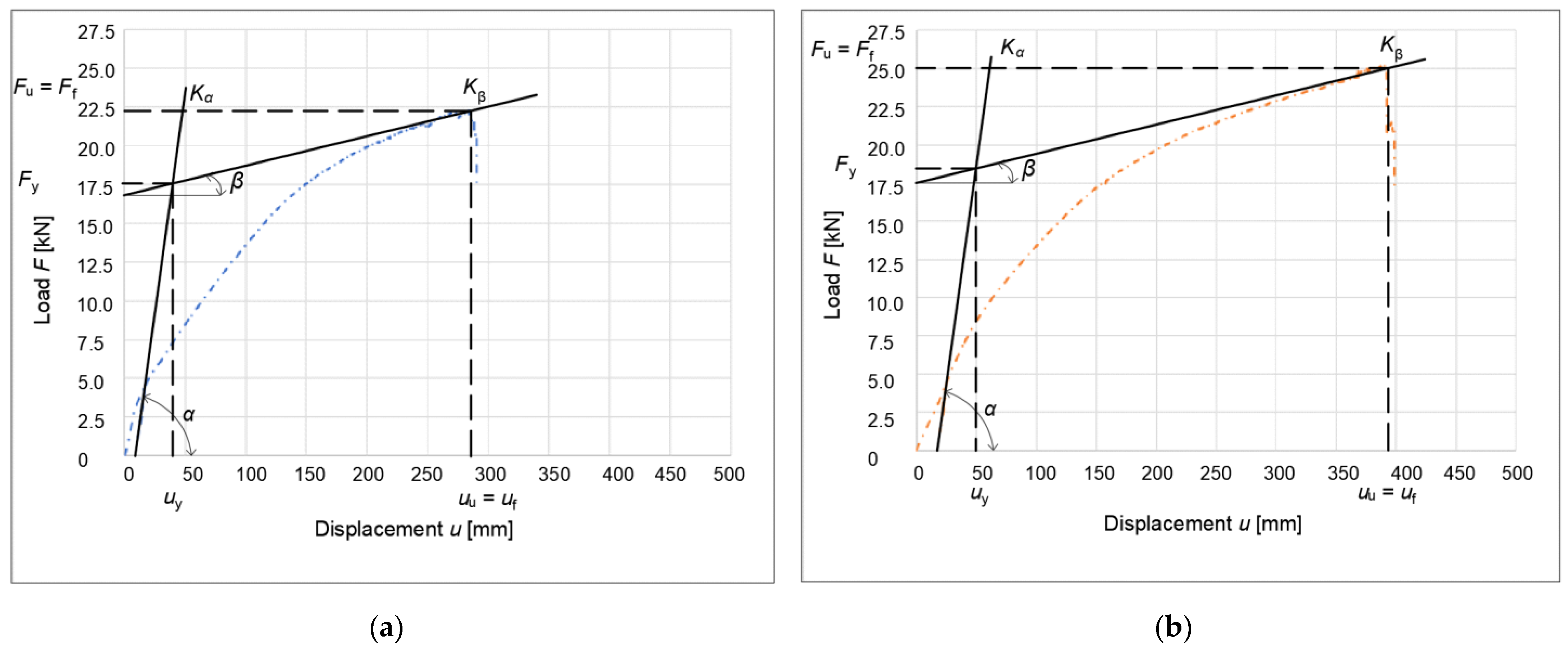
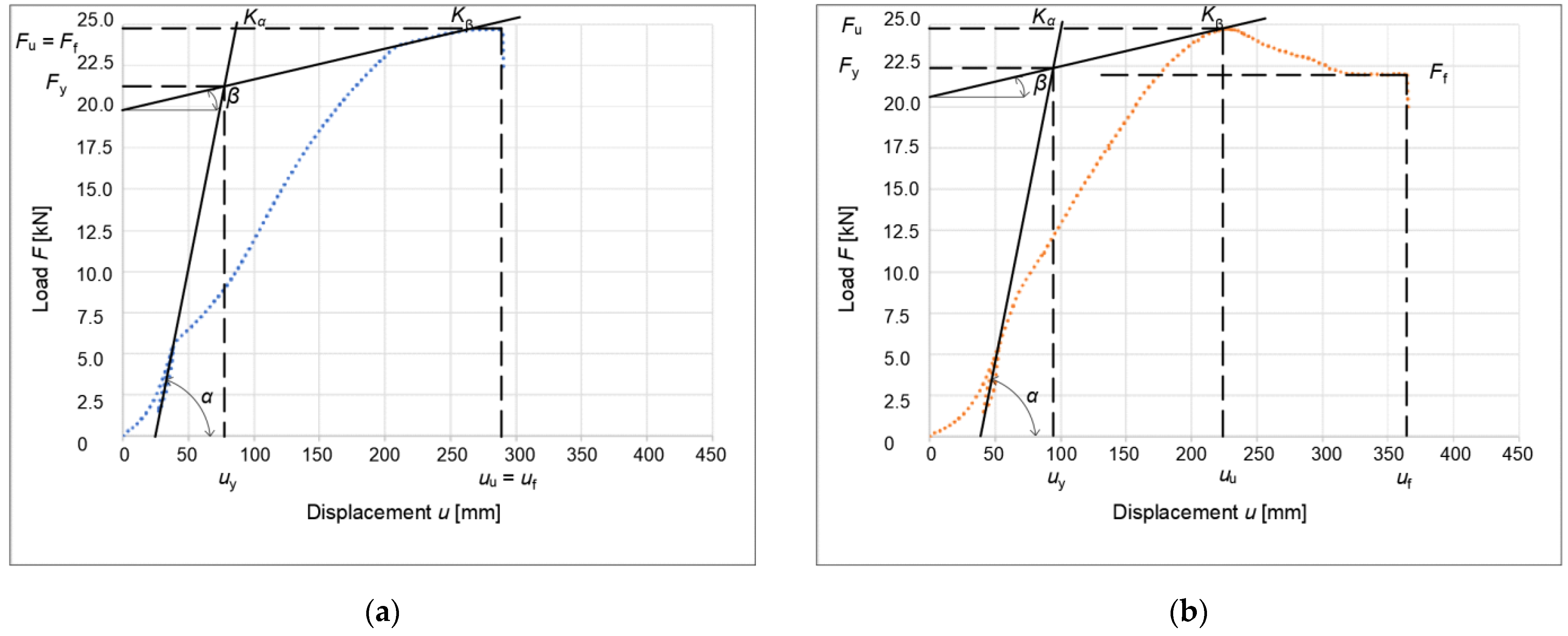
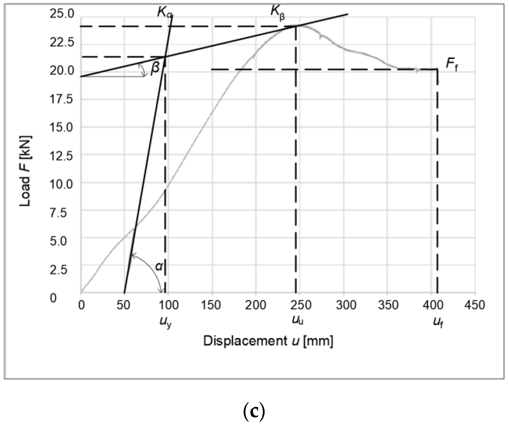
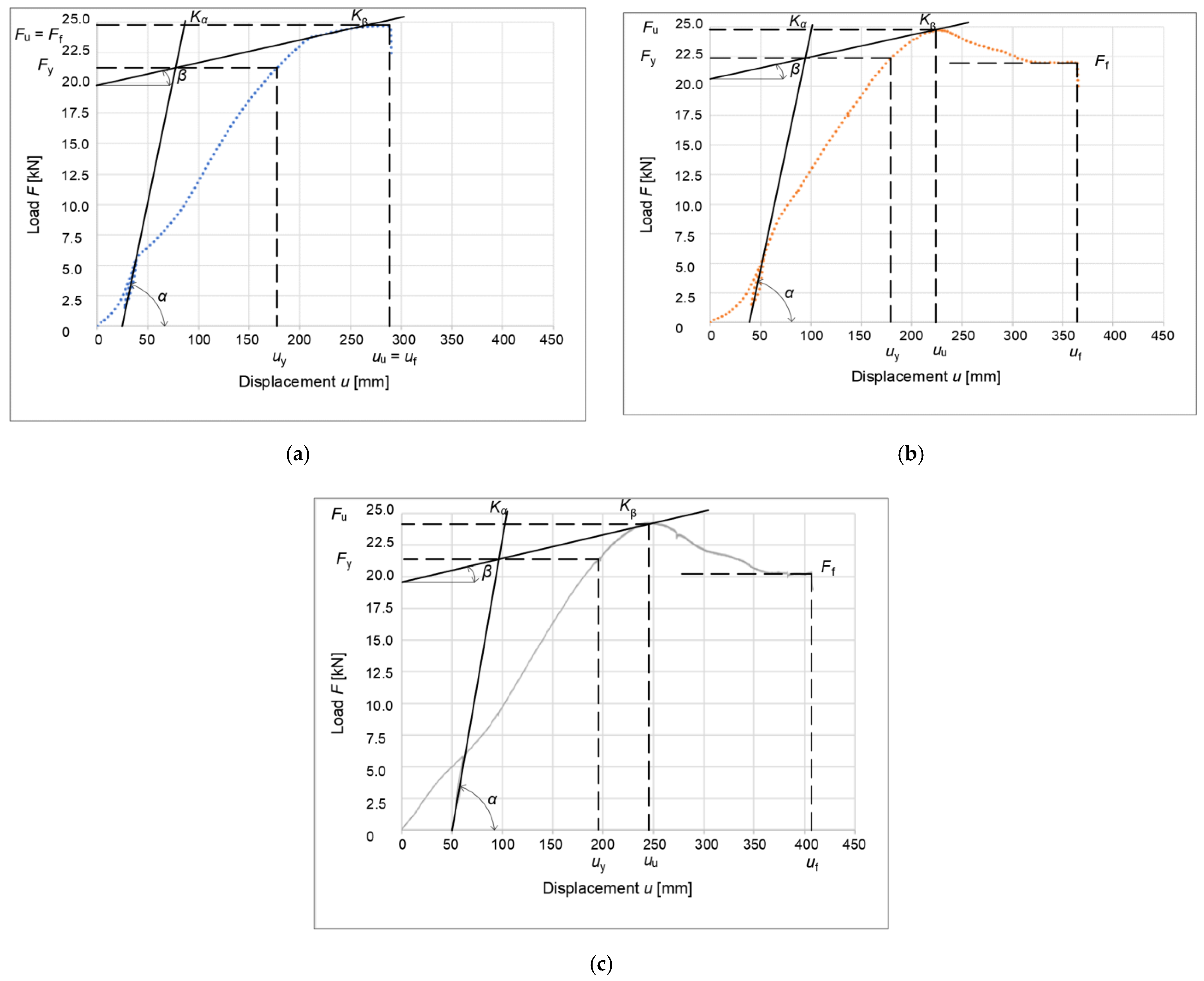
The procedure consists of obtaining deformation at the yield strength of the connection. This is then divided by the deformation at the failure limit, thus enabling one to obtain the ductility value of the connection and then classify the connection. Figure 17 shows a graphical method of obtaining the yield strength of a connection formed from bolts and dowels. Figure 18 shows a method of obtaining the yield strength of a connection formed from full-threaded bolts. The ductility of the connection was determined according to Table 7.
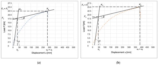
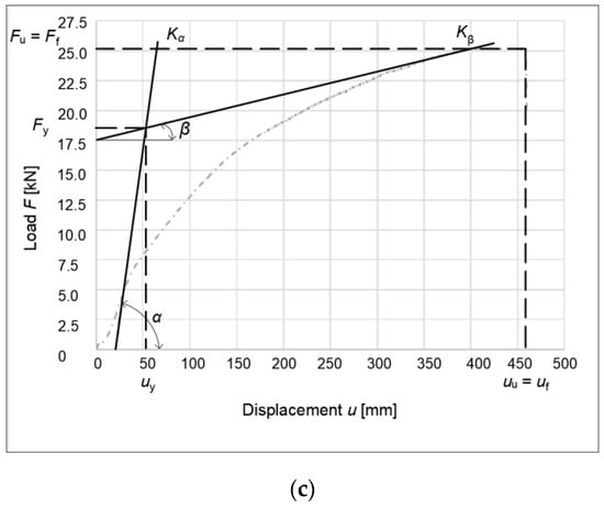
Figure 17.
Graphical representation of the yield strength of a connection formed from bolts and dowels according to EN 12512: (a) unreinforced specimen; (b) reinforced partitions; (c) reinforced rung and struts (stands). Kα, stiffness of the connection at the yield point; Kβ, stiffness of the connection at the ultimate point; α, slope of the curve at the yield point; β, slope of the curve at the ultimate point; uy, deformation at the yield point; uu, deformation at the ultimate point; uf, deformation at the failure point; Fy, force at the yield point; Fu, force at the ultimate point; and Ff, force at the failure point.
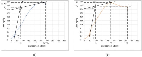

Figure 18.
Graphical representation of the yield strength of a connection formed with screws according to EN 12512: (a) unreinforced specimen; (b) reinforced partitions; and (c) reinforced rung and struts (stands).
Table 7.
Ductility classification according to standard and research article.
The results of the calculated values of ductility and classification are contained in Table 8.
Table 8.
Comparison of ductility results of experiments.
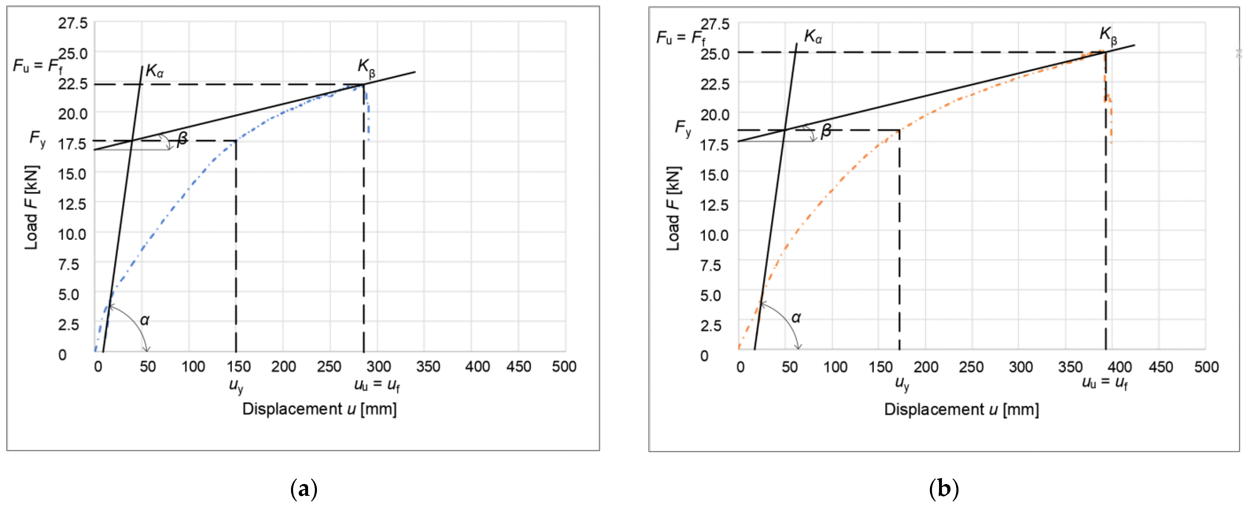
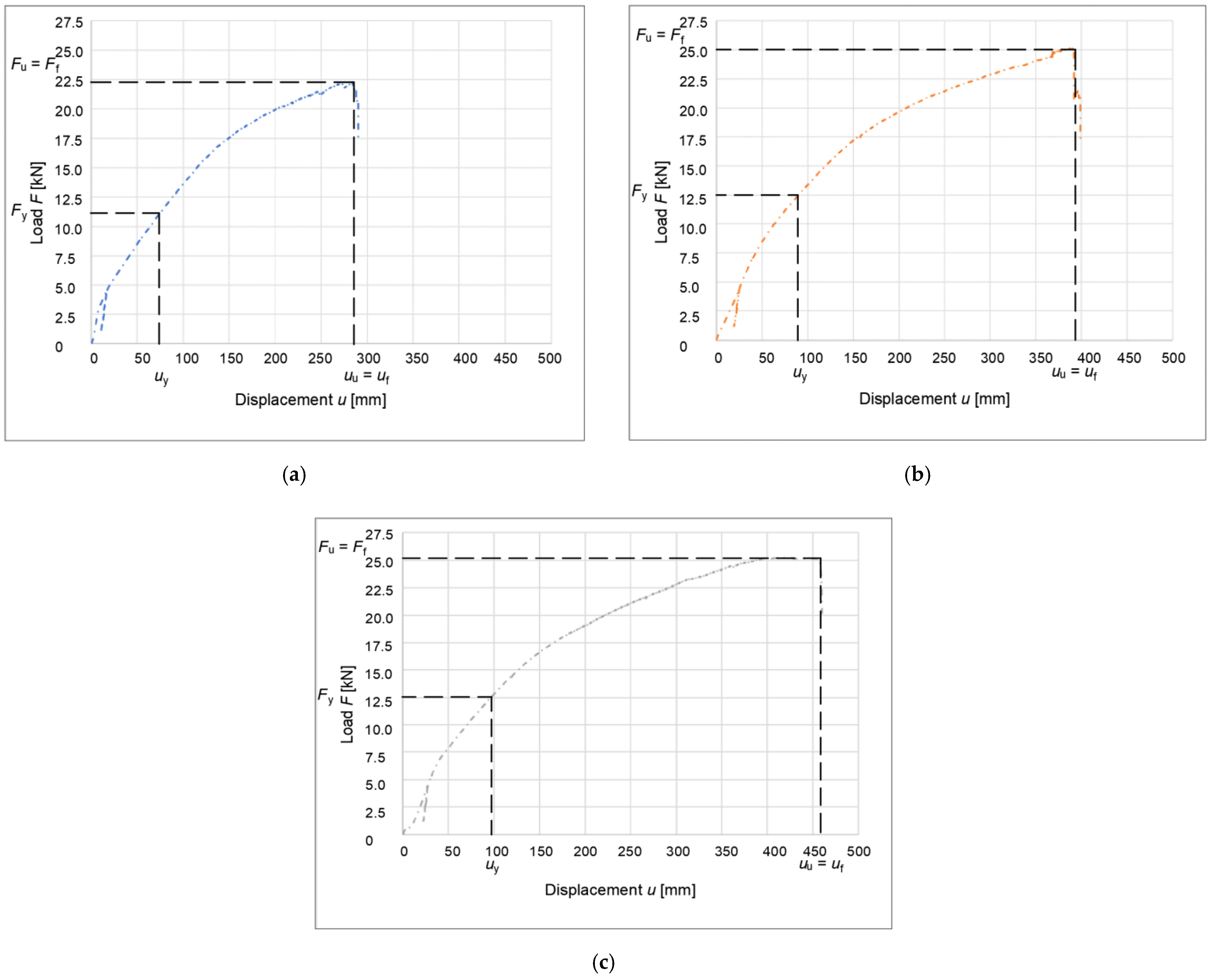
Another method used to obtain ductility is that described by Yasamura and Kawai (1998) [14]. This method is very similar to the method described in EN 12512 [13]. The difference, however, is in obtaining the yield point; in this method, the deformation at the yield point is subtracted by intersecting a horizontal line with the working diagram of the connection. In the standard method, this value is read by crossing a vertical line with a working diagram. Figure 19 and Figure 20 show a graphical method for obtaining ductility according to Yasamura and Kawai (1998) [14].
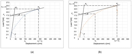

Figure 19.
Graphical representation of the yield strength of a connection formed from bolts and dowels according to Yasamura and Kawai (1998): (a) unreinforced specimen; (b) reinforced partitions; and (c) reinforced rung and struts (stands).
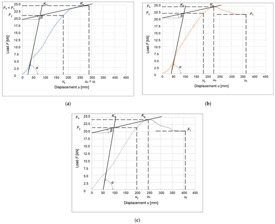
Figure 20.
Graphical representation of the yield strength of a connection formed with screws according Yasamura and Kawai (1998): (a) unreinforced specimen; (b) reinforced partitions; and (c) reinforced rung and struts (stands).
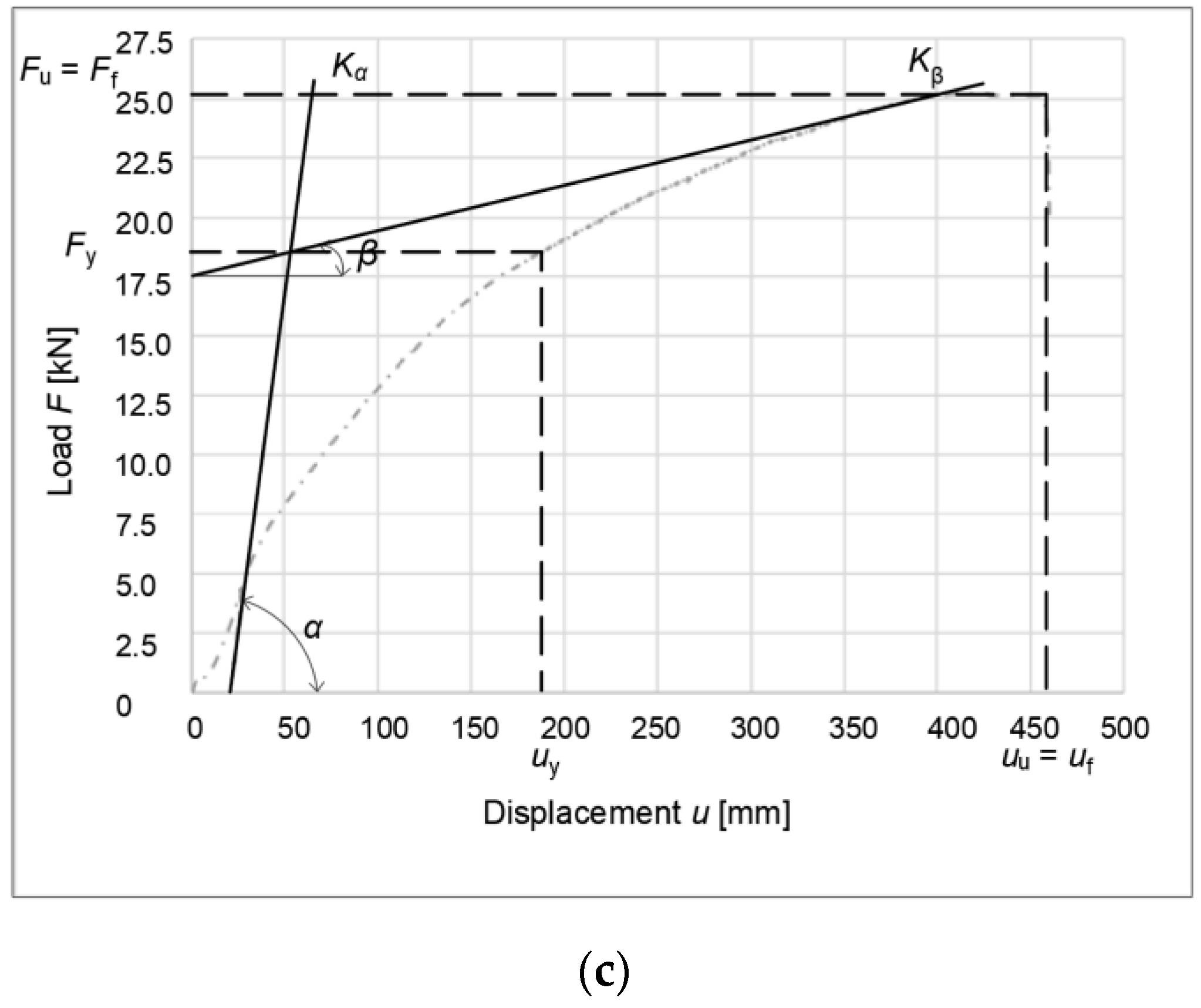
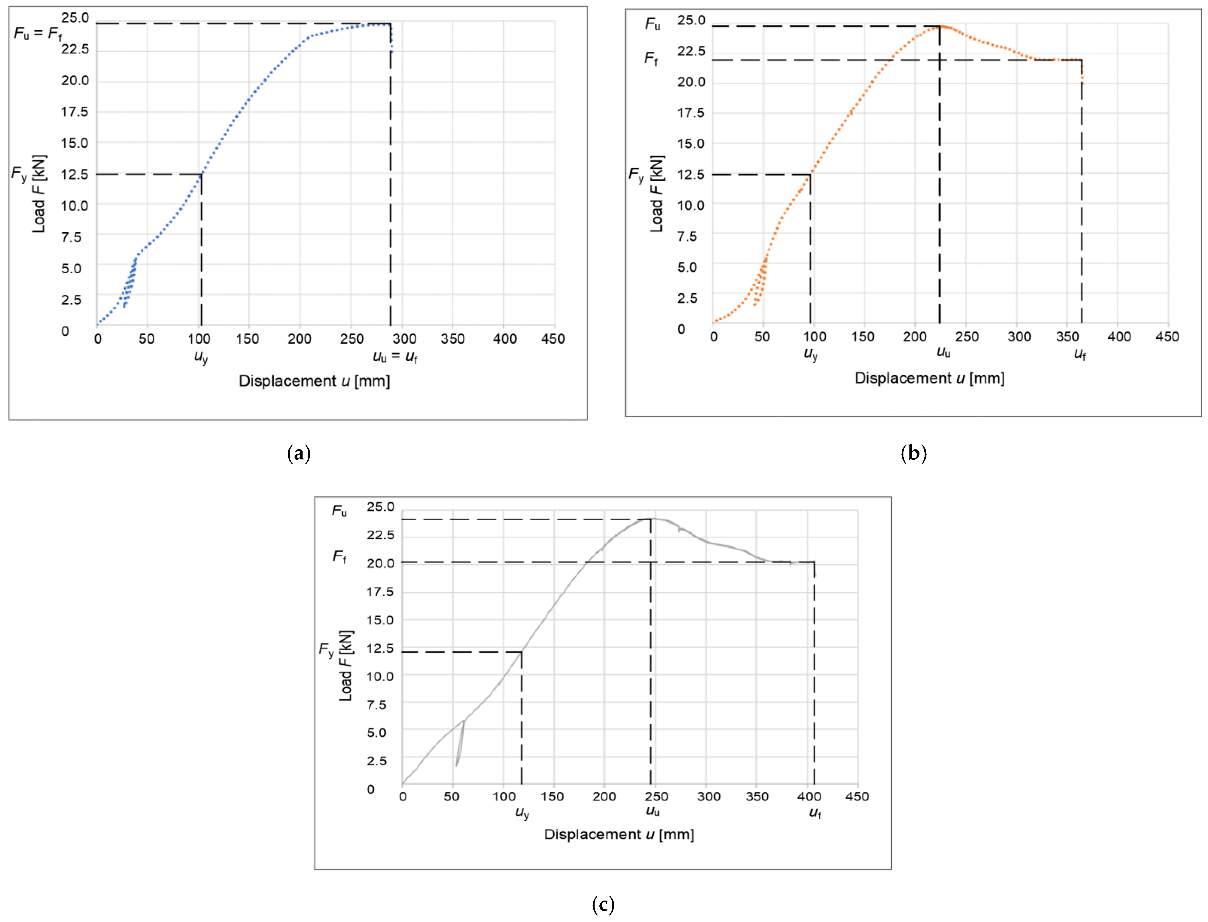
Another method for comparing results is that described by Karacabeily and Ceccotti (1998) [15]. Obtaining the yield strength in this process is very easy. The yield point deformation is located at 50% of the load capacity. The carrying capacity is the mean value of the actual failure of a connection. Figure 21 and Figure 22 show a graphical method for obtaining ductility according to Karacabeily and Ceccotti (1998) [15].
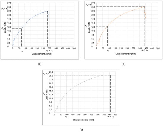
Figure 21.
Graphical representation of the yield strength of a connection formed from bolts and dowels according to Karacabeily and Ceccotti (1998): (a) unreinforced specimen; (b) reinforced partitions; and (c) reinforced rung and struts (stands).
Figure 22.
Graphical representation of the yield strength of a connection formed with screws according Karacabeily and Ceccotti (1998): (a) unreinforced specimen; (b) reinforced partitions; and (c) reinforced rung and struts (stands).
4. Discussion
When testing the experiments of structures in the early phase of loading, the individual connecting means were activated (seated). This initial consolidation was detected on the load–deformation diagram by its concave curvature and gradual increase in stiffness, i.e., strengthening. Gradual loading caused the timber mass to be embedded around the connecting means due to them pushing into the timber. This phenomenon can be seen in Figure 13 and Figure 14.
When testing the specimens without reinforced segments, a crack occurred during loading, which appeared in both specimens in the cross-section. Its formation was due to the tensile stress acting perpendicular to the fibers; in this direction, the timber had its lowest load-bearing capacity. The formation of this crack had a relatively loud accompaniment during loading for both specimens, which gradually lost their bearing capacity and thus collapsed.
The testing of the specimens with a reinforced cross-member resulted in the failure of the strut by tensile stress perpendicular to the fibers, thus breaking the connection. Crack formation was initiated abruptly without previous sound signals during loading. From the point of view of load-bearing capacity, the gradually consolidated specimen with bolt and dowel fasteners (experiment A) achieved a 10% increase in load-bearing capacity. However, the maximum load level was equal to the connection created using full-threaded bolts (experiment B). The course of the load–deformation curve had an increasing trend in the specimen with bolts and dowels, followed by the sudden failure of the strut. In contrast, upon strengthening the cross-section in the screw connection, the load–deformation curve first showed an increasing trend with a clearly visible peak load, followed by a significant decrease in stiffness due to the crack, as well as a reduction in load-bearing capacity and subsequent collapse.
When testing specimens with reinforced rounds and struts (stands), the rounds were broken, especially in the area of reinforcement. During the testing of the bolt and dowel specimen, the load-bearing capacity also increased compared to the unreinforced specimen to the level seen with the screw fastener. The load–deformation curve had an increasing trend with a peak at which a crack appeared in the cross-member, followed by the subsequent collapse of the connection. In contrast, there was no increase in the load-bearing capacity of the unreinforced specimen in the connection with the bolts; with the formation of a crack in the cross-section, there was a decrease in stiffness and load-bearing capacity, but the connection was able to withstand the load.
The achieved results of the calculation for individual types of connections, including the final ductility values, are shown in Table 8. In this table, uy denotes the calculated yield stress, uf denotes the failure limit deformation, and Di denotes the calculated ductility value for the connection; the connection is classified in the last column, according to standard EN 12512 [13] for individual calculation methods. According to this standard, a classification of 1 indicates a brittle connection, whereas a classification of 4 indicates a connection with high ductility.
From the above results, it is possible to observe an interesting comparison of individual access methods. In the method determined according to EN 12 512 [13], the connection made using bolts and dowels was classified during all degrees of reinforcement into the highest possible ductility class 4, compared to the connection made using screws. This was reduced to class 3 by gradual consolidation. Even when looking at the load–deformation curve of the bolt, brittle failure of the connection was indicated, whereas after the calculation, the opposite was true. The relatively low value of deformation at the yield point led this connection to a high value of ductility. In contrast, the screw connection induced the ideal course of a very ductile connection with its maximum load-bearing capacity and a consequent decrease in stiffness and load-bearing capacity. However, the deformation ratio at the yield point was less favorable in this case than the previous type of connection; therefore, its classification from a ductility point of view was lower.
According to the method of Yasamura and Kawai (1998) [14], the method of obtaining the yield strength of the connection is a bit stricter, thus classifying all types of connection at a very low level in terms of ductility. Specifically, the connection created with the bolts and dowels was degraded from class 4 to class 1 for the unreinforced specimen and class 2 by consolidation. This reduction in the ductility class also applied to the connections formed with the screws. Specifically, it was degraded from class 2 for the unreinforced specimen to class 1, indicating a brittle connection. With gradual consolidation, it returned to class 2, indicating a connection with low ductility. This ductility classification is significantly different from the standard classification and classifies a very high ductility connection as a brittle connection, which is counterproductive.
The method described in the work of Karacabeyli and Ceccotti (1998) [15] is one of the simplest methods for determining the yield strength of a connection in terms of difficulty. However, this method also degrades both types of connections to a lesser level, but not as drastically as the method of Yasamura and Kawai (1998) [14]. Specifically, a degraded connection was formed using bolts and dowels, achieving class 2 for the unreinforced specimen. By gradually strengthening this connection, the level of ductility was increased by one degree to class 3, indicating a connection with medium ductility. The unreinforced connection created from the screws remained at class 2 even after classification by this method. However, this connection was no longer able to reach a higher level of ductility even upon gradually strengthening the segments.
According to the data obtained, the test with reinforced segments, i.e., C, was classified as described below. The connection created with bolts and dowels achieved classification classes of class 4, 2, and 3. Accordingly, it is theoretically possible to classify the connection as class 3, indicating a connection with moderate ductility. The connection created with screws ranged from class 3 to 2 according to individual methods. Accordingly, it is also possible to draw a theoretical conclusion that the joint can be classified as class 2, indicating a low-ductility connection. It should be noted that the only valid method is classification according to EN 12 512 [13]; the other methods were selected as alternative methods for comparison. The testing of experiment A, using bolts and dowels, confirmed the safety and reliability of these standard fasteners in forming a semirigid connection. Testing showed that the most effective approach is to strengthen both segments of the semirigid connection, i.e., struts (stands) and rounds. By such reinforcement, increased deformation of the connection was achieved before collapse, leading to a more reliable and safer design of such a structure.
5. Conclusions
This article focused on the issue of semirigid connections of timber beams and struts connected by mechanical means of the dowel type. Specifically, three specimens were tested by static load testing with bolt and dowel combination fasteners, while three specimens were tested with full-threaded bolts. This study required the creation of analytical assumptions, which were the basis for the design of experimental tests, followed by a comparison of the results.
The experimental testing of the connection formed from a standard combination of bolts and dowels (experiment A; Figure 15), without reinforced segments, proved its reliability and safety. The connection collapsed at 2.62 times the design load value determined according to Eurocode 5 [11]. Although the primary goal of reinforcing the façade is to achieve greater deformation, i.e., ductility, before collapse, there was a slight 10% increase in load-bearing capacity over the unreinforced specimen. With this increased increase in load-bearing capacity, the threaded rod in experiment A was compared to the full-threaded bolt in experiment B. Upon strengthening the individual segments, there was no increase in the ductility class. This connection was always classified according to EN 12512 [13] in the highest class (class 4), indicating a connection with high ductility. This was due to the specimen’s low deformation at the yield point and high deformation during collapse.
The experimental testing of the connection formed from full-threaded screws (experiment B; Figure 16) proved its safety and reliability for normal use in practice. This is because a semirigid connection made using full-threaded screws is not commonly used in practice. The connection broke at 2.35 times the design load value determined according to Eurocode 5 [11]. The strengthening of the round did not increase the load-bearing capacity of the connection, but there was a 1.26-fold increase in vertical deformation, and the strengthening of the round and the struts resulted in a 1.41-fold increase in deformation compared to the unreinforced specimen. From the point of view of the ductility classification according to the EN 12512 standard [13], upon strengthening the round and the struts, the ductility class was increased to class 3, indicating a connection with moderate ductility.
Although the connection made using full-threaded screws reached a lower ductility class according to the standard, its use can be considered very safe. By comparing the load–deformation diagrams of individual experiments (Figure 15 and Figure 16), we can see that, in the case of experiment B, using full-threaded bolts, a relatively linear course was established up to the level of the highest load capacity. After reaching the maximum load-bearing capacity, a decrease in stiffness can be seen, indicating a leveling of the curve, followed by a consequent reduction in load-bearing capacity and collapse. In the case of experiment A, using bolts and dowels, we can observe a linear course approximately to the value determined by the ultimate limit state. The curve of the load– deformation curve acquired a nonlinear course, i.e., plastic deformations, after exceeding this limit state. In this nonlinear course, a decrease in stiffness can also be observed, indicating a smaller slope of the curve. Upon reaching the maximum load capacity, this connection collapsed, decreasing the stiffness and load capacity, as in the case of using full-thread screws.
Experimental testing confirmed that, by strengthening the site of the expected collapse of the connection, it is possible to delay the time to collapse, as well as increase the deformation during collapse. The use of full-threaded screws for reinforcing connection segments is a very suitable solution from the point of view of assembly complexity, as well as financial complexity.
Research on the issue of determining the load-bearing capacity of connections of timber structures according to European standards (Eurocode 5) [11] is constantly evolving. The proposed experiments, which aimed to determine the ductility of a semirigid connection between a timber beam and a strut formed by means of mechanical dowel-type fasteners, can contribute to this trend. The experimental data can also be used for the design of semirigid connections in terms of load-bearing capacity and ductility.
Author Contributions
Conceptualization, A.L.; validation, D.M.; data curation, M.J., P.M. and P.D.; methodology, O.S.; formal analysis and writing—original draft, M.J. and O.S.; supervision, A.L. All authors have read and agreed to the published version of the manuscript.
Funding
This research was funded by VSB-TUO by the Ministry of Education, Youth and Sports of the Czech Republic. The supported project has the number 2022/55 of Student Research Grant Competition of the VSB-Technical University of Ostrava.
Institutional Review Board Statement
Not applicable.
Informed Consent Statement
Not applicable.
Data Availability Statement
Data are contained within the article.
Acknowledgments
Experimental measurements and research were carried out thanks to VSB Technical University of Ostrava. The work was supported by the Student Research Grant Competition of the VSB-Technical University of Ostrava under identification number 2022/55.
Conflicts of Interest
The authors declare no conflict of interest.
References
- Nowak, T.; Patalas, F.; Karolak, A. Estimating Mechanical Properties of Wood in Existing Structures—Selected Aspects. Materials 2021, 14, 1941. [Google Scholar] [CrossRef] [PubMed]
- Malo, K.A.; Abrahamsen, R.B.; Bjertnæs, M.A. Some structural design issues of the 14-storey timber framed building “Treet” in Norway. Eur. J. Wood Prod. 2016, 74, 407–424. [Google Scholar] [CrossRef] [Green Version]
- Crocetti, R. Large-span timber structures. In Proceedings of the World Congress on Civil, Structural and Environmental Engineering (CSEE’16), Prague, Czech Republic, 30–31 March 2016; pp. 1–23. [Google Scholar] [CrossRef]
- Frühwald, E. Analysis of structural failures in timber structures: Typical causes for failure and failure modes. Eng. Struct. 2011, 33, 2978–2982. [Google Scholar] [CrossRef]
- Steiger, R.; Serrano, E.; Stepinac, M.; Rajčić, V.; O’Neill, C.; McPolin, D.; Widmann, R. Strengthening of timber structures with glued-in rods. Constr. Build. Mater. 2015, 97, 90–105. [Google Scholar] [CrossRef] [Green Version]
- Vavrusova, K.; Mikolasek, D.; Lokaj, A.; Klajmonova, K.; Sucharda, O. Determination of carrying capacity of steel-timber joints with steel rods glued-in parallel to grain. Wood Res. 2016, 61, 733–740. [Google Scholar]
- Zhou, S.-R.; Li, Z.-Y.; Feng, S.-Y.; Zhu, H.; Kang, S.-B. Effects of bolted connections on behaviour of timber frames under combined vertical and lateral loads. Constr. Build. Mater. 2021, 293, 123542. [Google Scholar] [CrossRef]
- Bouchaïr, A.; Racher, P.; Bocquet, J.F. Analysis of dowelled timber to timber moment-resisting joints. Mater. Struct. 2007, 40, 1127–1141. [Google Scholar] [CrossRef]
- Johanides, M.; Kubíncová, L.; Mikolášek, D.; Lokaj, A.; Sucharda, O.; Mynarčík, P. Analysis of Rotational Stiffness of the Timber Frame Connection. Sustainability 2021, 13, 156. [Google Scholar] [CrossRef]
- Lokaj, A.; Dobes, P.; Sucharda, O. Effects of Loaded End Distance and Moisture Content on the Behavior of Bolted Connections in Squared and Round Timber Subjected to Tension Parallel to the Grain. Materials 2020, 13, 5525. [Google Scholar] [CrossRef]
- ČSN EN 1995-1-1; Eurocode 5: Design of Timber Structures—Part 1-1: General—Common Rules and Rules for Buildings. Czech Standards Institute: Praha, Czech Republic, 2006.
- Dobes, P.; Lokaj, A.; Mikolasek, D. Load-Carrying Capacity of Double-Shear Bolted Connections with Slotted-In Steel Plates in Squared and Round Timber Based on the Experimental Testing, European Yield Model, and Linear Elastic Fracture Mechanics. Materials 2022, 15, 2720. [Google Scholar] [CrossRef]
- EN 12512:2001/A1:2005; Timber Structures—Test methods—Cyclic Testing of Joints Made with Mechanical Fasteners. Czech Standards Institute: Praha, Czech Republic, 2005.
- Yasumura, M.; Kawai, N. Estimating seismic performance of wood-framed structures. In Proceedings of the 5th World Conference on Timber Engineering, WCTE, Montreux, Switzerland, 17–20 August 1998; Volume 2, pp. 564–571. [Google Scholar]
- Karacabeyli, E.; Ceccotti, A. Nailed wood-frame shear walls for seismic loads: Test results and design considerations. In Structural Engineering World Wide, Proceedings of the Structural Engineering Congress, San Fransisco, CA, USA, 19–23 July 1998; Paper ref. T207-6; Elsevier Science Ltd.: Amsterdam, The Netherlands, 1998. [Google Scholar]
- Stehn, L.; Johansson, H. Ductility Aspects in Nailed Glue Laminated Timber Connection Design. J. Struct. Eng. 2002, 128, 382–389, ISSN 0733-9445. [Google Scholar] [CrossRef]
- Smith, I.; Asiz, A.; Snow, M.; Chui, I.H. Possible Canadian/ISO approach to deriving design values from test data. In Proceedings of the Meeting No. 39 of Working Commission W18—Timber Structures, CIB, Florence, Italy, 28–31 August 2006. Paper No 39-17-1. [Google Scholar]
- Muñoz, W.; Mohammad, M.; Salenikovich, A.; Quenneville, P. Need for a harmonized approach for calculations of ductility of timber assemblies. In Proceedings of the CIB-W18 Meeting 41/41-15-1, St. Andrews, NB, Canada, 24–28 August 2008. [Google Scholar]
- Jorissen, A.; Fragiacomo, M. General notes on ductility in timber structures. Eng. Struct. 2011, 33, 2987–2997. [Google Scholar] [CrossRef]
- Malo, K.A.; Siem, J.; Ellingsbø, P. Quantifying ductility in timber structures. Eng. Struct. 2011, 33, 2998–3006. [Google Scholar] [CrossRef]
- Blaß, H.J.; Schädle, P. Ductility aspects of reinforced and non-reinforced timber joints. Eng. Struct. 2011, 33, 3018–3026. [Google Scholar] [CrossRef]
- Brühl, F.; Kuhlmann, U.; Jorissen, A. Consideration of plasticity within the design of timber structures due to connection ductility. Eng. Struct. 2011, 33, 3007–3017, ISSN 01410296. [Google Scholar] [CrossRef]
- Brühl, F.; Schänzlin, J.; Kuhlmann, U. Ductility in Timber Structures: Investigations on Over-Strength Factors. In Materials and Joints in Timber Structures; Springer: Dordrecht, The Netherlands, 2014. [Google Scholar] [CrossRef]
- Damien Lathuillière, Laurent Bléron, Thierry Descamps, Jean-François Bocquet, Reinforcement of dowel type connections. Constr. Build. Mater. 2015, 97, 48–54. [CrossRef]
- Dietsch, P.; Brandner, R. Self-tapping screws and threaded rods as reinforcement for structural timber elements—A state-of-the-art report. Constr. Build. Mater. 2015, 97, 78–89. [Google Scholar] [CrossRef]
- Schweigler, M.; Bader, T.K.; Hochreiner, G. Engineering modeling of semi-rigid joints with dowel-type fasteners for nonlinear analysis of timber structures. Eng. Struct. 2018, 171, 123–139. [Google Scholar] [CrossRef]
- Jockwer, R.; Fink, G.; Köhler, J. Assessment of the failure behaviour and reliability of timber connections with multiple dowel-type fasteners. Eng. Struct. 2018, 172, 76–84. [Google Scholar] [CrossRef]
- Otero-Chans, D.; Estévez-Cimadevila, J.; Martín-Gutiérrez, E. Joints with bars glued-in softwood laminated timber subjected to climatic cycles. Int. J. Adhes. Adhes. 2018, 82, 27–35. [Google Scholar] [CrossRef]
- Cai, Y.; Young, B. Effects of end distance on thin sheet steel bolted connections. Eng. Struct. 2019, 196, 109331. [Google Scholar] [CrossRef]
- Požgaj, A.; Kürjatko, S. Wood properties of spruce from forests affected by pollution in Czechoslovakia. IAWA J. 1986, 7, 405–410. [Google Scholar] [CrossRef]
- Wang, X.T.; Zhu, E.C.; Niu, S.; Wang, H.J. Analysis and test of stiffness of bolted connections in timber structures. Constr. Build. Mater. 2021, 303, 124495. [Google Scholar] [CrossRef]
- Johanides, M.; Mikolasek, D.; Lokaj, A.; Mynarcik, P.; Marcalikova, Z.; Sucharda, O. Rotational Stiffness and Carrying Capacity of Timber Frame Corners with Dowel Type Connections. Materials 2021, 14, 7429. [Google Scholar] [CrossRef] [PubMed]
- ČSN EN 384; Structural Timber—Determination of Characteristic Values of Mechanical Properties and Densityprague. Czech Standards Institute: Prague, Czech Republic, 2017.
- ČSN EN 383; Wooden Structures. Test Methods. Determination of Hole Wall Strength and Compressibility Characteristics for Dowel Fasteners. Czech Standards Institute: Prague, Czech Repubic, 2007.
- Kozelouh, B. Timber Structures According to Eurocode 5; STEP 1: Design and Construction Materials, (authorized translation: Timber Engineering STEP 2, Centrum Hout, The Netherlands); KODR: Zlin, Czech Republic, 1998. (In Czech) [Google Scholar]
- LaborTech. Available online: https://www.labortech.cz (accessed on 25 November 2021).
- Scia Engineer. Available online: https://www.scia.net/ (accessed on 1 April 2022).
- EN 26891:1991; Timber Structures—Joints Made with Mechanical Fasteners—General Principles for the Determination of Strength and Deformation Characteristics (ISO 6891-1983). International Organization for Standardization (ISO): Geneva, Switzerland, 1999.


Publisher’s Note: MDPI stays neutral with regard to jurisdictional claims in published maps and institutional affiliations. |
© 2022 by the authors. Licensee MDPI, Basel, Switzerland. This article is an open access article distributed under the terms and conditions of the Creative Commons Attribution (CC BY) license (https://creativecommons.org/licenses/by/4.0/).