
Disaster Assessment of Tall Buildings in Korea by K-Rapid Visual Screening System Focusing on Structural Safety


Abstract
1. Introduction
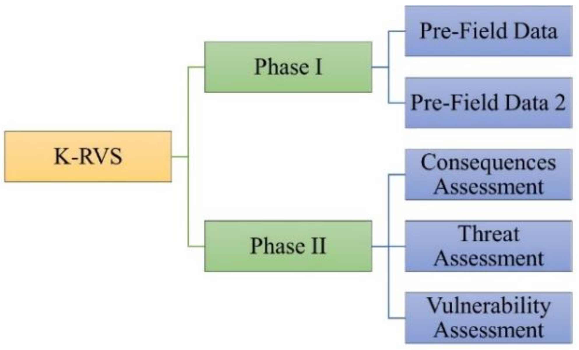
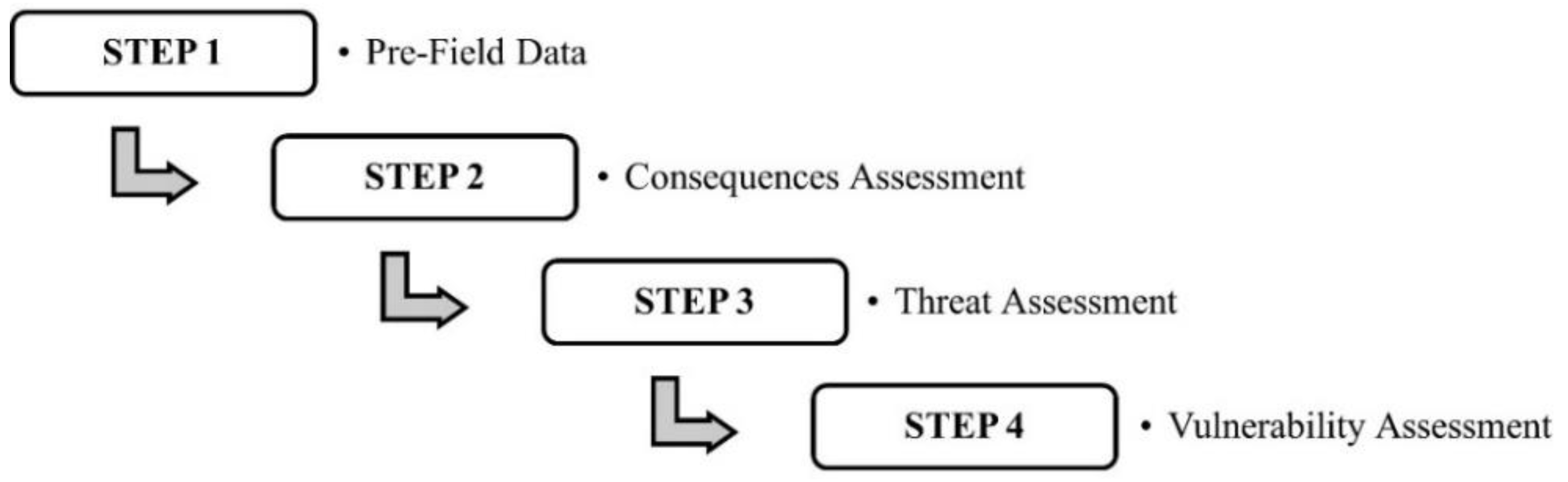
2. Structure of the K-RVS System
2.1. General
2.2. Configuration of Phase I
2.2.1. Pre-Field 1
2.2.2. Pre-Field 2
2.3. Configuration of Phase II
2.3.1. Consequences
2.3.2. Threats
2.3.3. Vulnerability
3. Methodology of the Weight Values
4. Verification and Discussions
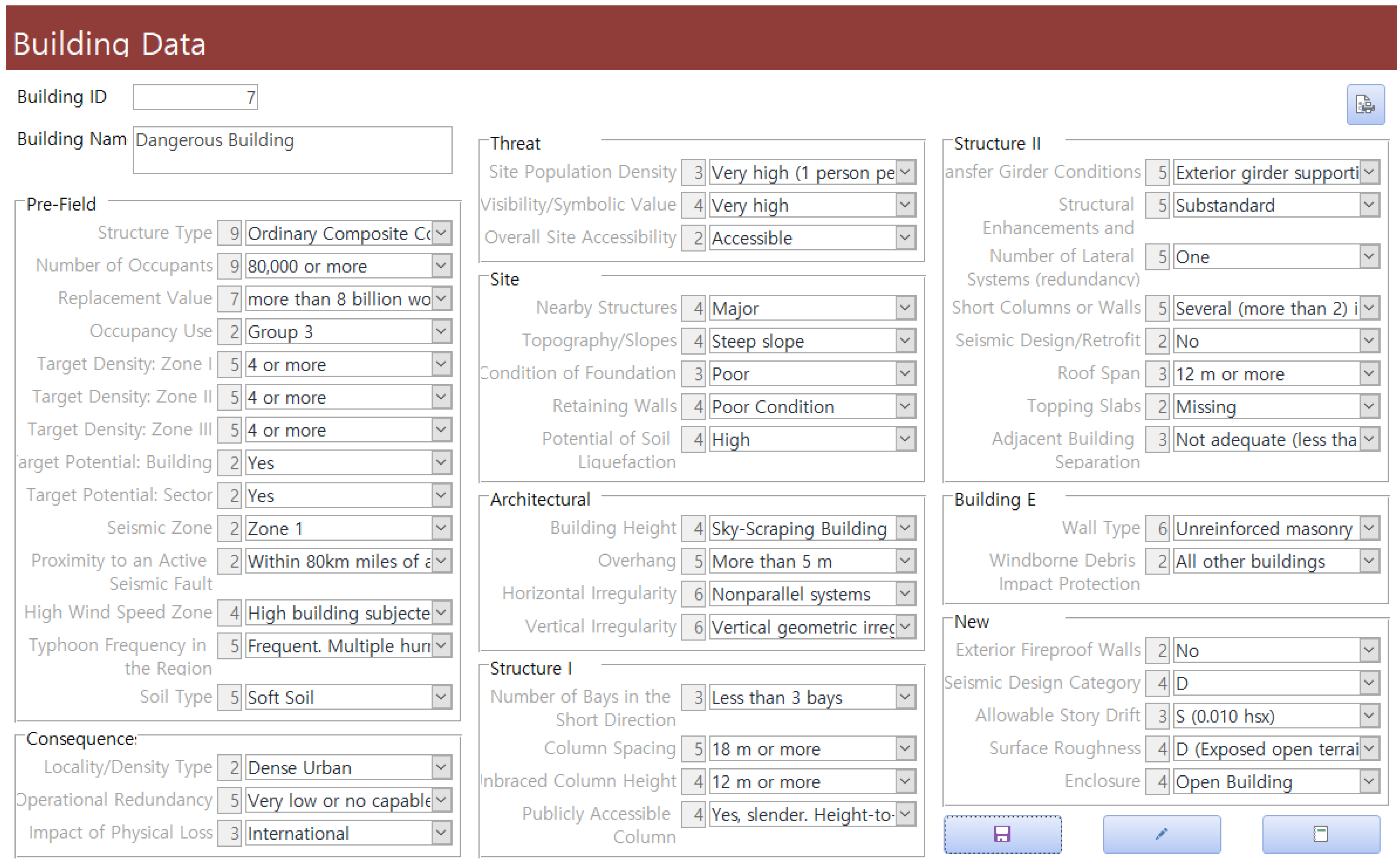
4.1. K-RVS Access System
4.2. Building Examples
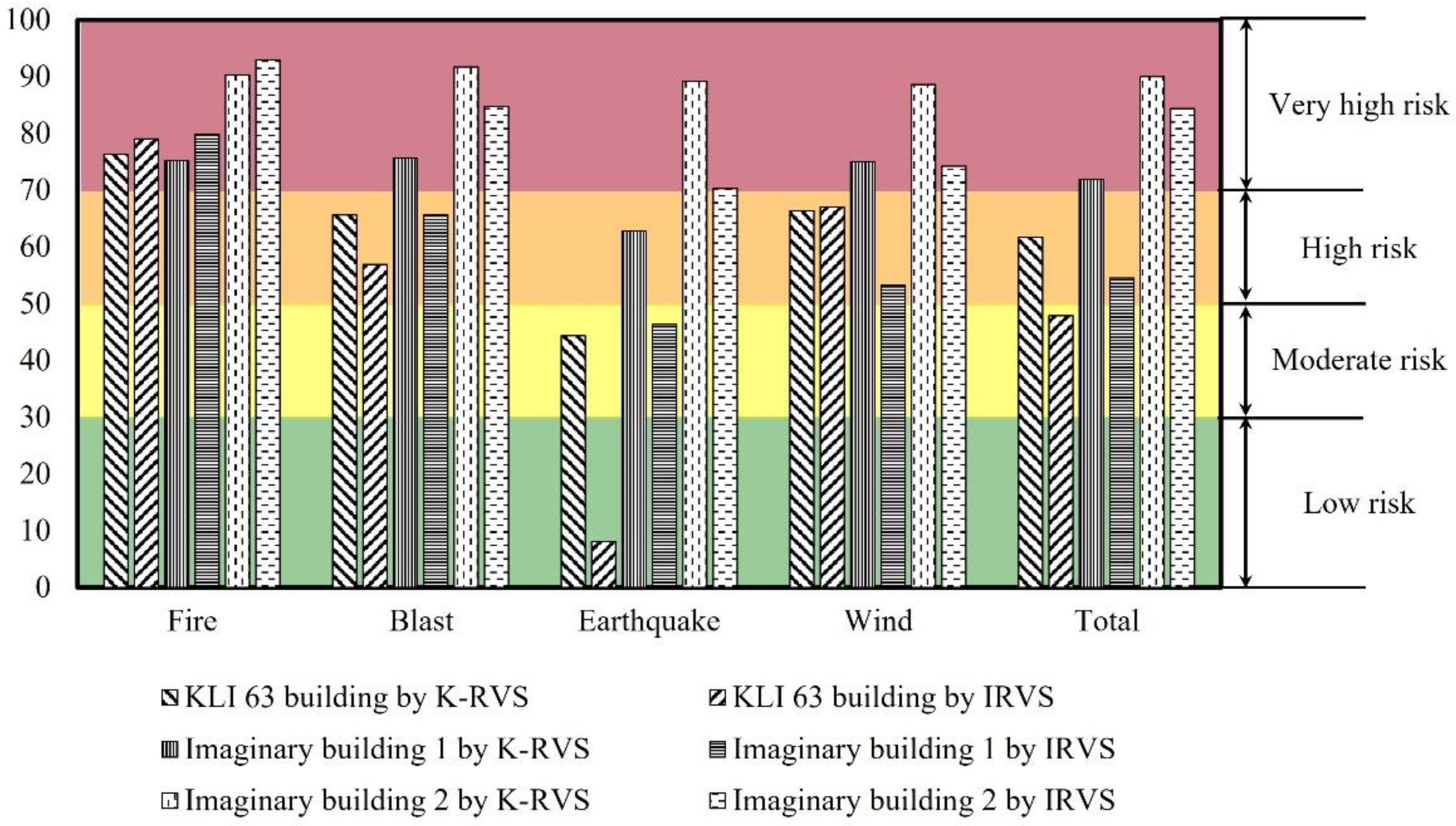
4.3. Results and Discussions
5. Conclusions
Author Contributions
Funding
Institutional Review Board Statement
Informed Consent Statement
Data Availability Statement
Conflicts of Interest
References
- Gerasimidis, S.; Khorasani, N.E.; Garlock, M.; Pantidis, P.; Glassman, J. Resilience of tall steel moment resisting frame buildings with multi-hazard post-event fire. J. Constr. Steel. Res. 2017, 139, 202–219. [Google Scholar] [CrossRef]
- Westen, C.J.V.; Greiving, S. Multi-hazard risk assessment and decision making. In Environmental Hazards Methodologies for Risk Assessment and Management; Dalezios, N.R., Ed.; IWA Publishing: London, UK, 2017; pp. 31–94. [Google Scholar]
- Gentile, R.; Galasso, C.; Idris, Y.; Rusydy, I.; Meilianda, E. From rapid visual survey to multi-hazard risk prioritization and numerical fragility of school buildings. Nat. Hazards Earth. Syst. Sci. 2019, 19, 1365–2019. [Google Scholar] [CrossRef]
- Federal Emergency Management Agency (FEMA). BIPS 04: Integrated Rapid Visual Screening of Buildings; Department of Homeland Security Science and Technology Directorate, Infrastructure Protection and Disaster Management Division (DHS): Washington, DC, USA, 2011. [Google Scholar]
- Federal Emergency Management Agency (FEMA). FEMA 452: A How-To Guide to Mitigate Potential Terrorist Attacks against Buildings; Applied Techonnological Council (ATC): Washington, DC, USA, 2005. [Google Scholar]
- Federal Emergency Management Agency (FEMA). FEMA 454: Designing for Earthquakes, Risk Management Series; Applied Techonnological Council (ATC): Washington, DC, USA, 2006. [Google Scholar]
- Federal Emergency Management Agency (FEMA). FEMA 454: Design Guide for Improving Critical Facility Safety from Flooding and High Winds, Risk Management Series; Applied Techonnological Council (ATC): Washington, DC, USA, 2007. [Google Scholar]
- Federal Emergency Management Agency (FEMA). FEMA 455: Handbook for Rapid Visual Screening of Buildings to Evaluate Terrorism Risk; Applied Techonnological Council (ATC): Washington, DC, USA, 2009. [Google Scholar]
- Federal Emergency Management Agency (FEMA). FEMA P-154: Rapid Visual Screening of Buildings for Potential Seismic Hazards: A Handbook, 3rd ed.; Applied Techonnological Council (ATC): Washington, DC, USA, 2015. [Google Scholar]
- Federal Emergency Management Agency (FEMA). FEMA P-155: Rapid Visual Screening of Buildings for Potential Seismic Hazards: Supporting Documentation, 3rd ed.; Applied Techonnological Council (ATC): Washington, DC, USA, 2015. [Google Scholar]
- Council on Tall Buildings and Urban Habitat (CTBUH). Available online: https://www.skyscrapercenter.com/countries?list=buildings-200 (accessed on 17 March 2022).
- Lee, K.H.; Kim, C.H. The state of terrorism preventive building security design in multi-use building and the role of local governments. Crisisonomy 2009, 5, 44–58. [Google Scholar]
- Kang, K.-Y.; Park, B.-J.; Lee, K.-H. A study on the vulnerability assessment of high rise buildings in Korea for protecting from vehicle bomb attack. J. Arch. Inst. Korea 2011, 27, 125–133. [Google Scholar]
- Yu, Y.S.; Yoon, S.W.; Ju, Y.K. Risk assessment of tall buildings in Korea by comparative study of modified RVS and IRVS system. J. Korean. Assoc. Spat. Struct. 2012, 12, 91–98. [Google Scholar] [CrossRef][Green Version]
- Lee, S.K.; Yoon, S.W. Risk evaluation of wind-induced damage in domestic buildings by IRVS. In Proceedings of the KASS Symposium-Spring 2013, Gwangju, Korea, 24 May 2013. [Google Scholar]
- Kang, K.-Y.; Park, S.-Y.; Heo, H.; Lee, K.-H. Classification of architectural design elements for the risk assessment of bomb attack of multi-use buildings. J. Arch. Inst. Korea 2018, 34, 47–57. [Google Scholar]
- Kang, K.-Y.; Park, S.-Y.; Lee, K.-H. Architectural design practitioners’ perspectives on anti-terrorism design of multi-use buildings. J. Community Saf. Secur. Environ. Des. 2019, 10, 135–168. [Google Scholar] [CrossRef]
- Kim, T.-Y.; Han, G.-S.; Kang, B.-S.; Lee, K.-H. Development of a risk assessment model against disasters in high-rise buildings and results of a building simulation analysis. J. Asian. Archit. Build. 2022, 21, 249–262. [Google Scholar] [CrossRef]
- Kim, T.-Y.; Han, G.-S.; Kang, B.-S.; Lee, K.-H. A study on a risk assessment method and building simulation for the development of a Korean integrated disaster evaluation simulator (K-IDES) for high-rise Buildings. Archit. Res. 2020, 22, 105–112. [Google Scholar]
- Ramirez, M.A.A.P. Disaster Assessment Guideline of Tall Buildings in South Korea by K-Rapid Visual Screening System. Master’s Thesis, Korea University, Seoul, Korea, 2018. [Google Scholar]
- Asprone, D.; Jalayer, F.; Prota, A.; Manfredi, G. Proposal of a probabilistic model for multi-hazard risk assessment of structures in seismic zones subjected to blast for the limit state of collapse. Struct. Saf. 2010, 32, 25–34. [Google Scholar] [CrossRef]
- Kameshwar, S.; Padgett, J.E. Multi-hazard risk assessment of highway bridges subjected to earthquake and hurricane hazards. Eng. Struct. 2014, 78, 154–166. [Google Scholar] [CrossRef]
- Koks, E.E.; Rozenberg, J.; Zorn, C.; Tariverdi, M.; Vousdoukas, M.; Fraser, S.A.; Hall, J.W.; Hallegatte, S. A global multi-hazard risk analysis of road and railway infrastructure assets. Nat. Commun. 2019, 10, 2677. [Google Scholar] [CrossRef] [PubMed]
- Dabbeek, J.; Silva, V. Modeling the residential building stock in the Middle East for multi-hazard risk assessment. Nat. Hazards 2020, 100, 781–810. [Google Scholar] [CrossRef]
- Kwag, S.; Gupta, A.; Baugh, J.; Kim, H.S. Significance of multi-hazard risk in design of buildings under earthquake and wind loads. Eng. Struct. 2021, 243, 112623. [Google Scholar] [CrossRef]
- Wei, L.; Hu, K.; Hu, X.; Wu, C.; Zhang, X. Quantitative multi-hazard risk assessment to buildings in the Jiuzhaigou valley, a world natural heritage site in Western China. Geomat. Nat. Hazards Risk 2022, 13, 193–221. [Google Scholar] [CrossRef]
- MOLIT. Korean Design Standard (in Korean); Ministry of Land, Infrastructure and Transport: Sejong City, Korea, 2019. [Google Scholar]
- Cormie, D.; Mays, G.; Smith, P. Blast Effect on Buildings, 2nd ed.; Thomas Telford Ltd.: London, UK, 2009. [Google Scholar]
- Ali, M.M.; Moon, K.S. Structural developments in tall buildings: Current trends and future prospects. Archit. Sci. Rev. 2007, 50, 205–223. [Google Scholar] [CrossRef]
- Yu, Y.-S. Structural Design Guideline for Mitigating Damages of Explosive Terrorism and Terror Risk Evaluation of High-Rise Buildings in Korea through Modified RVS and IRVS. Master’s Thesis, Korea University, Seoul, Korea, 2013. [Google Scholar]
- Building Act–Statutes of the Republic of Korea. Available online: https://elaw.klri.re.kr/eng_service/lawView.do?hseq=31602&lang=ENG (accessed on 17 March 2022).
- Council on Tall Buildings and Urban Habitat (CTBUH). Available online: https://www.skyscrapercenter.com/building/kli-63-building/891 (accessed on 17 March 2022).


| Phase I | Phase II | |||
|---|---|---|---|---|
| Pre-Field 1 | Pre-Field 2 | Consequences | Threat | Vulnerability |
| Hazard | Number of Occupants | Locality/Density Type | Site Population Density | Nearby Structures |
| Topography/Slopes | ||||
| Replacement Value | Condition of Foundation | |||
| Retaining Walls | ||||
| Occupancy Use | Potential of Soil Liquefaction | |||
| Building Height | ||||
| Target Density: Zone I | Overhang | |||
| Horizontal Irregularity | ||||
| Structure Type | Target Density: Zone II | Operational Redundancy | Visibility/Symbolic Value | Vertical Irregularity |
| Number of Bays in the Short Direction | ||||
| Target Density: Zone III | Column Spacing | |||
| Unbraced Column Height | ||||
| Target Potential: Building | Publicly Accessible Column | |||
| Transfer Girder Conditions | ||||
| Target Potential: Sector | Structural Enhancements and Weaknesses | |||
| Number of Lateral Systems | ||||
| Seismic Zone | Short Columns or Walls | |||
| Seismic Design/Retrofit | ||||
| Resiliency Computations | Proximity to an Active Seismic Fault | Impact of Physical Loss | Overall Site Accessibility | Roof Span |
| Topping Slabs | ||||
| Adjacent Building Separation | ||||
| High Wind Speed Zone | Wall Type | |||
| Windborne Debris Impact Protection | ||||
| Typhoon Frequency in the Region | Exterior Fireproof Walls | |||
| Seismic Design Category | ||||
| Allowable Story Drift | ||||
| Soil Type | Surface Roughness | |||
| Enclosure | ||||
| Pre-Field 1 | IRVS | K-RVS | |
|---|---|---|---|
| Hazard | Earthquake | Earthquake | |
| Flood | |||
| Wind | Wind | ||
| Blast | Blast | ||
| Chemical, biological, and radiological (CBR) | |||
| Fire | Fire | ||
| Structure type | Wood frame | Special reinforced concrete shear wall | |
| Manufactured homes | Ordinary reinforced concrete shear wall | ||
| Steel moment frame | Steel eccentrically braced frame (MRCLC 1) | ||
| Steel eccentrically braced frame (NMRCLC 2) | |||
| Steel braced frame | Special steel concentrically braced frame | ||
| Steel light frame | Ordinary steel concentrically braced frame | ||
| Composite eccentrically braced frame | |||
| Steel frame with cast-in-place concrete shear walls | Special composite concentrically braced frame | ||
| Ordinary composite concentrically braced frame | |||
| Steel frame with unreinforced masonry infill walls | Composite steel plate shear wall | ||
| Special composite shear wall | |||
| Concrete moment frame | Ordinary composite shear wall | ||
| Special steel plate shear wall | |||
| Concrete shear walls | Buckling-restrained braced frame (MRCLC 1) | ||
| Unreinforced masonry bearing walls | Buckling-restrained braced frame (MRCLC 1) | ||
| Concrete frame with unreinforced masonry infill walls | Special reinforced concrete shear wall | ||
| Special steel moment frame | |||
| Intermediate steel moment frame | |||
| Precast concrete tilt-up walls | Ordinary steel moment frame | ||
| Special composite moment frame | |||
| Precast concrete frames with concrete shear walls | Intermediate composite moment frame | ||
| Ordinary composite moment frame | |||
| Reinforced masonry bearing walls with wood or metal deck diaphragms | Composite partially restrained moment frame | ||
| Special reinforced concrete moment frame | |||
| Intermediate reinforced concrete moment frame | |||
| Reinforced masonry bearing walls with precast concrete diaphragms | Ordinary reinforced concrete moment frame | ||
| - | Outrigger structure | Optional/Not from KDS | |
| Tube | |||
| Diagrid | |||
| Exoskeleton | |||
| Space Truss | |||
| Superframe | |||
| Resiliency computations | No resiliency computations are needed | No resiliency computations are needed | |
| General | |||
| Government | General | ||
| Medical | |||
| School K12 | Business/Financial | ||
| Business/Financial | |||
| Retail | Residence | ||
| Pre-Field 2 | IRVS | K-RVS |
|---|---|---|
| Number of occupants | 2000 to less than 5000 | 2000 to less than 4000 |
| 4000 to less than 6000 | ||
| 5000 to less than 10,000 | 6000 to less than 8000 | |
| 8000 to less than 10,000 | ||
| 10,000 to less than 12,500 | 10,000 to less than 20,000 | |
| 12,500 to less than 15,000 | 20,000 to less than 40,000 | |
| 15,000 to less than 17,500 | 40,000 to less than 60,000 | |
| 17,500 to less than 20,000 | 60,000 to less than 80,000 | |
| 20,000 or more | 80,000 or more | |
| Replacement value | $15 m to less than $20 m | less than 60 billion won |
| 60 billion won to less than 80 billion won | ||
| $20 m to less than $150 m | 80 billion won to less than 100 billion won | |
| 100 billion won to less than 200 billion won | ||
| $150 m to less than $400 m | 200 billion won to less than 400 billion won | |
| $400 m to less than $750 m | 400 billion won to less than 600 billion won | |
| $750 m to less than $1 billion | 600 billion won to less than 800 billion won | |
| $1 billion or more | more than 800 billion won | |
| Occupancy use | Group 1 | Other |
| Group 2 | Group 3 | |
| Group 3 | ||
| Target density | Zone 1 | |
| Zone 2 | ||
| Zone 3 | ||
| Target potential | Building | |
| Sector | ||
| Seismic Zone | Low | |
| Medium | ||
| High | ||
| Proximity to an active seismic fault | Farther than 50 miles (80 km) from a fault active or inactive. Or within 50 miles (80 km) of an inactive fault | |
| Within 50 miles (80 km) of an active fault | ||
| High wind speed zone | Low zone with winds of low to moderate speeds- winds below 75 mph (33.5 m/s) peak gust | Low zone with winds of low speeds-winds below 28 m/s or 100 km/h |
| Medium-low zone with winds of moderate speeds-winds below 34 m/s or 120 km/h. | ||
| Medium zone exposed to strong winds- winds between 75 mph (33.5 m/s) and 111 mph (49.6 m/s) peak gust | Medium zone exposed to strong winds- winds between 34 m/s (120 km/h) and 50 m/s (180 km/h). | |
| High building subjected to damaging winds with speeds of greater than 111 mph (49.6 m/s), generally in hurricane-prone or tornado-prone zones. | ||
| Hurricane/typhoon frequency in the region | Never. No record of a hurricane/typhoon in the region | |
| Rare. One or two hurricanes in the last 100 years | Rare. One or two typhoons in the last 70 years | |
| Medium. One or two hurricanes in the last 20 years | Medium Rare. One or two typhoons in the last 40 years | |
| Frequent. Multiple hurricanes in the last 20 years that significantly affected the region | Medium. One or two typhoons in the last 20 years | |
| Frequent. Multiple typhoons in the last 20 years that significantly affected the region | ||
| Soil Type | Hard rock | Hard Rock |
| Rock | ||
| Medium | Very Dense Soil or Soft Rock | |
| Poor | Stiff Soil | |
| Soft Soil | ||
| Consequences | IRVS | K-RVS |
|---|---|---|
| Locality/Density type | Rural/Suburban | Urban |
| Semi urban/Light industrial | ||
| Industrial | Dense Urban | |
| Urban | ||
| Dense Urban | ||
| Operational redundancy | Very high | Very high |
| High | High | |
| Moderate | Moderate | |
| Low | Low | |
| Very low or not capable | Very low or not capable | |
| Impact of physical loss | Local | Regional |
| Statewide | ||
| Regional | National | |
| National | International | |
| International |
| Threat | IRVS | K-RVS |
|---|---|---|
| Site population density | Very low (1 person per 929 m2) | Moderate (1 person per 37 m2) |
| Low (1 person per 93 m2) | ||
| Moderate (1 person per 37 m2) | High (1 person per 3.7 m2) | |
| High (1 person per 3.7 m2) | Very high (1 person per 0.93 m2) | |
| Very high (1 person per 0.93 m2) | ||
| Visibility/Symbolic value | Very low | Low |
| Low | Moderate | |
| Moderate | High | |
| High | Very high | |
| Very high | ||
| Overall site accessibility | Inaccessible | Inaccessible |
| Accessible | Accessible |
| Vulnerability | IRVS | K-RVS | ||
| Nearby structures (Underground or adjacent) | None | |||
| Small | ||||
| Medium | ||||
| Major | ||||
| Topography/Slopes | Flat or terraced with adequate setbacks | |||
| Light slope | ||||
| Moderate slope | ||||
| Steep slope | ||||
| Condition of foundation | Excellent | |||
| Medium | ||||
| Poor | ||||
| Retaining walls | Noon | |||
| Good Condition | ||||
| Moderate Condition | ||||
| Poor Condition | ||||
| Potential of soil liquefaction | None | |||
| Low | ||||
| Medium | ||||
| High | ||||
| Overhang | None | |||
| <5 feet (<1.5 m) | Less than 2 m | |||
| ≥5 feet, <10 feet (1.5–3 m) | From 2 m to less than 3 m | |||
| ≥10 feet, <15 feet (3–4.6 m) | From 3 m to less than 5 m | |||
| ≥15 feet (>4.6 m) | More than 5 m | |||
| Horizontal (plan) irregularity | No. No horizontal irregularities | Torsional irregularity | ||
| Re-entrant corners | ||||
| Diaphragm discontinuity | ||||
| Yes. One or more horizontal irregularities | Out-of-plane offsets | |||
| Nonparallel Systems | ||||
| Vertical irregularity | No. No vertical irregularities | Soft story | ||
| Irregularity | ||||
| Vertical geometric irregularity | ||||
| Yes. One or more vertical irregularities | Irregularity in lateral force-resisting vertical elements | |||
| Discontinuity in strength-weak story | ||||
| Building height | More or equal to 150 feet (>45.7 m) | <12 floors | Intermediate Large-Scale Building (60 m to 120 m) | 15 to 30 floors |
| Less than 200 feet (<61) | 12 to 15 floors | |||
| 200 feet to less than 500 feet (61 m–52.4 m) | 16 to 39 floors | Large Scale Building (120 m to less than 200 m) | 30 to 50 floors | |
| 500 feet to less than 800 feet (152.4–243.8 m) | 40 to 60 floors | High Rise Building (200 m to 300 m) | 50 to 80 floors | |
| 800 feet to less than 1000 feet (243.8–304.8 m) | 60 to 80 floors | Sky-Scraping Building (More than 300 m) | more than 80 floors | |
| More than 1000 feet (>304.8 m) | >80 floors | |||
| Wall type | Cast in place reinforced concrete | |||
| Curtain wall/metal framing | ||||
| Precast panels/reinforced masonry | ||||
| Massive unreinforced masonry | ||||
| Light frame or slender unreinforced masonry (brick) | ||||
| Unreinforced masonry | ||||
| Windborne debris impact protection | Post-benchmark year | |||
| All other buildings | ||||
| Number of bays in the short direction | five or more bays | |||
| three or four bays | ||||
| Less than three bays | ||||
| Column spacing | Less than 15 feet | Less than 4 m | ||
| 15 feet to less than 25 feet | 4 m to less than 8 m | |||
| 25 feet to less than 40 feet | 8 m to less than 12 m | |||
| 40 feet to less than 60 feet | 12 m to less than 18 m | |||
| 60 feet or more | 18 m or more | |||
| Unbraced column height | Less than 12 feet | Less than 4 m | ||
| 12 feet to less than 24 feet | 4 m to less than 8 m | |||
| 24 feet to less than 36 feet | 8 to less than 12 m | |||
| 36 feet or more | 12 m or more | |||
| Publicly accessible column | No publicly accessible columns | |||
| Yes, protected. Behind and separated from the building facade and enclosed by and architectural cover that extends at least 6 inches (15 cm) from face of column | ||||
| Yes, massive. Height-to-width ratio of less than five | ||||
| Yes, slender. Height-to-width ratio of more than five | ||||
| Number of lateral systems (redundancy) | Greater than four | |||
| Four | ||||
| Three | ||||
| Two | ||||
| One | ||||
| Transfer girder conditions | None. All columns are continuous from roof to foundation | |||
| Interior girder supporting one column. The girder spans an interior space and supports one column above | ||||
| Interior girder supporting more than one column. The girder spans an interior space and supports more than one column above | ||||
| Exterior girder supporting one column. The girder is along the perimeter of the building and supports one column above | ||||
| Exterior girder supporting more than one column. The girder is along the perimeter of the building and supports more than one column above | ||||
| Structural enhancements and weaknesses | Hardened. Designed to resist the effects of an explosive attack | |||
| Robust. Designed or retrofit to meet current extreme loading conditions related to high levels of hurricane or earthquake loads or designed to resist progressive collapse | ||||
| None. No structural enhancements or weaknesses in the other attribute options (most common) | ||||
| Marginal. Designed using versions of codes that are no longer considered acceptable for meeting serviceability conditions. Designed using materials or connections that have been shown to perform poorly in abnormal loading situations. Building is not well maintained. | ||||
| Substandard. Designed to a level that has little, if any, reserve strength to withstand any abnormal loads without catastrophic failure. | ||||
| Short columns or walls | None | |||
| Few (one or two) in single floor | ||||
| Several (more than two) in single floor | ||||
| Few (one or two) in several floors | ||||
| Several (more than two) in several floors | ||||
| Seismic design/Retrofit | No | |||
| Yes | ||||
| Roof span | 20 feet or less | 6 m or less | ||
| more than 20 feet to less than 40 feet | more than 6 m to less than 12 m | |||
| 40 feet or more | 12 m or more | |||
| Topping slabs | Present | |||
| Missing | ||||
| Adjacent building separation | No adjacent buildings | |||
| Adequate (more than six inches) | ||||
| Not adequate (less than six inches) | ||||
| Fireproof walls | Not apply | Yes | ||
| No | ||||
| Seismic design category | Not apply | A | ||
| B | ||||
| C | ||||
| D | ||||
| Allowable story drift | Not apply | S (0.010 hsx 1) | ||
| 1 (0.015 hsx 1) | ||||
| 2 (0.020 hsx 1) | ||||
| Surface roughness | Not apply | A (Large city center with closely spaced tall buildings higher than 10-story) | ||
| B (City with closely spaced residential houses with heights of 3.5 m or so or scattered medium rise buildings) | ||||
| C (Open terrain with scattered obstructions with heights of 1.5 to 10 m or so or scattered low-rise buildings) | ||||
| D (Exposed open terrain with few obstructions or scattered obstructions less than 1.5 m in height or grassland, beach, airport, etc.) | ||||
| Enclosure | Not apply | Enclosed | ||
| Partially open/without dominant opening | ||||
| Partially open/with dominant opening | ||||
| Open Building | ||||
| Category | Weight Value (W) |
|---|---|
| Very Highly Important | 100 |
| Highly Important | 80 |
| Very Important | 25 |
| Relevant | 15 |
| Important | 10 |
| Medium Important | 5 |
| Component | No. | Characteristics | Earthquake | Wind | Blast | Fire | |
|---|---|---|---|---|---|---|---|
| Pre-field 1 | 1 | Structure type | 80 | 100 | 80 | 100 | |
| 2 | Number of occupants | 10 | 15 | 15 | 25 | ||
| 3 | Replacement value | 15 | 5 | 15 | 10 | ||
| Pre-field 2 | 4 | Occupancy use | - | - | 15 | 25 | |
| 5 | Target density: Zone I | - | - | 15 | 25 | ||
| 6 | Target density: Zone II | - | - | 15 | 15 | ||
| 7 | Target density: Zone III | - | - | 15 | 15 | ||
| 8 | Target potential: Building | - | - | 25 | 25 | ||
| 9 | Target potential: Sector | - | - | 10 | 25 | ||
| 10 | Seismic zone | 25 | - | - | 10 | ||
| 11 | Proximity to an active seismic fault | 25 | - | - | 10 | ||
| 12 | High wind speed zone | 5 | 10 | - | - | ||
| 13 | Typhoon frequency in the region | - | 25 | - | - | ||
| 14 | Soil type | 25 | - | - | - | ||
| Consequences | 15 | Locality/Density type | 10 | 10 | 10 | 15 | |
| 16 | Operational redundancy | 10 | 10 | 10 | 10 | ||
| 17 | Impact of physical loss | 10 | 10 | 10 | 10 | ||
| Threat | 18 | Site population density | - | - | 10 | 15 | |
| 19 | Symbolic value | - | - | 10 | 15 | ||
| 20 | Overall site accessibility | - | - | 25 | 25 | ||
| Vulnerability | Site | 21 | Nearby structures | 15 | 5 | 15 | 10 |
| 22 | Topography/Slopes | 25 | 25 | 25 | - | ||
| 23 | Condition of foundation | 15 | - | - | - | ||
| 24 | Retaining walls | 10 | 5 | - | - | ||
| 25 | Potential of soil liquefaction | 15 | - | - | - | ||
| Architectural | 26 | Building height | 10 | 15 | 25 | 15 | |
| 27 | Overhang | 10 | 5 | 10 | 5 | ||
| 28 | Horizontal irregularity | 15 | 5 | - | - | ||
| 29 | Vertical irregularity | 15 | 5 | - | - | ||
| Structure | 30 | Number of bays in the short direction | 5 | 5 | 15 | - | |
| 31 | Column spacing | 5 | 5 | 10 | - | ||
| 32 | Unbraced column height | 5 | 5 | 10 | - | ||
| 33 | Publicly accessible column | - | - | 15 | 5 | ||
| 34 | Transfer girder conditions | 25 | 25 | 15 | - | ||
| 35 | Structural enhancements and weaknesses | 5 | 5 | 5 | - | ||
| 36 | Number of lateral systems | 5 | 10 | 5 | - | ||
| 37 | Short columns | 15 | 5 | - | - | ||
| 38 | Seismic retrofit | 25 | 10 | 15 | - | ||
| 39 | Roof span | - | 5 | - | - | ||
| 40 | Topping slabs | 5 | 5 | - | - | ||
| 41 | Building separation | 15 | - | - | - | ||
| Building Enclosure | 42 | Wall type | 5 | 10 | 15 | - | |
| 43 | Windborne debris impact Protection | - | 10 | 10 | - | ||
| New | 44 | Exterior fireproof walls | - | - | 15 | 15 | |
| 45 | Seismic design category | 5 | - | - | - | ||
| 46 | Allowable story drift | 5 | - | - | - | ||
| 47 | Surface roughness | - | 5 | - | 5 | ||
| 48 | Enclosure | - | 5 | - | 15 | ||
| Classification | Scores (S) |
|---|---|
| Very low | 1 |
| Low | 2 |
| Moderate | 3 |
| High | 4 |
| Very High | 5 |
| Color | Final Score (D) | Disaster Assessment |
|---|---|---|
| 0–30% | Low risk | |
| 30–50% | Moderate risk | |
| 50–70% | High risk | |
| 70–100% | Very high risk |
| Component | No. | Characteristics | KLI 63 Building | Imaginary Building 1 | Imaginary Building 2 | ||||
|---|---|---|---|---|---|---|---|---|---|
| IRVS | K-RVS | IRVS | K-RVS | IRVS | K-RVS | ||||
| Pre-field 1 | 1 | Structure type | Steel Moment Frame | Ordinary Steel Moment Frame | Steel Moment Frame | Ordinary Steel Moment Frame | Steel Frame with Unreinforced Infill Walls | Ordinary Steel Concentrically Braced | |
| 2 | Number of occupants | 10,000–12,500 | 10,000–20,000 | 17,500–20,000 | 10,000–20,000 | 17,500–20,000 | 10,000–20,000 | ||
| 3 | Replacement value | $20 M–$150 M | Less than 60 B | $20 M–$150 M | Less than 60 B | $20 M–$150 M | 60 B to less than 80 B | ||
| Pre-field 2 | 4 | Occupancy use | Group 3 | Group 3 | Group 3 | Group 3 | Group 3 | Group 3 | |
| 5 | Target density: Zone I | 2 | 2 | 0 | 0 | >4 | 4 or more | ||
| 6 | Target density: Zone II | 1–3 | 1–3 | 4–6 | 4–7 | >10 | 10 or more | ||
| 7 | Target density: Zone III | 1-6 | 1-6 | 13-19 | 13-19 | >20 | 20 or more | ||
| 8 | Target potential: Building | Yes | Yes | Yes | Yes | Yes | Yes | ||
| 9 | Target potential: Sector | Yes | Yes | No | No | Yes | Yes | ||
| 10 | Seismic zone | Low | Zone 2 | Medium | Zone 2 | High | Zone 1 | ||
| 11 | Proximity to an active seismic fault | Not near fault | Farther than 80 km from a fault | Not Near Fault | Farther than 80 km from a Fault | Near Fault | Within 80 km from a Fault | ||
| 12 | High wind speed zone | Low | Medium-Low Zone | Medium | Medium (Exposed to Strong Winds) | Medium | Medium (Exposed to Strong Winds) | ||
| 13 | Typhoon frequency in the region | Frequent | Frequent | Rare | Medium-Rare | Medium | Medium (1 or 2 in the last 20 years) | ||
| 14 | Soil type | Hard Rock | Hard Rock | Medium | Very Dense Rock | Medium | Stiff Soil | ||
| Consequences | 15 | Locality/Density type | Urban | Urban | Dense Urban | Dense Urban | Dense Urban | Dense Urban | |
| 16 | Operational redundancy | High | High | High | High | Low | Low | ||
| 17 | Impact of physical loss | National | National | Regional | Regional | National | National | ||
| Threat | 18 | Site population density | High | High | High | High | Very High | Very High | |
| 19 | Symbolic value | High | High | High | High | Very High | Very High | ||
| 20 | Overall site accessibility | Accessible | Accessible | Accessible | Accessible | Accessible | Accessible | ||
| Vulnerability | Site | 21 | Nearby structures | None | None | Medium | Medium | Major | Major |
| 22 | Topography/Slopes | Flat | Flat | Moderate Slope | Moderate Slope | Steep | Steep | ||
| 23 | Condition of foundation | Excellent | Excellent | Excellent | Excellent | Poor | Poor | ||
| 24 | Retaining walls | None | None | Moderate Condition | Moderate Condition | Moderate Condition | Moderate Condition | ||
| 25 | Potential of soil liquefaction | Low | Low | Low | Low | Medium | Medium | ||
| Architectural | 26 | Building height | 800–1000 ft (60–80 floors) | High Rise Building (200 m to 300 m) | 200–500 ft | Intermediate Large Scale (60–120 m) | 500–800 ft | High Rise Building (200–300 m) | |
| 27 | Overhang | None | None | 5–10 ft | From 2 m to less than 3 m | >15 ft | More than 5 m | ||
| 28 | Horizontal irregularity | None | None | Yes | Re-Entrant Corners | Yes | Torsional Irregularity | ||
| 29 | Vertical irregularity | None | None | Yes | Irregularity in Lateral Force | Yes | Soft Story | ||
| Structure | 30 | Number of bays in the short direction | 3–5 | 3 or 4 bays | 3–5 | 3 or 4 Bays | <3 | Less than 3 Bays | |
| 31 | Column spacing | 15–25 ft | 4 m to less than 8 m | 15–25 ft | 4 m to less than 8 m | >60 ft | 18 m or More | ||
| 32 | Unbraced column height | 12–24 ft | 4 m to less than 8 m | 24–36 ft | 8 m to less than 12 m | >36 ft | 12 m or more | ||
| 33 | Publicly accessible column | None | None | Yes, Massive | Yes, Massive | Yes, Slender | Yes, Slender | ||
| 34 | Transfer girder conditions | None | None | Int. Girder Sup.1 Column | Int. Girder Sup.1 Column | Ext. Girder Sup. > 1 Column | Ext. Girder Sup. > 1 Column | ||
| 35 | Structural enhancements and weaknesses | None | None | None | None | Marginal | Marginal | ||
| 36 | Number of lateral systems | 1 | One | 3 | Three | 2 | Two | ||
| 37 | Short columns | None | None | Few in a Single Floor | Few in a Single Floor | Few in Several Floors | Few in Several Floors | ||
| 38 | Seismic retrofit | Yes | Yes | No | No | No | No | ||
| 39 | Roof span | ≤20 ft | 6 m or less | >20–<40 ft | More than 6 m less than 12 m | >40 ft | 12 m or more | ||
| 40 | Topping slabs | Present | Present | Present | Present | Missing | Missing | ||
| 41 | Building separation | No adjacent buildings | No adjacent buildings | Adequate | Adequate | Adequate | Adequate | ||
| Building Enclosure | 42 | Wall type | Curtain Wall | Curtain Wall | Light frame | Light frame | Curtain Wall | Curtain Wall | |
| 43 | Windborne debris impact Protection | All other buildings | All other buildings | All Others | All Others | All others | All Others | ||
| New | 44 | Exterior fireproof walls | N/A | Yes | N/A | No | N/A | Yes | |
| 45 | Seismic design category | N/A | B | N/A | A | N/A | B | ||
| 46 | Allowable story drift | N/A | 1 (0.015 hsx) | N/A | 2 (0.020 hsx) | N/A | 2 (0.020 hsx) | ||
| 47 | Surface roughness | N/A | A (large city) | N/A | B | N/A | A (large city) | ||
| 48 | Enclosure | N/A | Partially Open (without dominant opening) | N/A | Partially Open (without dominant opening) | N/A | Enclosed | ||
| Hazards | System | KLI 63 Building | Imaginary Building 1 | Imaginary Building 2 |
|---|---|---|---|---|
| Fire | K-RVS | 76.32 | 75.17 | 90.34 |
| IRVS | 79.06 | 79.84 | 92.93 | |
| Blast | K-RVS | 65.57 | 75.67 | 91.75 |
| IRVS | 56.93 | 65.63 | 84.75 | |
| Earthquake | K-RVS | 44.30 | 62.80 | 89.25 |
| IRVS | 8.08 | 46.35 | 70.26 | |
| Wind | K-RVS | 66.39 | 75.00 | 88.61 |
| IRVS | 67.02 | 53.31 | 74.25 | |
| Total | K-RVS | 61.70 | 71.86 | 90.03 |
| IRVS | 47.85 | 54.49 | 84.38 |
Publisher’s Note: MDPI stays neutral with regard to jurisdictional claims in published maps and institutional affiliations. |
© 2022 by the authors. Licensee MDPI, Basel, Switzerland. This article is an open access article distributed under the terms and conditions of the Creative Commons Attribution (CC BY) license (https://creativecommons.org/licenses/by/4.0/).
Share and Cite
Park, M.J.; Ju, Y.K. Disaster Assessment of Tall Buildings in Korea by K-Rapid Visual Screening System Focusing on Structural Safety. Buildings 2022, 12, 442. https://doi.org/10.3390/buildings12040442
Park MJ, Ju YK. Disaster Assessment of Tall Buildings in Korea by K-Rapid Visual Screening System Focusing on Structural Safety. Buildings. 2022; 12(4):442. https://doi.org/10.3390/buildings12040442
Chicago/Turabian StylePark, Min Jae, and Young K. Ju. 2022. "Disaster Assessment of Tall Buildings in Korea by K-Rapid Visual Screening System Focusing on Structural Safety" Buildings 12, no. 4: 442. https://doi.org/10.3390/buildings12040442
APA StylePark, M. J., & Ju, Y. K. (2022). Disaster Assessment of Tall Buildings in Korea by K-Rapid Visual Screening System Focusing on Structural Safety. Buildings, 12(4), 442. https://doi.org/10.3390/buildings12040442