Abstract
The shake table test is one of the preferred techniques used to understand the dynamic response of a structure. However, due to the limited number of facilities available to perform such tests and their expensiveness, researchers often must rely on numerical models validated with the results of the static tests only. Moreover, most research papers concerning shake table tests lack details on how the tests were planned and executed. This paper explains the steps used for the preparation and execution of shake table tests on three reduced-scale buildings. These buildings were constructed outside the shake table surface, on a metallic base frame, and later moved to the shake table used for the tests in order to optimize the time of the experimental campaign. This approach enabled us to complete the tests in only 6 days. The approach presented in this paper may be helpful to researchers who want to increase the effectiveness of the available shake table facility and overcome the limitations of time and budget. Moreover, the solution presented in this article helps in the displacement of specimens without the use of a crane or other sophisticated hydraulic machinery. Thus, it could also be useful for testing specimens that have been aged and that are sensitive to displacements.
1. Introduction
Numerical models are a cost-efficient and convenient tool for the determination of the dynamic behavior of a structure. However, they require proper validation supported by experimental results. They are often validated at a material scale [1] and, sometimes, just with the numerical reference model [2]. The validation of material behavior is the first step in numerical modeling as it helps in performing structural and system-level simulations. The numerical models that have been validated with the help of experimental test results at the wall structural level are important to understanding the in-plane behavior of a structure [3,4,5,6]. A numerical 3D model of a masonry building with different configurations was investigated to simulate failure propagation using a refined DEM model, which helped in understanding the influence of the thickness of a bearing wall on preventing the failure of the roof [7]. Several numerical model studies have been carried out and validated using experimental results at the material and structural scales, but only a few models have been validated at the system level. A numerical model validated with multi-scale experimental tests (material, structural, and system scales) [8,9,10] is a powerful tool for parametric analyses. A calibrated numerical model is beneficial in understanding the behavior of a structure and estimating the performance to generate a fragility curve [11,12]. Detailed experimental analysis of structures, including the characterization of dynamic properties, has become vital to the refinement of the finite-element model, which is used to carry out vulnerability analyses of structures [13]. The numerical model is also helpful for performing vulnerability risk assessments by comparing the same structural systems under two or more different sets of seismic site conditions [14]. All these numerical models are reliable tools for studying the vulnerability and fragility of structures provided that the models are validated using proper experimental test results.
An experimental test at the system level is important but challenging to carry out due to the limited availability of facilities, the high cost, and the large amount of time consumed. The shake table test is a great tool for understanding the seismic performance of structures under realistic earthquake conditions. However, experimental tests with shake tables are rarely performed because of the limited availability of the facilities and their cost. A low-cost shake table with the dimensions of 1.5 m × 2.0 m was built for 45,000 USD [15], and a shake table with a larger size of 2.5 m × 3.5 m was built for slightly less than 250,000 EUR [16]. Hence, even for the cheapest shake tables, the cost investment is significant. Therefore, the optimal utilization of such a testing apparatus is necessary. Other seismic simulation tools, such as shock tables and harmonic shake tables, can also be used by developing countries to understand the seismic performance of vernacular buildings [17]. Another alternative to shake tables is real-time hybrid simulation, in which physical and numerical models are combined in order to evaluate the overall performance of the structure [18,19]. For a hybrid simulation test, a constitutive law for the behavior of the structure is required for the numerical model, which can be challenging to obtain for vernacular structures. Therefore, for such structures, more detailed tests using a shake or shock table are necessary.
Dynamic shake table tests are performed on various structures built using concrete, wooden, steel, brick, or other composite materials. Structures that do not require a curing period, such as a steel frame structure, can be directly assembled on the shake table [20]. However, masonry structures require a curing period, and due to the availability of shake tables, these specimens cannot be built on the table surface. Moreover, these structures are sensitive to displacements. Therefore, proper construction methods and displacement of the specimen up to the shake table are necessary for these structures, which are the focus of this article.
Different studies on these problems can be found in the literature. A single half-scale stone masonry structure was constructed on a rigid steel base connected to a shake table [21]. Three dry stone masonry models scaled by a factor of 0.55 were constructed outside the shake table on a concrete base frame simultaneously [22], but the process of moving those structures up to the shake table was not reported. A similar concrete base was used to construct two 1:3 reduced-scale adobe models [23]; the displacement of the model up to the table was performed using a forklift, and the final lifting and placement of the models on the table were performed with the help of an overhead crane. The safe shifting of specimens is crucial in order to prevent damage when placing them on the shake table.
In some cases, the mass of the constructed model and the base support can become too large for the mounted crane to handle. Hence, a 1:6 scale model of a bell tower with dimensions of 3.54 m × 3.54 m was directly assembled on a steel frame base and then fixed to the shaking table due to its complex connection details and weight, including the additional mass measuring 8.8 tons [24]. In another research study, a 1:3 reduced-scale stone masonry model, weighing more than 6 tons, was directly built on the shake table [25].
2. Need for and Scope of Work
Cost and time are the two most commonly used indicators when measuring any system’s effectiveness [26]. Therefore, the effectiveness of the shake table test can be optimized by proper planning and execution of the test.
The scale of the model to be tested under a dynamic test is limited by the size of the shake table and the capacity of the hydraulic jack (in terms of force, velocity, and displacement limits). Apart from the technical limitations of the shake table itself, there are other limitations, such as the availability of scaled-down material, a connection, time for the construction of the model, and the mass of the built model. This is why several dynamic tests on shake tables have been performed with a reduced-scale model. Still, there remains a lack of information on how to optimize the use time of the shake table and the mechanism of the placement of specimens on the shake table. This paper presents a detailed method regarding the setup of the shake table test for three building models built simultaneously and later moved onto the shake table for dynamic testing as part of Ph.D. research work [27]. This article focuses on the challenge of limiting the shake table utilization time in case the sample needs time to be built and is heavy (difficult to move), such as in the case of a building test.
3. Shake Table Specifications
The uniaxial shake table available at Forȇt Cellulose Bois-construction Ameublement (FCBA), Bordeaux, France was used to carry out the dynamic test. It was operated using a 250 kN servo-hydraulic actuator. The surface area of the shake table is 6 × 6 m2. The shake table’s maximum acceleration, velocity, and displacement capacity are 4 g (with a payload mass of 5 tons), 0.75 m/s, and ±0.125 m, respectively. The spacing between the connecting grid points on the table surface is 250 mm, which must be considered when connecting the samples to the shake table.
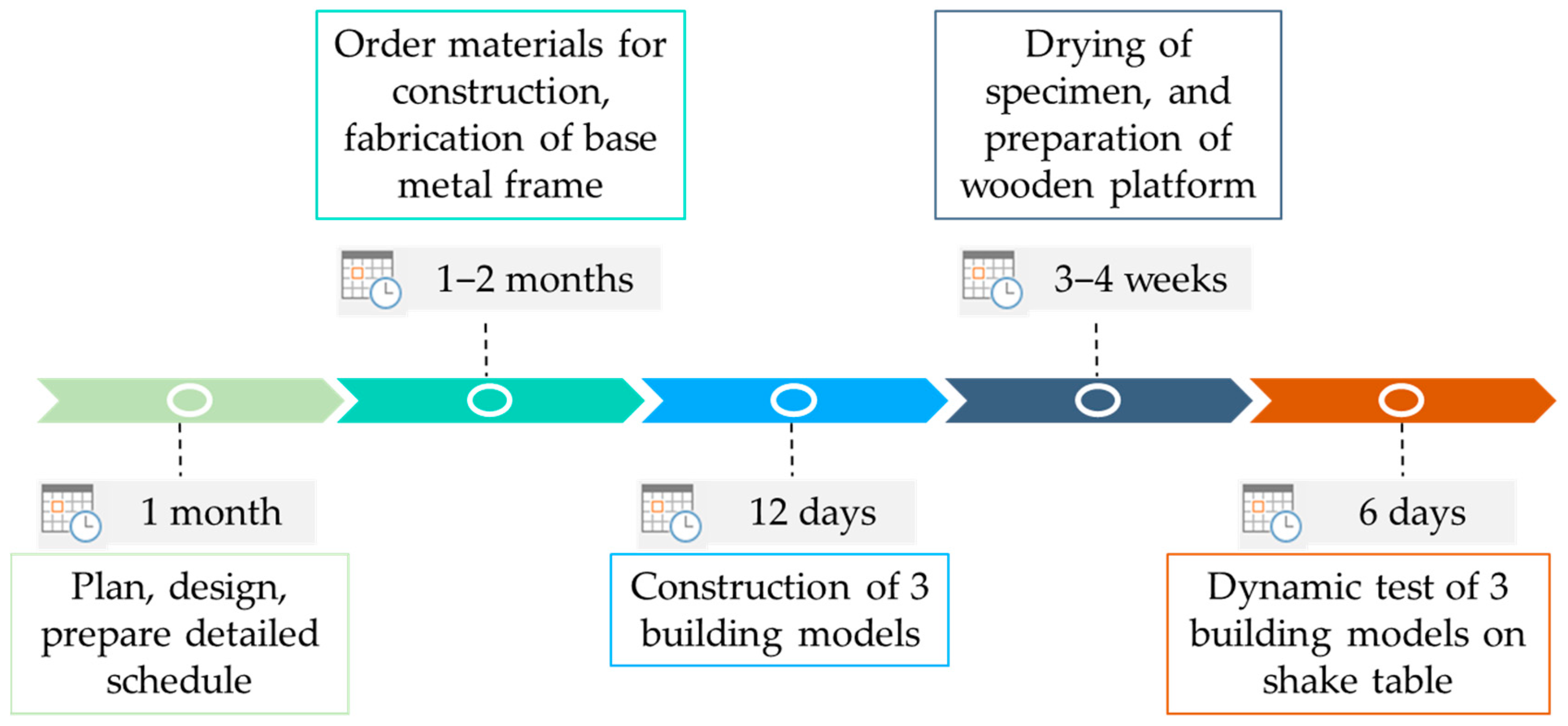
Three 1:2 reduced-scale adobe masonry structures had to be tested under dynamic loading conditions. The average mass of each structure was approximately 4 tons, which is too large for the gantry crane that is available on site. Therefore, a new approach was adopted to make the test possible. Figure 1 presents the timeline for the various stages of the planning, construction, and execution of the dynamic tests. The planning of the dynamic tests and the purchase of construction materials were the steps that took the most time. The construction of the three reduced-scale buildings was completed in 12 days. Afterward, they were left to dry at the temperature of 23 ± 2 °C and a relative humidity of 50 ± 5%. The final dynamic tests were completed in 6 days. Therefore, the shake table was occupied only during those six days. Details of the construction strategies and specimen displacement mechanisms are given in the following section.

Figure 1.
Timelines of the planning, construction, and execution of the dynamic tests.
4. Metallic Base Frame
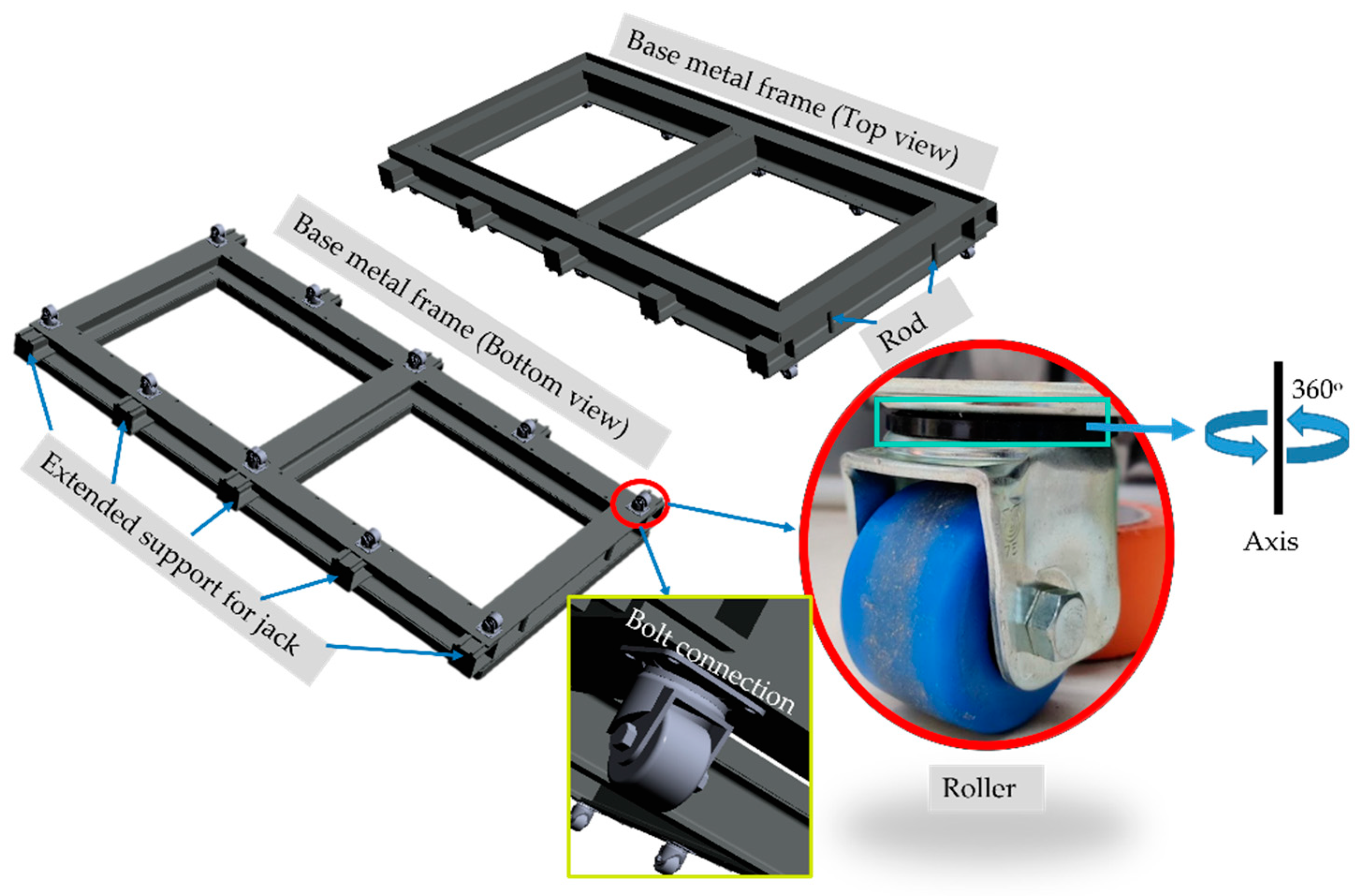
The dimensions of the reduced-scale buildings were adopted from the reconstruction guideline of Nepal [28]. The external dimensions of the 1:2 reduced-scale two-room building model were 3230 mm × 1575 mm. Three metallic base frames made with HEB180 beams were manufactured for their construction. The size of the beam was selected to match the thickness of the wall, which was 175 mm. A bending moment and deflection check was conducted for the selected beam by considering the maximum potential dead load. The base frame’s dimensions were chosen in order to easily fix it to the shake table with bolt connections. During the shake table test, this metallic base frame works as a part of the shake table. However, the maximum operating acceleration, velocity, and displacement limit of the shake table are influenced by the dead mass contributed by the metallic base frame, which needs to be considered in the total payload. Top and bottom views of the metallic base frame are shown in Figure 2. The layout of the base frame corresponds to that of the model building. Metallic plates (50 mm in height) were welded onto the top part of the frame. They were used for the construction of the base of the structure. On the bottom part of the frame, 10 roller positions were designed as shown in Figure 2. The model ‘CKZJ75-N’ from MiSUMi [29] was used with each roller having a maximum load capacity of 600 kg. Each roller has 360° of rotational flexibility about the vertical axis (see Figure 2) and helps to displace the building model smoothly onto the floor surface. The rollers were connected to the base metallic plate using bolt connections. The type of roller was chosen to be adequate for the total mass of the structure and the rugosity of the floor. The metallic base frame has extended support parts on each side of the longer side as shown in Figure 2. They are used to position and operate hydraulic jacks for cars. Two metallic rods were welded onto the external side of the shorter-length side. They are used to tie a cable while displacing the building model.

Figure 2.
Metallic frame used at the base of the building model.
Reduced-scale extruded adobe brick was used with mud mortar to construct three building models: one without a band, one with a timber seismic band, and one with a reinforced concrete band. The schedule for building construction was planned such that the construction of all the buildings could be carried out simultaneously on the metallic frame placed on the laboratory floor. The construction started by casting 25 mm of plain concrete on the metallic frame as shown in Figure 3a. The remaining millimeters of the metallic beam flange were used to lay the first layer of brick so that sliding at the interface between the concrete and the first mortar joint could be prevented during the test. For the construction of the buildings, the metallic frame did not lay on the floor but on timber parts to allow for its elevation for the displacement of the samples (Figure 3b).
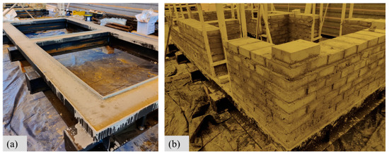
Figure 3.
(a) Plain concrete cast on the metallic frame; (b) bricklaying for the building model.
5. Wooden Platform
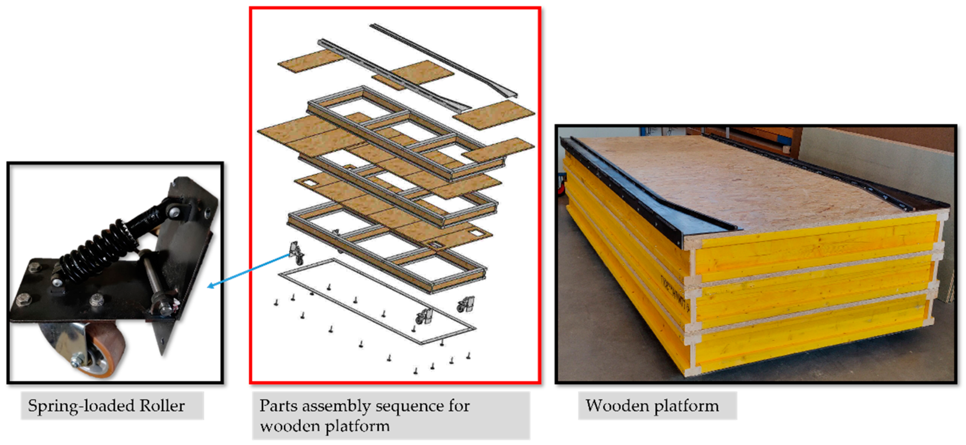
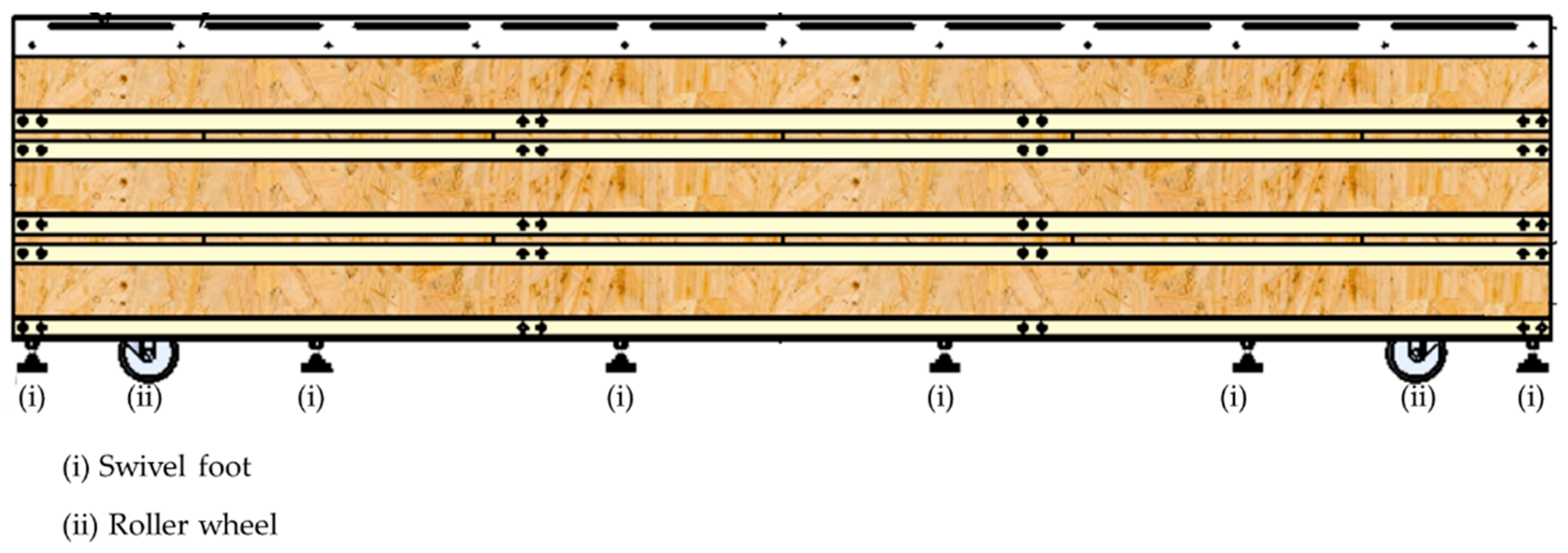
A wooden platform was designed to roll the models onto the shake table easily. To make this possible, its height matched the height of the table. The maximum dead load for this experimental work was 4.8 tons, which was used for the selection of platform components. The additional factor of safety was taken into consideration as this platform is reusable. The wooden platform was built using timber beam and Oriented Strand Board (OSB) panels as shown in Figure 4. It consists of four spring-loaded rollers placed at the corners, three layers of timber beams, and OSB panels placed over each level of timber beams. The model ‘L600.B90.125’ from MiSUMi was used with each roller. The assembly sequence is shown in Figure 4. Two metallic rails were screwed onto the top of the platform to guide the roller of the metallic base frame while moving the building model onto the shake table. The spring-loaded rollers shown in Figure 4. are designed to allow one to move the empty platform. When the building is on the platform, its dead load makes the rollers vanish to help keep the whole platform stable. The entire load is finally supported with the help of 16 swivel foot steel components (model: K0742.006514X75) placed on the bottom layer as shown in the part assembly sequence (see Figure 5). The maximum static load capacity of each swivel foot steel component is 20 kN.

Figure 4.
Wooden platform components and assembly sequence.
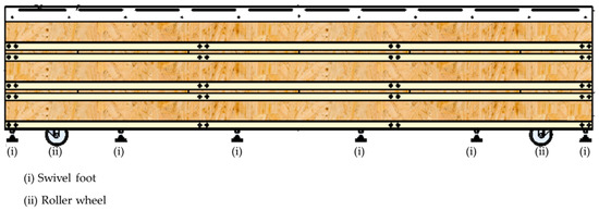
Figure 5.
Side view of the wooden platform.
6. Building Displacement Sequence
The building models were conserved for three weeks before being moved onto the shake table. The sequences used for transferring the building model from the floor to the shake table are as follows:
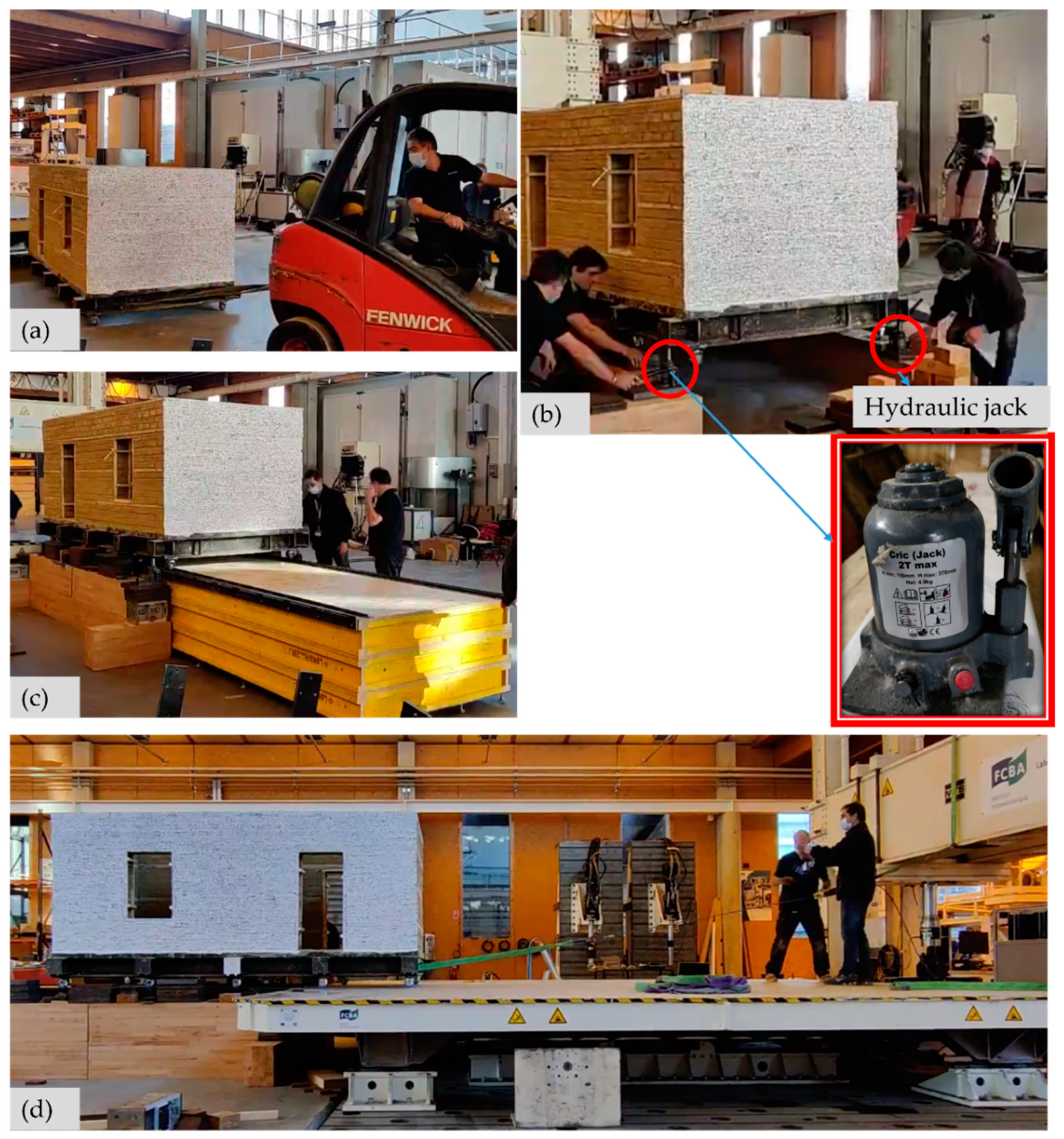
- The metallic base frame was gently elevated from the floor to remove the supporting timber parts and to place the ten rollers (see Figure 2) at the bottom of the frame. To do that, four hydraulic jacks (see Figure 6) were used at each corner of the building simultaneously to prevent any damage to the structure;
 Figure 6. (a) Moving the building on the floor; (b) elevating the building using hydraulic car jacks and timber blocks; (c) placement of the wooden platform; (d) moving the building onto the shake table.
 - Once the model on its rollers was placed on the floor, a weight-lifting belt was passed through the metallic rod (shown in Figure 2) and connected to a forklift truck, as shown in Figure 6a. The static frictional force required to move the model was calculated assuming a frictional coefficient of 0.6 between the rubber and the concrete floor. For a maximum dead load of 4.8 tons, the force required to move the model is 2.88 tons. This calculated force was required when designing the rod parts in the metallic frame (see Figure 2) and in the selection of the weight-lifting belt. With the help of the forklift truck, the building model was moved close to the shake table and aligned parallel to it;
- The next step was to lift the model building vertically and to elevate it high enough to place the wooden platform under it. To elevate the building model, initially, four farm jacks, each with a maximum capacity of 3 tons, were used. However, this approach was not effective due to the lack of stability of the farm jacks for displacement intervals of 20 mm for each lift. Therefore, to improve this process, four hydraulic car jacks, each with a capacity of 2 tons, were used to elevate the building models vertically. The four hydraulic jacks were placed at the four external metal supports. The elevation operation was manually synchronized by counting the pumps (see Figure 6b). The building was elevated in steps of 3–4 cm on all sides simultaneously, and timber blocks were placed under the extended metallic support (see Figure 2) to hold the building in position before beginning each new elevation cycle. Timber blocks were used for security (if one jack had a problem, the building fell only a few centimeters) and because of the limited vertical displacement of the hydraulic car jacks;
- Once the building model was elevated enough to be slightly higher than the shake table site, the wooden platform was placed under the building model, as shown in Figure 6c. The rollers’ alignment was checked before releasing the hydraulic jacks and putting the building model on the wooden platform;
- The building model was finally rolled onto the shake table using the weight-lifting belt attached to the metallic rod on the base frame and pulled using two manual cable pulling sets (also known as come-alongs), as shown in Figure 6d;
- The position of the metallic frame was adjusted to fix the base frame on the table before removing the rollers. All the base rollers were removed using a similar approach as in Stage 1 (see Figure 7a). The metallic frame was fixed to the shake table using 12 bolts. To decrease the total mass during displacement, the roof was assembled on the building only after securely fixing the building to the shake table, as shown in Figure 7b.
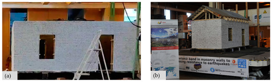 Figure 7. (a) Positioning of the metal frame to fix it to the shake table; (b) roof installation on the building.
The timelapse video shown in the Supplementary Materials is also compiled demonstrating each stages of preparation and the steps for displacing the specimen [30].
7. Conclusions and Recommendation
Details of the experimental preparation and setup for shake table tests are presented in this paper. With the innovative idea of developing a metallic base frame and wooden platform to move the building model onto the shake table, the total cost and time of the experimental campaign were minimized. The total mass of the model and the dimensions of the structures were selected depending on the payload capacity of the shake table. For the design of the metallic base frame, the thickness of the wall, the boundary conditions, and the model’s total mass were considered. The metallic base frame was firmly connected to the shake table platform and did not influence the test results of the structure being tested. However, the mass of the metallic base frame contributed to the total payload of the system, which influences the maximum operating limit of the shake table. The construction of the three building models was completed in two weeks using the metallic base frames. The placement of the building model on the shake table, the connection of measurement sensors, and the carrying out of dynamic tests took two days for each building model. Therefore, the shake table was only required for six days to complete the three reduced-scale building model tests. Hence, the idea of constructing the building structure outside the shake table and moving it onto the table just before the test helps to optimize the shake table utilization time and increase its effectiveness by allowing for several tests in a short period of time. Additionally, the metallic base frame and wooden platform can be reused for future tests for various building typologies, as needed.
Supplementary Materials
A video demonstrating each step of the building’s displacement can be downloaded at: https://cloud.univ-grenoble-alpes.fr/index.php/s/bsNnDX4zpEyr4yK (accessed on 20 February 2022).
Author Contributions
Conceptualization, S.Y., Y.S. and L.D.; methodology, S.Y. and Y.S.; investigation, S.Y., Y.S., F.V.-C. and D.D.; writing—original draft preparation, S.Y.; writing—review and editing, S.Y., Y.S., F.V.-C., L.D., D.D., Y.M. and P.G.; visualization, S.Y.; supervision, Y.S., F.V.-C., Y.M. and P.G. All authors have read and agreed to the published version of the manuscript.
Funding
This work was realized within the framework of LABEX AE & CC and IDEX CDP Risk at Université Grenoble Alpes as part of the program “Investissements d’Avenir” overseen by the French National Research Agency (reference: ANR-15-IDEX-02).
Institutional Review Board Statement
Not applicable.
Acknowledgments
The authors would like to thank Patrice Garcia, Jean-Baptiste Castaing, and Laurent Munier and acknowledge other technical teams from FCBA Bordeaux for their support during the planning and execution stages of the tests. The authors are also grateful for the support provided by Grenoble INP, É-CoLoS, Majid Hajmirababa (Architect), Luis Arléo (Architect), and five Master’s degree students (Antoine Blanche, Mustafa Shuweihdi, Rachel Gonzalez Columbie, Robin Tari, and Sami Labidi) from PhITEM-UGA, who helped during the preparation of the three building samples.
Conflicts of Interest
The authors declare that they have no known competing financial interests or personal relationships that could have influenced the work reported in this paper.
References
- Adhikari, R.K.; D’Ayala, D. Numerical Seismic Performance Assessment of Pre-Earthquake Stone Masonry Residential Building Typology in Light of 2015 Nepal Earthquake. In Proceedings of the Society for Earthquake and Civil Engineering Dynamics Conference (SECED), London, UK, 9–10 September 2019. [Google Scholar]
- Ortega, J.; Vasconcelos, G.; Rodrigues, H.; Correia, M. Assessment of the efficiency of traditional earthquake resistant techniques for vernacular architecture. Eng. Struct. 2018, 173, 1–27. [Google Scholar] [CrossRef]
- Ponte, M.; Milosevic, J.; Bento, R. Parametrical study of rubble stone masonry panels through numerical modelling of the in-plane behaviour. Bull. Earthq. Eng. 2019, 17, 1553–1574. [Google Scholar] [CrossRef]
- Damerji, H.; Yadav, S.; Sieffert, Y.; Vieux-champagne, F.; Malecot, Y. Damage investigation of adobe walls using numerical simulations. In Proceedings of the 7th ECCOMAS Thematic Conference on Computational Methods in Structural Dynamics and Earthquake Engineering, Crete, Greece, 24–26 June 2019. [Google Scholar]
- Reyes, J.C.; Smith-Pardo, J.P.; Yamin, L.E.; Galvis, F.A.; Sandoval, J.D.; Gonzalez, C.D.; Correal, J.F. In-plane seismic behavior of full-scale earthen walls with openings retrofitted with timber elements and vertical tensors. Bull. Earthq. Eng. 2019, 17, 4193–4215. [Google Scholar] [CrossRef]
- Howlader, M.K.; Masia, M.J.; Griffith, M.C. Numerical analysis and parametric study of unreinforced masonry walls with arch openings under lateral in-plane loading. Eng. Struct. 2020, 208, 110337. [Google Scholar] [CrossRef]
- Furukawa, A.; Kiyono, J.; Toki, K. Numerical Simulation of the Failure Propagation of Masonry Buildings during an Earthquake. J. Nat. Disaster Sci. 2012, 33, 11–36. [Google Scholar] [CrossRef] [Green Version]
- Vieux-Champagne, F.; Sieffert, Y.; Grange, S.; Polastri, A.; Ceccotti, A.; Daudeville, L. Experimental analysis of seismic resistance of timber-framed structures with stones and earth infill. Eng. Struct. 2014, 69, 102–115. [Google Scholar] [CrossRef]
- Vieux-Champagne, F.; Sieffert, Y.; Grange, S.; Belinga Nko’ol, C.; Bertrand, E.; Duccini, J.C.; Faye, C.; Daudeville, L. Experimental analysis of a shake table test of timber-Framed structures with stone and earth infill. Earthq. Spectra 2017, 33, 1075–1100. [Google Scholar] [CrossRef]
- Decret, D. Numerical Model for the Assessment of the Seismic Vulnerability of Traditional Masonry Structures with Seismic Bands. Ph.D. Thesis, Université Grenoble Alpes, Grenoble, France, 2021. [Google Scholar]
- Flora, A.; Perrone, G.; Cardone, D. Evaluating collapse fragility curves for existing buildings retrofitted using seismic isolation. Appl. Sci. 2020, 10, 2844. [Google Scholar] [CrossRef] [Green Version]
- Maharjan, A.; Parajuli, H.R. Seismic Performance Evaluation of Stone Masonry Houses Constructed with Reinforced Concrete Bands. Nepal J. Sci. Technol. 2020, 19, 204–214. [Google Scholar] [CrossRef]
- Saitta, F.; Clemente, P.; Buffarini, G.; Bongiovanni, G. Vulnerability Analysis and Seismic Retrofit of a Strategic Building. J. Perform. Constr. Facil. 2017, 31, 04016085. [Google Scholar] [CrossRef]
- Ponzo, F.C.; Di Cesare, A.; Telesca, A.; Pavese, A.; Furinghetti, M. Advanced modelling and risk analysis of RC buildings with sliding isolation systems designed by the Italian seismic code. Appl. Sci. 2021, 11, 1938. [Google Scholar] [CrossRef]
- Baran, T.; Tanrikulu, A.K.; Dundar, C.; Tanrikulu, A.H. Construction and performance test of a low-cost shake table. Exp. Tech. 2011, 35, 8–16. [Google Scholar] [CrossRef]
- Damerji, H.; Yadav, S.; Sieffert, Y.; Debove, L.; Vieux-champagne, F.; Malecot, Y. Design of a Shake Table with Moderate Cost. Exp. Tech. 2021. [Google Scholar] [CrossRef]
- Bothara, J.; Desai, R.; Ingham, J.; Dizhur, D. Seismic simulation tools and methods appropriate for developing countries. Structures 2021, 34, 314–326. [Google Scholar] [CrossRef]
- Calabrese, A.; Strano, S.; Terzo, M. Real-time hybrid simulations vs shaking table tests: Case study of a fibre-reinforced bearings isolated building under seismic loading. Struct. Control Health Monit. 2014, 22, 535–556. [Google Scholar] [CrossRef]
- Furinghetti, M.; Lanese, I.; Pavese, A. Experimental Assessment of the Seismic Response of a Base-Isolated Building Through a Hybrid Simulation Technique. Front. Built Environ. 2020, 6, 33. [Google Scholar] [CrossRef]
- Zhang, C.; Jiang, N. A shaking table real-time substructure experiment of an equipment–structure–soil interaction system. Adv. Mech. Eng. 2017, 9, 1–12. [Google Scholar] [CrossRef] [Green Version]
- Mouzakis, C.; Adami, C.; Karapitta, L.; Vintzileou, E. Seismic behaviour of timber-laced stone masonry buildings before and after interventions: Shaking table tests on a two-storey masonry model. Bull. Earthq. Eng. 2018, 16, 803–829. [Google Scholar] [CrossRef]
- Wang, M.; Liu, K.; Guragain, R.; Shrestha, H.; Ma, X. Shake table tests on the two-storey dry-joint stone masonry structures reinforced with timber laces and steel wires. Bull. Earthq. Eng. 2018, 17, 2199–2218. [Google Scholar] [CrossRef]
- Khan, F.Z.; Ahmad, M.E.; Ahmad, N. Shake table testing of confined adobe masonry structures. Earthq. Struct. 2021, 20, 149–160. [Google Scholar] [CrossRef]
- Xie, Q.; Wang, L.; Zhang, L.; Hu, W.; Zhou, T. Seismic behaviour of a traditional timber structure: Shaking table tests, energy dissipation mechanism and damage assessment model. Bull. Earthq. Eng. 2018, 17, 1689–1714. [Google Scholar] [CrossRef]
- Rafi, M.M.; Lodi, S.H.; Qazi, S.A.; Kumar, A.; Verjee, F. Seismic response of reduced scale stone masonry building. Proc. Inst. Civil Eng. Struct. Build. 2018, 171, 528–541. [Google Scholar] [CrossRef]
- Sundqvist, E.; Backlund, F.; Chronéer, D. What is Project Efficiency and Effectiveness? Procedia Soc. Behav. Sci. 2014, 119, 278–287. [Google Scholar] [CrossRef] [Green Version]
- Yadav, S. Experimental Analysis of the Seismic Vulnerability of Earth Masonry Reinforced with Horizontal Bands. Ph.D. Thesis, Université Grenoble Alpes, Grenoble, France, 2021. [Google Scholar]
- DUDBC. Design Catalogue for Reconstruction of Earthquake Resistant Houses; Government of Nepal: Kathmandu, Nepal, 2015; Volume 1.
- Misumi Roulettes—Charge Très Lourde, Type Pivotant. Available online: https://fr.misumi-ec.com/vona2/detail/110300506920/ (accessed on 20 February 2022).
- Yadav, S. Timelapse Video Showing the Steps for Displacing the Specimen on the Shake Table. Available online: https://cloud.univ-grenoble-alpes.fr/index.php/s/bsNnDX4zpEyr4yK/ (accessed on 20 February 2022).


Publisher’s Note: MDPI stays neutral with regard to jurisdictional claims in published maps and institutional affiliations. |
© 2022 by the authors. Licensee MDPI, Basel, Switzerland. This article is an open access article distributed under the terms and conditions of the Creative Commons Attribution (CC BY) license (https://creativecommons.org/licenses/by/4.0/).