Abstract
It is rather costly and difficult to experimentally evaluate the performance of concrete-filled tubular (CFT) circular steel columns exposed to combined axial and cyclic lateral loads. This research paper uses the nonlinear finite element (NLFEA) technique to assess the influence of using carbon-fiber-reinforced polymer (CFRP) laminates on the structural response and failure mode of damaged-by-sulfate CFT circular steel columns. At the beginning, twenty-one CFT circular steel column models were devised and checked for soundness using the findings of previously conducted research. Next, the models were broadened to investigate how the models’ behavior was influenced by the CFRP number of layers and the level of sulfate damage. For experimental purposes, the numbers of CFRP layers were set to be zero, five, six, seven, eight, nine, and ten, while there were three levels of sulfate damage, namely: level 0 (undamaged), level 1 (73 days), and level 2 (123 days). Some of the models were left unconfined with CFRP wraps for comparison. The CFRP confinement was at the end of the models due to its importance regarding the models’ capacity of lateral load. The columns’ ends were confined to prevent the models from outward local buckling, which led to higher strength, bigger net drift, and enhanced energy dissipation. The NLFEA models were then appropriately modified and adjusted in accordance with credible previously conducted experimental research; after which, a parametric study was performed to investigate how the models’ behavior was affected by the number of CFRP layers and the level of axial load. The study found that the CFT circular steel column models’ performance significantly enhanced when the models were wrapped with five to ten CFRP layers. It must be mentioned, though, that using eight, nine, and ten CFRP layers gave almost similar results. In addition, the NLFEA results revealed that when the damaged-by-sulfate models were repaired externally with CFRP wraps, there was an improvement in the models’ cyclic behavior, as they showed a raise in the load capacity, an enhancement in the horizontal displacement, a greater displacement ductility, better energy dissipation, and little deterioration in secant stiffness. The study found that using wraps of CFRP proved a great efficiency with the change in the sulfate damage level.
1. Introduction
Outward local buckling has always been a big problem when dealing with concrete-filled tubular (CFT) steel columns, as the inward portion is stopped by the concrete poured inside. Whether in sway or moment resisting frames, the CFT columns are exposed not only to axial loads but also to lateral winds/seismic loadings, which generate moments in columns, particularly at the ends. Thus, practitioners consider the ends of columns critical when the columns are subjected to a combination of axial and lateral loadings. When performing a seismic design, the moment resisting frame’s column must be capable of undergoing a plastic lateral deformation and adequate ductility. Several credible studies were performed aiming at assessing the CFT columns’ performance [,,]. For example, Xiao [] suggested a method to confine the ends of CFT columns with wraps of FRP to avoid the occurrence of outward local buckling, enhance the columns’ ductility and strength, and improve the effectiveness of the inner concrete, particularly at the columns’ ends with high stresses [,,]. Confining CFT steel columns with wraps of FRP was investigated for effectiveness by a number of studies [,,,,,,,,,]. The wrapped-with-FRP CFT circular glass columns were experimented upon when they were exposed to monotonic [] and cyclic [,] axial compressions. However, only a limited amount of research focused on the seismic performance of confined-with-FRP CFT columns of steel [,,,]. These studies assured that there was a significant improvement in the seismic resistance of squared and circular confined-with-FRP CFT steel columns. From another perspective, concrete structures are often endangered with collapse due to exposure to harsh environmental conditions, such as corroding of reinforcing steel, freeze–thaw cycles, and (mainly) sulfate attacks, which negatively affect the durability of foundations, structures in marine environments, and surrounding retaining walls [,,,,]. In addition, sulfate attacks consume hydrated cement paste, scale and shell the surface of concrete, and disintegrate and crack concrete, in addition to exposing the aggregates; this due to the formation of ettringite, creating concrete compressive stresses, generating steel tensile stresses, weakening the concrete–steel bond, and degrading the structural durability and load-carrying capacity [,]. In order to protect the to-be-built structures against the bad influence of sulfate attacks, it is mostly advised to insulate the concrete and utilize concrete mixes that have plenty of pozzolanic additives and sulfate-resistant cementitious materials [].
Few in-depth studies have adopted the NLFEA method to numerically model structural elements that are exposed to seismic loadings [,,,,,,,] and to simulate the behavior of the structural elements that are reinforced/rehabilitated with FRP. The reason behind this limitation of such studies is that modeling concrete’s shear cracking is rather difficult, especially in the region of confinement and bonding. Hence, this research has used NLFEA modeling to predict the seismic performance and failure mode of damaged-with-sulfate CFT columns that were repaired with FRP. To have an accurate simulation of the CFT columns’ actual performance, experimentally attained relationships, representing the bond–slip performance of a concrete–FRP bond, were incorporated in the process of simulation [], adding to specimens that were adequately modelled for several components of CFT columns, including: damaged/undamaged concrete, steel reinforcement, the bond between steel reinforcement and concrete, and conditions of experimentation. It is worth mentioning that it is very hard to experimentally investigate the CFT columns’ performance when these elements are exposed to axial and cyclic lateral loadings. That is because this task needs a certain setup and testing machine with distinguished capacities. Availability of sound experimental test results in this regard is considered priceless and can be used to create and validate robust NLFEA simulating the actual ones. When properly validated, the FEA models could be extended to include the study parameters, which are: the level of axial load and the number of installed FRP layers. Aiming to provide reliable results, NLFEA modelling was performed, in this work, simulating the confined-with-CFRP CFT circular steel columns exposed to both axial and lateral cyclic loadings. The NLFEA models were checked for validity, utilizing the results obtained from the work of Yu et al. [] for a number of experiments on large-scale cantilever columns. Afterwards, the models were extended to investigate the influence of the number of CFRP layers (set at: zero, five, six, seven, eight, nine, and ten layers) and the level of sulfate damage (set at: level 0 (undamaged), level 1 (73 days), and level 2 (123 days)) on the models, strengthened/unstrengthened with FRP. The investigated parameters from NLFEA are distribution of stress, ultimate load capacity, ultimate displacement, horizontal load–displacement hysteretic loops, net drift, steel strain, CFRP strain, degradation of stiffness, and energy dissipation.
2. Modeling Methodology
ANSYS software is a numerical and analytical method utilized to resolve complicated engineering issues. It is widely used because it is reliable in easing the load setup and saving the experimenting cost, time, and effort. This analysis method is reliable because it produces close-to-experimental results. Therefore, ANSYS was utilized in this study. Figure 1 shows the CFT geometric details and schematic diagram of experimental test set-up []. ANSYS [] was used to discretize the CFT column specimens, utilizing 3D isoperimetric 8-node solid elements, as illustrated in Figure 2. The best density of the mesh was determined by conducting a convergence study. As a boundary condition, the specimens’ lower ends were made fixed to constrain their movement, whereas the upper ends of the specimens were allowed to move freely. The CFT column diameter and height are 318 mm and 1625 mm, respectively. The support was roller at the top of the column to allow for relative drift while kept fixed at the other end.
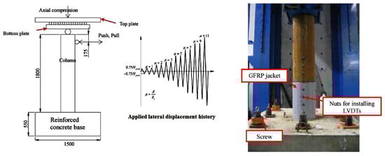
Figure 1.
Test setup (dimensions are in mm). Reprinted from Yu et al. [].
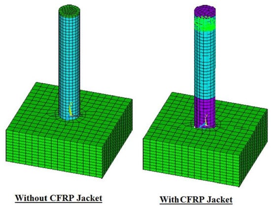
Figure 2.
Meshing of the CFT specimens with and without CFRP wrapping.
To model the concrete, SOLID65 solid element was utilized, as this element has eight nodes with the capability of translating freely in all directions, where every node has three degrees of freedom. It is worth mentioning that the SOLID65 element is distinguished for having the capabilities of cracking, crushing, and plastic deformation in three perpendicular directions. However, in this experimental work, the SOLID65 element’s capability of crushing failure has been overlooked because this type of failure was not noticed when the load was applied [,,,,,,,]. Hence, the simulated models’ tensile strains depended only on ultimate failure and emerging of cracking [,,,,,,,]. The used Poisson’s ratio for concrete ranges from 0.15 to 0.22 thus a representative value of 0.2 was selected []. To be able to identify the criterion of concrete failure, the following factors were observed: ultimate compressive strength (Figure 3), tensile strength (Figure 3), and Young’s elastic modulus []. The shear transfer coefficient (βt), which defines the crack face condition, was chosen to be 0.2, the standard value [,]. To model the FE specimens more accurately, this work adopted the model of Kent and Park [] to predict the concrete’s compressive stress and strain, as shown in Figure 3. The modelled-using-ANSYS concrete’s nonlinear stress–strain relationship is depicted in Figure 3, with a strength in compression of 36.6 MPa, strength in tension of 3.75 MPa, Poisson’s ratio of 0.20, and elastic modulus of 2250 MPa []. At this point, it is worth pointing out that SOLID65 element has the capability of representing one solid material and a maximum of three reinforcement types. In this experiment, the concrete was presumed isotropic until cracking, and then it was assumed plastic.
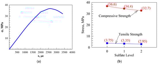
Figure 3.
Concrete: (a) stress–strain curve [] and (b) mechanical damaged subjected-to-sulfate attack. Adapted from Al-Rousan et al. [].
The smeared reinforcement approach was used to define the flexural reinforcement, as this approach is useful in defining the proper quantity of reinforcement through determining the orientation angles and mesh’s volumetric ratio. As for the steel plates and steel circular tubes, the freely translating SOLID45 element was used. As for the elastic stress–strain with linear response, it was utilized with a Young’s modulus of 203 GPa, a yield stress of 271 MPa, a Poisson’s ratio of 0.30, and an ultimate stress of 353 MPa []. Further, the SOLID46 element was utilized in the simulation of confinement with CFRP, having an elastic modulus of 237.8 GPa and an ultimate strain of 0.85%, based upon a thickness of 0.34 mm []. In addition, concrete–steel tube and CFRP–steel tube bonds were presumed to be nonslipping (i.e., perfect), as the coinciding nodes were merged. The loading process started with applying an axial load to the column. Then, horizontal load was applied increasingly, as displacement-controlled, to specify the load–displacement curve’s decreasing phase. To assure a solution that was stable and nondivergent, the loading process was performed in an incremental manner, employing a large number of substeps per every step of loading. To obtain a nonlinear solution, the Newton–Raphson equilibrium iterative method was utilized, with 1/1000 of tolerance. Calibration of the basic NLFEA modelling was achieved by using a proper mesh size, rate of loading, and considering materials’ nonlinearities.
Figure 4 reveals that the FE’s load–drift hysteresis results agree well with those obtained by Yu et al. [], who experimented with a CFT column confined with six CFRP layers (Yu et al. [] designated this column as LCFT-6C-106-F). In addition, there was a significant agreement between the study of Yu et al. [] and this study, in terms of shapes of deformation and modes of failure (Figure 5). After calibration, the FE models were employed to devise 21 FE CFT column models to evaluate the impact of the number of CFRP layers and sulfate level on the models.
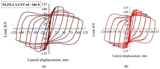
Figure 4.
Validation of the results: (a) NLFEA and (b) reprinted from Yu et al. [].
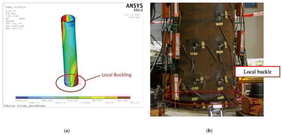
Figure 5.
Deformed shapes: (a) NLFEA and (b) result LCFT-0-106-F. Reprinted from Yu et al. [].
3. Results and Discussion
In Table 1, the results obtained from the twenty-one study specimens are summarized. The specimens were designated as follows: CFT indicates the CFT column; C X, where C indicates CFRP and X is the number of CFRP layers; and S x, where S indicates sulfate and x represents the level of attack. For example, the designation CFTC7S2 indicates a CFT circular column, confined with seven layers of CFRP and subjected to sulfate level 2. Further, results were also obtained regarding the ultimate horizontal load, the strain of reinforcing steel, net drift, the strain of CFRP, degradation of stiffness, energy dissipation, and performance enhancement factor.

Table 1.
NLFEA results of all models.
3.1. Horizontal Load–Displacement Hysteretic Loops
Each of the models was monitored for steel stress contours at each steel tube, CFRP, and core concrete. Figure 6 demonstrates the stress contours for two specimens, CFTC0S1 (i.e., unconfined with CFRP at sulfate level 1) and CFTC8S1 (i.e., confined with eight layers of CFRP, exposed to sulfate level 1), as this figure illustrates the regions with the highest stresses. Further, the CFT column model’s horizontal load–displacement hysteretic loops are demonstrated in Figure 7 (sulfate level 0), Figure 8 (sulfate level 1), and Figure 9 (sulfate level 2). The three figures indicate that the layers of CFRP played a major role in improving the behavior of CFT columns through enhancing energy dissipation, net drift capacity, and lateral load capacity. Referring to Figure 7, it is clearly revealed that the specimen CFTC0S0 (i.e., no CFRP layers and sulfate level 0) had the least horizontal load and displacement. In contrast, the column specimen that was exposed to level 1 of sulfate attack (Figure 8) and the specimen exposed to level 0 of sulfate (Figure 7) were stronger and had larger displacements than the specimen exposed to sulfate level 2, as shown in Figure 9. In addition, referring to Figure 7, Figure 8 and Figure 9, the CFRP’s horizontal load–displacement loops evidently indicate that strengthening CFT columns with CFRP significantly improved the columns’ horizontal displacement and load; the reason of this improvement was that the wraps of CFRP availed the column specimens with an external confinement mechanism when the steel tube reached buckling. Further, Figure 7, Figure 8 and Figure 9 show that the sulfate level strongly impacted the horizontal load–displacement loops; this was because the sulfate level reduced the column specimen’s compressive stress, resulting in tensile stresses in the column, which degraded its strength.
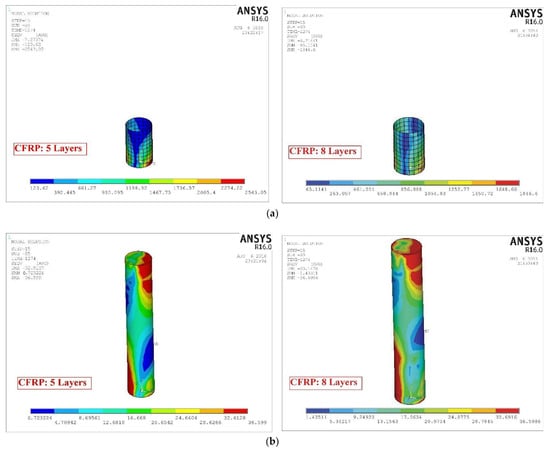
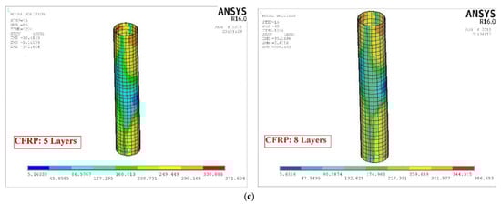
Figure 6.
Typical stress contours for sulfate level 1: (a) CFRP, (b) concrete, and (c) steel tube.
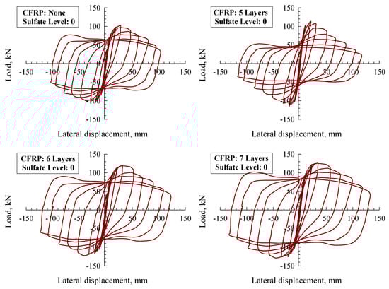
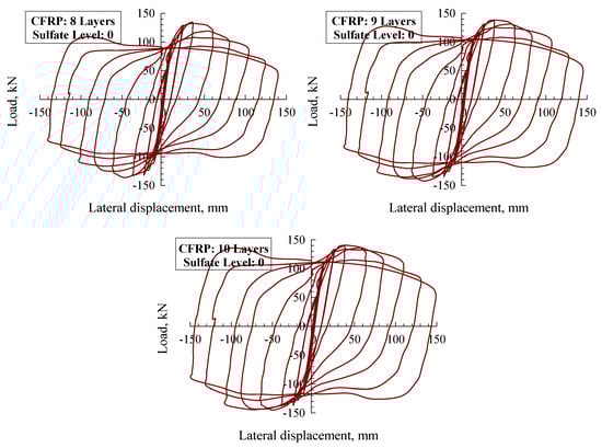
Figure 7.
CFT column horizontal load–net drift hysteresis loops for sulfate level 0.
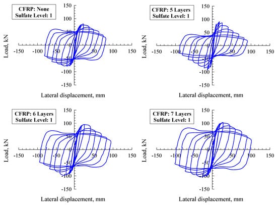
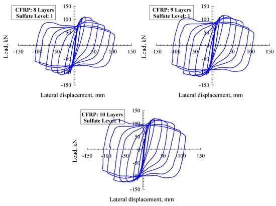
Figure 8.
CFT column horizontal load–net drift hysteresis loops for sulfate level 1.
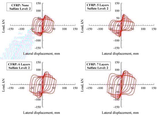
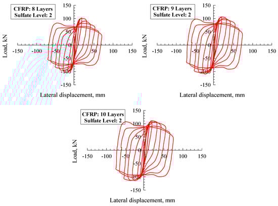
Figure 9.
CFT column horizontal load–net drift hysteresis loops for sulfate level 2.
3.2. Lateral Load and Net Drift Capacities
The values of net drift capacity and lateral load in Table 1 are normalized with respect to CFTC0S0, as shown in Figure 10 and Figure 11, respectively. Figure 10 and Figure 11 indicate the following significant findings: (1) increasing the columns’ axial load resulted in a significant disproportional increase in the lateral net drift and lessened enhancement of the lateral load capacity; (2) at a certain level of axial load, enhancing the layers of CFRP increased the lateral net drift capacity and lateral load capacity, to different extents; (3) installing less than five layers of CFRP had no considerable effect on enhancing the behavior of specimens; (4) installing eight, nine, or ten layers of CFRP had an almost similar impact when enhancing the specimens’ behavior was concerned; and (5) both the number of CFRP layers and the sulfate level significantly influenced the maximum strain of the steel tube. These findings indicate that, at level 1 of sulfate, confining CFT circular steel columns with seven layers of CFRP improved the lateral load capacity of the columns, while installing eight layers effectively enhanced the columns’ net drift. However, when specimens were exposed to sulfate level 2, the findings indicate that reinforcing CFT column specimens with a maximum of nine layers of CFRP effectively enhanced the lateral load capacity but had no influence on the net drift.
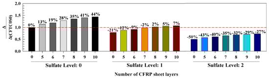
Figure 10.
Effect of investigated parameters on the maximum horizontal net drift.
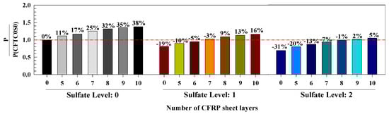
Figure 11.
Effect of the investigated parameters on the horizontal load capacity.
3.3. Horizontal Displacement–Steel Strain Responses
The data regarding the steel tube’s strains—at critical regions—are useful in investigating the behaviors of the simulated CFT column models. Figure 12 depicts the relation between the strains of the steel tube and the resultant displacement; as it is clearly indicated, the exposed-to-sulfate-level-0 CFT specimens’ steel tube strains yielded before those exposed to sulfate levels 1 and 2, as illustrated in Table 1 and Figure 12.
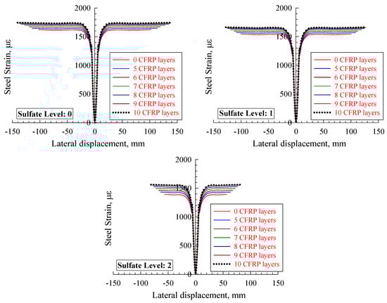
Figure 12.
Steel strain versus lateral displacement of CFT columns.
It must be noted that the strain of the reinforcing steel tube was modified as per the strain of yielding in order to highlight the influence of the study parameters on steel strain, as demonstrated in Figure 13. It is revealed from Figure 13 that, at level 0 of sulfate, the strain of the steel tube enhanced by 21%, 23%, 25%, 27%, 29%, 30%, and 30% for zero, five, six, seven, eight, nine, and ten layers, respectively, of CFRP. When exposing the specimens to sulfate level 1, the steel tube’s enhanced by 10%, 14%, 14%, 15%, 16%, 18%, and 18% when using zero, five, six, seven, eight, nine, and ten layers of CFRP, respectively. Additionally, at sulfate level 2, the results show that the steel tube’s strain increased by 1%, 4%, 6%, 8%, 10%, 12%, and 13% when using zero, five, six, seven, eight, nine, and ten layers of CFRP, respectively. The findings show that the specimens exposed to level 2 of sulfate had the least enhancement in the steel tube’s strain when the CFRP layers were increased. In addition, it has been found that the strain of the steel tube increased in a proportional manner when the number of CFRP layers was raised up to eight layers, whereas increasing the number of layers to nine or ten had no significant effect. Hence, it can be concluded that using eight CFRP layers is the most efficient at enhancing the models’ performance.
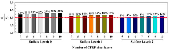
Figure 13.
Investigated parameters versus maximum steel strain.
3.4. Horizontal Displacement–CFRP Strain Responses
Figure 14 demonstrates the relation between the horizontal displacement and the CFRP strain behavior for the strengthened-with-CFRP CFT column models. The response curve has two stages: the first represents horizontal displacements from 0 to 10 mm, and the second represents displacements from 10 mm to failure. Considering Figure 14, there was a rapid increase in CFRP strain and a minimal improvement in horizontal displacement. In comparison, the rise in CFRP strain was slight with a rapid increase in horizontal displacement. In addition, Figure 15 shows that, at sulfate level 0, increasing the layers of CFRP resulted in a reduction in CFRP strain by 100% (rupture) when zero CFRP layers were used, 98% (2% reduction) at five layers, 97% (3% reduction) at six layers, 88% (12% reduction) at seven layers, 81% (19% reduction) at eight layers, and 75% (25% reduction) at nine layers. However, at sulfate level 1, the strain of CFRP reduced when the number of CFRP layers was raised, as follows: 5%, 10%, 19%, 27%, and 33% at five, six, seven, eight, nine, and ten layers, respectively. At sulfate level 2, the strain of CFRP had the most minor reduction when the number of CFRP layers was increased, as follows: 14%, 19%, 27%, 35%, and 41%, at five, six, seven, eight, nine, and ten layers, respectively. In addition, the steel tube strain was enhanced in a proportional manner when the number of CFRP layers was raised to eight to ten layers; the enhancement was barely noticed when using nine and ten layers, which indicated that eight layers of CFRP was optimal. Hence, the sulfate level reduced the CFRP strain by an average of 13% at sulfate level 0, 20% at level 1, and 28% at level 2. Lastly, using less than five layers of CFRP did not significantly improve the models’ CFRP strain.
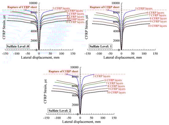
Figure 14.
CFRP strain.
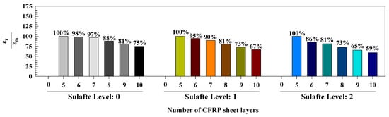
Figure 15.
CFRP strain percentages.
3.5. Stiffness Degradation
At every cycle, the stiffness was computed; the obtained values were graphically plotted to investigate the relation between the CFT column models’ stiffness and the number of cycles, as depicted in Figure 15. Inspecting Figure 16, it can be observed that there was a sharp slope in the stiffness degradation response versus the number of cycles graph when a strengthened-with-CFRP column model was used under 0% axial load. Then, upon raising the axial load, the slope became less sharp; the reason for this was that the axial load level availed the area between footing and column with excellent confinement. In addition, the results reveal that using CFRP to strengthen the CFT column barely enhanced the column’s initial stiffness and the number of cycles. Therefore, sulfate level of the column decreased initial stiffness and number of cycles as well as increased the sharpness of stiffness degradation due to the decrease in column compressive stress. Moreover, the level of sulfate reduced the degradation of stiffness by nearly 41% at sulfate level 1 and 62% at sulfate level 2 compared to that at sulfate level 0.
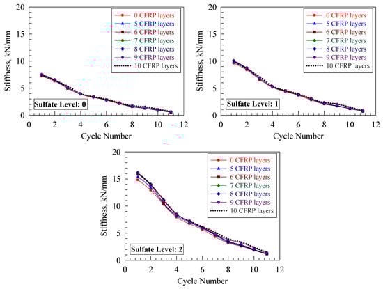
Figure 16.
Stiffness degradation.
3.6. Performance Enhancement Factor and Energy Dissipation
Table 2 demonstrates the rise in lateral load capacity and net drift represented as load and displacement factors; both were modified in accordance with the CFTC0S0 specimen (i.e., CFT column, unstrengthened, at sulfate level 0). Every model’s value of the performance factor was computed by multiplying the load factor by the displacement factor to obtain a close-to-real evaluation of the improvement, instead of relying on one aspect only. Compared with the CFTC0S0 model, the models that were exposed to sulfate level 0 had performance factors of almost 1.26, 1.39, 1.61, 1.78, 1.90, and 1.99 when using five, six, seven, eight, nine, and ten layers of CFRP, respectively. This is an indicator that in the case of using FE specimens with certain characteristics and geometric details, installing less than five layers of CFRP layers availed inconsiderable improvement.
Table 2.
Performance improvement factor and energy dissipation.
Exposing the specimens to sulfate level 1, the performance factors were almost 0.64, 0.79, 0.87, 1.00, 1.19, and 1.24 when the numbers of CFRP layers were zero, five, six, seven, eight, nine, and ten. It is noticed that the performance factors were below 1.00 when using five and six layers of CFRP, which was not considerable. Further, the models that were exposed to sulfate level 2 (compared with CFTC0S0) had performance factors of almost 0.34, 0.45, 0.52, 0.61, 0.67, 0.72, and 0.76 when the numbers of CFRP layers were zero, five, six, seven, eight, nine, and ten. As a result, all the models had performance factors below 1.00, which was not enough. It is well stipulated that the structure’s capability to dissipate energy is crucial in seismic design, as there is a proportional relationship between energy dissipation and ductility. Referring to Table 2, raising the number of CFRP layers resulted in a significant increase in energy dissipation. Contrarily, raising the sulfate level resulted in a decrease in energy dissipation. The results show that the normalized values of energy dissipation agreed, to an extent, with the performance enhancement factor, which was reasonable since both the strengths and displacements were given the same weight upon computing the performance factors. It is necessary to state that it is possible to compute the performance enhancement factor for several applications by assigning different weights to strength and ductility. In other words, when considering strength, the strength may be given 0.75% of weight while ductility may be 0.25%, or the other way around.
4. Conclusions
Twenty-one adequately calibrated FE models were devised and soundly verified in accordance with credible experimental results to investigate the impact of the number of CFRP layers and the sulfate level on the behavior of CFT circular steel columns. Based on the study results, the following conclusions are reached:
- The enhancement in performance depends, disproportionally, on the properties of the CFT steel column, sulfate level, and the number of CFRP wraps. Adequate FE modelling is imperative to strengthen CFT circular steel columns properly.
- Confining CFT column models with five to ten CFRP layers increases the lateral load capacity, drift capacity, performance factor, and energy dissipation.
- Confining CFT circular steel columns with CFRP layers improves the lateral structural performance.
- Using eight layers of CFRP to confine CFT column models effectively improves the models’ performance, unlike using nine and ten layers of CFRP, which has no significant impact. In other words, eight CFRP layers is the best configuration to provide optimum results.
- The study outcomes could be a helpful guideline and an excellent methodology for reinforcing CFT steel columns.
Author Contributions
Conceptualization, R.A.-R. and N.D.L.; methodology, R.A.-R. and K.A.; formal analysis, R.A.-R. and N.D.L.; investigation, R.A.-R. and O.N.; resources, R.A.-R. and K.A.; data curation, R.A.-R. and K.A.; writing—original draft preparation, R.A.-R. and O.N.; writing—review and editing, M.A., R.A.-R. and K.A.; visualization, R.A.-R. and O.N.; supervision, R.A.-R.; project administration, R.A.-R.; funding acquisition, R.A.-R. All authors have read and agreed to the published version of the manuscript.
Funding
This research was funded by European Union funds, grant number 101007595.
Institutional Review Board Statement
Not applicable.
Informed Consent Statement
Not applicable.
Data Availability Statement
Not applicable.
Acknowledgments
Part of this research was supported by the ADDOPTML (ADDitively Manufactured OPTimized Structures by means of Machine Learning) project (No: 101007595) belonging to the Marie Skłodowska-Curie Actions (MSCA) Research and Innovation Staff Exchange (RISE) H2020-MSCA-RISE-2020. Their support is highly acknowledged. The authors would also like to thank the Jordan University of Science and Technology for its support.
Conflicts of Interest
The authors declare no conflict of interest.
References
- Xue, J.-Q.; Fiore, A.; Liu, Z.-H.; Briseghella, B.; Marano, G.C. Prediction of Ultimate Load Capacities of CFST Columns with Debonding by EPR. Thin-Walled Struct. 2021, 164, 1079121. [Google Scholar] [CrossRef]
- Zhou, F.; Xu, W. Cyclic loading tests on concrete-filled double-skin (SHS outer and CHS inner) stainless steel tubular beam-columns. Eng. Struct. 2016, 127, 304–318. [Google Scholar] [CrossRef]
- Feng, R.; Chen, Y.; Wei, J.; Huang, J.; Huang, J.; He, K. Experimental and numerical investigations on flexural behaviour of CFRP reinforced concrete-filled stainless steel CHS tubes. Eng. Struct. 2018, 156, 305–321. [Google Scholar] [CrossRef]
- Xiao, Y. Applications of FRP Composites in Concrete Columns. Adv. Struct. Eng. 2004, 7, 335–343. [Google Scholar] [CrossRef]
- Teng, J.; Yu, T.; Fernando, D. Strengthening of steel structures with fiber-reinforced polymer composites. J. Constr. Steel Res. 2012, 78, 131–143. [Google Scholar] [CrossRef]
- Mao, X.; Xiao, Y. Seismic behavior of confined square CFT columns. Eng. Struct. 2006, 28, 1378–1386. [Google Scholar] [CrossRef]
- He, A.; Su, A.; Liang, Y.; Zhao, O. Experimental and numerical investigations of circular recycled aggregate concrete-filled stainless steel tube columns. J. Constr. Steel Res. 2021, 179, 106566. [Google Scholar] [CrossRef]
- Qin, P.; Xiao, Y.; Zhou, Y.; Zhang, G. Research on CFRP confined circular concrete-filled steel tubular columns subjected to cyclic lateral forces. J. Earthq. Eng. Eng. Vib. 2013, 33, 190–196. [Google Scholar]
- Zheng, Y.; He, C.; Zheng, L. Experimental and numerical investigation of circular double-tube concrete-filled stainless steel tubular columns under cyclic loading. Thin-Walled Struct. 2018, 132, 151–166. [Google Scholar] [CrossRef]
- Wang, Z.-B.; Zhang, J.-B.; Li, W.; Wu, H.-J. Seismic performance of stiffened concrete-filled double skin steel tubes. J. Constr. Steel Res. 2020, 169, 106020. [Google Scholar] [CrossRef]
- Li, W.; Wang, T.; Han, L.-H. Seismic performance of concrete-filled double-skin steel tubes after exposure to fire: Experiments. J. Constr. Steel Res. 2018, 154, 209–223. [Google Scholar] [CrossRef]
- Liu, L.; Lu, Y. Axial bearing capacity of short FRP confined concrete-filled steel tubular columns. J. Wuhan Univ. Technol. Sci. Ed. 2010, 25, 454–458. [Google Scholar] [CrossRef]
- Park, J.W.; Hong, Y.K.; Choi, S.M. Behaviors of concrete filled square steel tubes confined by carbon fiber sheets (CFS) under compression and cyclic loads. Steel Compos. Struct. 2010, 10, 187–205. [Google Scholar] [CrossRef]
- Abdalla, S.; Abed, F.; Alhamaydeh, M. Behaviour of CFSTs and CCFSTs under quasi- static axial compression. J. Constr. Steel Res. 2013, 90, 235–244. [Google Scholar] [CrossRef]
- Wang, Z.-B.; Yu, Q.; Tao, Z. Behaviour of CFRP externally-reinforced circular CFST members under combined tension and bending. J. Constr. Steel Res. 2014, 106, 122–137. [Google Scholar] [CrossRef]
- Hu, Y.M.; Yu, T.; Teng, J.G. FRP-Confined Circular Concrete-Filled Thin Steel Tubes under Axial Compression. J. Compos. Constr. 2011, 15, 850–860. [Google Scholar] [CrossRef]
- Yu, T.; Hu, Y.; Teng, J. FRP-confined circular concrete-filled steel tubular columns under cyclic axial compression. J. Constr. Steel Res. 2014, 94, 33–48. [Google Scholar] [CrossRef]
- Teng, J.G.; Hu, Y.M.; Yu, T. Stress-strain model for concrete in FRP-confined steel tubular columns. Eng. Struct. 2013, 49, 156–167. [Google Scholar] [CrossRef]
- Monteiroa, P.J.M.; Kurtis, K.E. Time to failure for concrete exposed to severe sulfate attack. Cem. Concr. Res. 2003, 33, 987–993. [Google Scholar] [CrossRef]
- Hekal, E.; Kishar, E.; Mostafa, H. Magnesium sulfate attack on hardened blended cement pastes under different circumstances. Cem. Concr. Res. 2002, 32, 1421–1427. [Google Scholar] [CrossRef]
- Al-Dulaijan, S.; Maslehuddin, M.; Al-Zahrani, M.; Sharif, A.; Shameem, M.; Ibrahim, M. Sulfate resistance of plain and blended cements exposed to varying concentrations of sodium sulfate. Cem. Concr. Compos. 2003, 25, 429–437. [Google Scholar] [CrossRef]
- Lee, S.; Moon, H.; Hooton, R.D.; Kim, J. Effect of solution concentrations and replacement levels of metakaolin on the resistance of mortars exposed to magnesium sulfate solutions. Cem. Concr. Res. 2005, 35, 1314–1323. [Google Scholar] [CrossRef]
- Al-Rousan, R.Z.; Sharma, A. Integration of FRP sheet as internal reinforcement in reinforced concrete beam-column joints exposed to sulfate damaged. Structures 2021, 31, 891–908. [Google Scholar] [CrossRef]
- Al-Rousan, R.Z.; Alkhawaldeh, A. Behavior of heated damaged reinforced concrete beam-column joints strengthened with FRP. Case Stud. Constr. Mater. 2021, 15, e00584. [Google Scholar] [CrossRef]
- Al-Rousan, R.Z.; Alkhawaldeh, A. Numerical simulation of the influence of bond strength degradation on the behavior of reinforced concrete beam-column joints externally strengthened with FRP sheets. Case Stud. Constr. Mater. 2021, 15, e00567. [Google Scholar] [CrossRef]
- Venkatesan, B.; Ilangovan, R.; Jayabalan, P.; Mahendran, N.; Sakthieswaran, N. Finite element analysis (FEA) for the beam-column joint subjected to cyclic loading was performed using ANSYS. Circuits Syst. 2016, 7, 1581–1597. [Google Scholar] [CrossRef] [Green Version]
- Al-Rousan, R.Z.; Alhassan, M.A.; Al-Omary, R.J. Response of interior beam-column connections integrated with various schemes of CFRP composites. Case Stud. Constr. Mater. 2021, 14, e00488. [Google Scholar] [CrossRef]
- Alhassan, M.; Al-Rousan, R.Z.; Amaireh, L.K.; Barfed, M.H. Nonlinear Finite Element Analysis of B-C Connections: Influence of the Column Axial Load, Jacket Thickness, and Fiber Dosage. Structures 2018, 16, 50–62. [Google Scholar] [CrossRef]
- Abdalla, K.M.; Alhassan, M.A.; Al-Rousan, R.; Lagaros, N.D. Finite-element modelling of concrete-filled steel tube columns wrapped with CFRP. Proc. Inst. Civ. Eng. Struct. Build. 2020, 173, 844–857. [Google Scholar] [CrossRef]
- Shaaban, I.G.; Said, M. Finite element modeling of exterior beam-column joints strengthened by ferrocement under cyclic loading. Case Stud. Constr. Mater. 2018, 8, 333–346. [Google Scholar] [CrossRef]
- Al-Rousan, R.; Haddad, R.; Al-Sa’di, K. Effect of Sulfates on bond behavior between carbon fiber reinforced polymer sheets and concrete. Mater. Des. J. 2013, 43, 237–248. [Google Scholar] [CrossRef]
- Yu, T.; Hu, Y.; Teng, J. Cyclic lateral response of FRP-confined circular concrete-filled steel tubular columns. J. Constr. Steel Res. 2016, 124, 12–22. [Google Scholar] [CrossRef] [Green Version]
- ANSYS. ANSYS User’s Manual Revision 16.0; ANSYS, Inc.: Canonsburg, PA, USA; Available online: https://dokumen.tips/spiritual/ansys-16-manual-pdf.html (accessed on 8 February 2022).
- ASCE Task Committee on Concrete and Masonry Structure. State of the Art Report on Finite Element Analysis of Reinforced Concrete; ASCE: Reston, VA, USA, 1982. [Google Scholar]
- ACI Committee 318. Building Code Requirements for Structural Concrete (ACI 318–014) and Commentary (ACI 318R–14); American Concrete Institute: Farmington Hills, MI, USA, 2014. [Google Scholar]
- Hemmaty, Y. Modeling of the shear force transferred between cracks in reinforced and fiber reinforced concrete structures. Proc. ANSYS Conf. 1998, 1, 1–13. [Google Scholar]
- Huyse, L.; Hemmaty, Y.; Vandewalle, L. Finite element modeling of fiber reinforced concrete beams. In Proceedings of the ANSYS Conference, Pittsburgh, PA, USA, 2–6 May 1994. [Google Scholar]
- Kent, D.C.; Park, R. Flexural members with confined concrete. J. Struct. Div. 1971, 97, 1969–1990. [Google Scholar] [CrossRef]
Publisher’s Note: MDPI stays neutral with regard to jurisdictional claims in published maps and institutional affiliations. |
© 2022 by the authors. Licensee MDPI, Basel, Switzerland. This article is an open access article distributed under the terms and conditions of the Creative Commons Attribution (CC BY) license (https://creativecommons.org/licenses/by/4.0/).