Article

Web Crippling Behaviour of Cold-Formed High Strength Steel Unlipped Channel Beams

by
Elilarasi Kanthasamy
1,
Husam Alsanat
2,
Keerthan Poologanathan
1,
Perampalam Gatheeshgar
1,3,*,
Marco Corradi
1,4,
Kajaharan Thirunavukkarasu
5 and
Madhushan Dissanayake
1
1
Department of Mechanical and Construction Engineering, Northumbria University, Newcastle upon Tyne NE1 8ST, UK
2
Department of Civil Engineering, School of Engineering, Al-Hussein Bin Talal (AHU) University, Ma’an P.O. Box 20, Jordan
3
School of Computing, Engineering, and Digital Technologies, Teesside University, Middlesbrough TS1 3BX, UK
4
Department of Engineering, Perugia University, 06125 Perugia, Italy
5
Institute of Technology, University of Moratuwa, Homagama 10200, Sri Lanka
*
Author to whom correspondence should be addressed.
Buildings 2022, 12(3), 291; https://doi.org/10.3390/buildings12030291
Submission received: 24 January 2022 / Revised: 19 February 2022 / Accepted: 21 February 2022 / Published: 2 March 2022
(This article belongs to the Special Issue Structural Performance of Cold-Formed Steel Structures)

Abstract

:
Cold-formed sections (CFS) fabricated using high strength steel have recently been utilised in construction due to their numerous advantages, such as higher load-to-weight ratio, flexibility of shape, and availability in relatively long spans. High strength CFS channel sections can be used as purlins and joists in structural systems; thus, they are vulnerable to different buckling instabilities, including web crippling. Predicting their web crippling capacity using the current design guidelines may be insufficient due to their empirical nature. This study, therefore, aims to investigate the web crippling capacity of high strength unlipped CFS sections under End-Two-Flange (ETF) loading conditions. Numerical simulations were carried out using nonlinear finite element (FE) analysis. The developed models were first validated against available experimental data and then used as a base for conducting an extensive parametric study. The ultimate web crippling capacity obtained from the parametric study was used to assess the accuracy of the available design equations in the standards and those proposed in the relevant studies. The assessment revealed that the existing design equations are not suitable for predicting the ultimate web crippling capacity for high strength CFS channel sections under the ETF loading condition. Thus, a modified design equation was proposed, following the same technique of current design standards, and a new Direct Strength Method (DSM) approach was developed.

1. Introduction

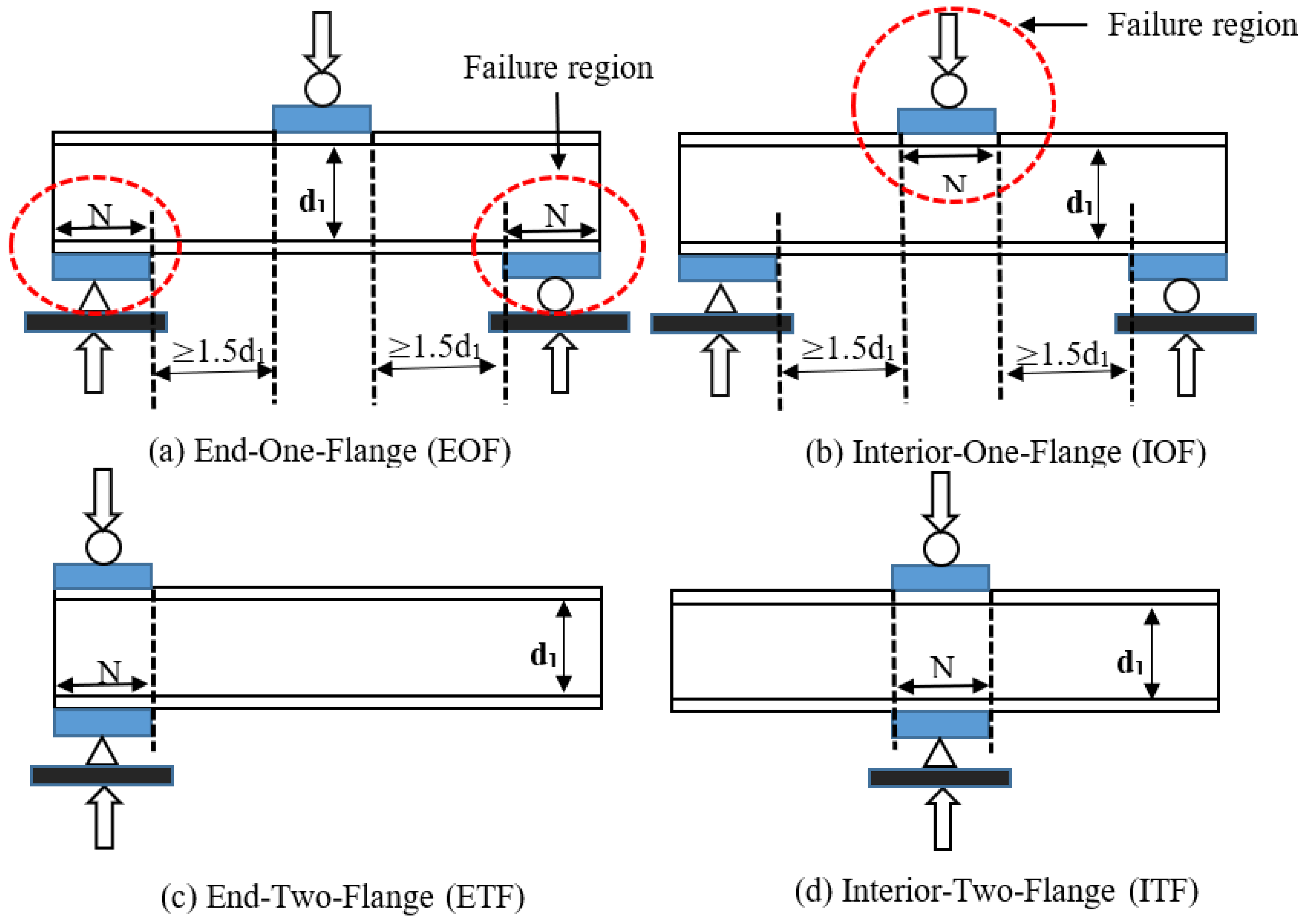
Cold-formed steel members have been extensively used in structural frame systems due to their prominent advantages, including light weight, durability, stability, high accuracy in fabrication, efficient erection, high strength-to-weight ratio and high stiffness. Different shapes of CFS sections, such as LiteSteel Beam (LSB) and built-up sections, as well as conventional sections (Z-section, C-section, ∑-section and track sections), have been developed to meet construction needs [1]. High strength steel is one of the great additions to the construction industry; it is capable of fulfilling structural design needs such as longer spans, higher strength with reduced construction mass, higher load-carrying capacity and reduced self-weight in high-rise buildings [2]. The structural performance of high strength steel sections has been studied by various researchers [2,3,4,5]. Web crippling is a vulnerability of CFS members under concentrated reactions and concentrated transverse reactions due to their thin cross sections. Since the 1940s, several experimental investigations of the web crippling behaviour of cold-formed steel sections [6,7,8,9,10,11] have been conducted by researchers, and web crippling design equations and standards have been adopted in design specifications such as Eurocode 3 Part 1–3 [12], AISI S100 [13] and AS/NZS 4600 [14]. In addition, the design specifications assign the failure modes of web crippling to four categories—Interior-Two-Flange (ITF), End-Two-Flange (ETF), End-One-Flange (EOF) and Interior-One-Flange (IOF)—according to the locations of the loading, supporting and failure region [13]. The web crippling load cases are illustrated in Figure 1.
The web crippling behaviour of CFS channel sections under all four load cases, considering different supporting conditions (fastened support to the flanges or unfastened support to the flanges), has been investigated, and improvements in the codified design equations have been proposed [15,16,17,18,19,20,21,22,23,24,25,26,27,28,29,30,31,32,33,34,35]. Moreover, web crippling studies have been conducted on various sections, such as rectangular hollow flange sections [36,37,38,39] and SupaCee sections [17,40], to check the applicability of the codified design equations available in the standards, whilst some studies have investigated the web crippling behaviour of various sections with web openings [41,42,43,44,45]. However, all these findings are limited to a yield strength less than 500 MPa, due to the unavailability of cold-forming technology [5]. High strength steel sections are receiving attention from the construction community due to their added benefits in terms of structural and architectural behaviour [5]. The researchers Santaputra et al. [3] and Wu et al. [4] studied the web crippling of high strength steel, including brake-pressed hat and built-up sections and hat and deck sections, respectively. The study of Santaputra et al. [3] covered a steel section strength of 401 to 1138 MPa, whilst Wu et al. [4] considered the virgin material yield stresses parallel to the rolling directions, ranging from 716 to 776 MPa, and perpendicular to the rolling directions, ranging from 825 to 894 MPa. Furthermore, web crippling investigation on high strength tubular sections (square and rectangular) under all four load cases was carried out by Li and Young [2,5]. The researchers considered the yield strengths of 700 MPa and 900 MPa in their study [2,5]. Sundarajah et al. [18] investigated the web crippling behaviour of high strength steel lipped channel sections under EOF and IOF loading conditions. The study also limited the investigation to less than 550 MPa.
This paper investigates the web crippling behaviour of unlipped channel sections under the ETF load case, with high strength material (yield strength of 700 MPa, 900 MPa and 1000 MPa). In total, 243 numerical studies, following the validation study, were conducted to investigate the web crippling behaviour and evaluate the applicability of current design equations available in standards. The test specimen length and loading conditions were chosen as denoted in the design specifications [12,13,14]. Web crippling strengths for this study were compared to the predictions of codified design equations provided in the design standards [12,13,14] and with previous studies on cold-formed unlipped channel sections [21,22]. Finally, this paper proposes a modified design equation for the web crippling capacity of CFS lipped channel sections with high strength under the ETF load case based on the current design standards. A DSM design equation was also proposed for this study.

2. Finite Element Modelling Description

The web crippling behaviour of channel sections can be predicted using Finite Element (FE) software and using experimental studies available in the literature [17,19,20,21,22,23,24,25,26,27,36,40]. The experimental set-up of channel sections as shown in Figure 2 is simulated using ABAQUS version 6.14 (developed by Dassault Systèmes Simulia Corp., Johnston, RI, USA) [46] to extend the study of the web crippling of unlipped channel sections with high strength material. In this study, full and then half models with axial symmetry assignment along the symmetrical line were analysed during the validation (Figure 3). Similar behaviours in both models were obtained and are discussed in Section 3 in detail. The number of elements and Degree of Freedoms (DoFs) for the half models are less than that of the full model, and thus reduced analysis time was observed for the half model as compared to the full model. In addition, a simplified modelling process was addressed during the half model development. Hence, the half model set-up was adopted during the parametric studies and is described herein.

2.1. Element Type and Mesh

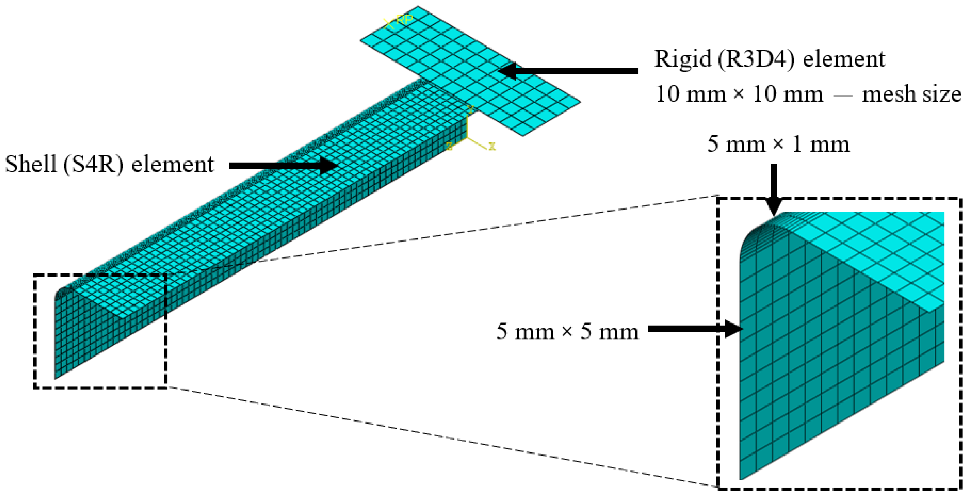
The FE model was developed with two major parts: the cold-formed channel beams and bearing plate. The 3D deformable shell element type of S4R was assigned to the cold-formed steel beam, whilst rigid element R3D4 was used to create the bearing plates. Although various types of elements are available in the ABAQUS, the above-mentioned element types were chosen according to the various previous numerical studies conducted on web crippling [2,16,17,19,25,26,27]. Since the shell offset definition was set to be the middle surface, the centre-line dimensions were simulated in accordance with the ABAQUS. This means the middle surface would act as a reference surface, and an assigned thickness will be added to both sides of the reference surface with half of the thickness [46]. Mesh size is rather crucial factor in deciding the accuracy of numerical results. Mesh size of the cold-formed steel beam was adopted in this study as indicated in the previous web crippling studies based on mesh refinement analysis [16,17,18,19]. In this study, the mesh size of the flat region and corner regions was 5 mm × 5 mm and 5 mm × 1 mm, respectively. The applied mesh sizes and element types are shown in Figure 4. Plastic deformation at the web-flange juncture and appropriate load transfer to the web from the flange is significantly influenced by the corner region, and thus finer mesh is recommended for the corner radii in the web crippling studies [16,17,18,19]. Since the rigid plate does not take part in the finite element analyses, the mesh size of the bearing plate was assigned as 10 mm × 10 mm.

2.2. Material Modelling

The two-stage Ramberg–Osgood model is used to describe the stress–strain behaviour of the stainless steels and cold-formed steels. Even though a number of researchers have investigated the behaviour of stainless steel [47,48,49,50,51], only a few researchers have studied the material modelling of cold-formed steel [52,53]. Recently, Leroy Gardner and Xiang Yun [54] proposed a two-stage Ramberg–Osgood model (Equations (1)–(6)) to describe the stress–strain curve of the cold-formed steel, which is based upon the material model developed by Mirambell and Real [51] for stainless steel. The researchers [54] gathered many stress–strain models from a literature review by considering various material strengths, shapes and forms of production, such as press-braked or cold-rolled and validated. In addition, the study [54] suggested that the study of Rossi et al. [55] can be used to obtain the material model of the corner regions (Equations (7)–(10)). The material models proposed by Gardner and Yun [54] and Rossi et al. [55] were applied in this study to determine the stress–strain behaviour of the flat and corner regions, respectively.
The applied stress–strain relationship of the flat region in this study is as follows:
ε = { f E + 0.002 ( f f y ) n f f y E 0.2 + ( ε u ε 0.2 f u f y E 0.2 ) ( f f y f u f y ) m + ε 0.2
The suggested values and expressions for the key input parameters in Equation (1) are as follows:
n—First strain-hardening exponent:
n = ln ( 4 ) ln ( f y / σ 0.05 )
In this study, the first strain-hardening exponent was taken from following table (Table 1) [55].
E0.2—Tangent modulus of the stress–strain curve at the yield strength (0.2% proof stress):
E 0.2 = E 1 + 0.002 n E f y
εu —Strain corresponding to the ultimate tensile strength fu:
ε u = 0.6 ( 1 f y f u )
For an unknown ultimate strength, fu:
f u f y = 1 + ( 130 f y ) 1.4
m—Second strain-hardening exponent:
m = 1 + 3.3 f y f u
fy,c—Enhanced yield strength of corner regions of cold-rolled or press-braked sections:
f y , c = p ( ε c , a v + ε 0.2 ) q , b u t f u
εc,av—Average plastic strain induced during the forming of the corner regions of press-braked and cold-rolled sections:
ε c , a v = t 2 ( 2 r i + t )
p and q—Material parameters calculated directly from the basic properties of the unformed material:
p = f y ε 0.2 q
q = ln ( f y f u ) ln ( ε 0.2 ε u )
Figure 5 shows the applied material stress–strain curve of the flat and corner regions for a yield strength of 700 MPa. The derived engineering stress–strain curve is then converted to a true stress–strain curve, as stated in the ABAQUS [46]. Then, a weight density of 7850 kg/m3, Young’s modulus of 203,000 MPa and Poisson’s ratio of 0.3 were applied as the material properties.

2.3. Loading and Boundary Conditions

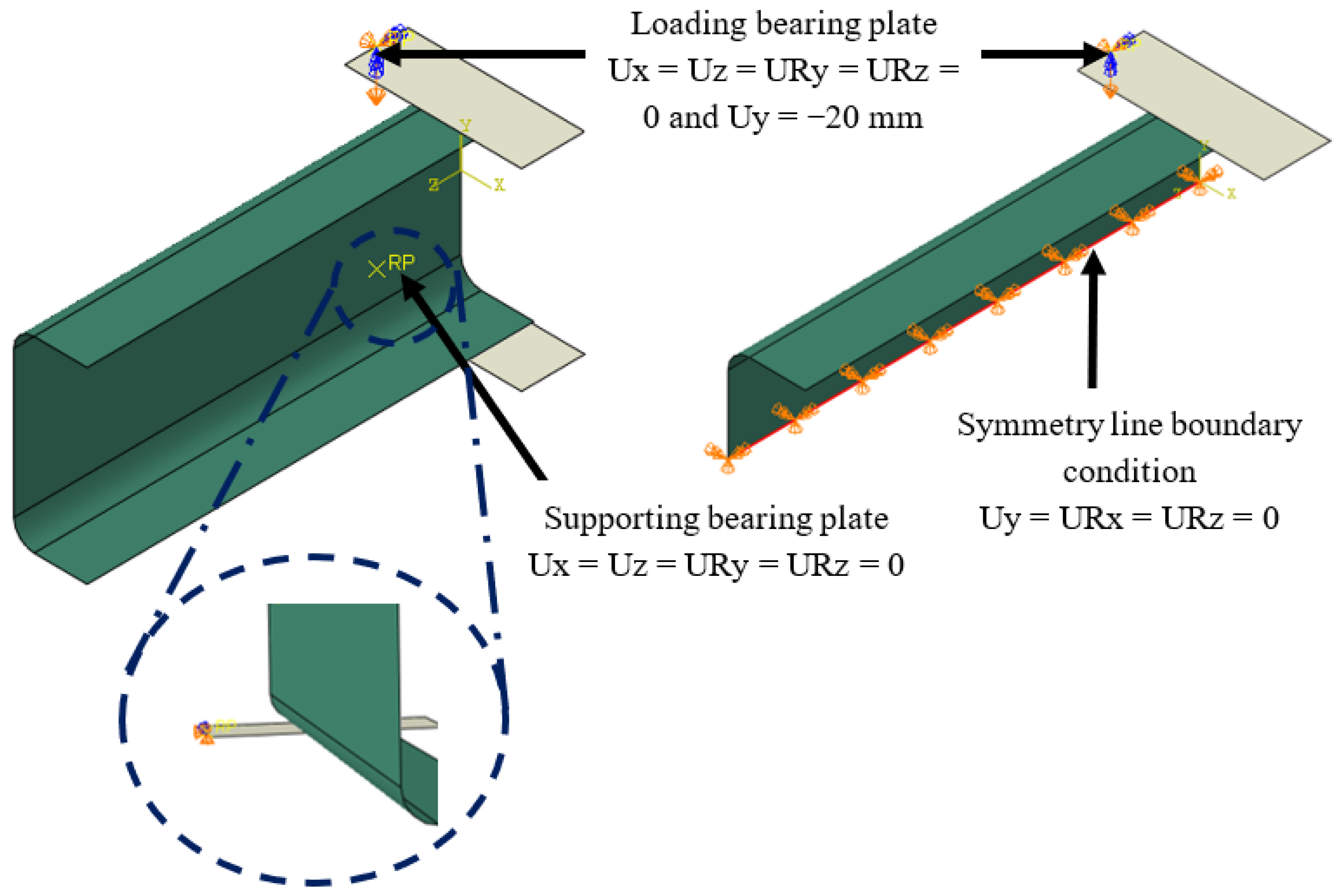
Since full and half models were developed during the validation, different boundary conditions were applied to the two models, as shown in Figure 6. The boundary conditions respective of loading and supporting were applied to the bearing plate via a reference point on the plates, whilst boundary conditions were employed for the symmetry line of the channel section to replicate the symmetrical type used for the cold-formed steel beam in the half models. Translation of the loading plate along the X-axis and Z-axis and rotation about the Y-axis and Z-axis were restrained, whilst a −20 mm displacement was applied in the vertical direction to simulate the experimental set-up of web crippling studies. The supporting plate in the full model was restrained with all movements, except rotation about the X-axis. As half hinges are used in the experimental set-up, loading and supporting plates are allowed to rotate about the X-axis. Vertical displacement at the loading plate was controlled using an amplitude model of smooth step, which ensures the smooth deformation from the initial stage. Various types of boundary conditions are available in the ABAQUS, and the symmetrical (symmetry/antisymmetry/encastre) type of boundary condition was applied along the symmetrical line of the cold-formed beam. The translation along the Y-axis and rotation about the X-axis and Z-axis were restrained along the symmetrical line. Previous studies also used similar boundary conditions for web crippling studies [2,16,17,19,25,26,27,31,36,37,38].

2.4. Contact Formulation and Properties

Interactions between bearing plates and the cold-formed steel beam were assigned by generating the surface-to-surface contacts with contact properties. Even though contact formulation can be described using various methods, such as general contact, contact pair and surface-to-surface contact, the surface-to-surface contact method was employed in this study in accordance with previous research [2,17,19,26,27]. Rigid bearing plates were defined as master surfaces, whereas the flange of the beam and corner radii were specified as slave surfaces during the contact formulation. Normal and tangential behaviours were also assigned in the contact formulation. For the contact properties, a pressure overclosure of “hard” contact in the normal direction and a friction formulation of a penalty with a 0.4 friction coefficient were employed [21,25,36].

2.5. Analysis Method

ABAQUS/Implicit and ABAQUS/Explicit are capable of solving the static and quasi-static problems in the ABAQUS [46]. However, due to the convergence issues that occurred during the application of the ABAQUS/Implicit analysis method, ABAQUS/Explicit was employed in this study to simulate the web crippling behaviour of the channel section. Previous studies also investigated the application of various analysis methods and revealed that the explicit method requires a huge number of increments; thus, the method can be more efficient and is more suitable for complex nonlinear problems as well as convergence issues generated by the other solver options [19].

2.6. Initial Geometric Imperfections

The effect of initial geometric imperfection has been neglected in various research studies, since it does not greatly affect the ultimate web crippling capacity [19,26]. Therefore, the effect of geometrical imperfection was not considered in this study.

2.7. Residual Stresses

Residual stresses can be categorized into flexural/bending and membrane residual stresses. However, previous studies have stated that the effects of membrane and flexural residual stresses on the web crippling capacity are less than 0.5% [25]; therefore, the residual stress effect was not considered in this study.

3. Validation of Numerical Models

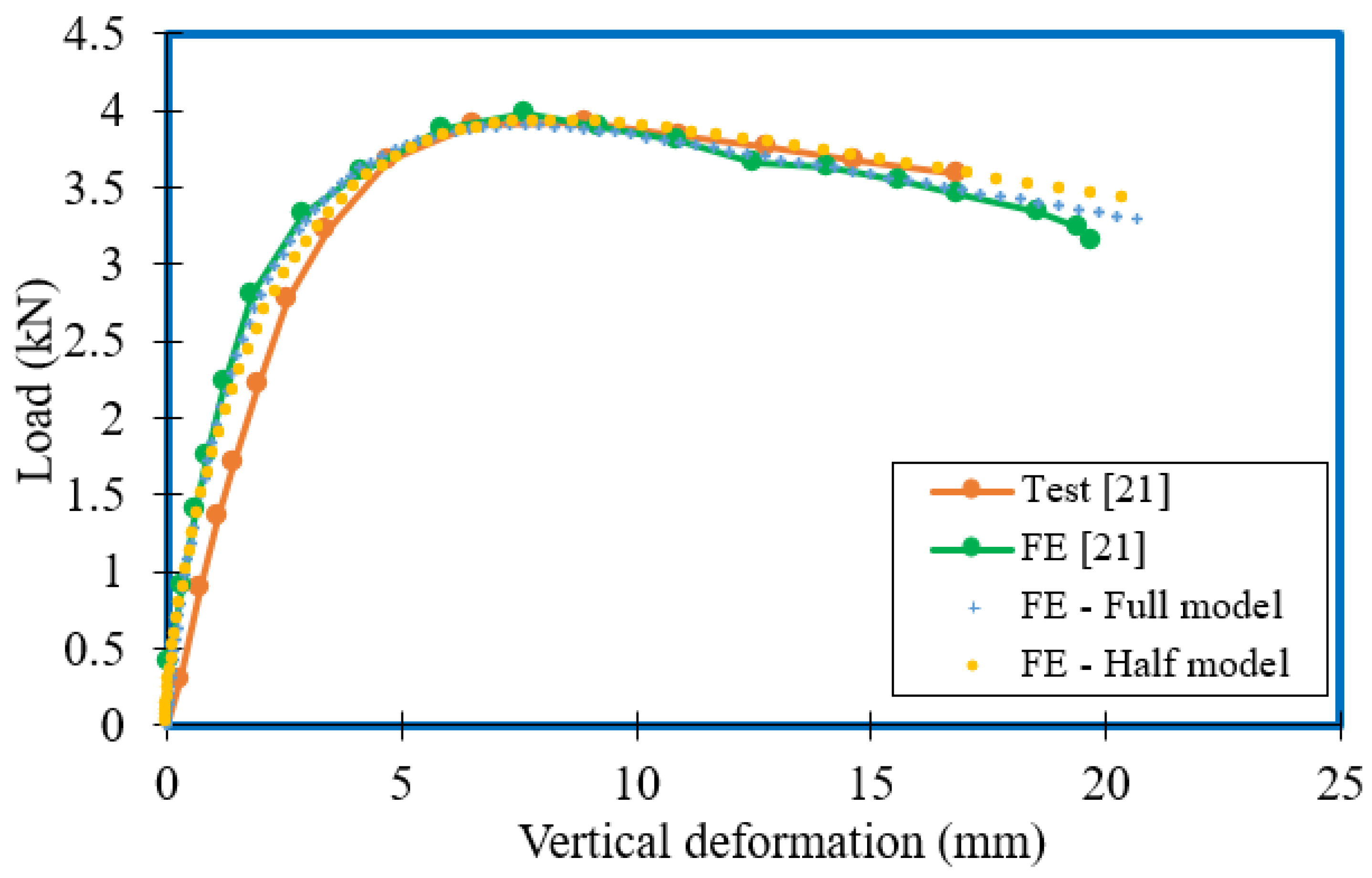
Web crippling experimental studies on tubular sections with high strength cold-formed steel [2,5] and unlipped channel sections with yield strengths of 500 MPa to 600 MPa [21] under ETF loading conditions were validated in this study to ensure the accuracy of the numerical model. The developed FE models were verified by comparing the (i) web crippling failure loads, (ii) failure modes and (iii) applied load vs. vertical deflection curves with corresponding experimental results [2,5,21]. Since half models were used in this study during the parametric studies, both the full and half models generated and validated are presented here. A good agreement was obtained for the models, and less analysis time was required for the half models compared to the full models. Thus, the authors used the half models during the parametric studies.
A comparison based on the web crippling failure load (ultimate load) of the ten experimental studies was carried out for both the full and half models and is presented in Table 2 and Table 3 for tubular sections and unlipped channel sections, respectively. The validation was conducted for a material strength of 700 MPa and 900 MPa for tubular sections, whilst for unlipped channel sections, a strength of 500 MPa to 600 MPa was used. The mean and COV values for the ratio between the experimental and FE results were also observed, as shown in Table 2 and Table 3. The mean value and COV of tubular sections with high strength material for the full model were 0.94 and 0.05, and for the half model they were 0.95 and 0.05, respectively. Meanwhile the mean and COV of unlipped channel sections for full models were 1.00 and 0.02, and for half models they were 1.00 and 0.03. A summary of the validation results is given in Table 4. The comparison indicated that developed FE models were capable of predicting well the experimental study, with less than 10% deviation under the ETF loading condition in terms of failure load.
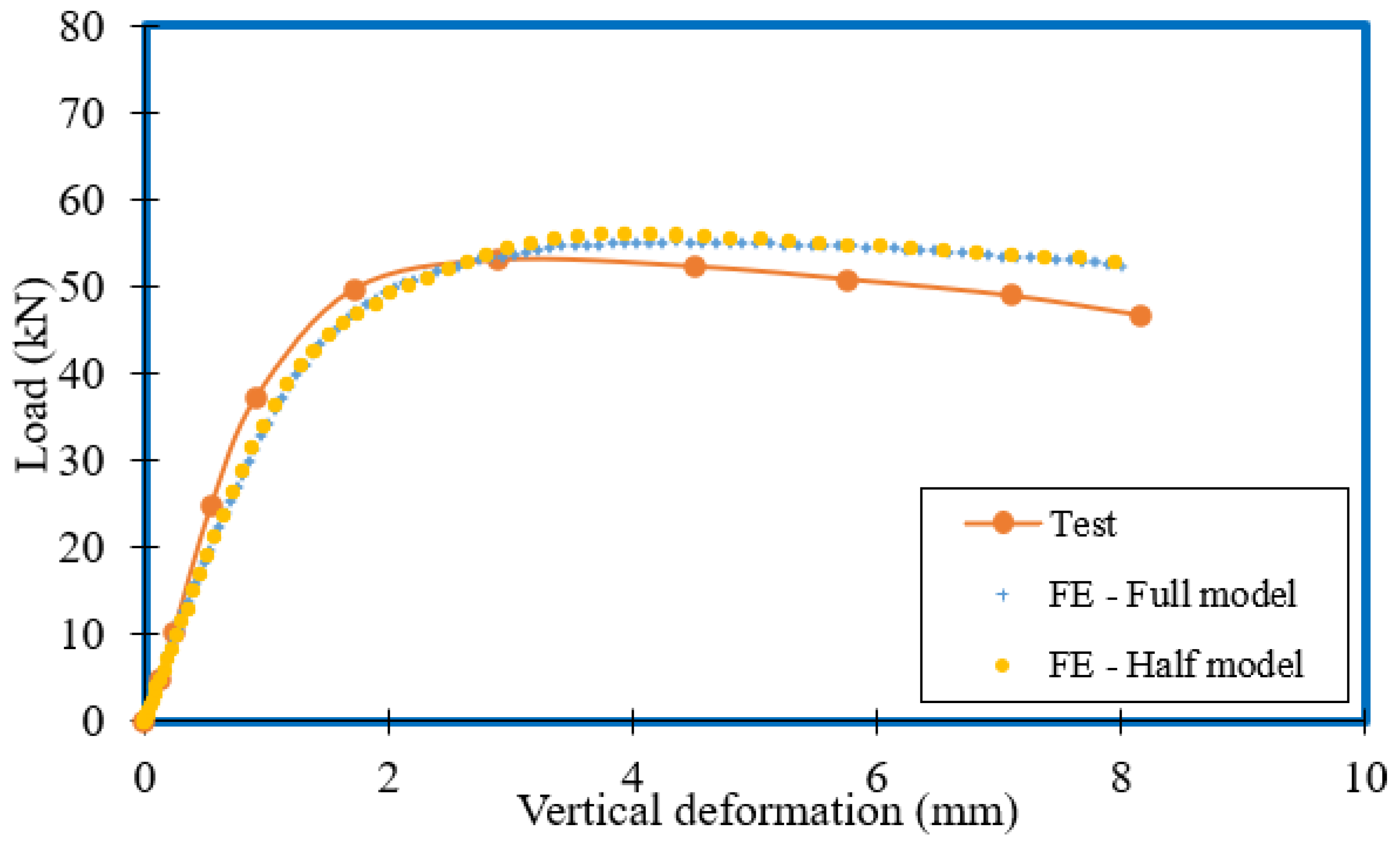
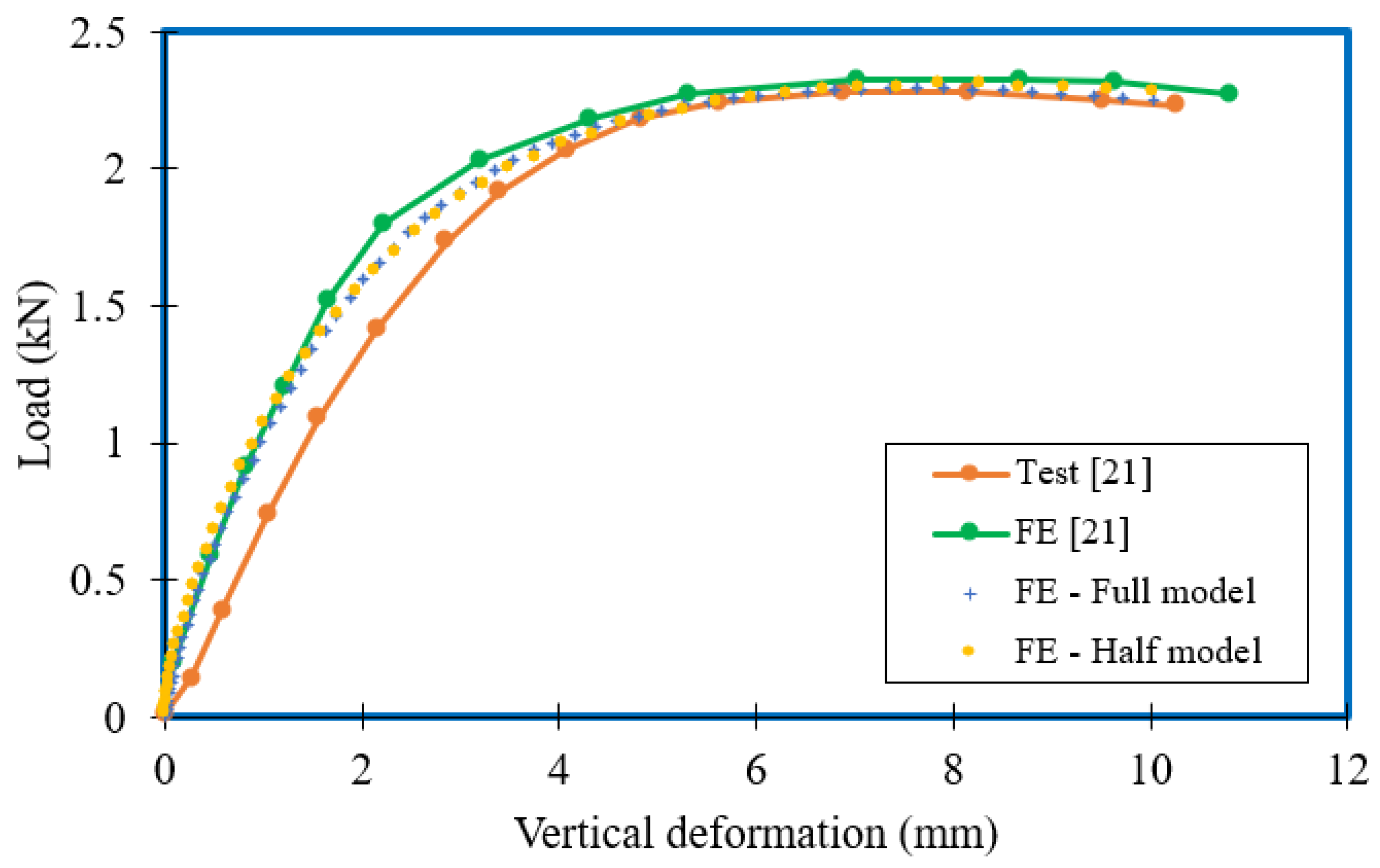
The numerical models were validated based on the load vs. vertical deformation curve for both tubular and unlipped channel sections [2,21]. The load vs. vertical deformation curve for tubular section ETF H120X120X4 with a bearing plate length of 60 mm was plotted against the load–vertical deformation curve of numerical models, whilst three experimental studies of unlipped channel sections, including ETF-UC10012 with 50 mm bearing length, ETF-UC15015 with 100 mm bearing length and ETF-UC20015 with 150 mm bearing length, were compared for unlipped channel sections. The curves were also compared for both the full and half models to ensure the usage of half models in the parametric study. The obtained plots are shown in Figure 7, Figure 8, Figure 9 and Figure 10; FE models represented the experimental load–vertical deformation curve well.
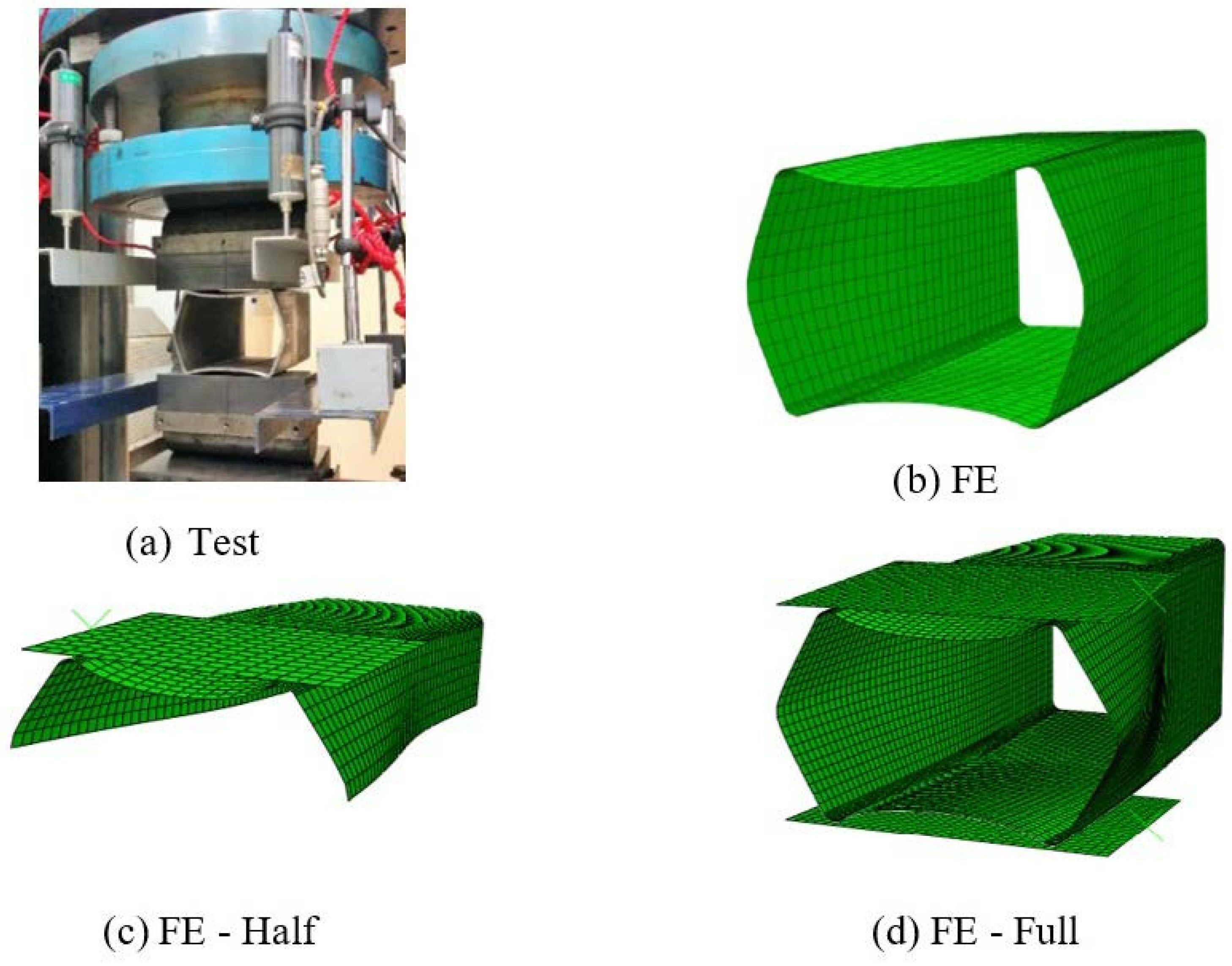
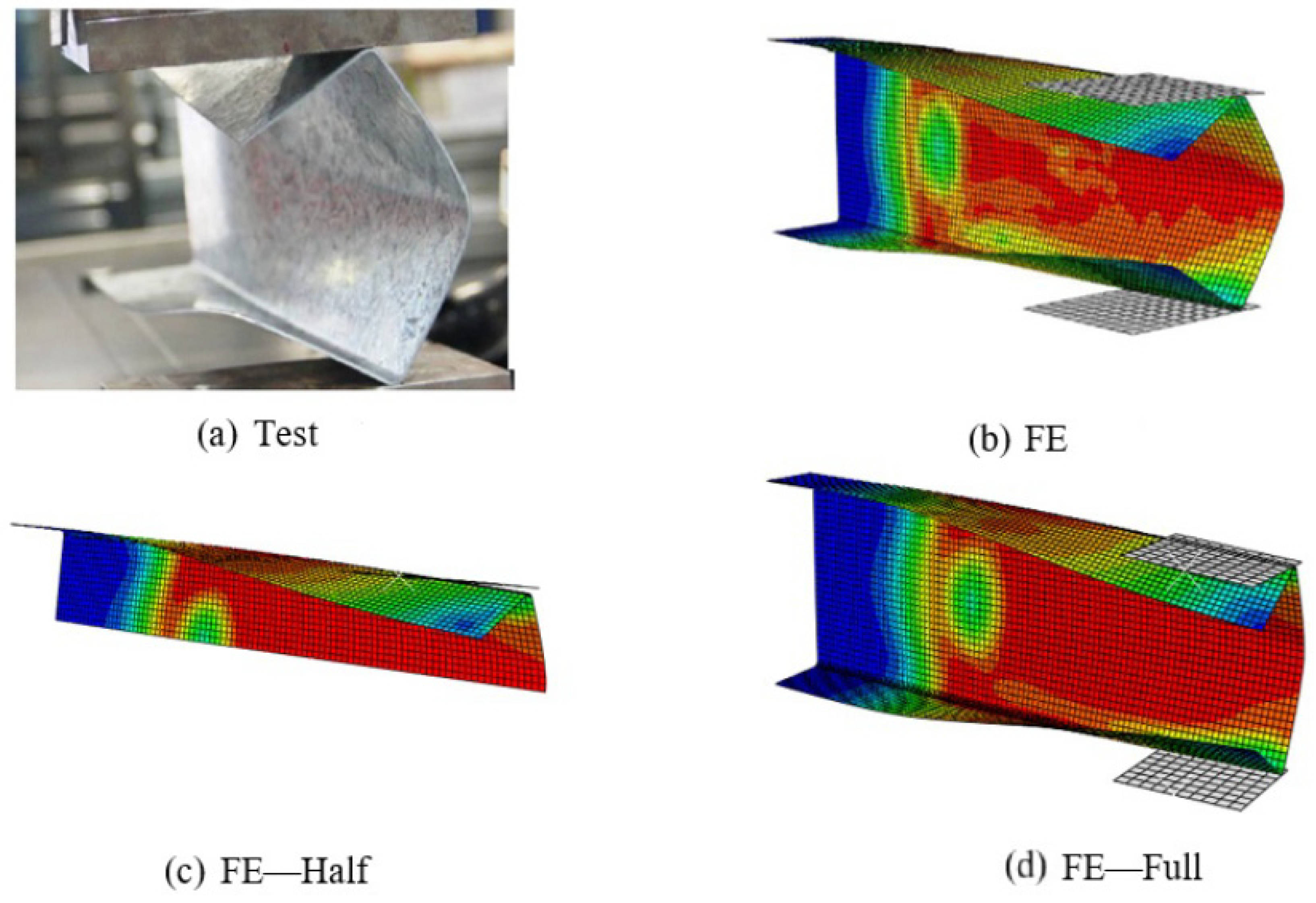
Finally, the validation was performed by comparing the failure modes. The failure mode of the tubular section (ETF H120X120X4 with a bearing plate length of 120 mm) and unlipped channel sections (ETF-UC10012 with 50 mm bearing plate, ETF-UC15015 with 100 mm bearing plate, ETF-UC20015 with 150 mm bearing plate) for both the full and half models was compared. A good agreement was observed and is illustrated in Figure 11, Figure 12, Figure 13 and Figure 14. The comparison shows that the failure modes of FE models match well with their experimental counterparts.
The comparison of FE models with experimental studies showed that the numerical model for both the full and half models is capable of predicting the web crippling capacity of cold-formed beams with high strength material under the ETF loading condition. However, reduced analysis time was observed for the half model in comparison to that of the full model, and thus half models were used to perform the parametric study of the cold-formed channel section with high strength undergoing web crippling under the ETF loading condition. Since accurate results were obtained in the validation, the parametric study was extended using numerical analyses.

4. Parametric Study

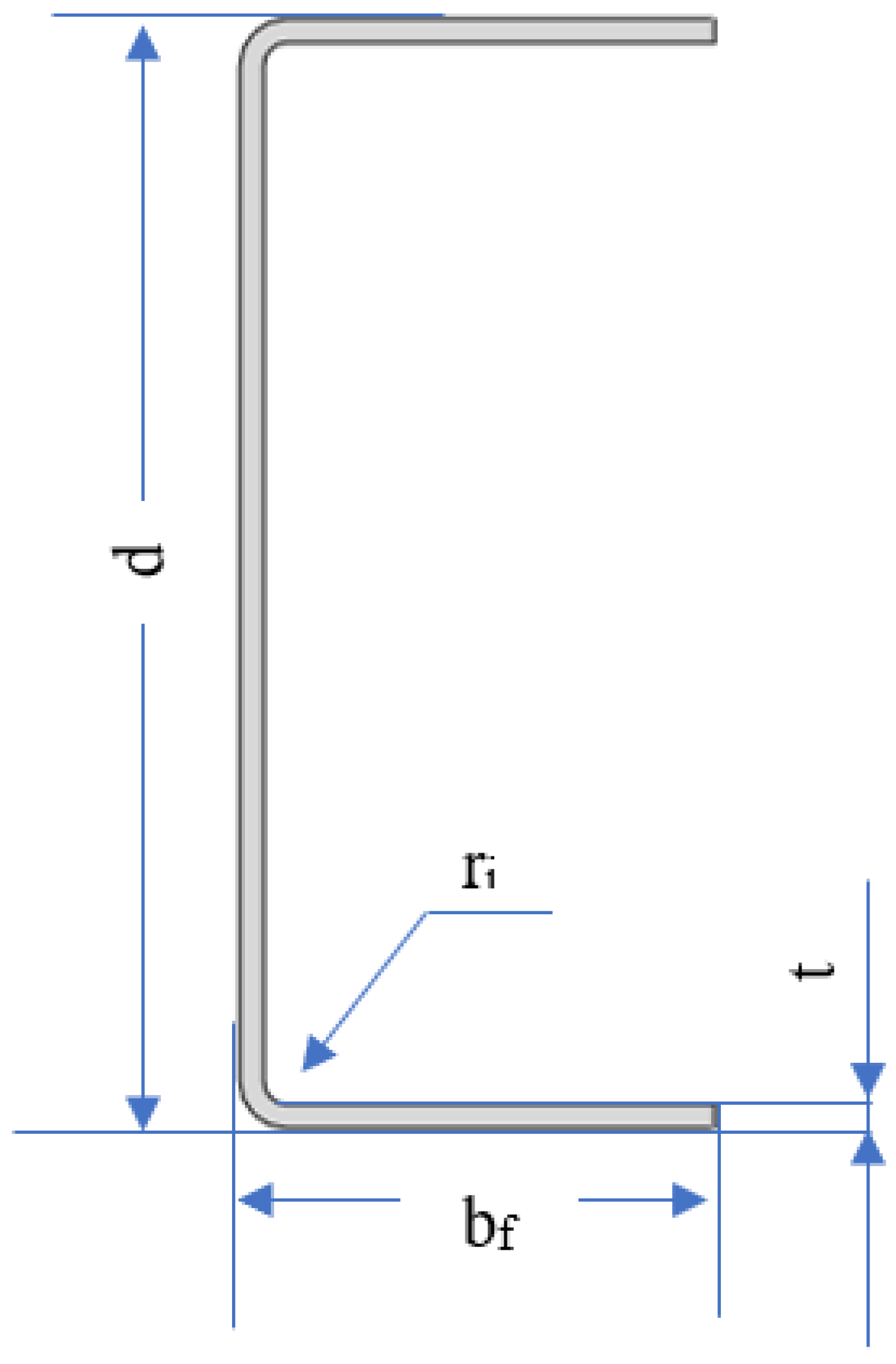
The validated FE models were incorporated in a comprehensive parametric study to generate a database of high strength steel unlipped channel sections subject to ETF loading to investigate their web crippling behaviour. The geometric and material parameters of section depth (d), width (bf), thickness (t), corner radius (ri), bearing length (N) and steel grade (fy) were varied during the study, covering a range of section slenderness values. Figure 15 shows the notations used for key cross-sectional dimensions of unlipped channel sections. The available web crippling design rules were then assessed, and improved design provisions were proposed to increase the accuracy of web crippling resistance predictions in succeeding sections using the generated database of unlipped channel sections.
Table 5 summarises the key parameters that were considered during the parametric study. Since high strength steel sections have been applied in various areas [56,57], the material strength was chosen by considering those applications and by focusing on the potential applications of high strength channel sections in the construction industry in the near future. Meanwhile, the geometric parameters of the parametric study were selected in accordance with commercially available channel sections. The section heights of unlipped channel sections varied between 150 mm and 250 mm, whilst the section thicknesses varied between 4 mm and 8 mm. The developed FE models had corner radii ranging from 12 mm to 18 mm, whilst bearing lengths varied from 50 mm to 150 mm. Three different yield stress values, from 700 MPa to 1000 MPa, were considered in the study. In total, 243 FE models of unlipped channel sections were generated during the parametric study.
The FE results, including web crippling resistances and failure modes of unlipped channel sections under the ETF loading case, are analysed in the coming sections to assess the web crippling behaviour and design provisions, with the aim of providing efficient design rules to increase the range of application of unlipped channel sections in structures.

5. Parametric Study Results

The ultimate web crippling capacity of lipped channel beams was obtained for 243 numerical studies. Figure 16 shows the typical web crippling failure modes of unlipped channel beams using corresponding pictures of the points indicated in the load vs. vertical deformation curve. The failure modes of the 200 mm section (t = 6 mm, N = 150 mm, ri = 12 mm and fy = 1000 MPa) are illustrated for the (i) initial, (ii) before-peak, (iii) at-peak and (iv) post-peak stages in Figure 16. The web crippling capacities of the 243 parametric studies are given in Table 6.
The effect of various parameters, such as section thickness (t), internal radius (ri) and bearing length (N) of the channel section, are investigated in the following subsections.

5.1. Effect of Thickness (t) on the Web Crippling Capacity

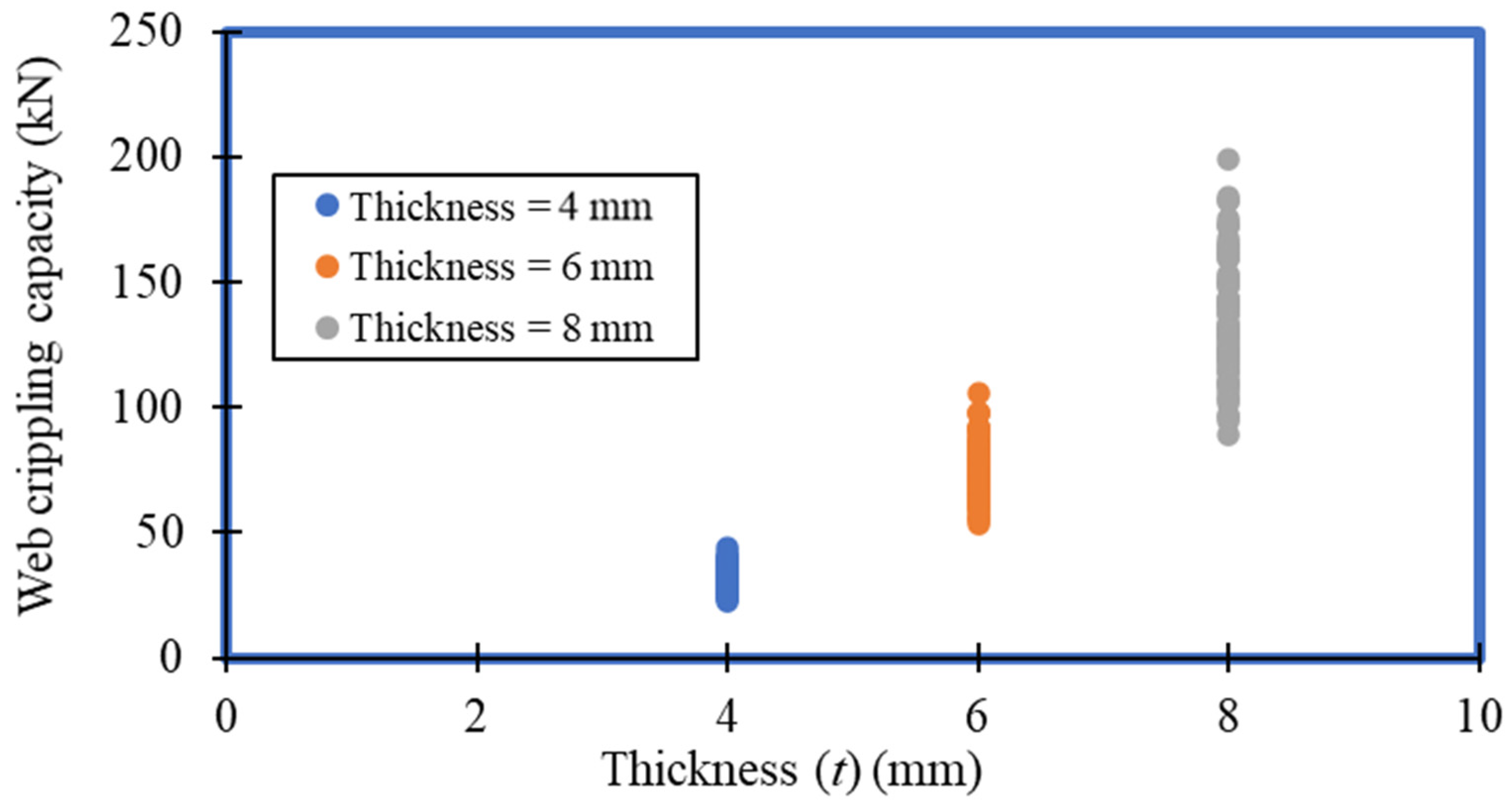
The web crippling behaviour of cold-formed steel sections varying in thickness is illustrated in Figure 17. It can be noticed that the web crippling strength increases with the thickness of the section. From the parametric results, the web crippling strengths of section 150 × 60 (ri = 12 mm, N = 50 mm and fy = 900 MPa) are 31.99 kN, 73.20 kN and 126.7 kN when thicknesses are 4 mm, 6 mm and 8 mm, respectively. Therefore, almost a 129% and 296% increment in web crippling strength was observed for the 6 mm and 8 mm thick sections, respectively, compared to the 4 mm thick sections in the corresponding study.

5.2. Effect of Internal Radius (ri) on the Web Crippling Capacity

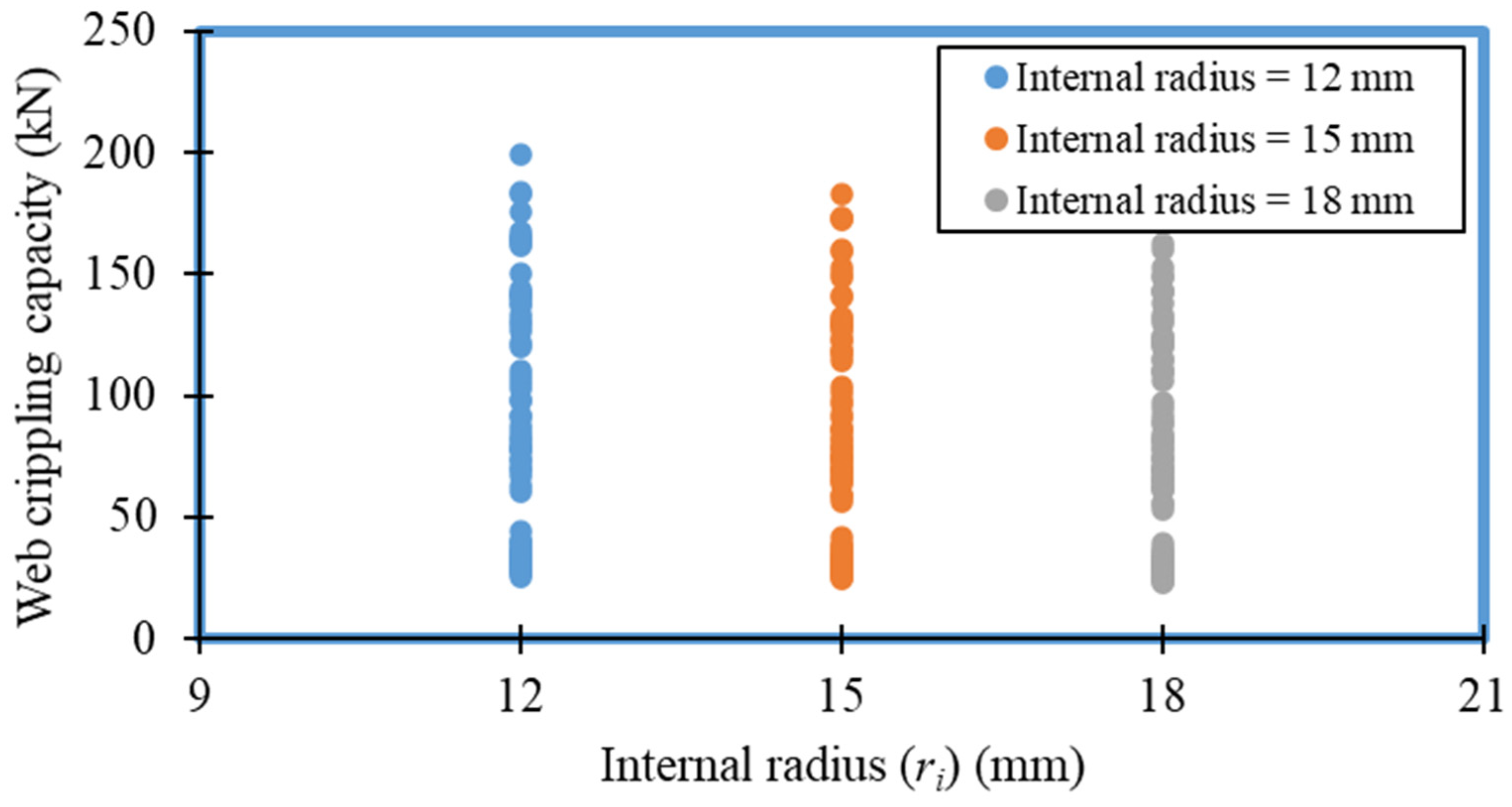
The effect of corner radius on the web crippling strength of cold-formed steel sections is shown in Figure 18. Figure 18 clearly depicts a reduction of the web crippling strength with corner radius. For example, the web crippling strength of section 150 × 60 (t = 4 mm, N = 50 mm and fy = 900 MPa) is decreased from 31.99 kN to 28.37 kN when the corner radius is increased from 12 mm to 18 mm. To the above-mentioned parametric study, web crippling strength is reduced by 5.8% and 11.3% for the sections with 15 mm and 18 mm corner radii, respectively, compared to the section with the 12 mm corner radius.

5.3. Effect of Bearing Length (N) on the Web Crippling Capacity

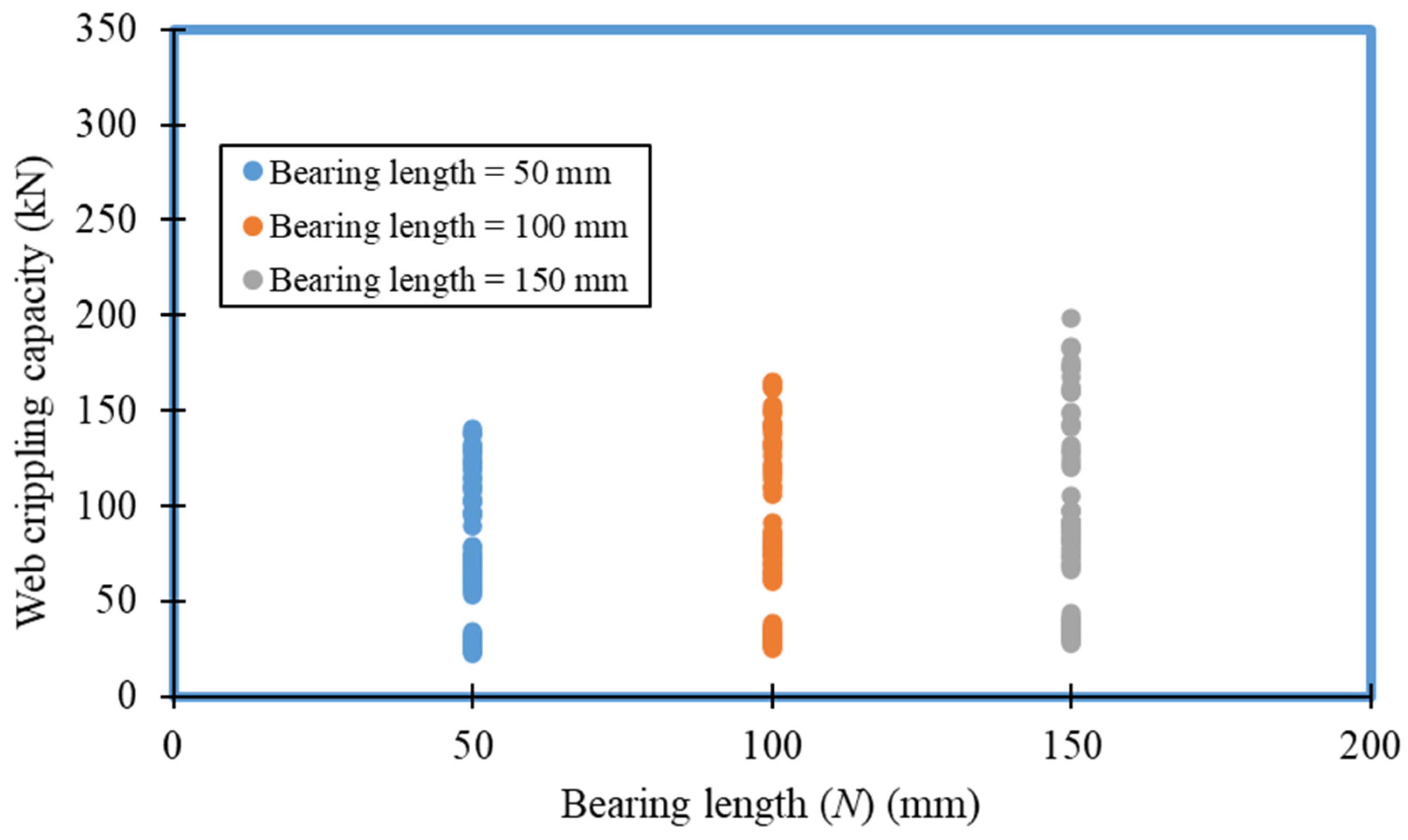
The web crippling capacity of cold-formed steel sections also depends on the bearing length of the loading and supporting plates. Figure 19 shows how the web crippling capacity of the unlipped channel section varies with the bearing length. An upward trend in web crippling capacity is noticed with an increase in the bearing length. The web crippling capacity of section 150 × 60 (t = 4 mm, ri = 12 m and fy = 900 MPa) with 50 mm bearing length is 31.99 kN, which is increased to 36.31 kN and 40.23 kN when the bearing length is increased to 100 mm and 150 mm, respectively. This shows an almost 14% and 26% increment in the 100 mm and 150 mm bearing plates, respectively, compared to the 50 mm bearing length in the corresponding study.
6. Evaluation of Current Design Rules

6.1. AISI S100-16 (NAS 2016) and AS/NZS 4600:2018

The web crippling design equations available in the design standards AISI S100 [13] and AS/NZS 4600 [14] are identical. The AISI S100 [13] and AS/NZS 4600 [14] recommend a unified equation to predict web crippling capacity with different coefficients, which is illustrated by Equation (11). The web crippling capacity of the cold-formed steel section is developed based on various parameters, such as flat portion of web to thickness ratio (d1/t), inside corner radius to thickness ratio (ri/t), bearing length to thickness ratio (N/t), section thickness (t), material strength (fy) and angle between the plane of the web and the bearing surface (θ). The coefficients vary depending on the (i) profiles, (ii) loading conditions and (iii) supporting conditions. In addition, the following variables are used: C—Coefficient, CR—Coefficient of inside bend radius, CN—Coefficient of bearing length and Ch—coefficient of slenderness. The parametric study results were compared with the prediction of the equation available in AISI S100 [13] and AS/NZS 4600 [14] (Figure 20). Mean and COV values were calculated for the fraction of FE to prediction of unified equation as available in AISI S100 [13] and AS/NZS 4600 [14]. The mean and COV were 0.62 and 0.11, respectively, and the comparison revealed that the codified equation is not capable of predicting the web crippling capacity of unlipped channel sections with high strength under the ETF loading condition with the unfastened supporting condition. The coefficients drawn from AISI S100 [13] are C = 2.00, CR = 0.11, CN = 0.37 and Ch = 0.01 for this study.
R b = C t 2 f y sin θ ( 1 C R r i t ) ( 1 + C N N t ) ( 1 C h d 1 t )

6.2. Eurocode 3 Part 1–3 (CEN 2006)

Eurocode 3 Part 1–3 (CEN 2006) [12] suggests using separate equations to load cases of ETF, ITF, EOF and IOF separately. The equations do not consider the supporting conditions, such as the use of flanges fastened for support. Equations available in the Eurocode 3 Part 1–3 (CEN 2006) were also used to check the applicability to this study (Figure 21). For the comparison, mean and COV values were calculated. The mean and COV were 0.7 and 0.23, respectively. Therefore, the authors concluded that Eurocode 3 Part 1–3 (CEN 2006) cannot be used to predict the web crippling capacity of unlipped channel sections with high strength under the ETF loading condition.
Even though AISI S100 [13] and AS/NZS 4600 [14] recommend a unified equation to predict the web crippling capacity with different coefficients by considering various cold-formed steel sections (all four loading conditions and supporting conditions), Eurocode 3 Part 1–3 (ECS, 2006) provides different design equations for each load case. Moreover, Eurocode 3 Part 1–3 (ECS, 2006) does not categorize the supporting conditions. The AISI S100 [13] and AS/NZS 4600 [14] equations are developed based on experimental results of Prabakaran et al. [58]. Those experiments used different specimen lengths and test procedures and did not consider the higher yield strength of the material. Meanwhile, the design rules available in the Eurocode 3 Part 1–3 (ECS, 2006) are developed based on the old AISI standard [59]. The design equations are not suitable for commercially available high strength sections due to the inconsistencies of past research and the parametric limitations in design standards.

6.3. Web Crippling Study of the Unlipped Channel Section

6.3.1. Gunalan and Mahendran Study

Gunalan and Mahendran [22] studied the web crippling capacity of unlipped channel sections under all four load cases. The study covered a section depth of 75 mm to 300 mm, thickness of 3.8 mm to 6.0 mm and corner radius of 4.0 mm to 8.0 mm and proposed modified coefficients to the codified equation available in AISI S100 [13] and AS/NZS 4600 [14]. The proposed coefficients were also compared in this study (Figure 22), and mean and COV of the comparison were 0.78 and 0.08, respectively. This study limited the investigation to 450 MPa, and due to the unsatisfied numerical facts, the study was also not suitable for calculating the web crippling capacity of unlipped channels with high strength material under the ETF load case.

6.3.2. Sundarajah Study

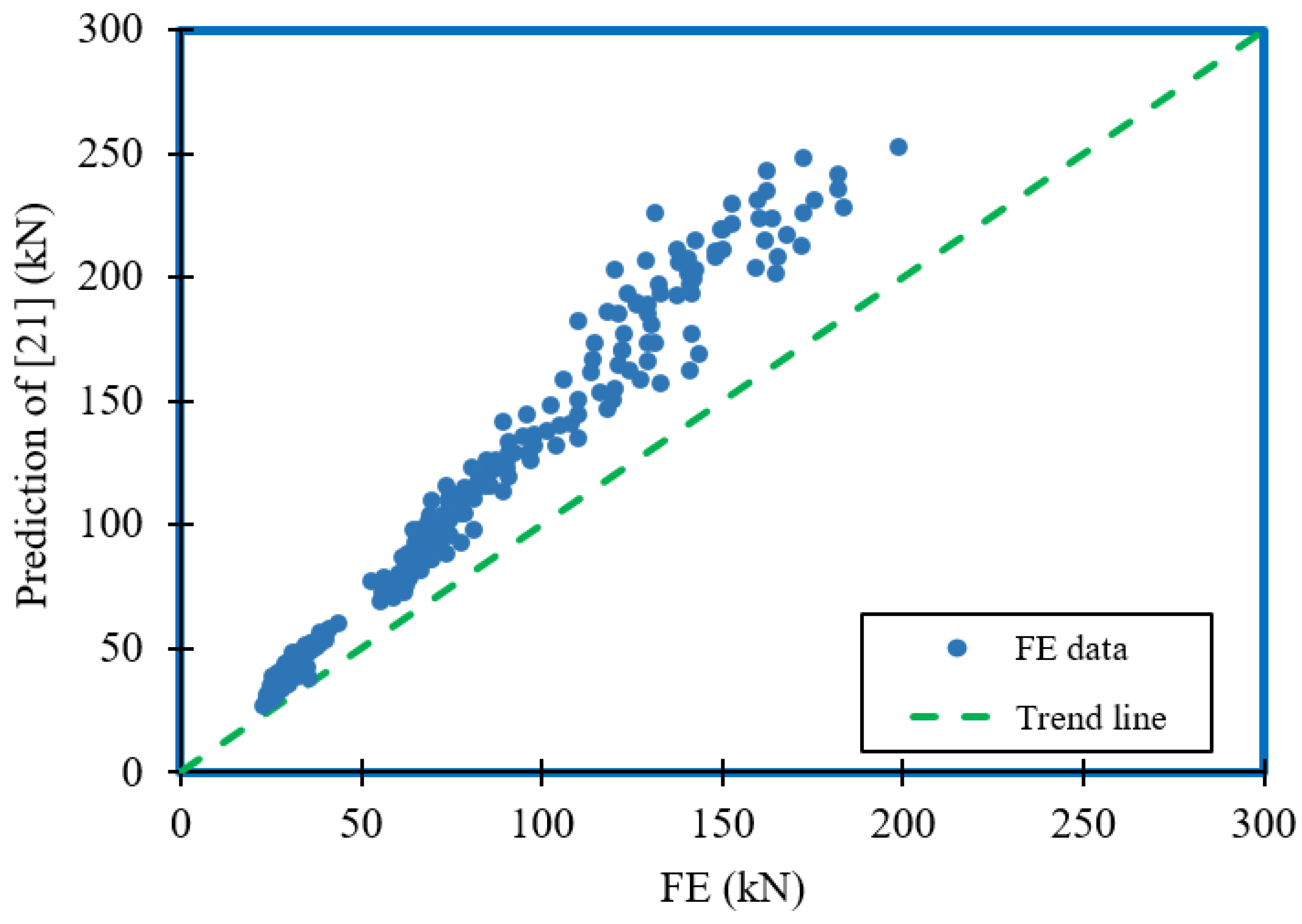
Sundararajah [21] also studied the web crippling capacity of unlipped channel sections under all four load cases. The study conducted by Sundararajah [20] accommodated a section depth of 100 mm to 250 mm, thicknesses of 1.0 mm to 2.4 mm and yield strengths of 506 and 581 MPa. The researchers proposed coefficients to the standard equation available in AISI S100 [13] and AS/NZS 4600 [14]. The proposed coefficients were also compared in this study, and mean and COV of the comparison for Sundararajah [21] were 0.74 and 0.08, respectively. Due to the parametric limitations of their research and the unsatisfactory comparison results to the parametric study, the authors concluded that the Sundarajah study [21] was also not suitable for calculating the web crippling capacity of unlipped channels with high strength material under the ETF load case. The comparison is illustrated in Figure 23.

7. Proposed Equations

7.1. Proposed Equation-1

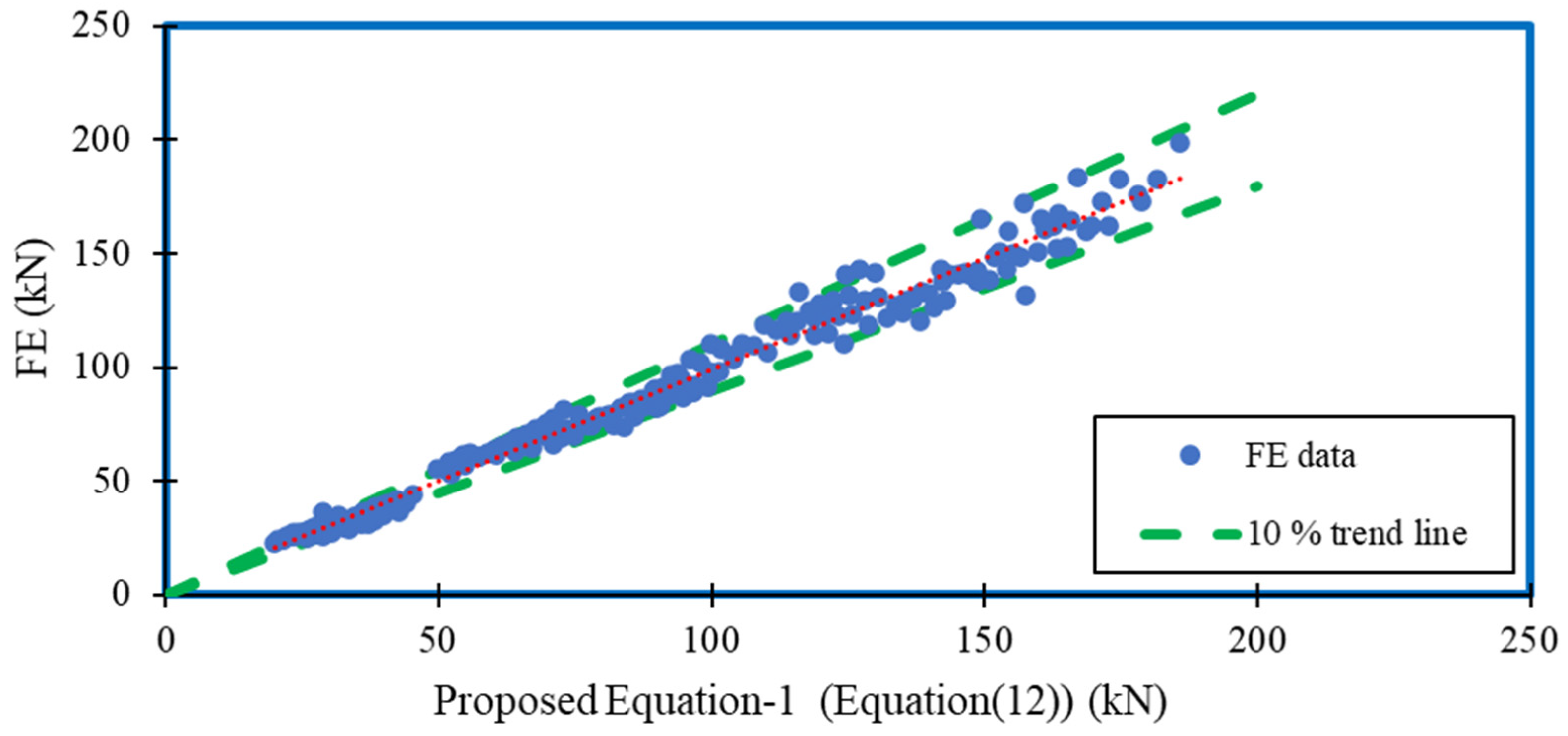
Based on a comparison with the current design equations, the equations proposed in the literature review were inadequate to predict the web crippling strength of unlipped channel sections with high strength under ETF loading conditions with unfastened supporting conditions. Therefore, the authors proposed coefficients to the design equation available in the design standards [13,14]. The proposed Equation-1 is illustrated by Equation (12). The mean, COV and capacity reduction factors (ϕw) were calculated for the comparison of the FE values to the proposal and were 1.00, 0.07 and 0.90, respectively. Therefore, the proposed equation (Equation (12)) can be used with a reduction factor (ϕw) of 0.9. The comparison of FE values to the prediction of the proposed equation is shown in Figure 24.
R b = 2.27 t 2 f y sin θ ( 1 0.21 r i t ) ( 1 + 0.21 N t ) ( 1 0.03 d 1 t )

7.2. Proposed Equation-2

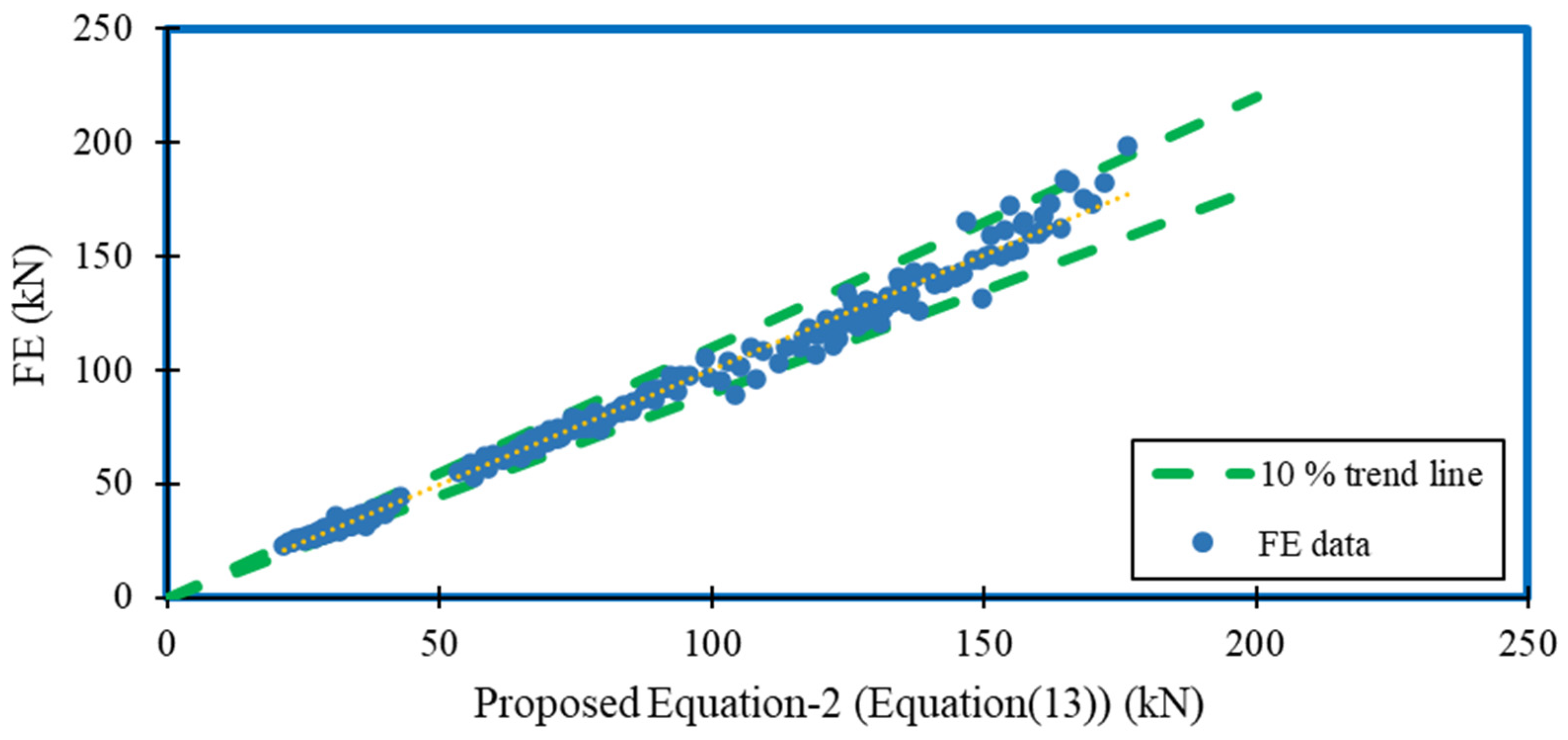
Previous studies on web crippling strength accommodate a strength factor (Cf) addition to the equation available in the design standards [19]. Therefore, strength factor was incorporated in this study to evaluate the web crippling strength of unlipped channel beams with high strength material. In addition, the incorporation of strength factor predicted the web crippling strength more accurately than previous equations (Proposed Equation-1 (Equation (12))). Proposed Equation-2 is illustrated by Equation (13). Mean, COV and capacity reduction factors (ϕw) were calculated to compare the parametric study to the prediction of proposed Equation-2. The mean and COV were 1.00 and 0.05, with a capacity reduction factor (ϕw) of 0.91. The comparison is illustrated in Figure 25. Therefore, both the proposed equations are capable of determining the web crippling capacity of unlipped channel beams with given reduction factors (ϕw) for high strength material under ETF loading conditions and unfastened support.
R b = 0.65 t 2 f y sin θ ( 1 0.21 r i t ) ( 1 + 0.21 N t ) ( 1 0.03 d 1 t ) ( 1 + 4.68 250 f y )

7.3. Direct Strength Method (DSM)

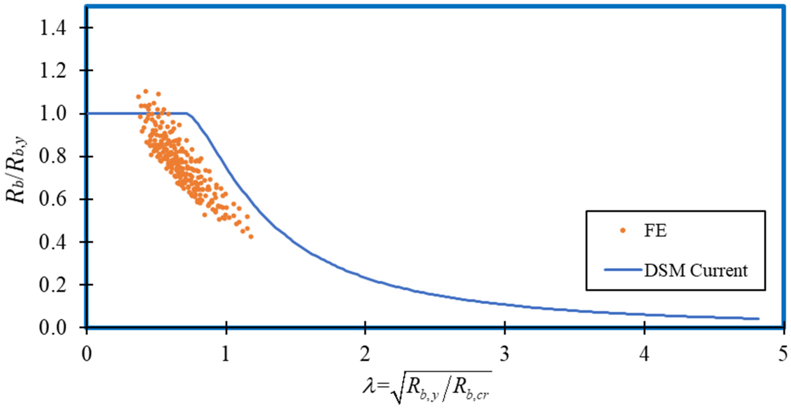
The design equations available in the current design rules were proposed and modified (Proposed Equation-1 and Proposed Equation-2) for this study to predict the web crippling capacity of unlipped channel sections with high strength material under the ETF load case with unfastened flanges to supporting plates. Few researchers [21,22,39] have proposed web crippling–based DSM equations. Keerthan and Mahendran [39] conducted crippling studies for LSB, whereas Gunalan and Mahendran [22] and Sundarajah [21] studied the web crippling behaviour of unlipped channel sections. The researchers obtained the critical buckling load (Rb,cr) and yield load (Rb,y) to develop their DSM equation. The yield load was derived based on the 45° load distribution, which was determined from the end of the bearing plate to middle of the web. A similar method was incorporated in this study to propose a DSM-based equation to predict the web crippling behaviour of unlipped channel sections under ETF loading conditions with high strength material. The DSM equation (Equations (14) and (15)) was proposed by Sundarajah [21], which was compared with this study to ensure the applicability of the equation. The mean and COV were observed as 1.28 and 0.13, respectively. The comparison revealed that Equations (14) and (15) were not suitable for predicting the web crippling strength of unlipped channel sections with high strength material under ETF loading conditions. The comparison is shown in Figure 26.
R b R b , y = 1       for   λ 0.71
R b R b , y = ( 1 0.25   ( 1 λ ) 2.0 ) ( 1 λ ) 2.0       for   λ > 0.71
where, λ = R b , y R b , c r .
A new DSM equation was proposed following the comparison of available equations. In this study, the critical buckling load (Rb,cr) was calculated based on Equation (16). The buckling coefficient (k) and yield load (Rb,y) were determined from Equations (17) and (18), respectively. The coefficients in the derivation of k value were determined from the Sundarajah study on unlipped channel sections [21]. Furthermore, the supporting equations to calculate the yield load (Rb,y) are given by Equations (19)–(21).
R b , c r = π 2 E k t w 3 12 ( 1 v 2 ) d
k = c b ( 1 C b , r r i t w ) ( 1 C b , w d 1 t w ) ( 1 C b , l l b t w ) ( 1 C b , b b f t w )
where Cb—General coefficient = 0.59, Cb,r—Coefficient of inside bent radius to thickness ratio = 0.01, Cb,w—Coefficient of web slenderness ratio = 0.05, Cb,l—Coefficient of bearing length to thickness ratio = 0.4 and Cb,b—Coefficient of flange width to thickness ratio = 0.01.
R b , y = f y N m ( 4 r m 2 + t w 2 2 r m )
N m = l b + 2.5 r e x t + 0.35 d 1
r m = r i + t 2
r e x t = r i + t
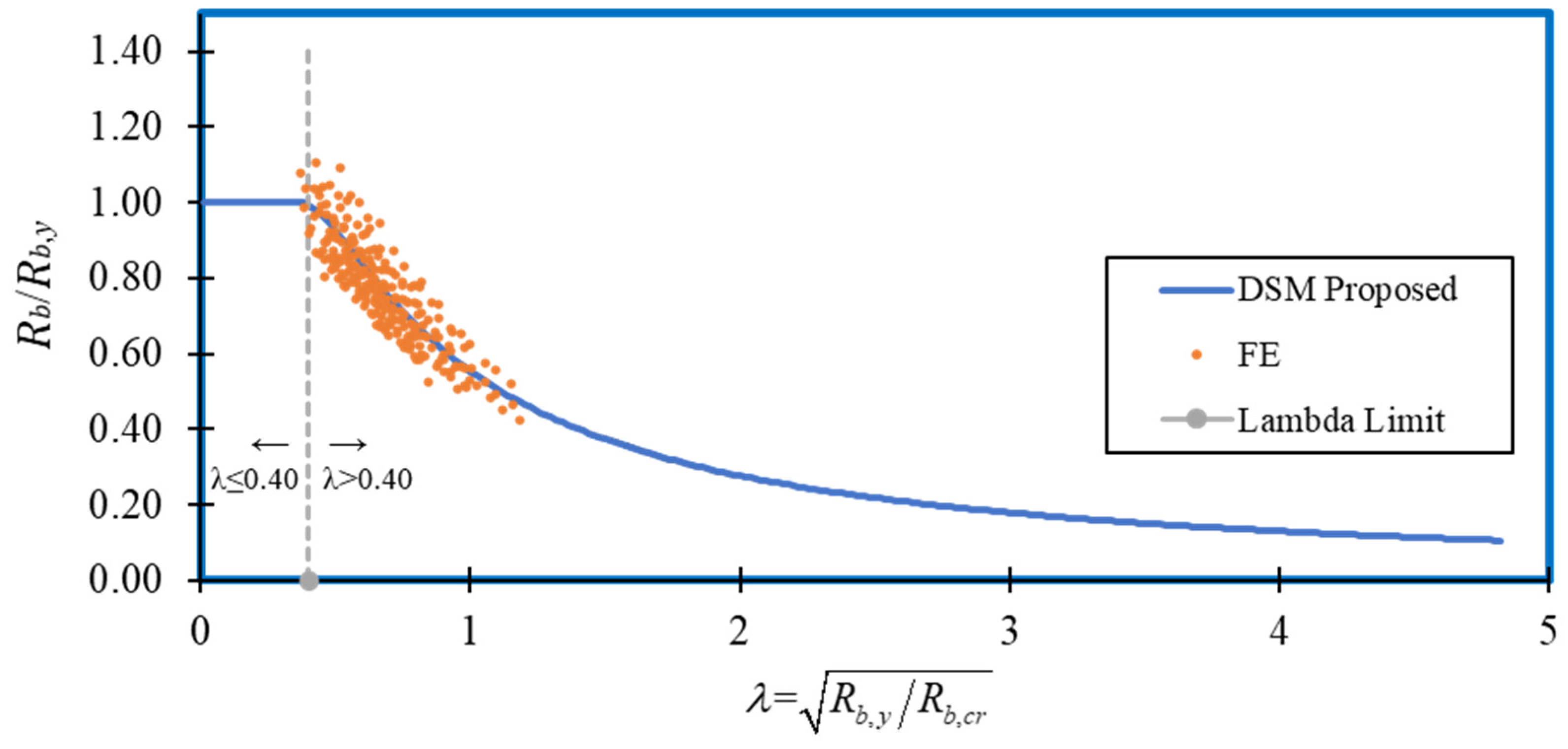
Based on the calculated critical buckling load (Rb,cr) and yield load (Rb,y), a DSM equation was developed and is given by Equations (22) and (23). Figure 27 compares the proposed DSM and FE results of unlipped channel sections with high strength under ETF loading conditions. The mean, COV and reduction factor (ϕw) of the comparison were 1.00, 0.06 and 0.91, respectively. Therefore, the proposed DSM can be used with the reduction factor (ϕw) to predict the web crippling capacities of unlipped channel sections with high strength material under the ETF loading case.
R b R b , y = 1   for   λ 0.40
R b R b , y = 0.67 ( 1 0.17   ( 1 λ ) 1.15 ) ( 1 λ ) 1.15   for   λ > 0.40

8. Conclusions

This paper presents a detailed investigation of the web crippling behaviour of high strength unlipped channel sections under the ETF load case. Earlier, a developed numerical model was validated with experiment results. Since the validation results showed great agreement with the experimental results, a parametric plan was developed to analyse the web crippling behaviour of unlipped channel sections with high strength under the ETF load case using ABAQUS. In total, 243 numerical models were developed to obtain the ultimate web crippling capacity of the sections by considering various parameters. The web crippling results were compared with the existing design code equations as well as equations proposed by various researchers in this respective area. Since the comparison discloses that available design equations are too conservative to predict the ultimate web crippling capacity under the ETF load case, a web crippling design equation according to the current design standards was proposed. Moreover, new design equations were proposed based on the DSM. This paper concludes with a modified equation with respect to current design standards and new DSM design equations, which accurately predicts the ultimate web crippling capacity of unlipped channel sections with high strength under the ETF load case.

Author Contributions

Conceptualization, K.P. and P.G.; methodology, E.K. and H.A.; software, E.K. and H.A.; formal analysis, E.K.; data curation, E.K.; writing-original draft preparation, E.K., K.T. and M.D.; writing-review and editing, K.P., P.G. and M.C.; supervision, K.P. All authors have read and agreed to the published version of the manuscript.

Funding

This research received no external funding.

Acknowledgments

The authors would like to acknowledge Northumbria University, The Home Engineers and European Research Council for generous support to conduct this research study.

Conflicts of Interest

The authors declare no conflict of interest.

Nomenclature

d1Flat portion of web
dDepth of the section
NBearing length
tSection thickness
riInside corner radius
EYoung’s modulus
E0.20.2% proof stress
εStrain
ε0.2Total strain at the yield strength
εuStrain at the ultimate strength fu (ultimate strain)
εc,avThrough thickness averaged plastic strain induced during the forming of the corner regions of press-braked and cold-rolled sections
fyMaterial yield strength
fYield stress
fuUltimate tensile strength
fy,cIncreased yield strength in the corners
nStrain hardening exponent
mStrain hardening exponent for the second part of the two-stage model
σ0.050.05% proof stress
pMaterial parameters
qMaterial parameters
CCoefficient
CRCoefficient of inside bend radius
CNCoefficient of bearing length
ChCoefficient of slenderness
w)Capacity reduction factors
CfStrength factor
RbWeb crippling strength
λSlenderness of the section
Rb,crCritical buckling load
Rb,yYield load
kBuckling coefficient
vPoisons ratio
CbGeneral coefficient
Cb,rCoefficient of inside bent radius to thickness ratio
Cb,wCoefficient of web slenderness ratio
Cb,lCoefficient of bearing length to thickness ratio
Cb,bCoefficient of flange width to thickness ratio
NmYield mechanism length
rmInside bent radius measured along the middle of the section
rextExternal bent radius
bfFlange width
θAngle between the plane of the web and the bearing surface
FEFinite Element
COVCoefficient of variation

References

  1. Yu, W.W. AISI Manual Cold-Formed Steel Design 2002 Edition. AISI-Specifications for the Design of Cold-Formed Steel Structural Members. 2003. Available online: https://scholarsmine.mst.edu/cgi/viewcontent.cgi?article=1131&context=ccfss-aisi-spec (accessed on 20 February 2022).
  2. Li, H.T.; Young, B. Design of cold-formed high strength steel tubular sections undergoing web crippling. Thin-Walled Struct. 2018, 133, 192–205. [Google Scholar] [CrossRef]
  3. Santaputra, C.; Parks, M.B.; Yu, W.W. Web-crippling strength of cold-formed steel beams. J. Struct. Eng. 1989, 115, 2511–2527. [Google Scholar] [CrossRef]
  4. Wu, S.; Yu, W.W.; LaBoube, R.A. Strength of flexural members using structural grade 80 of A653 steel (web crippling tests). In Civil Engineering Study 97–3; Cold-Formed Steel Series, Third Progress Report; University of Missouri-Rolla: Rolla, MO, USA, 1997. [Google Scholar]
  5. Li, H.T.; Young, B. Tests of cold-formed high strength steel tubular sections undergoing web crippling. Eng. Struct. 2017, 141, 571–583. [Google Scholar] [CrossRef]
  6. Winter, G.; Pian, R.H.J. Crushing Strength of Thin Steel Webs: Engineering Experiment Station, Bulletin No. 35; Cornell University: Ithaca, NY, USA, 1946. [Google Scholar]
  7. Zetlin, L. Elastic instability of flat plates subjected to partial edge loads. J. Struct. Div. ASCE Proc. 1955, 81, 1–24. [Google Scholar]
  8. Hetrakul, N.; Yu, W.W. Structural behavior of beam webs subjected to web crippling and a combination of web crippling and bending. In Civil Engineering Study 78–4; Final Rep.; University of Missouri-Rolla: Rolla, MO, USA, 1978. [Google Scholar]
  9. Wing, B.A.; Schuster, R.M. Web crippling for decks subjected to two flange loading. In 6th International Specialty Conference on Cold-Formed Steel Structures; Missouri University of Science and Technology: St. Louis, MO, USA, 1982. [Google Scholar]
  10. Santaputra, C.; Yu, W.W. Design of automotive structural components using high strength sheet steels: Web crippling of high strength cold-formed steel beams. In Eighth Progress Report, Civil Engineering Study 86–1; University of Missouri-Rolla: Rolla, MO, USA, 1986. [Google Scholar]
  11. Bakker, M.C.M. Web Crippling of Cold-Formed Steel Members. Ph.D. Thesis, Eindhoven University of Technology, Eindhoven, The Netherlands, 1992. [Google Scholar]
  12. EN 1993-1-3; Eurocode 3: Design of Steel Structures—Part 1–3: General Rules-Supplementary Rules for Cold-Formed Members and Sheeting. European Committee for Standardization (CEN): Brussels, Belgium, 2006.
  13. North American Specification (NAS). North American Specification for the Design of Cold-Formed Steel Structural Members; AISI S100-16; American Iron and Steel Institute (AISI): Washington, DC, USA, 2016. [Google Scholar]
  14. AS/NZS 4600; Cold-Formed Steel Structures. Standards Australia: Sydney, Australia, 2005.
  15. Sundararajah, L.; Mahendran, M.; Keerthan, P. Experimental studies of lipped channel beams subject to web crippling under two flange load cases. ASCE J. Struct. Eng. 2016, 142, 04016058. [Google Scholar] [CrossRef] [Green Version]
  16. Sundararajah, L.; Mahendran, M.; Keerthan, P. Web crippling experiments of high strength lipped channel beams under one-flange loading. J. Constr. Steel Res. 2017, 138, 851–866. [Google Scholar] [CrossRef]
  17. Sundararajah, L.; Mahendran, M.; Keerthan, P. Web crippling studies of SupaCee sections under two flange load cases. Eng. Struct. 2017, 153, 582–597. [Google Scholar] [CrossRef] [Green Version]
  18. Sundararajah, L.; Mahendran, M.; Keerthan, P. New Web Crippling Design Rules for Cold-Formed Steel Beams. In Proceedings of the Wei-Wen Yu International Specialty Conference on Cold-Formed Steel Structures 2018, St. Louis, MO, USA, 7–8 November 2018; pp. 99–114. [Google Scholar]
  19. Sundararajah, L.; Mahendran, M.; Keerthan, P. New design rules for lipped channel beams subject to web crippling under two-flange load cases. Thin-Walled Struct. 2017, 119, 421–437. [Google Scholar] [CrossRef] [Green Version]
  20. Sundararajah, L.; Mahendran, M.; Keerthan, P. Numerical modelling and design of lipped channel beams subject to web crippling under one-flange load cases. ASCE J. Struct. Eng. 2019, 145, 04019094. [Google Scholar] [CrossRef]
  21. Sundararajah, L. Web Crippling Studies of Cold-Formed Steel Channel Beams-Experiments, Numerical Analyses and Design Rules. Ph.D. Thesis, Queensland University of Technology, Brisbane, Australia, 2016. [Google Scholar]
  22. Gunalan, S.; Mahendran, M. Web crippling tests of cold-formed unlipped channel sections under two flange load cases. J. Constr. Steel Res. 2015, 110, 1–15. [Google Scholar] [CrossRef] [Green Version]
  23. Gunalan, S.; Mahendran, M. Experimental study of unlipped channel beams subject to web crippling under one flange load cases. Adv. Steel Constr. 2019, 15, 165–172. [Google Scholar]
  24. Janarthanan, B.; Mahendran, M.; Gunalan, S. Bearing capacity of cold-formed unlipped channel with restrained flanges under EOF and IOF load cases. Steel Constr. Des. Res. 2015, 8, 146–154. [Google Scholar] [CrossRef] [Green Version]
  25. Janarthanan, B. Structural Behaviour and Design of Cold-Formed Steel Floor Systems. Ph.D. Thesis, Queensland University of Technology, Brisbane, Australia, 2017. [Google Scholar]
  26. Janarthanan, B.; Mahendran, M.; Gunalan, S. Numerical modelling of web crippling failures in cold-formed steel unlipped channel sections. J. Constr. Steel Res. 2019, 158, 486–501. [Google Scholar] [CrossRef]
  27. Janarthanan, B.; Sundararajah, L.; Mahendran, M.; Keerthan, P.; Gunalan, S. Web crippling behaviour and design of cold-formed steel sections. Thin-Walled Struct. 2019, 140, 387–403. [Google Scholar] [CrossRef]
  28. Uzzaman, A.; Lim, J.B.P.; Nash, D.; Rhodes, J.; Young, B. Cold-formed steel sections with web openings subjected to web crippling under two-flange loading conditions-part I: Tests and finite element analysis. Thin-Walled Struct. 2012, 56, 38–48. [Google Scholar] [CrossRef] [Green Version]
  29. Uzzaman, A.; Lim, J.B.P.; Nash, D.; Rhodes, J.; Young, B. Effect of offset web holes on webcrippling strength of cold-formed steel channel sections under end-two-flange loading condition. Thin-Walled Struct. 2013, 65, 34–48. [Google Scholar] [CrossRef]
  30. Uzzaman, A.; Lim, J.B.P.; Nash, D.; Rhodes, J.; Young, B. Cold-formed steel sections with web openings subjected to web crippling under two-flange loading conditions-part II: Parametric study and proposed design equations. Thin-Walled Struct. 2012, 56, 79–87. [Google Scholar] [CrossRef] [Green Version]
  31. Uzzaman, A.; Lim, J.B.P.; Nash, D.; Rhodes, J.; Young, B. Web crippling behaviour of coldformed steel channel sections with offset web holes subjected to interior-two-flange loading. Thin-Walled Struct. 2012, 50, 76–86. [Google Scholar] [CrossRef] [Green Version]
  32. Lian, Y.; Uzzaman, A.; Lim, J.B.P.; Abdelal, G.; Nash, D.; Young, B. Effect of web holes on web crippling strength of cold-formed steel channel sections under endone-flange loading condition—Part I: Tests and finite element analysis. Thin-Walled Struct. 2016, 107, 443–452. [Google Scholar] [CrossRef] [Green Version]
  33. Lian, Y.; Uzzaman, A.; Lim, J.B.P.; Abdelal, G.; Nash, D.; Young, B. Effect of web holes on web crippling strength of cold-formed steel channel sections under endone- flange loading condition—Part II: Parametric study and proposed design equations. Thin-Walled Struct. 2016, 107, 489–501. [Google Scholar] [CrossRef] [Green Version]
  34. Lian, Y.; Uzzaman, A.; Lim, J.B.P.; Abdelal, G.; Nash, D.; Young, B. Web crippling behaviour of cold-formed steel channel sections with web holes subjected to interior-one-flange loading condition—Part I: Experimental and numerical investigation. Thin-Walled Struct. 2017, 111, 103–112. [Google Scholar] [CrossRef] [Green Version]
  35. Lian, Y.; Uzzaman, A.; Lim, J.B.P.; Abdelal, G.; Nash, D.; Young, B. Web crippling behaviour of cold-formed steel channel sections with web holes subjected to interior-one-flange loading condition—Part II: Parametric study and proposed design equations. Thin-Walled Struct. 2017, 114, 92–106. [Google Scholar] [CrossRef] [Green Version]
  36. Elilarasi, K.; Janarthanan, B. Effect of web holes on the web crippling capacity of cold-formed litesteel beams under end-two-flange load case. In Structures; Elsevier: Amsterdam, The Netherlands, 2020; Volume 25, pp. 411–425. [Google Scholar]
  37. Elilarasi, K.; Kasthuri, S.; Janarthanan, B. Effect of circular openings on web crippling of unlipped channel sections under end-two-flange load case. Adv. Steel Constr. 2020, 16, 310–320. [Google Scholar]
  38. Hareindirasarma, S.; Elilarasi, K.; Janarthanan, B. Effect of circular holes on the web crippling capacity of cold-formed LiteSteel beams under Interior-Two-Flange load case. Thin-Walled Struct. 2021, 166, 108135. [Google Scholar] [CrossRef]
  39. Keerthan, P.; Mahendran, M.; Steau, E. Experimental study of web crippling behaviour of hollow flange channel beams under two flange load cases. Thin-Walled Struct. 2014, 85, 207–219. [Google Scholar] [CrossRef] [Green Version]
  40. Sundararajah, L.; Mahendran, M.; Keerthan, P. Design of SupaCee sections subject to web crippling under one-flange load cases. J. Struct. Eng. 2018, 144, 04018222. [Google Scholar] [CrossRef]
  41. Uzzaman, A.; Lim, J.B.P.; Nash, D.; Roy, K. Web crippling behaviour of cold-formed steel channel sections with edge-stiffened and unstiffened circular holes under interior-two-flange loading condition. Thin-Walled Struct. 2020, 154, 106813. [Google Scholar] [CrossRef]
  42. Uzzaman, A.; Lim, J.B.P.; Nash, D.; Roy, K. Cold-formed steel channel sections under end-two-flange loading condition: Design for edge-stiffened holes, unstiffened holes and plain webs. Thin-Walled Struct. 2020, 147, 106532. [Google Scholar] [CrossRef]
  43. Chen, B.; Roy, K.; Fang, Z.; Uzzaman, A.; Chi, Y.; Lim, J.B.P. Web crippling capacity of fastened cold-formed steel channels with edge-stiffened web holes, un-stiffened web holes and plain webs under two-flange loading. Thin-Walled Struct. 2021, 163, 107666. [Google Scholar] [CrossRef]
  44. Fang, Z.; Roy, K.; Liang, H.; Poologanathan, K.; Ghosh, K.; Mohamed, A.M.; Lim, J.B. Numerical Simulation and Design Recommendations for Web Crippling Strength of Cold-Formed Steel Channels with Web Holes under Interior-One-Flange Loading at Elevated Temperatures. Buildings 2021, 11, 666. [Google Scholar] [CrossRef]
  45. Russell, M.J.; Lim, J.B.P.; Roy, K.; Clifton, G.C.; Ingham, J.M. Welded steel beam with novel cross-section and web openings subject to concentrated flange loading. Structures 2020, 24, 580–599. [Google Scholar] [CrossRef]
  46. Simulia. ABAQUS Standard User’s Manual; Version 6.14; Dassault Systèmes Simulia Corp.: Johnston, RI, USA, 2013. [Google Scholar]
  47. Arrayago, I.; Real, E.; Gardner, L. Description of stress-strain curves for stainless steel alloys. Mater. Des. 2015, 87, 540–552. [Google Scholar] [CrossRef]
  48. Tao, Z.; Rasmussen, K.J.R. Stress-strain model for ferritic stainless steels. J. Mater. Civil. Eng. ASCE 2015, 28, 06015009. [Google Scholar] [CrossRef] [Green Version]
  49. Afshan, S.; Rossi, B.; Gardner, L. Strength enhancements in cold-formed structural sections−Part I: Material testing. J. Constr. Steel Res. 2013, 83, 177–188. [Google Scholar] [CrossRef] [Green Version]
  50. Real, E.; Arrayago, I.; Mirambell, E.; Westeel, R. Comparative study of analytical expressions for the modelling of stainless steel behavior. Thin-Walled Struct. 2014, 83, 2–11. [Google Scholar] [CrossRef]
  51. Mirambell, E.; Real, E. On the calculation of deflections in structural stainless steel beams: An experimental and numerical investigation. J. Constr. Steel Res. 2000, 54, 109–133. [Google Scholar] [CrossRef]
  52. Abdel-Rahman, N.; Sivakumaran, K.S. Material properties models for analysis of cold-formed steel members. J. Struct. Eng. ASCE 1997, 123, 1135–1143. [Google Scholar] [CrossRef]
  53. Quach, W.M.; Huang, J.F. Stress-strain models for light gauge steels. Procedia Eng. 2011, 14, 288–296. [Google Scholar] [CrossRef] [Green Version]
  54. Gardner, L.; Xiang, Y. Description of stress-strain curves for cold-formed steels. Constr. Build. Mater. 2018, 189, 527–538. [Google Scholar] [CrossRef]
  55. Rossi, B.; Afshan, S.; Gardner, L. Strength enhancements in cold-formed structural sections—Part II: Predictive models. J. Constr. Steel Res. 2013, 83, 189–196. [Google Scholar] [CrossRef] [Green Version]
  56. IDI. Tokyo Gate Bridge. Japanese Infrastructure Newsletter; Infrastructure Development Institute: Tokyo, Japan, 2012. [Google Scholar]
  57. Collin, P.; Bernt, J. Bridges in High Strength Steel. In Proceedings of the IABSE Symposium: Responding to Tomorrow’s Challenges in Structural Engineering, Budapest, Hungary, 13–15 September 2006; Volume 92, pp. 1–9. [Google Scholar]
  58. Prabakaran, K. Web Crippling of Cold-formed Steel Sections; Project Report; Department of Civil Engineering, University of Waterloo: Waterloo, ON, Canada, 1993. [Google Scholar]
  59. AS/NZS 4600; Australia/New Zealand Standard for Cold-formed Steel Structures. Standards Australia/Standards New Zealand: Sydney, Australia, 1996.
Figure 1. Web crippling load cases [13].
Buildings 12 00291 g001
Figure 2. Experimental set-up for ETF load case [21].
Buildings 12 00291 g002
Figure 3. Finite Element model for full and half models.
Buildings 12 00291 g003
Figure 4. Applied element types and mesh sizes.
Buildings 12 00291 g004
Figure 5. Stress–strain curve for flat and corner regions (fy = 700 MPa).
Buildings 12 00291 g005
Figure 6. Boundary conditions of full and half models.
Buildings 12 00291 g006
Figure 7. Load–vertical deformation comparison of ETF H120X120X4 with a bearing plate length of 60 mm [2,5].
Buildings 12 00291 g007
Figure 8. Load–vertical deformation comparison of ETF-UC10012 with 50 mm bearing plate [21].
Buildings 12 00291 g008
Figure 9. Load–vertical deformation comparison of ETF-UC15015 with 100 mm bearing plate [21].
Buildings 12 00291 g009
Figure 10. Load–vertical deformation comparison of ETF-UC20015 with 150 mm bearing plate [21].
Buildings 12 00291 g010
Figure 11. Failure mode comparison for full and half models of ETF H120X120X4 with a bearing plate length of 120 mm [2].
Buildings 12 00291 g011
Figure 12. Failure mode comparison for full and half models of ETF-UC10012 with 50 mm bearing plate [21].
Buildings 12 00291 g012
Figure 13. Failure mode comparison for full and half models of ETF-UC15015 with 100 mm bearing plate [21].
Buildings 12 00291 g013
Figure 14. Failure mode comparison for full and half models of ETF-UC20015 with 150 mm bearing plate [21].
Buildings 12 00291 g014
Figure 15. Notations used for key cross-sectional dimensions.
Buildings 12 00291 g015
Figure 16. Typical web crippling failure modes of unlipped channel beam under progressive loading. (a) Initial stage. (b) Before peak stage. (c) At peak stage. (d) Post peak stage.
Buildings 12 00291 g016aBuildings 12 00291 g016b
Figure 17. Effect of thickness (t) on the web crippling strength.
Buildings 12 00291 g017
Figure 18. Effect of internal radius (ri) on the web crippling strength.
Buildings 12 00291 g018
Figure 19. Effect of bearing length (N) on the web crippling strength.
Buildings 12 00291 g019
Figure 20. Comparison of parametric results and codified Equation (Equation (11)) [13,14].
Buildings 12 00291 g020
Figure 21. Comparison between parametric results and prediction of Eurocode 3 Part 1–3 [12].
Buildings 12 00291 g021
Figure 22. Comparison of parametric results and equation developed by [22].
Buildings 12 00291 g022
Figure 23. Comparison of parametric results and equation developed by [21].
Buildings 12 00291 g023
Figure 24. Comparison between parametric results and proposed Equation-1 (Equation (12)).
Buildings 12 00291 g024
Figure 25. Comparison of parametric results and proposed Equation-2 (Equation (13)).
Buildings 12 00291 g025
Figure 26. Comparison of parametric results and available DSM equation [22].
Buildings 12 00291 g026
Figure 27. Comparison of parametric results and proposed DSM equation.
Buildings 12 00291 g027
Table 1. Strain-hardening exponents.
nm
Flat coupons7.63.8
Corner coupons7.04.2
Table 2. Comparison of web crippling test strengths with FE results for tubular sections under the ETF loading condition [2,5].
SpecimenExperimental (kN)FE Predictions—Full Model (kN)Experimental/FE—Full ModelFE Predictions—Half Model (kN)Experimental/FE—Half Model
H80X80X4N9075.777.90.9775.81.00
H80X80X4N5055.254.01.0254.61.01
H120X120X4N12079.683.50.9579.11.01
H120X120X4N6053.955.20.9856.00.96
H160X160X4N15072.680.20.9179.10.92
H160X160X4N9057.262.50.9260.00.95
V80X80X4N9087.394.70.9294.50.92
V80X80X4N5060.866.10.9265.10.93
V120X120X4N6055.962.90.8960.00.93
V120X120X4N12077.583.10.9385.00.91
Mean0.94 0.95
COV0.050.05
Note: H and V denotes the experimental study with a material strength of 700 MPa and 900 MPa respectively.
Table 3. Comparison of web crippling test strengths with FE results for unlipped channel sections under the ETF loading condition [21].
SpecimenBearing Length (mm)Experimental (kN)FE Predictions—Full Model (kN)Experimental/FE—Full ModelFE Predictions—Half Model (kN)Experimental /FE—Half Model
ETF-UC10012502.292.310.992.300.99
ETF-UC10015504.063.941.033.951.03
ETF-UC15012501.871.900.981.930.97
ETF-UC20012501.621.640.991.630.99
ETF-UC150151003.933.941.003.931.00
ETF-UC150121002.152.170.992.190.98
ETF-UC200121001.761.790.991.790.99
ETF-UC100151506.085.851.045.781.05
ETF-UC200121501.951.960.991.951.00
ETF-UC200151503.643.641.003.651.00
Mean1.00 1.00
COV0.020.03
Table 4. Summary of the statistical analysis of validation.
SpecimensExperimental/FE—Full ModelExperimental/FE—Half Model
MeanCOVMeanCOV
H. T. Li and B. Young [2,5]0.940.050.950.05
L. Sundararajah [21]1.000.021.000.03
Overall0.970.040.980.04
Table 5. Summary of key parameters considered.
Section (d × bf) (mm × mm)Thickness, t (mm)Corner Radius, ri (mm)Bearing Length, N (mm)Yield Strength, fy (MPa)No. of Models
150 × 604, 6, 812, 15, 1850, 100, 150700, 900, 100081
200 × 754, 6, 812, 15, 1850, 100, 150700, 900, 100081
250 × 854, 6, 812, 15, 1850, 100, 150700, 900, 100081
Total243
Table 6. Parametric study results.
No.Section (d × bf)Thickness (t)Corner Radius (ri)Bearing Length (N)Web Crippling Capacity (Rb) (kN)
(mm × mm)(mm)(mm)(mm)fy = 700 MPafy = 900 MPafy = 1000 MPa
1150 × 604125027.1131.9934.19
2150 × 604155025.6430.1431.55
3150 × 604185024.1128.3730.25
4150 × 6041210030.7736.3138.94
5150 × 6041510028.7234.3236.85
6150 × 6041810027.1032.3634.74
7150 × 6041215035.1440.2344.06
8150 × 6041515031.3438.7941.54
9150 × 6041815030.2836.3439.22
10150 × 606125060.6173.2078.94
11150 × 606155056.7269.0474.70
12150 × 606185053.1464.7470.07
13150 × 6061210070.6184.7691.20
14150 × 6061510065.0079.3385.52
15150 × 6061810061.4074.7680.69
16150 × 6061215081.4697.67105.38
17150 × 6061515074.9790.4597.80
18150 × 6061815069.7084.4791.26
19150 × 6081250103.16126.73137.77
20150 × 608155096.40118.81129.00
21150 × 608185089.28110.38120.34
22150 × 60812100121.77150.42162.20
23150 × 60815100114.06140.75152.56
24150 × 60818100106.52143.20131.46
25150 × 60812150141.70183.80198.93
26150 × 60815150131.46160.41172.98
27150 × 60818150122.40149.74162.51
28200 × 754125026.9130.8232.46
29200 × 754155025.6129.3230.74
30200 × 754185024.1627.3728.58
31200 × 7541210029.5934.236.21
32200 × 7541510028.1432.6234.55
33200 × 7541810026.7630.9732.65
34200 × 7541215032.6737.9240.24
35200 × 7541515036.0730.9138.42
36200 × 7541815029.3734.3436.52
37200 × 756125062.5873.3878.19
38200 × 756155059.2669.6974.13
39200 × 756185055.7565.4269.49
40200 × 7561210069.2874.5487.14
41200 × 7561510065.3477.3082.80
42200 × 7561810062.1478.8573.62
43200 × 7561215077.6291.3397.88
44200 × 7561515072.6386.1292.39
45200 × 7561815068.5481.7687.84
46200 × 7581250108.21130.88140.77
47200 × 7581550101.69123.21132.58
48200 × 758185095.06115.04123.89
49200 × 75812100133.46165.19164.07
50200 × 75815100116.54141.03150.6
51200 × 75818100109.86133.02143.23
52200 × 75812150143.40167.72182.69
53200 × 75815150129.41172.10182.67
54200 × 75818150124.57148.26159.95
55250 × 854125025.8028.4829.42
56250 × 854155024.4726.8027.55
57250 × 854185022.9324.8925.51
58250 × 8541210028.0131.5632.85
59250 × 8541510026.8130.0231.1
60250 × 8541810025.4528.1029.01
61250 × 8541215030.4334.5636.28
62250 × 8541515029.1433.0634.52
63250 × 8541815027.7831.2532.49
64250 × 856125061.8271.0074.83
65250 × 856155058.8067.3070.79
66250 × 856185055.3163.0866.21
67250 × 8561210067.0577.7482.44
68250 × 8561510063.9274.1878.69
69250 × 8561810060.9270.5274.54
70250 × 8561215073.5489.4090.89
71250 × 8561515069.7281.3186.48
72250 × 8561815066.4977.6882.53
73250 × 8581250109.95129.46137.53
74250 × 8581550103.80122.21129.83
75250 × 858185096.95114.23121.45
76250 × 85812100119.89141.73161.79
77250 × 85815100118.43126.48148.77
78250 × 85818100110.04129.70138.27
79250 × 85812150140.95165.36175.58
80250 × 85815150127.95159.60172.88
81250 × 85818150120.50142.68153.01
Publisher’s Note: MDPI stays neutral with regard to jurisdictional claims in published maps and institutional affiliations.