


Optimization of the Injection and Physical Properties of Sulfoaluminate Cement via the In Situ Polymerization of Acrylamide

Abstract
:1. Introduction
2. Experiment
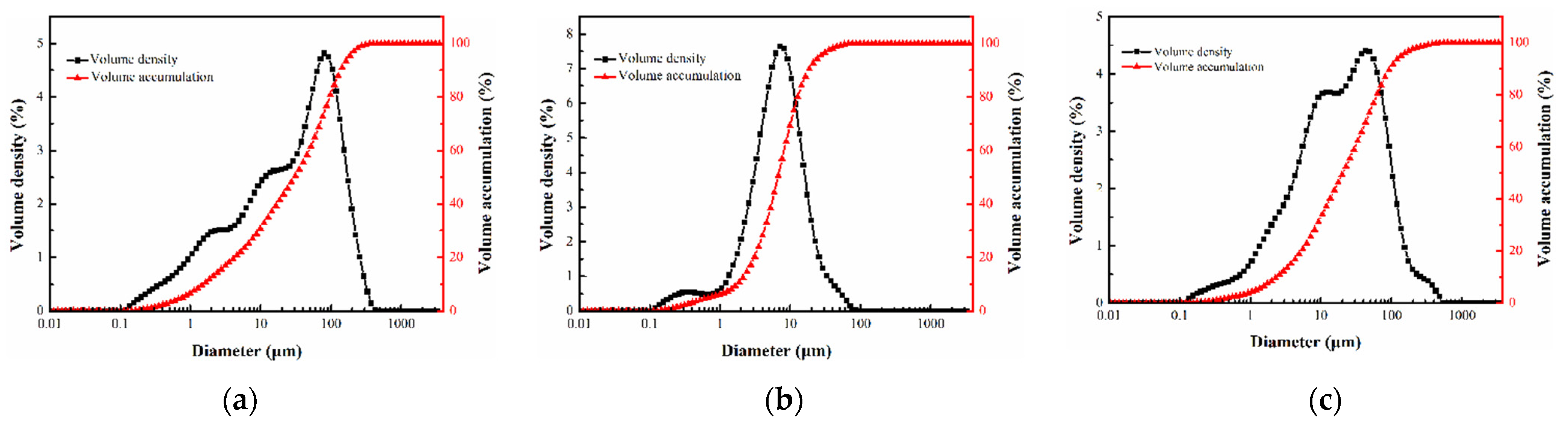
2.1. Experimental Materials
2.2. Sample Preparation
2.2.1. Experiment on the Optimization of the Yellow/White Material Ratio
2.2.2. Acrylamide Dosing Experiment
2.3. Test Methods
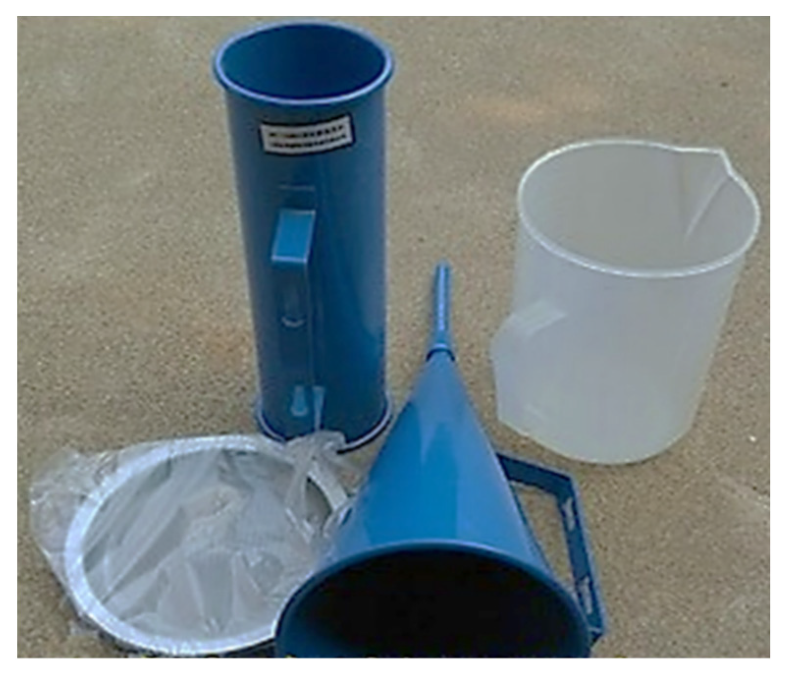
2.3.1. Fluidity
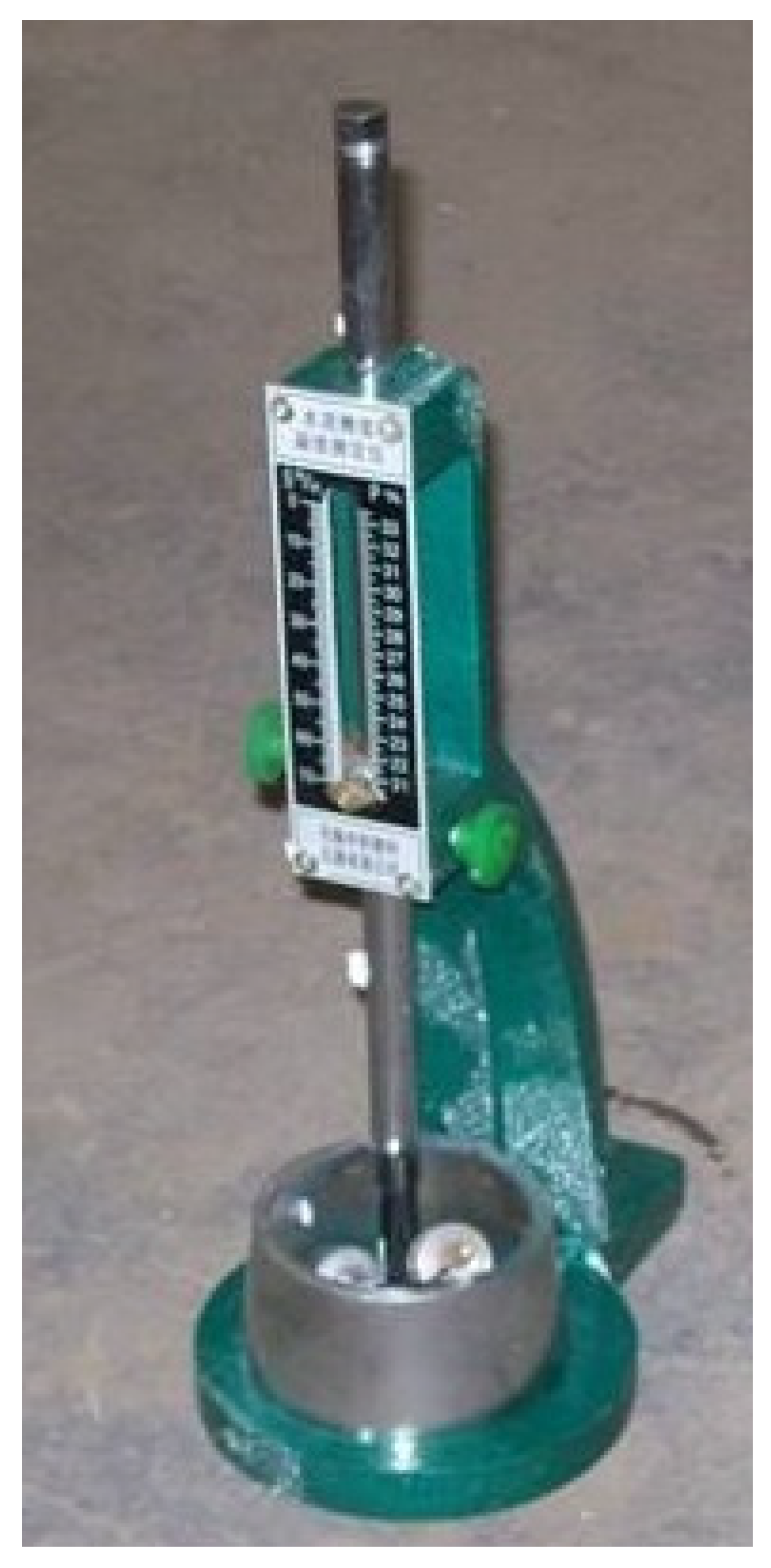
2.3.2. Setting Time
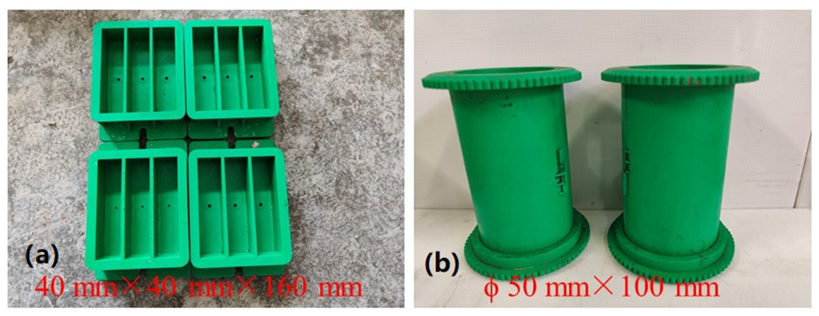
2.3.3. Compressive Strength and Flexural Strength
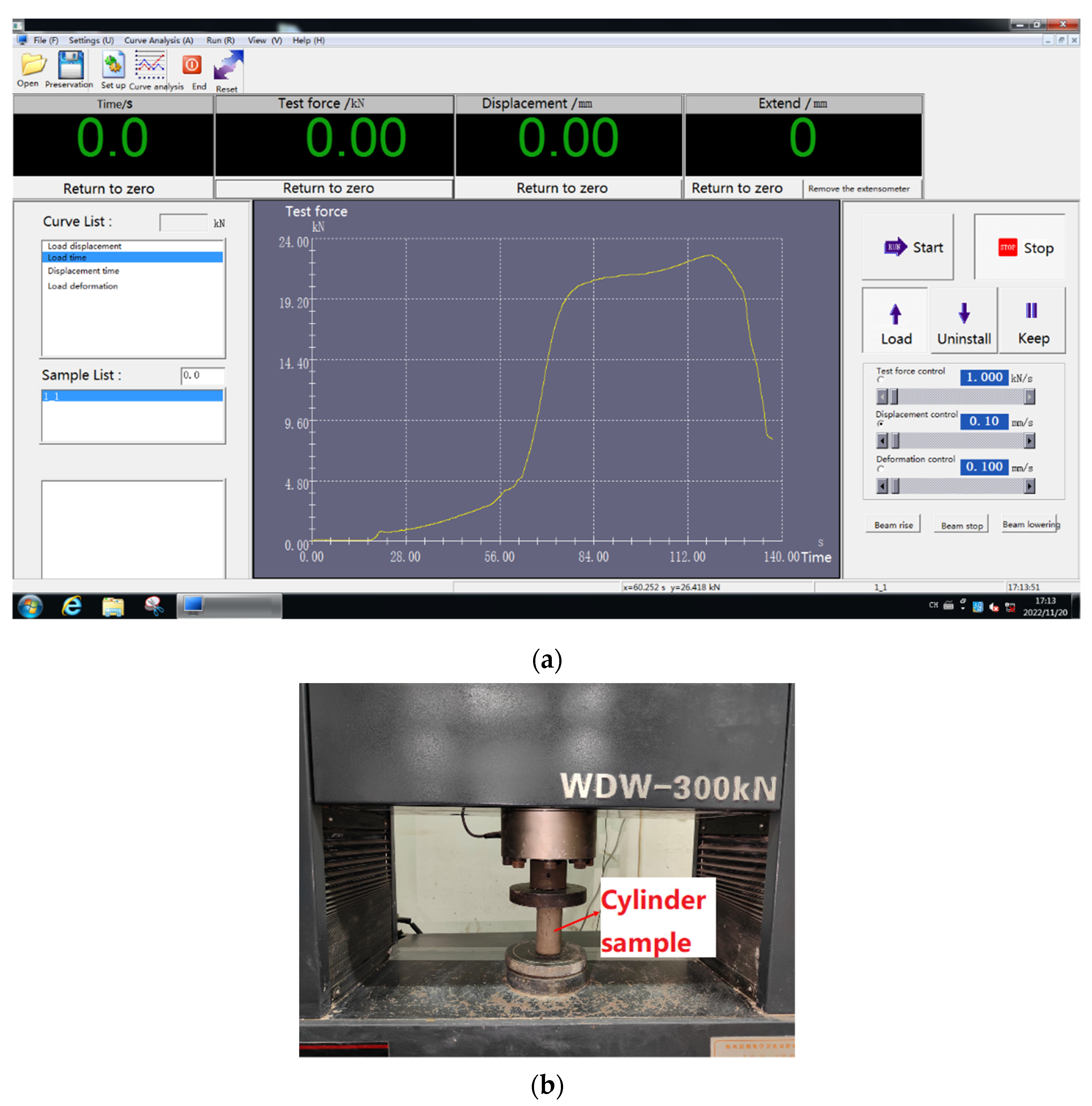
2.3.4. Axial Compression Strength
2.3.5. XRD
2.3.6. SEM
3. Results and Discussion
3.1. Effect of the Yellow/White Material Quality Ratio
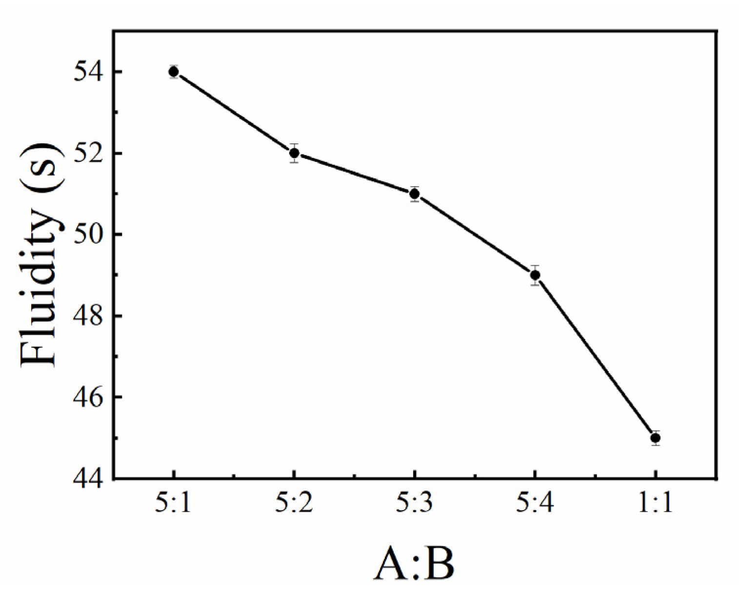
3.1.1. Fluidity
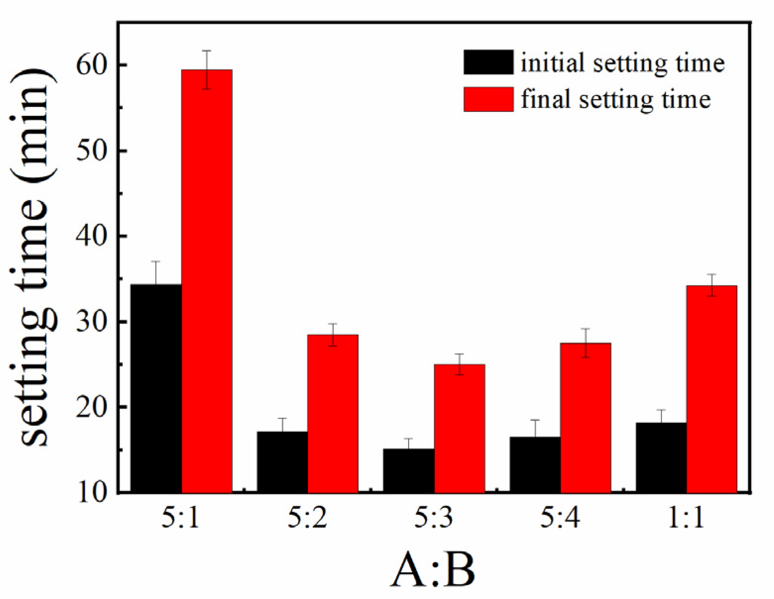
3.1.2. Setting Time
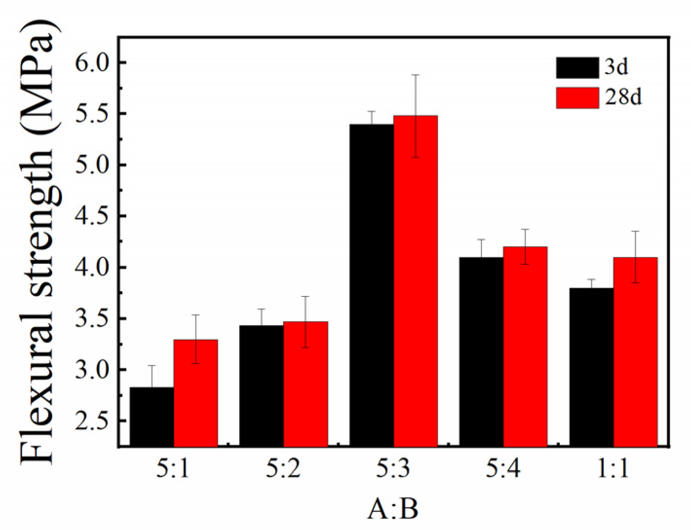
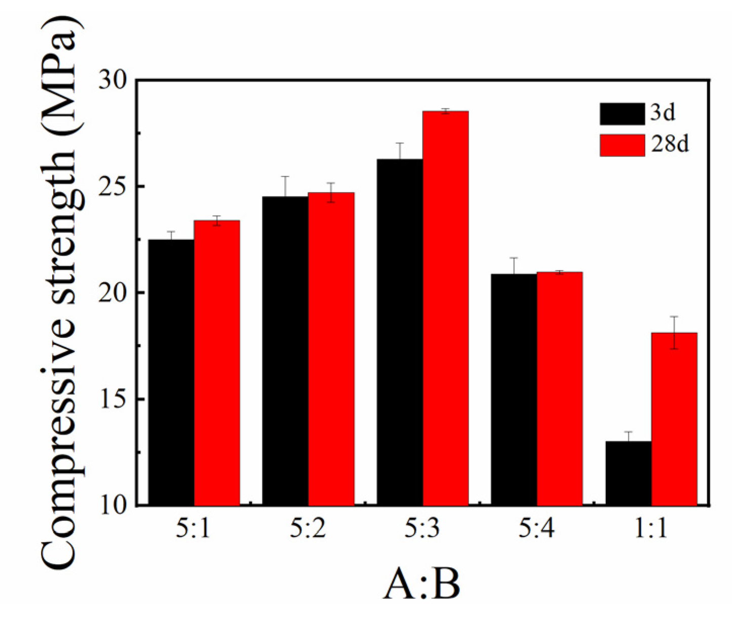
3.1.3. Flexural and Compressive Strengths
3.2. Effect of Acrylamide Dosing
3.2.1. Fluidity
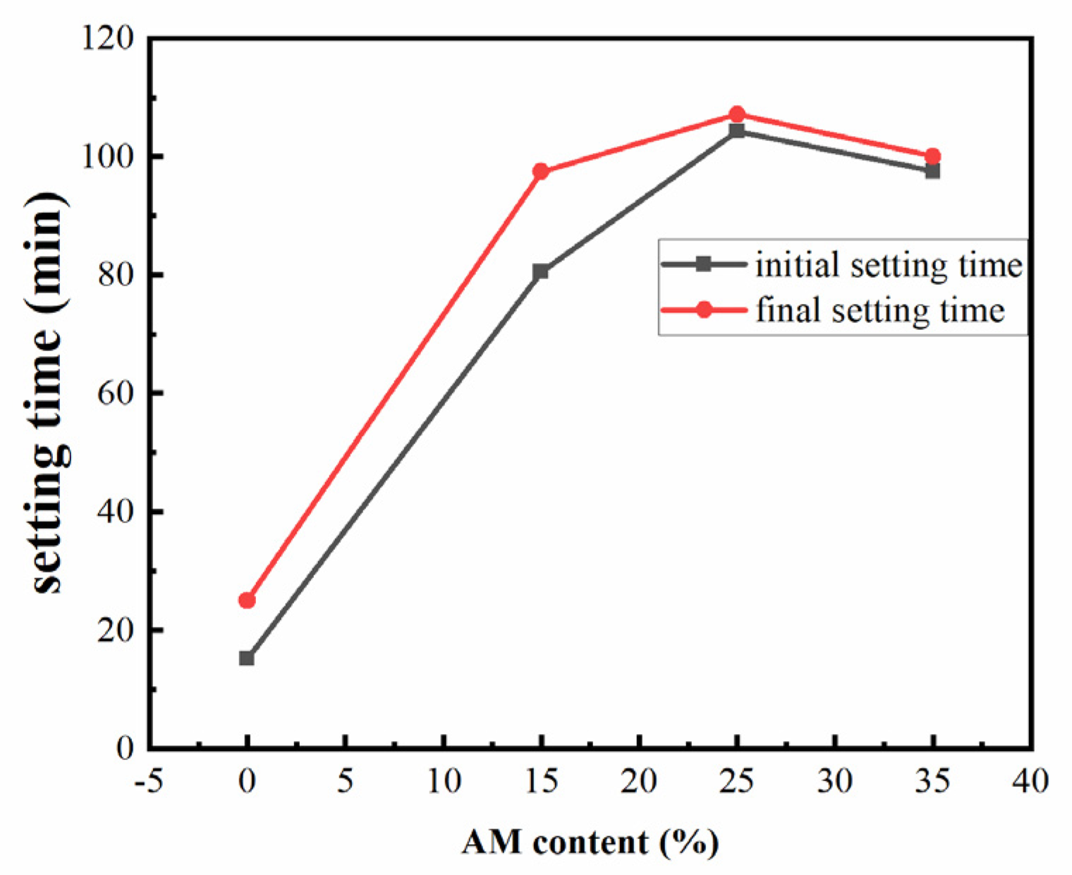
3.2.2. Setting Time
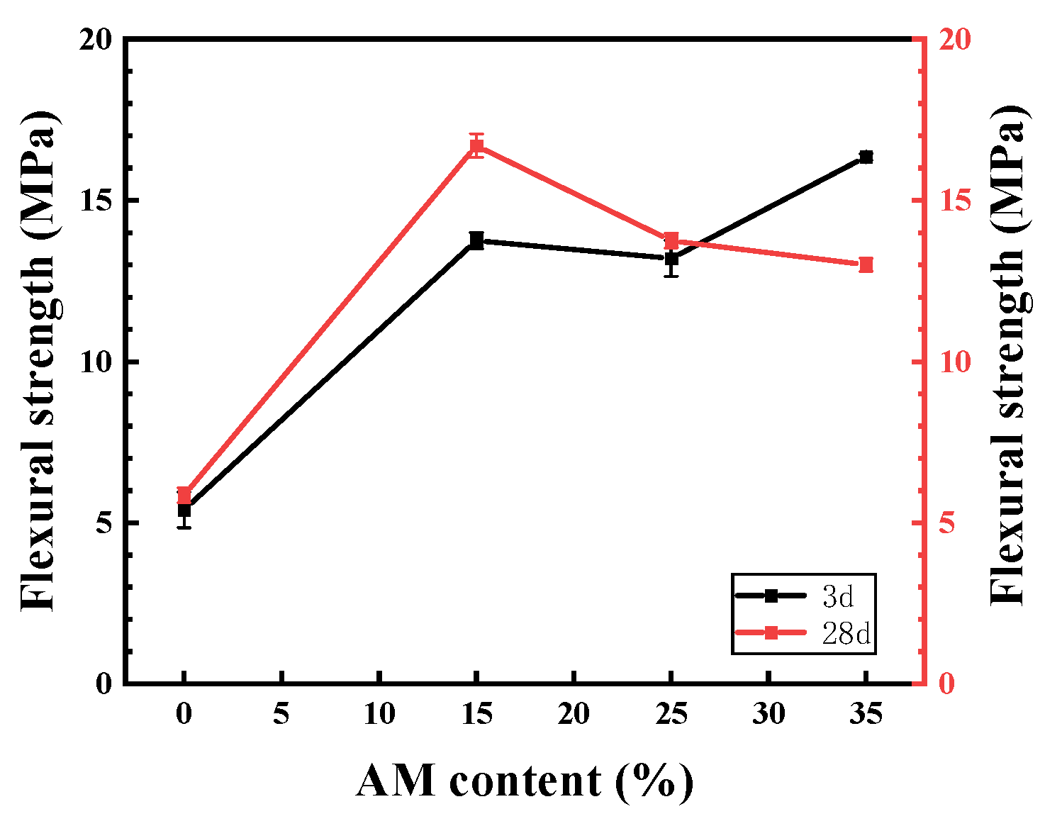
3.2.3. Flexural Strength
3.2.4. Uniaxial Compression Stress–Strain Curve
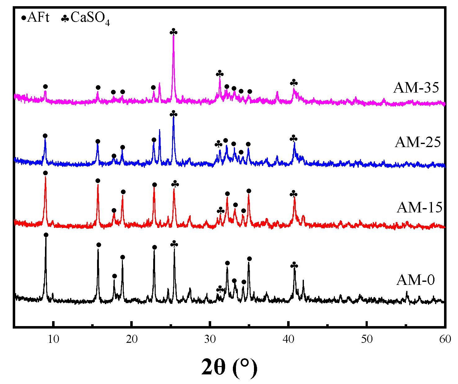
3.3. XRD Phase Analysis
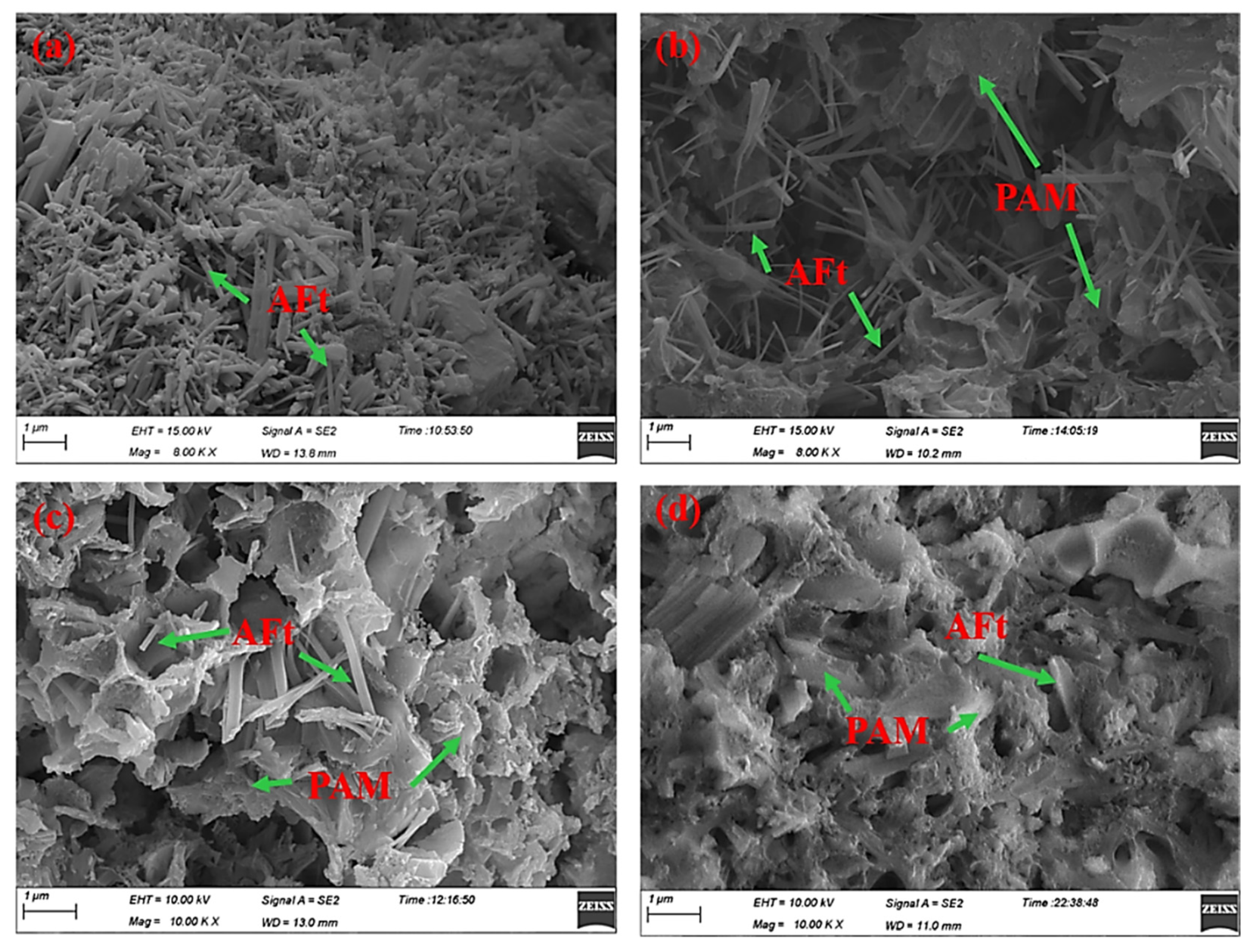
3.4. SEM Morphology Observations
3.5. Discussion
4. Conclusions
- (1)
- By adjusting the proportions of yellow and white materials in the sulfoaluminate cement, it was found that the overall structural strength was the highest after setting and hardening when the balance of yellow and white materials was 5:3;
- (2)
- With the increase in acrylamide content, the early viscosity of the slurry decreased significantly and the setting time increased significantly. This was in line with the purpose of improving the injectability of grout;
- (3)
- The uniaxial compressive stress–strain curve of the blank group specimens showed a brittle fracture characteristic. The acrylamide-doped group exhibited ductile fracture behavior, and the yield stress decreased with the increasing acrylamide. This meant that the requirements for optimizing the physical properties of the stones were met;
- (4)
- In this paper, the injectability and physical properties of AM regarding the in situ polymerization–modification of sulfoaluminate paste were analyzed, but the surface properties of the paste were not investigated. For coal and rock walls, the wettability of the paste directly affects the reinforcement effect. Therefore, the subsequent research should study the wetting effect of the paste on coal and rock walls from the perspective of the intermolecular force.
Author Contributions
Funding
Institutional Review Board Statement
Informed Consent Statement
Data Availability Statement
Conflicts of Interest
References
- Wang, X. Study on Control Technology and Application of Deep Fractured Coal Rock Grouting Reinforcement. Ph. D. Thesis, Southwest Petroleum University, Chengdu, China, 2018. [Google Scholar]
- Wang, F.; Zhang, C.; Wei, S.; Zhang, X.; Guo, S. Whole section anchor-grouting reinforcement technology and its application in underground roadways with loose and fractured surrounding rock. Tunning Undergr. Space Technol. 2016, 51, 133–143. [Google Scholar]
- Huang, Q. Research on Roof Structure and Rock Control in Longwall Mining of Shallow Buried Coal Seams; China University of Mining and Technology Press: Xuzhou, China, 2000; pp. 28–33. [Google Scholar]
- Guo, Y.; Zhang, B.L.; Zheng, X.G.; Zhou, W.; Wei, X.L.; Zhu, D.X. Grouting reinforcement technology of superfine cement with wind oxidation zone based on time-varying. J. Min. Saf. Eng. 2019, 36, 338–343, 350. [Google Scholar]
- Xu, X.; Yang, J.; Yang, S. Experimental research of reinforcing stopping tunnel for extremely soft thick coal seam in deep by grouting of ultra-fine cement materials. J. Henan Polytech. Univ. (Nat. Sci.) 2016, 35, 329–337. [Google Scholar]
- da Silva, Í.B.; Martinelli, A.E.; de Souza, W.R.M.; de Oliveira Freitas, J.C.; Rodrigues, M.A.F. Dilatometric behavior and crystallographic characterization of portland-polyurethane composites for oilwell high-temperature cementing applications. J. Pet. Sci. Eng. 2018, 169, 553–559. [Google Scholar] [CrossRef]
- Jiang, J.; Lu, Z.; Niu, Y.; Li, J. Investigation of the properties of high-porosity cement foams containing epoxy resin. Constr. Build. Mater. 2017, 154, 115–122. [Google Scholar] [CrossRef]
- Eren, F.; Gödek, E.; Keskinateş, M.; Tosun-Felekoğlu, K.; Felekoğlu, B. Effects of latex modification on fresh state consistency, short term strength and long term transport properties of cement mortars. Constr. Build. Mater. 2017, 133, 226–233. [Google Scholar] [CrossRef]
- Zhang, K.; Sun, Q. The use of wire mesh-polyurethane cement (WWM-PUC) composite to strengthen RC T-beams under flexure. J. Build. Eng. 2018, 15, 122–136. [Google Scholar] [CrossRef]
- Pang, B.; Zhang, Y.; Liu, G. Study on the effect of waterborne epoxy resins on the performance and microstructure of cement paste. Constr. Build. Mater. 2018, 167, 831–845. [Google Scholar] [CrossRef]
- Tang, J.; Liu, J.; Yu, C.; Wang, R. Influence of cationic polyurethane on mechanical properties of cement based materials and its hydration mechanism. Constr. Build. Mater. 2017, 137, 494–504. [Google Scholar] [CrossRef]
- Sun, K.; Wang, S.; Zeng, L.; Peng, X. Effect of styrene-butadiene rubber latex on the rheological behavior and pore structure of cement paste. Compos. Part B Eng. 2019, 163, 282–289. [Google Scholar] [CrossRef]
- Bosaris, G.D. Secondary Nucleation—A Review; Mullin, J.W., Ed.; Industrial Crystallization: New York, NY, USA, 1976. [Google Scholar]
- Geng, G.; Zhang, Y.; Bi, W.; Zeng, E.; Ma, R. Tudy on silicone modified epoxy cement pavement crack repair grouting material. China Concr. Cem. Produc. 2012, 11, 1–5. [Google Scholar]
- Li, F.; Gao, H.; Jiang, Y.; Wen, T.; Wang, J.; Yu, Y. Self repairing performance of cement-based materials mixed with magnesium acrylate. J. Southwest Jiaotong Univ. 2022, 57, 1055–1062. [Google Scholar]
- Wang, F.L.; Wang, Q.; Song, P.; Yang, Z.X.; Tian, L. Study of Calcium Acrylate on Compressive Strength and Hydration Process of Cement. Adv. Mater. Res. 2013, 816–817, 161–165. [Google Scholar] [CrossRef]
- Xu, S.; Zhao, N. Study on the strength and hydration heat release performance of rice husk ash/calcium acrylate composite modified cement. New Build. Mater. 2018, 45, 52–55. [Google Scholar]
- Liu, Q.; Liu, W.; Li, Z.; Guo, S.; Sun, G. Ultra-lightweight cement composites with excellent flexural strength, thermal insulation and water resistance achieved by establishing interpenetrating network. Constr. Build. Mater. 2020, 250, 118923. [Google Scholar] [CrossRef]
- Emad, W.; Salih, A.; Kurda, R. Stress-stain behavior, elastic modulus, and toughness of the soilcrete modified with powder polymers. Constr. Build. Mater. 2021, 295, 123621. [Google Scholar] [CrossRef]
- Wen, X.; Hu, Z.; Wang, S.; Zhang, Y.; Wang, Y. Preparation and performance study of crosslinked polycarboxylic acid water reducer. Mater. Rep. 2021, 35, 172–175. [Google Scholar]
- Liu, Z. Study on the Composition Design and Mechanism of Corrosion-Resistant Cements. Ph.D. Thesis, Jinan University, Jinan, China, 2011. [Google Scholar]
- Chu, Y.Y.; Song, X.F.; Zhao, H.X. Water-swellable, tough, and stretchable inorganic–organic sulfoaluminate cement/polyacrylamide double-network hydrogel composites. J. Appl. Polym. Sci. 2019, 136, 47905. [Google Scholar] [CrossRef]
- Liu, L.; Huang, T.; Wang, Z.; Liu, B. Effect of polyacrylamide on the microstructure and properties of mortar. Silic. Bull. 2020, 39, 2777–2788. [Google Scholar]
- Chen, B.; Qiao, G.; Hou, D.; Wang, M.; Li, Z. Cement-based material modified by in-situ polymerization: From experiments to molecular dynamics investigation. Compos. Part B Eng. 2020, 194, 108036. [Google Scholar] [CrossRef]
- Frenkel, D. Seeds of phase change. Nature 2006, 443, 641. [Google Scholar] [CrossRef] [PubMed]
- Yue, Y. Inorganic Chemistry; High Education Press: Beijing, China, 2006. [Google Scholar]
- Peng, J.; Lou, Z. Study on the Mechanism of Ettringite Formation. Bull. Chin. Ceram. Soc. 2000, 8, 511–515. [Google Scholar]
- Debenedetti, P.G. Metastable Liquids; Princeton University Press: Princeton, NJ, USA, 1996. [Google Scholar]
- Von Neumann, J. Metal Interfaces; American Society for Metals: Cleveland, OH, USA, 1952; pp. 108–110. [Google Scholar]
- Ted, L. Fracture Mechanics: Fundamentals and Applications; CRC Press: Boca Raton, FL, USA, 2017. [Google Scholar]
- Yu, X. Preparation of Large Temperature Difference Amphoteric Retarder and Its Application in Low Density Cement Slurry. Ph.D. Thesis, Southwest Petroleum University, Chengdu, China, 2016. [Google Scholar]
- Eoff, L.S. Set Retarding Additives, Cement Compositions and. Methods. Patent US5264470, 23 November 1993. [Google Scholar]
- Eoff, L.S.; Buster, D. High Temperature Synthetic Cement. Retarder. Patent SPE 28957, 14 February 1995. [Google Scholar]
- Diamond, S. Interactions between cement minerals and hydroxycarboxylic-acid retarders: I apparent adsorption of salicylic acid on cement and hydrated cement compounds. J. Am. Ceram. Soc. 1971, 54, 273–276. [Google Scholar] [CrossRef]
- Scales, P.J.; Johnson, S.B.; Healy, T.W.; Kapur, P.C. Shear yield stress of partially flocculated colloidal suspensions. AIChE J. 1998, 44, 538–544. [Google Scholar] [CrossRef]
- Nernst, W. Theorie der Reaaktionsgeschwindigkeit in heterogenen Systemen. Zeitschrift 37fur Physikalische Chem. 1904, 47, 52–55. [Google Scholar] [CrossRef]
- Ohama, Y. Polymer-base admixtures. Cem. Concr. Compos. 1998, 20, 189–212. [Google Scholar] [CrossRef]
- Brothers, L.; Lindsey, D.W.; Terry, D.T. Set retarded cement compositions and methods for well. cementing. Patent US4941536, 27 September 1991. [Google Scholar]
- Rodrigues, K.A.; Chatteriji, J. Cement Set Retarding Additives. Compositions and 31 Methods. Patent US 5421881, 14 January 1993. [Google Scholar]
- Kitagawa, M.; Zhou, D.; Qui, J. Stress-strain curves for solid polymers. Polym. Eng. Sci. 1995, 35, 1725–1732. [Google Scholar] [CrossRef]
- Wang, P.; Xu, Q.; Li, W. Effect of Hydroxyethyl Methylcellulose on Properties of Cement Mortar. J. Build. Mater. 2000, 4, 305–309. [Google Scholar]
- Anagnostopoulos, C.A.; Sapidis, G.; Papastergiadis, E. Fundamental Properties of Epoxy Resin-modified Cement Grouts. Constr. Build. Mater. 2016, 125, 184–195. [Google Scholar] [CrossRef]
- Jiang, C.; Wang, T.; Ding, Q.; Huang, S. Influence of polymer addition on performance and mechanical properties of lightweight aggregate concrete. Wuhan Univ. J. Nat. Sci. 2004, 9, 348–352. [Google Scholar]
- Zhang, C. Nonlinear mechanical response of high density polythylene (Part 1) Experimental investigation and model evalution. Polym. Eng. Sci. 1997, 37, 404–413. [Google Scholar] [CrossRef]
- Karas, L.J.; Wu, C.H.; Das, R.; Wu, J.I.C. Hydrogen Bond Design Principles. Wiley Interdiscip. Rev.-Comput. Mol. Sci. 2020, 10, e1477. [Google Scholar] [CrossRef]
- Gorninski, J.P.; Dal Molin, D.C.; Kazmierczak, C.S. Study of the modulus of elasticity of polymer concrete compounds and comparative assessment of polymer concrete and portland cement concrete. Cem. Concr. Res. 2004, 34, 2091–2095. [Google Scholar] [CrossRef]
- Zhang, K.; Xu, G.X.; You, J.Q. Effect of Epoxy Emulsion on the Mechanical Properties and Permeability of Cement Mortar. Adv. Mater. Res. 2013, 634–638, 2676–2679. [Google Scholar] [CrossRef]
- Zhong, S.; Chen, Z. Properties of latex blends and its modified cement mortars. Cem. Concr. Res. 2002, 32, 1515–1524. [Google Scholar] [CrossRef]
- Bureau, L.; Alliche, A.; Pilvin, P.; Pascal, S. Mechanical characterization of a styrene-butadiene modified mortar. Mater. Sci. Mater. Sci. Eng. A 2001, 308, 233–240. [Google Scholar] [CrossRef]
- Sakai, E.; Sugita, J. Compsite Mechanism of Polymer Modified Cement. Cem. Concr. Res. 1995, 27, 157–165. [Google Scholar]
- Jiang, H.; Shui, Z. Study on SBR-60 Polymer Cement Concrete. Concrete 2000, 11, 44–45. [Google Scholar]
- Jiang, H.; Liu, Z. Research of Polymer Cement Concrete. J. Wuhan Univ. Technol. 1996, 18, 37–39. [Google Scholar]
- Ogawa, K.; Roy, D.M. C4A3S Hydration, Ettringite Formation at Brewer Stadium, Boone, North Carolina. Cem. Concr. Aggreg. CCAGDP 1982, 4, 557–585. [Google Scholar]
- Oberholster, R.E.; Maree, H.; Brand, J.H.H. Alkali-Aggregate Reaction Concr. In Proceedings of the 9th International Conference The Concrete Society, Slough, UK, 27–31 July 1922. [Google Scholar]
- Scrivener, L. International Cement Microscopy Association. In Proceedings of the 18th International Conference Cement Microscopy, Duncansville, TX, USA, 24–26 October 1996. [Google Scholar]
- Hobbs, D.W. Ettingite-the Sometimes Host of Destruction; American Concrete Institute Intemational: Farmington Hills, MI, USA, 1999. [Google Scholar]
- Shayan, A.; Quick, G.W. Interna-tional Cement Microscopy Association. In Proceedings of the 16th International Conference Cement Microscopy, Interna-tional Cement Microscopy Association, Duncansville, TX, USA, 24–28 April 1994. [Google Scholar]
- Yan, P.; Qin, X.; Lian, H. The Influences of Delayed Ettringite Formation on the Properties of Massive Shrinkage—Com—Pensated Concrete. Cem. Concr. Res. 2004, 25, 687–693. [Google Scholar] [CrossRef]
- Taylor, H.F.W.; Famy, C.; Scrivener, K.L. Delayed ettringite formation. Cem. Concr. Res. 2001, 21, 683–693. [Google Scholar] [CrossRef]
- Hime, W.G. Clinker Sulfate: A Cause for Distress and a Need for Specification. Concrete for Environment Enhancecement and Protection; Khir, R.K., Dyer, T.D., Eds.; F. N. Spon: London, UK, 2006; pp. 387–395. [Google Scholar]
- Petrov, N.; Thibault, M.; Tagnit-Hamou, A. Expansion Due to DEF in Normally-Cured Concrete Heated by Cement Hydration. In Proceedings of the CANMET, Durability Meeting, Montreal, QC, Canada, 22 March 2006; pp. 237–249. [Google Scholar]
- Mehta, P.K. Durability of Concrete—The Zigzag Course of Progress. In Proceedings of the CANMET, Durability Meeting, Montreal, QC, Canada, 22 March 2006; pp. 69–72. [Google Scholar]
- Lawrence, B.L.; Myers, J.J.; Carrassquillo, R.L. Premature Concrete Deterioration in Texas Department of Transportation Precast Elements; American Concrete Institute: Farmington Hills, MI, USA, 1999; pp. 141–158. [Google Scholar]
- Famy, C. Expansion of Heat-Cured Mortars. Ph.D. Thesis, Purdue University, West Lafayette, IN, USA, 2006; pp. 196–197. [Google Scholar]
- Gartner, E.M.; Young, J.F.; Damidot, D.A.; Jawed. Struture and Performance of Cements, 2nd ed.; Bensted, J., Bames, P., Eds.; CRC Press: London, UK, 2002; pp. 57–113. [Google Scholar]
- Wang, A.; Li, F.; Yang, S. Effect of polyacrylamide application on runoff, erosion, and soil nutrient loss under simulated rainfall. Pedosphere 2011, 21, 628–638. [Google Scholar]
- Konietzko, A. Polymerspezifische Auswerkungen auf das Tragverhalten Modifizierter Zementgebundenen 38 Beton (PCC); Institut für Baustoffe, Massivbau und Brandschutz (IBMB): Braunschweig, Germany, 1988. [Google Scholar]
- Ke, G.; Zhang, J.; Xie, S.; Pei, T. Rheological behavior of calcium sulfoaluminate cement paste with supplementary cementitious materials. Constr. Build. Mater. 2020, 243, 118234–118242. [Google Scholar] [CrossRef]
- Zhang, H.; Zhou, R.; Liu, S.; Zhu, Y.; Wang, S.; Wang, J.; Guan, X. Enhanced toughness of ultra-fine sulphoaluminate cement-based hybrid grouting materials by incorporating in-situ polymerization of acrylamide. Constr. Build. Mater. 2021, 292, 123421. [Google Scholar] [CrossRef]


| Components | SiO2 | Al2O3 | Fe2O3 | CaO | MgO | SO3 | TiO2 |
|---|---|---|---|---|---|---|---|
| SAC | 8.59 | 29.97 | 3.86 | 45.21 | 1.03 | 9.44 | 1.90 |
| AN | 2.93 | 0.43 | 0.23 | 39.5 | 1.36 | 54.66 | 0.89 |
| LI | 8.46 | 2.67 | 1.07 | 80.7 | 7.1 | - | - |
| C4A3S | β-C2S(-) | C4AF | f-SO3 | CaO-TiO2 |
|---|---|---|---|---|
| 60.68 | 30.16 | 5.78 | 2.34 | 1.04 |
| A/g | B/g | Water/g | A:B |
|---|---|---|---|
| 2000 | 400 | 1440 | 5:1 |
| 2000 | 800 | 1680 | 5:2 |
| 2000 | 1200 | 1920 | 5:3 |
| 2000 | 1600 | 2160 | 5:4 |
| 2000 | 2000 | 2400 | 1:1 |
| Dosage | A+B/g | AM/g | MBA/g | AP/g | Water/g |
|---|---|---|---|---|---|
| 0% | 2560 | 0 | 0 | 0 | 1536 |
| 15% | 2560 | 384 | 3.84 | 7.68 | 1536 |
| 25% | 2560 | 640 | 6.40 | 12.8 | 1536 |
| 35% | 2560 | 896 | 8.96 | 17.92 | 1536 |
Publisher’s Note: MDPI stays neutral with regard to jurisdictional claims in published maps and institutional affiliations. |
© 2022 by the authors. Licensee MDPI, Basel, Switzerland. This article is an open access article distributed under the terms and conditions of the Creative Commons Attribution (CC BY) license (https://creativecommons.org/licenses/by/4.0/).
Share and Cite
Zhang, H.; Zhang, X.; Guo, Z.; Chai, H. Optimization of the Injection and Physical Properties of Sulfoaluminate Cement via the In Situ Polymerization of Acrylamide. Buildings 2022, 12, 2237. https://doi.org/10.3390/buildings12122237
Zhang H, Zhang X, Guo Z, Chai H. Optimization of the Injection and Physical Properties of Sulfoaluminate Cement via the In Situ Polymerization of Acrylamide. Buildings. 2022; 12(12):2237. https://doi.org/10.3390/buildings12122237
Chicago/Turabian StyleZhang, Haibo, Xiaotian Zhang, Zhiying Guo, and Hucheng Chai. 2022. "Optimization of the Injection and Physical Properties of Sulfoaluminate Cement via the In Situ Polymerization of Acrylamide" Buildings 12, no. 12: 2237. https://doi.org/10.3390/buildings12122237
APA StyleZhang, H., Zhang, X., Guo, Z., & Chai, H. (2022). Optimization of the Injection and Physical Properties of Sulfoaluminate Cement via the In Situ Polymerization of Acrylamide. Buildings, 12(12), 2237. https://doi.org/10.3390/buildings12122237