Article

Pragmatic Design Decision Support for Additive Construction Using Formal Knowledge and Its Prospects for Synergy with a Feedback Mechanism

TUM School of Engineering and Design, Technical University of Munich, 80333 Munich, Germany
*
Author to whom correspondence should be addressed.
Buildings 2022, 12(12), 2072; https://doi.org/10.3390/buildings12122072
Submission received: 4 November 2022 / Revised: 21 November 2022 / Accepted: 23 November 2022 / Published: 25 November 2022
(This article belongs to the Special Issue Architectural Design Supported by Information Technology)

Abstract

:
The construction industry has long been labor-intensive, with slow productivity growth and a significant environmental impact. In this regard, the ever-increasing practices of additive manufacturing (AM) in construction have presented a variety of advantages and are deemed one of the critical technologies for the concept of Construction 4.0. Building information modeling (BIM) as an enabler for the digital transformation in the architecture, engineering, and construction (AEC) domain provides a framework for considering novel AM methods during the early stages of architectural design. It is known that decisions during early design stages significantly impact the subsequent planning and construction phases, whereas missing AM knowledge by architects and engineers could in turn impede the adoption of AM technologies when the early determination of appropriate manufacturing methods needs to be made. Meanwhile, the early stages of architectural design are characterized by vagueness, uncertainty, and incompleteness, which have to be clarified iteratively by both architects and domain experts. To this end, this paper introduces a knowledge-driven design decision support that prospectively incorporates an adaptive feedback mechanism under the BIM methodology. As such, architects can be assisted in choosing appropriate construction methods during the early stages of architectural design.

1. Introduction

The building and construction sector accounts for a significant share of the world’s energy consumption and for more than one-third of worldwide greenhouse gas emissions [1]. Furthermore, the construction industry is considered underdeveloped and still in the early stages of digital transformation compared to other industries such as automobile manufacturing. To pursue the goal of decarbonization under the pressure of urbanization and population increase, it is urgent to reform the predominant construction approaches which are material-inefficient and non-productive. Additive manufacturing (AM) technology has promised great opportunities in sustainability [2,3,4], and its recent advancements in construction have presented extended freedom of design [5], sound mechanical performance [6], integration of multiple functions [7], etc. However, established routines and technology stacks in the architecture, engineering, and construction (AEC) domain have to be re-evaluated to realize the integrated capabilities of AM technologies. The work of [8] has identified the need for a shift in the architectural design paradigm, a holistic design process incorporating material science and engineering, and more rational designs which best utilize AM in compliance with existing regulations.
Being one of the critical technologies of Construction 4.0, AM is closely linked to the Building Information Modeling (BIM) methodology to build a seamless digital chain from design to construction [9]. In recent years, BIM has been deemed an enabler for digital transformation in the AEC domain. The work of [10] proposes BIM as a methodology for digital planning and data interoperability. More specifically, the industry foundation classes (IFC) [11] data model covers many essential aspects of the construction sector, thus contributing to data interoperability across heterogeneous software from design to construction. Accordingly, several studies have demonstrated the potential of using the IFC schema for fabricating a BIM-based design with AM technologies [12,13,14]. In addition, collaborative activities involving different participants, including architects, stakeholders, engineers, etc., can be federated by the common data environment (CDE), information exchange management, and cooperative data management [15].
As an integrated collaboration platform, BIM is also used for decision-making in design and construction problems considering multiple criteria [16,17]. It is known that design decisions in the early stages are critical to the functionality, cost, and success of a building project [18]. Regarding AM, this applies to the early determination of appropriate AM methods for the given design, such that timely design adaptations can be made to preserve the benefits of AM technology. However, such an important decision remains elusive due to the uncertainty and vagueness inherent in early-staged architectural design, as well as the unknown boundary conditions and consequences of AM methods when applied. Previous research attempted to address this dilemma from different perspectives. Dealing with uncertain parameters contained in design variants, Rezaee et al. proposed a statistical approach to quantify the uncertainties in how a design variant will evolve [19]. Anchoring to the multi-discipline nature of architectural design, Abualdenien et al. proposed an adaptive detailing strategy collaborating with different practitioners by virtue of a consistent model and machine-readable communication protocol [20]. Meanwhile, demanding domain knowledge was made available by knowledge formalization approaches to advance manufacturing-aware design. Among these, knowledge-based design decision support incorporates ontology and rules have been utilized to verify the manufacturability of prefabricated building components, such that time-consuming iterations between design and manufacturing stages can be reduced [21,22].
While some studies have attempted to address the lack of AM knowledge for the early design phase, few have considered the constraints arising from the construction planning phase, let alone the integration of the more comprehensive knowledge into, and facilitating, the collaborative and communication-intensive decision-making processes. To make up for this deficiency, this paper introduces a knowledge-driven decision support system with a feedback mechanism. We believe this methodology is practical to support the decision-making of suitable AM methods for architectural design as it not only solves the problem of missing AM knowledge by architects and engineers but also provides regulated and traceable communications between them. To date, there has been very little research integrating these two aspects. With the proposed methodology, architects can, in a timely manner, discover inconsistencies between the design and AM methods and communicate with engineers efficiently on the problems found. At the same time, engineers also obtain information about AM methods in order to provide effective assistance to architects. Therefore, this work practically contributes to the decision support of AM methods for BIM-based design, thus advancing the application of AM technologies in the field of AEC.
This paper is structured as follows: Section 2 introduces the related works in early-staged design decision support and the research background; Section 3 elaborates on the formalization processes with a holistic consideration of both manufacturing and regulatory constraints; it then narrates the feedback mechanism with an adaptive detailing strategy; finally, the characteristics and limitations of our approach are discussed and concluded.

2. Background and Related Works

2.1. AM Technologies for Construction

In recent years, AM technologies have been increasingly studied as an alternative construction approach, with their maturity improved through accumulated implementations different in scale, material, printing methods, construction procedures, etc. The versatility of AM methods is mainly reflected in the innovations of processes, materials, and machinery.
Buswell et al. [23] proposed a process classification framework for 3D concrete printing (3DCP), classifying the processes as particle-bed binding, material extrusion, and material jetting. Material extrusion methods originating from the well-known Contour Crafting have been realized by many institutes over the past two decades [24]. With unique structural optimization and aesthetic properties, particle-bed binding methods are increasingly recognized and studied by enterprises and academics [25,26]. In addition to concrete, more sustainable construction materials such as earth and wood have also been applied; however, using such materials could require printing larger components to meet the same load requirement or restrict the environment of presence due to limited durability [27,28]. Regarding machine systems, particle-bed binding processes generally use gantry systems mounting special-designed nozzles with jetting or spraying mechanisms, while novel solutions have been explored in material-extrusion processes, such as the mobile robotic system [29], near nozzle mixing system [30], and hybrid system with a robotic arm mounted on the gantry for a higher degree of freedom (DOF) [31]. Using manipulators with a high DOF relaxes the slicing orientation from the horizontal and potentially increases geometry freedom of design, but it requires complex trajectory planning and coordination with the fresh state properties of the printed material.
Furthermore, depending on AM methods’ environmental requirements, the workspace of the machine system, etc., printing processes can be performed on-site or off-site; in this case, the limitation of logistics on the size of the printed object should be taken into account, i.e., large building components would have to be printed in smaller dimensions, milled or cut with an appropriate profile [32], then assembled as a single piece. Layer-wise printed building components are inherently less resistant to flexural loads than cast ones. To overcome this deficiency, a variety of reinforcement strategies have been applied in 3DCP to enhance the inter-layer binding of printed components [33,34]. Another critical research field in additive construction is integrating multiple functions with a rational inner design to save material and energy consumption, thus advocating the adoption of AM for sustainability [35,36].

2.2. Design Decision Support System

Notwithstanding the outstanding achievements of additive construction, challenges do exist. For existing cases of AM construction leveraging material extrusion technology, printed concrete was used uniquely for compression-only load-bearing structures, and the technique’s competency was encumbered by regulatory compliance and a lack of reinforcement strategy [37]. Knowing from past AM practices [37,38,39], construction planning plays a crucial role in guarding the landing of projects and needs to meet the requirement of each aspect, e.g., site context, regulations, design intent, and AM methods’ capabilities. Furthermore, design and planning efforts are stressed at the very early stage of additive construction projects. Early recognition of AM methods’ capabilities, as well as early collaboration from multiple disciplines, are indispensable to the success of an AM construction project.
The TRR277 project, “Additive Manufacturing in Construction (AMC)—the challenge of large scale”, funded by the German Research Foundation (DFG), aims to fundamentally investigate the AM technologies regarding material and process, computational modeling and process control, as well as a digital chain from design to construction [40]. As an integral part, the C04 project envisages a design decision support system (DDSS) that assists architects and engineers in choosing appropriate AM methods for a BIM-based architectural design. Figure 1 illustrates the concept of this DDSS which provides interactive design decision support based on AM knowledge and considerations of multiple design criteria. To this end, Li and Frank proposed two key approaches for the DDSS as AM knowledge formalization and interactive decision-making support, which are enabled by semantic web technology and multi-criteria-decision-making (MCDM) methods, respectively [41]. In the work of [42], they demonstrated a framework for logic-based inference and feedback between this DDSS and a BIM authoring tool. This paper alternatively uses the terms “AM” and “AMC”: AM methods subsume the AMC methods and are used in a neutral sense, while AMC methods are specific to these in the TRR277 project.

2.3. The Importance of Early Design Stages

The early stages of the architectural building design are highly important because the most influential design decisions with a great influence on the performance of the future building are being made [43]. Early availability of design understanding is thus very valuable, as it positively influences design decisions while preserving sufficient flexibility when the time budget is limited [44]. Changes to these early decisions during the precise detailing or construction phase require extra cost and time. Meanwhile, during these early stages, the individual designers’ instincts and experience are frequently their main guiding forces. Other domain experts’ and consultants’ input is often missing due to insufficient detailing of the design model. Any analysis or simulation at these stages requires oversimplifications and design assumptions which may cause misjudgments or overconfidence when the results, even though they appear precise, are in fact uncertain [45].
To address this challenge, Abualdenien and Borrmann incorporated information uncertainties into a meta-model approach and introduced the building development level (BDL) to express the design needs for certain design stages using the levels of development (LODs) of specific families [46]. Soliciting domain experts through simulation and analysis requests, and supporting designers in design decisions by suggesting missing information in the design model and corresponding analysis results is what Zahedi et al. introduced as the adaptive detailing strategies [47]. To support these communications between the architects and other domain experts and consultants, Zahedi et al. introduced the feedback mechanism, in which a BIM-based machine-interpretable communication protocol handles all these requests and feedback input to the design model by empowering an adaptive data schema that leverages the LODs to describe design requirements for various analysis types and at building development levels [48].

2.4. Use of Semantic Web in AEC

To date, the ontological transcription of the industry foundation classes (IFC) (data schema in OWL2 DL dialect—ifcOWL is in the same status as EXPRESS and XSD schemas for the IFC [49]. It is known that the complete set of ifcOWL entities is rather bloated and subject to deficiency if naively imported for modeling a new ontology. To overcome this, several initiatives have scratched modular ontologies for the AEC domain while keeping alignment with the ifcOWL. The W3C linked building data working group (LBDWG) has devoted itself to bringing building-related data across the building’s whole life cycle to different practitioners through (semantic) web technologies. The LBDWG has developed modular ontologies for multifactorial aspects of the built environment, including ontologies of building topology (BOT) [50] and building elements (PRODUCT) [51]. The digital construction ontologies (DiCon) [52] aim to compose a comprehensive suite of modular ontologies for information entities, resources, processes, agents and roles, etc. DiCon makes use of basic formal ontology (BFO) [53] as its upper ontology and has aligned itself to other ontologies from this basis.
Pauwels, Zhang, and Lee [54] summarized three expectancies when applying semantic web technologies in AEC: data interoperability, linking across domains, and logical inference and proofs. From this sense, collaboration using ABox of the ifcOWL-complied knowledge base unsurprisingly enables data interoperability through the unified technology stack in terms of serialization, modeling, querying, etc. Cross-domain data linking can be triggered by the alignment of domain ontologies and their accessibility in the web environment, while logical inference and proofs to a large extent demand the co-existence of a full-fledged knowledge base and tailored reasoner with proper inference capability.

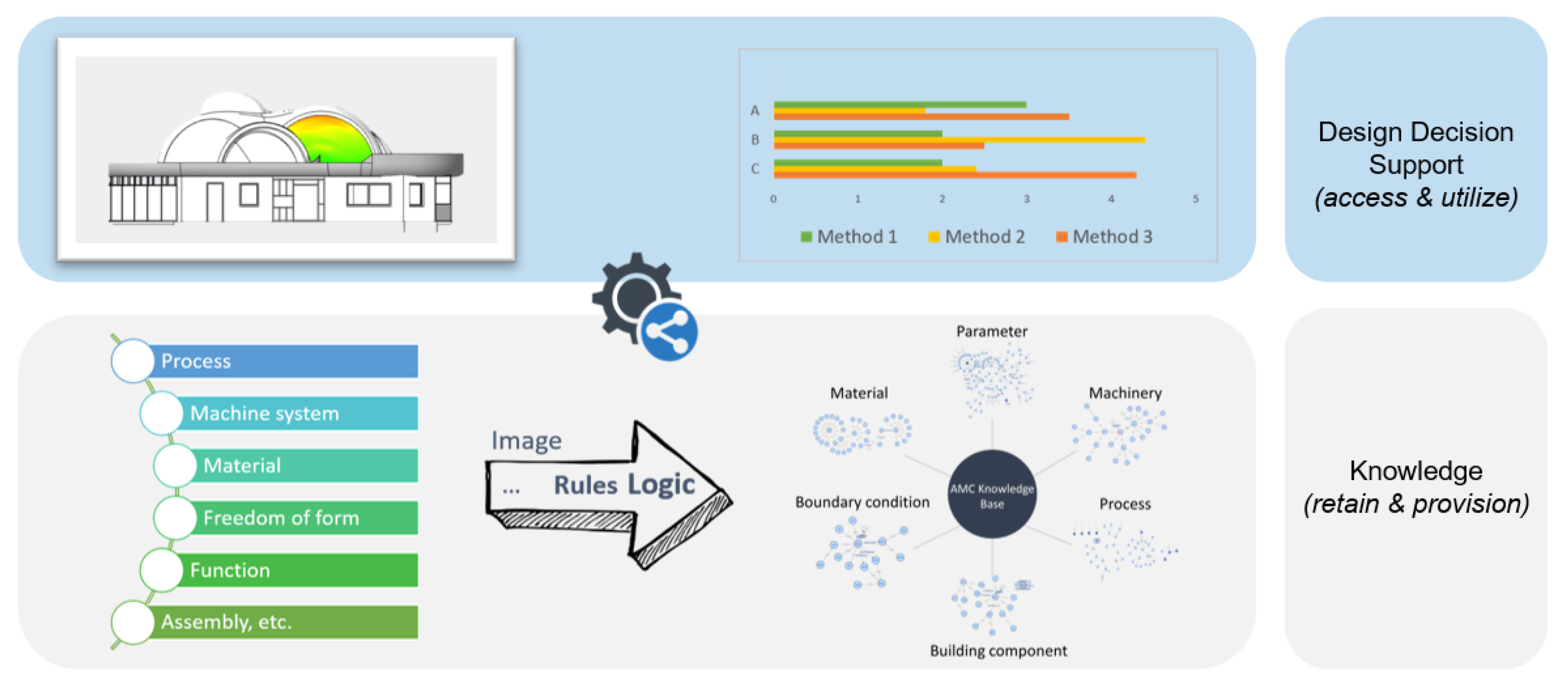
3. Knowledge-Driven Decision Support with a Feedback Mechanism

To address the difficulty in choosing the most suitable AM methods for architectural design, we position both formal knowledge and a multi-disciplinary feedback mechanism within the paradigm of design decision support. The underpinning belief for this methodology is that the combinatorial use of formal domain knowledge and machine-understandable communication protocols can effectively reduce the expensive design iterations by proactively considering AM-related constraints and formulating cross-domain communications (see Figure 2). Different research efforts have provided a practically defensible foundation to introduce knowledge formalization, claiming the benefits of fostering manufacturable design and increasing overall productivity for off-site production [22,55]. Additionally, protocol-based, cross-disciplinary communications are deemed contributors to decision-making under multiple design variants [20].
If we apply these to future additive construction projects, the profits will be multi-factorial. A shared knowledge base encoding experts’ knowledge of different AM methods provides a reliable reference for architects, engineers, and contractors during architectural design, numerical simulation and planning stages. Adopting minimized and tailored communication protocols relieves the urgent problem of cross-border collaborations stressed in [37], incorporating different experts from AM material, printers’ mechanics, regulatory approval, etc., into an interoperable framework. The following content in this chapter addresses knowledge-driven decision support with formalized AM knowledge and a tailored feedback mechanism; it then demonstrates a use case integrating the two approaches. To clarify, this paper focuses on explicit knowledge, which is formalizable, rather than its counterpart, tacit knowledge, which is hard to articulate and is usually captured using machine learning techniques [56,57]. Scoped in the TRR277 project, the explicit domain knowledge is formalized and named the AMC knowledge base in the following sections.

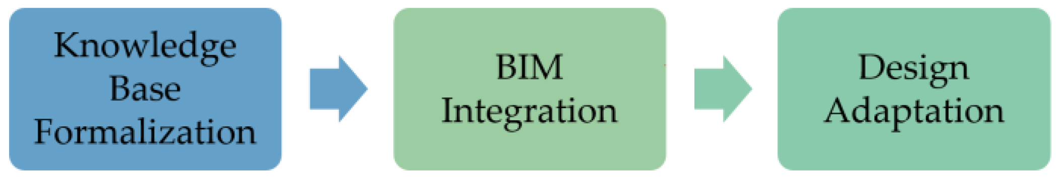
3.1. AMC Knowledge Formalization and BIM Integration: Principle and Methodology

In general, three major objectives need to be met to establish a knowledge-driven decision support system for the BIM-based design (Figure 3). As a basis for the system, it is necessary to formalize an AMC knowledge base where ontology and rules are utilized to represent domain knowledge. Next, the knowledge base is integrated and readily used for the BIM-based design—to this, available algorithms and tools are embedded to support geometry analysis and semantics retrieval, as well as an automatic inference from newly given facts. Last but not least, visual and textural feedback should be presented on the BIM-based design to support design adaptations.
Before entering the ontology-building processes, it is indispensable to resolve two questions: “what is the methodology deployed to build the ontology?” and “what is the principle of reuse during the implementation of ontology?”.
Over the decades of research, several ontology-building methodologies have been proposed, while common activities comprise specification, knowledge acquisition, conceptualization, formalization, and validation [58,59,60]. Attributed to the ever-increasing implementations and complex nature of additive construction, domain experts’ knowledge could not be complete or thoroughly comprehended by ontology engineers in a single round. Concluding from that, it is appropriate to follow the lifecycle of an evolving prototype [60]: after each involved activity, if the ontology does satisfy the required evaluation criteria, the previous activity should be repeated to improve the prototype. Furthermore, knowledge acquisition should be performed throughout the whole life cycle in order to capture new or more accurate knowledge to enhance the quality of the ontologies.
To answer the second question, we seek open-accessed ontologies (partially) reusable for additive construction, and best practices can be followed to develop a well-grounded AMC ontology. In the manufacturing domain, many have formalized AM-specific ontologies with the principle of restrictive design for additive manufacturing (DfAM), analyzing the manufacturability of designed parts [61,62,63]. These ontologies provide solid references for the application of a restrictive design for additive manufacturing (DfAM). However, due to the distinctive nature of additive construction, the reuse of these application-level ontologies requires adaptations, including concept re-definition and changes in application scenarios [64]. As to the construction domain, the ifcOWL ontology as an ontological version of the IFC data schema has been adopted for researchers to build up the knowledge bases [55,65]. Meanwhile, Slepicka and Borrmann proposed a set of fabrication information models (FIMs) for material, process, and machinery aspects in additive construction [12]. Nevertheless, ifcOWL falls short in describing resources and capabilities [66], it requires simplifications and clarifications to be properly used for instance graphs and domain ontologies [67,68]. Having a consensus view of ontology interoperability, many have used upper ontologies for domain ontology alignment or as design patterns to create new ontologies. Ocker et al. built an intermediate engineering ontology (IEO) bridging different manufacturing domain ontologies with the upper ontology of DOLCE [69]. The IEEE community makes efforts to align its existing ontologies [70,71] to the DOLCE+DnS Ultralite (DUL). The BFO has been acknowledged in the ISO standard to support information exchange and provide a well-founded computational ground for the development of various domain ontologies, including the industrial ontologies foundry (IOF) ontology [72] for the manufacturing industry and the aforementioned DiCon ontologies for the AEC domain. Currently, both IOF and DiCon still undergo development and lack axioms to support the decision-making of AM-oriented architectural design on which various constraints and requirements may apply.
To conclude, the AMC knowledge base is oriented to early design decision support; it should thus be built from adapting and assimilating feature-based ontologies for manufacturability justification. Practically, it needs to consider legal norms and enforce them as design constraints. Further, the AMC knowledge base should be aligned to an upper ontology in order to organize the heterogeneous knowledge and information over the scope of AMC.

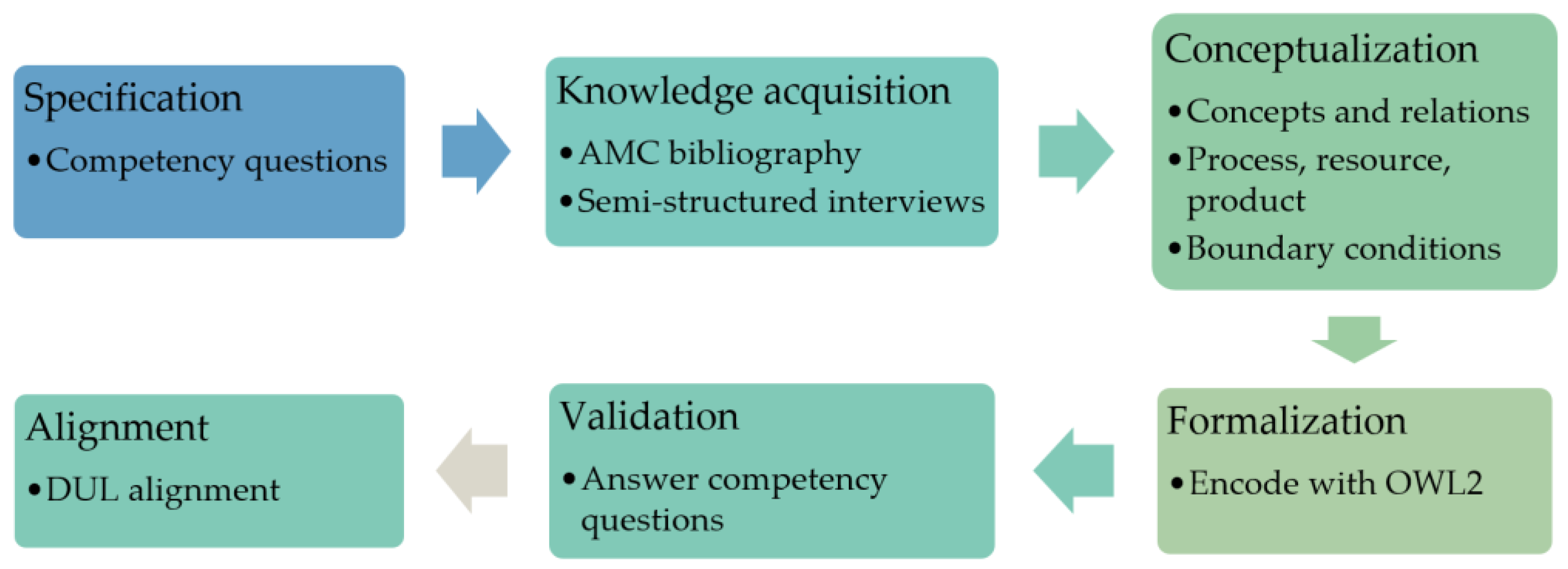
3.2. Ontology Building Processes

To proceed with the building of the AMC knowledge base, the activities mentioned in Section 3.1 are implemented (Figure 4). The following contents in this section will elaborate on each activity in more detail.

3.2.1. Specification

At the very beginning of the specification process, it is necessary to clarify that the knowledge base to be formalized is on the application level for design deci-sion support, hence, it does not aim to provide semantically sound or complete definitions for each of its terms, e.g., regarding the most general concept of the AMC process, it is not able to answer, “what is an additive manufacturing process?”, from the logical point of view. Rather, it should compose groups of operative resources, product categories, essential rules, AM methods’ taxonomies, and descriptive activities such that the following competency questions (CQs) could be answered (Table 1).

3.2.2. Knowledge Acquisition

According to Mendonça et al. [73], knowledge acquisition activities involve extraction, elicitation, validation, and refinement. Departing from the Natural Language Processing (NLP)-based term extraction process adopted by [73], the authors have studied a set of peer-reviewed papers for AMC methods, thus elucidating technical terms that are influential to architectural de-sign (e.g., cycle time and open time). An informal questionnaire was drafted as the protocol for semi-structured interviews. Experts in different AMC methods were asked to fill in the questionnaire and complement missing points during the interview session. Eventually, the filled-in questionnaire and relevant bibliography became the basis of the conceptualization process.

3.2.3. Conceptualization

The conceptualization phase figures out the required concepts for AMC and clarifies their relations. To reveal the various constraints imposed by building codes, manufacturing methods, transport regulations, etc., the plan entity was conceptualized (Figure 5). Regarding additive construction, the planning workflow should proactively consider the legal norms (norm entity) and follow suitable manufacturing, assembly, and transport methods. Following the process, product, and resource (PPR) model widely used in the manufacturing domain, AM processes (process entity), building components (product entity), material (resource entity), labor (resource entity), and machine systems (resource entity) are conceptualized and related. To disambiguate the meaning of processes and methods, this work treats process entity as a catchall term without obligation to define involving tasks, agents, or duties, whereas method entity describes a sequence of tasks, required resources, and products as well as a catalog of parameters for quantity, cost, operation time, etc., such that the planning workflow can evaluate, specify and arrange suitable methods for additive construction. The so-called method is more descriptive than precise; hence, it is not mandatory to assign exact values to the defined parameters but these can be deferred to the planning stage. Note that legal norms can be optional in some test projects; this also settles disputes if some flexible and powerful methods easily adapt to and meet the regulatory requirement.
At the component scale, the requirements correspond to the architect’s design intent in terms of the material, geometry, and function of the building components, which are integrated into the BIM-based design. This breakdown facilitates the logic-based evaluation and planning but postulates a well-structured description of the information’s accuracy. To this end, Abualdenien and Borrmann have studied a multi-LOD data model to quantify fuzziness [46]; however, assimilating this concept in the AMC ontology will introduce the fuzzy extension of OWL DL [74] for inferencing capability and is beyond the scope of this work. In the current stage, building components’ semantic and geometry information, once given in the ontology, is deemed certain. Nevertheless, missing information is permissible due to the open-world assumption, and one can resort to the feedback mechanism for adaptive detailing (Section 3.4). To continue, the thermal insulation function of building components can be quantitatively represented as U-values, whereas the load-bearing function is usually binary, contextualized, and tied with both building materials and components’ forms. For simplicity, the AMC ontology parameterizes the load-bearing function with the dichotomy—load-bearing or not, and delegates this function requirement to material properties that are quantifiable.
Although AM methods have brought more geometry freedom, they are constrained to certain kinds of geometry features due to the additive principle. Meanwhile, different AM methods present diverse performances in functional aspects. In this regard, the so-called boundary conditions are special parameters defining the limit of AM methods regarding printed components’ geometry and functions. More specifically, manufacturing features including overhang, cavity, curvature, bounding box, etc., and printed specimens’ mechanical, sound, and thermal properties are quantitatively or qualitatively identified, aggregated to find extremes and set as boundary conditions. Norms also set constraints on the involved methods and might in turn impact the architectural design. With norms considered in the planning stage, disconformities within the design can be informed in the early stages when design adaptations are still cost-effective. For instance, the road freight transport standard defines the item’s maximum transportable dimension, which restricts the size of building components and demands rational decompositions.
Therefore, a requirement-constraint pattern is devised (Figure 6). Requirements are, in general, the material type, material properties, functions, and manufacturing features of a building component. As the counterpart, constraints are inherited from the uptaken norms, and manufacturing and transport methods can be intuitively formulated under the NormParameter and BoundaryConditionParameter entities. Here we arrange the NormParameter in parallel with the BoundaryConditionParameter which is associated with methods; by doing so, constraints can be clearly attributed to either legal norms or methods used for additive construction. During the evaluation processes, these restrictive parameters will be applied to building components through the isManufacturedWith property, such that the parameterized material and functional expectations, manufacturability, as well as norm compliances can be verified by simple rules.

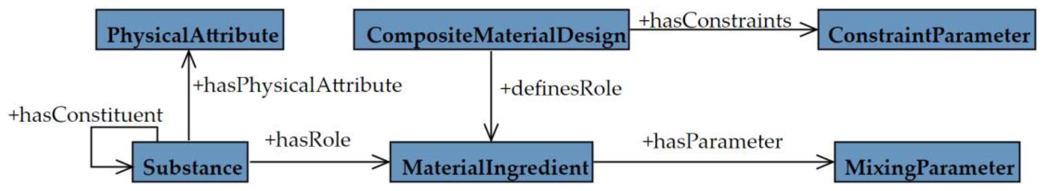
3.2.4. Formalization

Considering the prior determination of description logic (OWL2 DL) for building the ontology, concepts and relations derived from the previous step are encoded as the AMC ontology partially illustrated in Figure 7. The current ontology distinguishes between as-planned and as-printed building components, and the function boundary conditions are elicited from the technical reports conducting tests on the as-printed ones. Such a distinction coincides with the reality that discrepancies do exist between designed and built artifacts, and potentially leaves the space to preserve both in the same data schema for rooting the causes. In Figure 7, the as-planned entities such as BuildingComponent and BuildingMaterial are located in the upper part as requirements; and the as-printed entities of PrintedBuildingComponent and PrintedMaterial are located in the lower part as constraints. The entity regarding material mix design is hidden in the view as it intertwines requirements and constraints.
As illustrated in Figure 8a, the AdditiveManufacturingMethod entity’s intentionality is narrowed by assigning relevant axioms to its superclass. Cardinalities in the conceptual model are transcripted into the property cardinality restrictions in OWL2. In Manchester OWL syntax, “1..*” becomes “some”, and “0,1” becomes “max 1”. The same approach applies to other entities relating to each other with object properties. In Figure 8b, additive construction tasks regarding prefabrication (still in the component scale) are given. With the precedes and hasPart object properties (see Figure 5), these tasks can be sequenced and subdivided. Moreover, each task can be assigned a time period indicating the expected execution time, with resources (resource entity) allocated during the execution. As such, the planning and scheduling of the additive construction can be facilitated.

3.2.5. Validation

In this step, the competency questions listed in Table 1 are analyzed, and subsequently answered with SPARQL queries to prove the correctness of the formalized AMC ontology. CQ1 to CQ8 address the descriptive information about AMC methods including capabilities and constraints, while CQ9 to CQ12 delegate the requirements of designed building components. CQ13 extends the scope of constraints affecting the architectural design. Among these, CQ1 and CQ9 are answered by querying the entities’ direct types. If necessary, the hierarchy of types can also be provided. Q1 shows an example to query the taxonomy of AMC methods from one of its instances, and it can be adapted to answer the CQ9 with substitutions; hence, “METHOD_INST”, “AMC_KB” and “AdditiveManufacturingMethod” should be substituted by specific URIs for method individuals, AMC ontology, and the uppermost class in the hierarchy, respectively:
SELECT DISTINCT ?type
WHERE {<METHOD_INST> rdf:type/rdfs:subClassOf* ?type.
?type rdfs:subClassOf* AMC_KB:AdditiveManufacturingMethod}
If the sequence of executions is interested, CQ2 requires some extra axioms to be answered under the DL profile. Two typical approaches are: introducing a new class to represent ordered collections (elaborated in [49]), or specially creating a subclass to activate the executions. This work opts for the second approach, treats the class SetupTask as the activation task and answers the CQ2 with two queries (Q2 and Q3).
SELECT ?task ?laterTask
WHERE {<METHOD_INST> AMC_KB:sequencesTask ?task.
?task AMC_KB:precedes ?laterTask}
SELECT ?firstTask
WHERE {<METHOD_INST> AMC_KB:sequencesTask ?firstTask.
?firstTask a AMC_KB:SetupTask}
On the other hand, CQ3, CQ5, CQ7, and CQ11 are answered by retrieving the type of entity relating to the given AMC method or building component by following the pattern illustrated in the Q4 which solves the CQ7. Substitutions are required for CQ3, CQ5, and CQ11 with object properties of printMaterial, usesMachineSystem, and hasMaterial.
SELECT DISTINCT ?geometryFeature ?type
WHERE {<METHOD_INST> PREFIX:isLimitedIn ?geometryFeature.
?geometryFeature a ?type.
?type a owl:Class}
The CQ4, CQ6, CQ8, and CQ12 call the data property values regarding parameters for the entities retrieved using Q4; i.e., CQ3, CQ5, CQ7, and CQ11 must be answered beforehand. The common procedure is to obtain the related instance and its object property, then retrieve the data property values from that object property. Here we take CQ8 as an example, assuming the set of manufacturing features important to the AMC methods have already been addressed by Q4. The query Q5 shows the important answer to CQ8—the overhang feature is taken as an example.
SELECT ?FeatureValue
WHERE {<METHOD_INST> AMC_KB:hasBoundaryCondition ?overhangBDC.
?overhangBDC a AMC_KB:OverhangBoundaryCondition.
?overhangBDC AMC_KB:hasDoubleValue ?FeatureValue}
CQ10 is a synthesized question to both the types of manufacturing features and their values that inhere to a building component. As manufacturing features’ parameters differ in data structures, the following query accesses the parameters merely for illustration.
SELECT ?featureParam ?feature
WHERE {<COMPONENT> AMC_KB:hasManufacturingFeature ? feature.
?feature AMC_KB:isParameterizedBy ?featureParam}
CQ13 then considers holistically other types of constraints during construction planning. In the current ontology, there needs to be a planning instance that considers some legal norm, and Q7 shows how to assign the regulatory constraints to the planning instance.
SELECT ?norm ?normParameter
WHERE {<PLAN_INST> AMC_KB:considersNorm ?norm.
?norm AMC_KB:setConstraints ?normParameter}
On top of the ontologies, rules are made using the rule-making language of SWRL. In theory, SWRL extends the expressivity of OWL2 DL [75]; in practice, rules are made to bind manufacturing and planning constraints to design intent such that inferences can be made regarding manufacturability, material conformity, logistics, etc. As Li and Petzold have already addressed this rule-making problem [42,64], this work will not go into detail again.

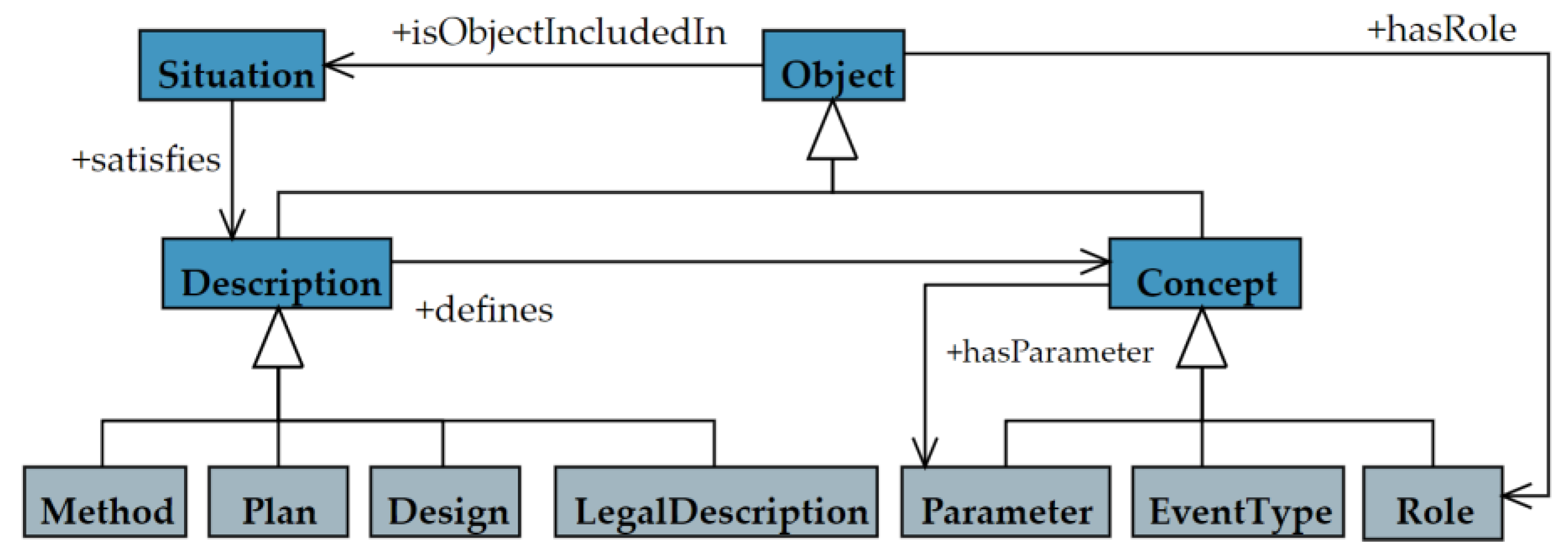
3.2.6. Alignment to DUL Upper Ontology

Until now, the formalized AMC ontology has been well qualified as an application ontology, but a potential risk is that a thorough understanding of intertwining relations and entities is still missing, thus hindering the ontology‘s extensibility. The DUL upper ontology is simplified from the DOLCE Lite Plus and is enriched with extensions for information objects, plans, systems, legal, and lexical and semiotic domains [76]. It provides a principle to separate a set of assertions (Situation entities) from their interpretations in the non-physical contexts (Description entities); hence, the facts that already exist are treated differently from their conception. Thinking on the formalized AMC ontology, the planning of additive construction, different AMC methods, norms, possibly the material specification, etc., can be well aligned to the subclasses of the Description entity. Meanwhile, the parameters, tasks, and the PPR model (modeled as Role entities) can be categorized as Concept entities. Specific variants under the same AMC method can be observed as individuals of the Situation entity that satisfy (satisfies object property) their uniform Description (Figure 9).
Following the role-based modeling pattern endowed by DUL, the AMC ontology can neatly describe the concrete specification consistently. As shown in Figure 10, the material design as a type of Description defines ingredient roles (aggregates, binder, etc.) which are parameterized with mixing parameters, and the substances (e.g., some sand) take the roles in such a description. The constraint parameters can be assigned to the material specification, while the characteristics of the substances are valued via their attributes.

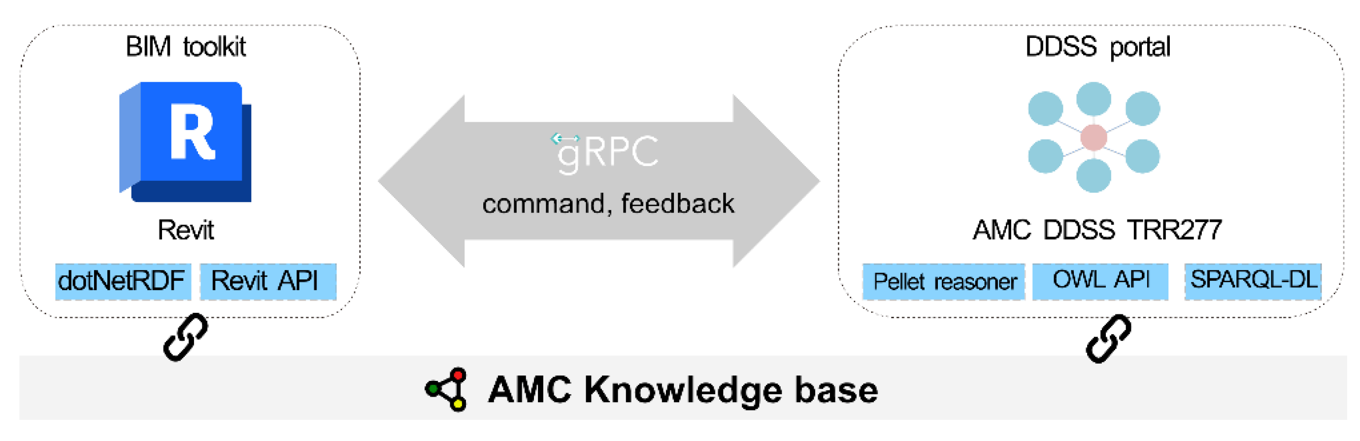
3.3. BIM Integration and Intuition of Design Adaptation

As proof of concept, we followed the technical framework raised by [42] and implemented a prototype of the knowledge-driven DDSS. As shown in Figure 11, the AMC ontology is made available for the BIM authoring tool (Revit) via a plugin (BIM toolkit), while the inference service is provided by another standard-alone software (DDSS portal). Building components’ geometry and semantic information can be retrieved from a BIM model by relevant APIs and feature extraction algorithms integrated into the BIM toolkit. Afterwards, information about features and semantics is transmitted to the portal through the remote procedure call (RPC). The inference capability of the DDSS portal is enabled by an embedded reasoner working on a local replica of the AMC knowledge base; hence, OWL and SPARQL APIs are responsible for creating, updating, reading, and deleting actions before and after the inference-making.
Figure 12 illustrates the prototype of the DDSS portal. The transmitted information is presented regarding the detected manufacturing features and semantics (Figure 12a). Internally, the information is also created or updated in the local copy of the knowledge base using OWL API. Material properties, machine system information, etc. of AM methods are listed such that the architects are able to compare and filter based on the requirements of building components. The applicability of an AM method is verified by the reasoner according to the SWRL rules and is relayed to the architects (Figure 12b). In case any requirement is not met by the AM method, the architects can set commands to the BIM toolkit for visualization.
Based on the type of requirement and inference results, the BIM toolkit automatically presents suitable visualizations. As illustrated in Figure 13, a parametric Revit “family” representing the bounding box of the machine system’s workspace is aligned to the evaluated building component. As the building component’s oriented bounding box (OBB) has been computed during the feature extraction phase, aligning the Revit family to this freeform geometry turns into trivial positioning and orientation from one cubic box to another via Revit API. It seems that, with these parametric Revit families available during the design stages, architects will be supported to generate a design that adapts to the constraints of manufacturing dimensions. However, this cannot be easily achieved completely by architects; for instance, partitioning a large wall into pieces will require extra structural analysis for the building and an overview of AM methods. Therefore, we conclude that the current knowledge-driven decision support could assist architects in finding potential problems in the early stages, but solving the problems still demands technical expertise in other fields.

3.4. Feedback Mechanism for AMC

Previous sections have elaborated on the knowledge-driven DDSS, especially the AMC knowledge base. The following part will introduce a feedback mechanism for communication between architects and engineers, and subsequently demonstrate a use case in AMC.

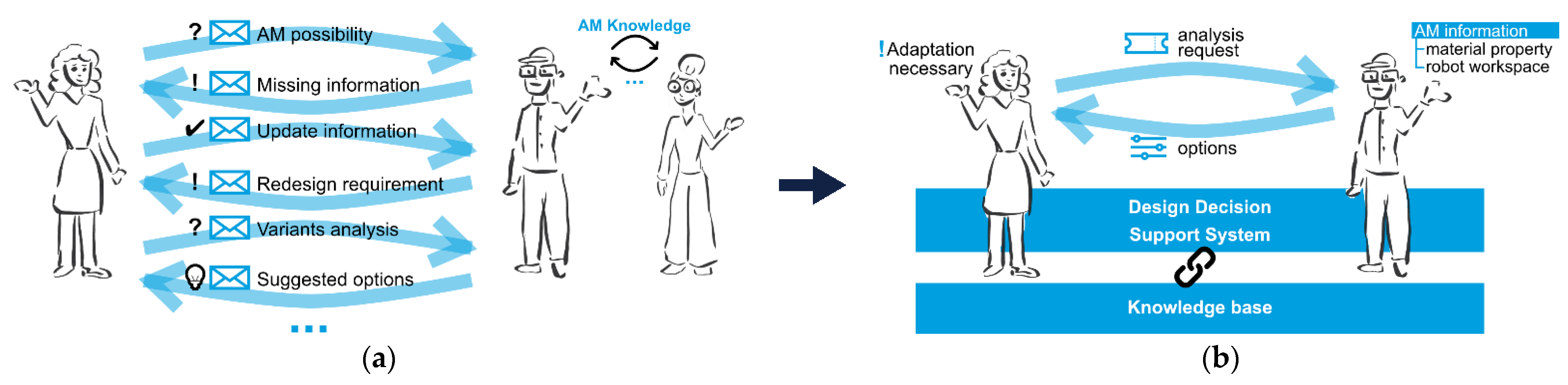
3.4.1. Introduction of the Feedback Mechanism

In the early design stages, the BIM model is still immature and could not be qualified for numerical analysis and performance assessment. Based on a CDE where BIM models are stored and collaborated on by architects and domain experts, architects can communicate with the experts and receive their feedback for design detailing and decision support. To improve efficiency and traceability throughout communications, Zahedi and Petzold [48] proposed the use of a ticketing system with a feedback mechanism. Similar to any other ticketing system, this system sets the priority for each ticket and traces the responses from domain experts. The communication can be initiated by sending requests or tasks within a ticket; afterwards, experts’ responses are embedded in the feedback mechanism. This mechanism aims to provide a machine-readable communication protocol to adaptively detail the design and evaluate possible design variants. In general, three types of feedback are provided:
  • Missing details in the design model which are critical for analysis
  • Suggested options that meet the design requirements or fulfill the shortcomings
  • Related results of simulations or analysis
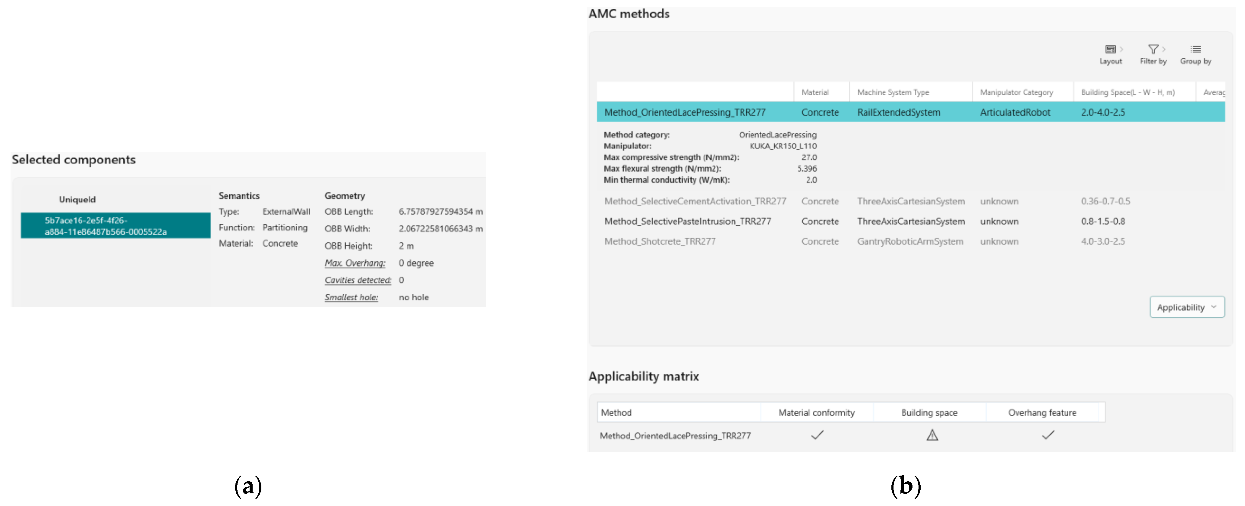
To meet the varying needs under different scenarios, the feedback function is structured with different arguments as follows:
Feedback (actionType, optionGroupID, GUID, schemaX, objectID, propertyID, value)
The first argument as actionType represents a use case for the feedback function. The possible value ranges are: missingObject, missingObjectProperty, createNewObject, deleteObject, and updateObjectProperty. Intuitively, missingObject handles the general use case where some building components are (suspiciously) missing from the engineers’ point of view, such as missing opening(s) on the side of a living room near the balcony—which impacts the analysis result of energy consumption. The missingObjectProperty refers to the incomplete properties or semantic information that needs to be filled out by the architects—a typical example is the strength (class) of the building material. On the other hand, createNewObject means a new component to a newly created building component (possibly as part of options) by a domain expert (consultant), depending on the architect’s acceptance or objection. The newly created component has a unique GUID that will be used to reference the object. Together with the newly created ones, some existing objects may be deleted. DeleteObject could also be assigned when engineers think some objects introduce significant side effects that are hard to deal with. UpdateObjectProperty is used to indicate to the architect of the suggested property value(s) as option(s).
The next argument, optionGroupID, helps to group multiple suggestions and is optional, i.e., advised details can be individually treated or grouped together as batch information. This brings efficiency in accepting or rejecting the modifications in a package. When properly arranged, this will also help to keep the consistency in the BIM model because building components are always topologically and functionally interdependent. The argument of GUID holds the global identification IDs of the building components over the CDE and inheres to them—that is, if the building components cease to exist, their GUID parameters also vanish. If the actionType in the feedback function is missingObject, then this argument (GUID) will be the unique ID of the hosting build component. As to the example where the openings are absent, this GUID might belong to the wall adjacent to the balcony. Similarly, for missingObjectProperty and updateObjectProperty, the GUID applies to the existing building component which lacks specific object properties, while createNewObject action sets a GUID on the temporary newly created object advised by the domain expert to the architect. Finally, when the actionType is deleteObject, this GUID refers to the build component that the domain expert suggests deleting.
For each type of analysis, there is a list of critical information that has to be provided. The schemaX argument then plays as a dictionary for analysis of specific information exchange between architects and domain experts; for instance, life cycle assessment (LCA) requires the input value of window-to-wall ratio, u-value, wall thickness, etc., which are classified as propertyID for different types of building components (objectTypeID). It follows the so-called adaptive LOD model (aLODx) from the work of [48], but relaxes the specification of the multi-LOD data model in the meantime, i.e., this schemaX is less structured and could be adjusted with the advances of AMC. Further details on the feedback mechanism and how to use it are discussed in the works of [48].

3.4.2. Use Case

We continue with the scenario prescribed in Section 3.3: when an architect realizes the problem of oversized building components, he or she could initialize communication with a structural engineer who is responsible for structural analysis and code compliance. At this stage, a ticket will be sent to the engineer, requesting the decomposition of the wall into manufacturable pieces for an AM method. On the basis of some understanding of AM technology, the architects could be inclined to deploy some specific AM method(s) already and embed this information in the ticket.
Upon receiving this request, the structural engineer should have an overview of the design for the building (or a zone with other building components connected), information on AM methods, and applicable standards for regulatory approval. The engineer is able to retrieve the material information from the given AM method noted in the ticket: whether the concrete is reinforced, the density, thermal conductivity, etc.
With adequate information at hand, the engineer proposes two options of decomposition, essentially, a two-way vertical decomposition with one of the parts for load-bearing, or a three-way vertical decomposition with both sides as load-bearing components (Figure 14). The rationale behind this is that the engineer finds out that the AM method is able to integrate reinforcement, and subsequently suggests the two-way option following the code of concrete structure, as well as the three-way option analog to masonry construction. These options are encapsulated in the feedback function as a response to the architect. Finally, the architects will choose one of the options by evaluating practical criteria such as cost, construction time, etc. On this basis, more complex scenarios can be created; for instance: an AM expert knowing the impacts of cycle time on the mechanical performance would stress the minimum dimension of a building component to assure stability during building up. To verify the feasibility of decomposing options, the structural engineer can also initiate a ticket and send it to the AM expert, who will have access to the process parameters stored in the knowledge base for further evaluation.
From the depicted case above, we noticed a smooth design workflow assisted by the knowledge base and feedback mechanism. While the knowledge base enables the early recognition of conflicts between design and manufacturing, the feedback mechanism bridges the subsequent design development and domain-specific expertise. Both techniques are able to address the problems (semi-)automatically. It can be concluded that the methodology of synergizing formal domain knowledge and feedback mechanism is forward-looking, and we look forward to its development in additive construction.

4. Discussion

This paper addresses the explicit dimension of AMC knowledge and brings it to the early decision of proper manufacturing methods. Compared to previous efforts (e.g., [61,62,63]) in formalizing AM knowledge, this work has additionally introduced the terms for planning stages when regulations could further restrict the design and preliminarily align the ontology to DUL, such that the multidisciplinary knowledge in AMC can be modeled with consistency. Integrating the description and situation plugin (see Section 3.2.6) [77,78], DUL ontology with its extensions can represent contexts (e.g., laws, plans, assessments) and their executions which are less formal or missing in other ontologies, even in comprehensive ones such as [52,72] and similar; however, terms of “capability” and “function” useful in the engineering domain are not explicitly formalized in the DUL ontology but in BFO (and its proposal) [79]. The AMC ontology would have to seek appropriate tradeoffs during the alignment and even mapping stages after gaining insights into the differences between DOLCE and BFO ontologies [80]. With this in mind, we are temporarily inclined to DUL but would look into other possibilities in the future.
In the case of manufacturability evaluation, the major limitation of our approach lies in the computational complexity of extracting manufacturing features from any geometry object. This is an inherent problem for knowledge-based manufacturability determination and has also been discussed by Mayerhofer et al. [61]. With the increasing capability of computational resources, machine learning (ML) methods have gained attraction in many domains and are unsurprisingly applied in the AM. For instance, Zhang et al. utilized the convolutional neural network (CNN) method to evaluate the designed parts’ manufacturability and presented acceptable accuracy [81]. Nickchen et al. further evaluated the possibilities of ML in the AM process chain for 3D component recognition and manufacturing cost estimation [82]. While acknowledging the potentials of ML in solving complex problems in AM-oriented design, logic-based reasoning holds its position in areas where human’s knowledge can be explicitly expressed (the counterpart of tacit knowledge [56]) and heterogenous information is organized. As to AMC, explicit design rules can apply to the early-staged design, and multiple aspects of additive construction can be coordinated using the AMC ontology. In fact, researchers have already been investigating the synergy of ontologies and ML methods and predicted it as a promising direction [83,84]. Therefore, we can improve the proposed logic-based method on the one hand and look forward to the integration of ML methods for enhanced decision support on the other hand.
Another contribution of the work is to propose the joint use of formal knowledge and a feedback mechanism for decision support—which, to the authors’ knowledge, has not been well studied for additive construction. The proposed methodology does not much stress the formal knowledge for which the expressiveness and computation complexity are often at odds; further, it complies with the common practice in AEC where different experts cooperate on the same project and has the potential to enhance the negotiations which are usually desultory and inconsistent.

5. Conclusions

AM technology and BIM are considered to be the driving force for the revolution in AEC. To solve the problem of missing knowledge at the early stage of architectural design, this work proposes the use of formal knowledge and communication protocols for BIM-based design decision support. In the scope of AMC, we elaborated on these two factors by describing the knowledge formalization and integration procedures, as well as feedback mechanisms that emphasize the importance of interprofessional negotiation. This work focuses more on the knowledge formalization activities and envisions the alignment to the DUL upper ontology, aiming to provide a solid foundation for the current logic-based reasoning.
Nevertheless, the proposed methodology needs to be strengthened in the future from the following aspects:
  • The alignment of the current AMC ontology to DUL needs to proceed and must consider important terms of Function, ManufacturingFeature (even Feature), BoundaryCondition, etc. Some modifications may be made to the current AMC ontology, and DUL will be referenced as a design pattern once inconsistencies are found during the alignment process.
  • The aligned ontology could be used to organize heterogeneous information including digital resources, linguistics, robot mechanics, etc.
  • Efficient feature extraction algorithms should be explored in order to take the flexible slicing directions and the robot’s high DOF into account.
  • Explanation functionality for the inference results would greatly improve the comprehensibility of the DDSS and should be further developed.
  • More task-specific communication schemas must be identified with domain experts familiar with conventional construction methods and AM optimization. Last but not least, a framework incorporating the knowledge base and feedback mechanisms should be implemented in the future such that the architects and engineers are engaged in a smooth and productive design workflow.

Author Contributions

Conceptualization, C.L., A.Z. and F.P.; methodology, C.L., A.Z. and F.P.; software, C.L.; validation, C.L.; formal analysis, C.L.; investigation, C.L.; writing—original draft preparation, C.L.; writing—review and editing, C.L. and A.Z.; supervision, F.P.; project administration, F.P.; funding acquisition, F.P. All authors have read and agreed to the published version of the manuscript.

Funding

This research was funded by the Deutsche Forschungsgemeinschaft (DFG, German Research Foundation)—Project Number 414265976—TRR 277. The APC was funded by Deutsche Forschungsgemeinschaft (DFG, German Research Foundation)—Project Number 414265976—TRR 277.

Data Availability Statement

Not applicable.

Acknowledgments

We also gratefully acknowledge the support of the DFG for funding the project under grant FOR 2363.

Conflicts of Interest

The authors declare no conflict of interest.

References

  1. Santamouris, M.; Vasilakopoulou, K. Present and future energy consumption of buildings: Challenges and opportunities towards decarbonisation. e-Prime-Adv. Electr. Eng. Electron. Energy 2021, 1, 100002. [Google Scholar] [CrossRef]
  2. Ford, S.; Despeisse, M. Additive manufacturing and sustainability: An exploratory study of the advantages and challenges. J. Clean. Prod. 2016, 137, 1573–1587. [Google Scholar] [CrossRef]
  3. Arifin, N.A.M.; Saman, M.Z.M.; Sharif, S.; Ngadiman, N.H.A. Sustainability Implications of Additive Manufacturing; Springer: Singapore, 2022. [Google Scholar]
  4. Peng, T.; Kellens, K.; Tang, R.; Chen, C.; Chen, G. Sustainability of additive manufacturing: An overview on its energy demand and environmental impact. Addit. Manuf. 2018, 21, 694–704. [Google Scholar] [CrossRef]
  5. 3D Printing. Available online: https://d-shape.com/3d-printing/ (accessed on 3 April 2022).
  6. Kloft, H.; Krauss, H.-W.; Hack, N.; Herrmann, E.; Neudecker, S.; Varady, P.A.; Lowke, D. Influence of process parameters on the interlayer bond strength of concrete elements additive manufactured by Shotcrete 3D Printing (SC3DP). Cem. Concr. Res. 2020, 134, 106078. [Google Scholar] [CrossRef]
  7. Gosselin, C.; Duballet, R.; Roux, P.; Gaudillière, N.; Dirrenberger, J.; Morel, P. Large-scale 3D printing of ultra-high performance concrete—A new processing route for architects and builders. Mater. Des. 2016, 100, 102–109. [Google Scholar] [CrossRef] [Green Version]
  8. Labonnote, N.; Rønnquist, A.; Manum, B.; Rüther, P. Additive construction: State-of-the-art, challenges and opportunities. Autom. Constr. 2016, 72, 347–366. [Google Scholar] [CrossRef]
  9. Boton, C.; Rivest, L.; Ghnaya, O.; Chouchen, M. What is at the Root of Construction 4.0: A Systematic Review of the Recent Research Effort. Arch. Comput. Methods Eng. 2021, 28, 2331–2350. [Google Scholar] [CrossRef]
  10. Paolini, A.; Kollmannsberger, S.; Rank, E. Additive manufacturing in construction: A review on processes, applications, and digital planning methods. Addit. Manuf. 2019, 30, 100894. [Google Scholar] [CrossRef]
  11. Industry Foundation Classes (IFC)–buildingSMART Technical. Available online: https://technical.buildingsmart.org/standards/ifc/ (accessed on 6 April 2022).
  12. Slepicka, M.; Vilgertshofer, S.; Borrmann, A. Fabrication information modeling: Interfacing building information modeling with digital fabrication. Constr. Robot. 2022, 6, 87–99. [Google Scholar] [CrossRef]
  13. Davtalab, O.; Kazemian, A.; Khoshnevis, B. Perspectives on a BIM-integrated software platform for robotic construction through Contour Crafting. Autom. Constr. 2018, 89, 13–23. [Google Scholar] [CrossRef]
  14. Smarsly, K.; Peralta, P.; Luckey, D.; Heine, S.; Ludwig, H.M. BIM-Based Concrete Printing. Lect. Notes Civ. Eng. 2021, 98, 992–1002. [Google Scholar] [CrossRef]
  15. Borrmann, A.; König, M.; Koch, C.; Beetz, J. (Eds.) Building Information Modeling: Technology Foundations and Industry Practice; Springer: Cham, Switzerland, 2018; pp. 235–314. [Google Scholar]
  16. Nowak, P.; Ksiązek, M.; Draps, M.; Zawistowski, J. Decision Making with Use of Building Information Modeling. Procedia Eng. 2016, 153, 519–526. [Google Scholar] [CrossRef] [Green Version]
  17. Tan, T.; Mills, G.; Papadonikolaki, E.; Liu, Z. Combining multi-criteria decision making (MCDM) methods with building information modelling (BIM): A review. Autom. Constr. 2021, 121, 103451. [Google Scholar] [CrossRef]
  18. Sacks, R.; Eastman, C.; Lee, G.; Teicholz, P. BIM Handbook; John Wiley & Sons: Hoboken, NJ, USA, 2018. [Google Scholar]
  19. Rezaee, R.; Brown, J.; Augenbroe, G.; Kim, J. Assessment of uncertainty and confidence in building design exploration. Artif. Intell. Eng. Des. Anal. Manuf. 2015, 29, 429–441. [Google Scholar] [CrossRef]
  20. Abualdenien, J.; Schneider-Marin, P.; Zahedi, A.; Harter, H.; Exner, H.; Steiner, D.; Singh, M.M.; Borrmann, A.; Lang, W.; Petzold, F.; et al. Consistent management and evaluation of building models in the early design stages. J. Inf. Technol. Constr. 2020, 25, 212–232. [Google Scholar] [CrossRef] [Green Version]
  21. An, S.; Martinez, P.; Al-Hussein, M.; Ahmad, R. BIM-based decision support system for automated manufacturability check of wood frame assemblies. Autom. Constr. 2020, 111, 103065. [Google Scholar] [CrossRef]
  22. Cao, J.; Vakaj, E.; Soman, R.K.; Hall, D.M. Ontology-based manufacturability analysis automation for industrialized construction. Autom. Constr. 2022, 139, 104277. [Google Scholar] [CrossRef]
  23. Buswell, R.A.; da Silva, W.L.; Bos, F.; Schipper, H.; Lowke, D.; Hack, N.; Kloft, H.; Mechtcherine, V.; Wangler, T.; Roussel, N. A process classification framework for defining and describing Digital Fabrication with Concrete. Cem. Concr. Res. 2020, 134, 106068. [Google Scholar] [CrossRef]
  24. Contour Crafting Corporation|Construction 3D Printing|California. Available online: https://www.contourcrafting.com/ (accessed on 30 September 2022).
  25. Lowke, D.; Dini, E.; Perrot, A.; Weger, D.; Gehlen, C.; Dillenburger, B. Particle-bed 3D printing in concrete construction–Possibilities and challenges. Cem. Concr. Res. 2018, 112, 50–65. [Google Scholar] [CrossRef]
  26. HiRes Concrete-dbt: 3D-Printed Formwork for the NEST HiLo. Available online: https://dbt.arch.ethz.ch/project/3d-printed-formwork-for-hires-concrete-slab/ (accessed on 27 September 2022).
  27. Endres, E.; Mehnert, J.; Hildebrand, L.; Schweiker, M.; Roswag-Klinge, E.; Knaack, U. State of the art and potentials of additive manufactured earth (AME). In Proceedings of the 9th PowerSKIN Conference, Munich, Germany, 9 April 2021; Auer, T., Knaack, U., Schneider, J., Eds.; TU Delft Open: Delft, The Netherlands; pp. 203–212. [Google Scholar]
  28. Buschmann, B.; Henke, K.; Talke, D.; Saile, B.; Asshoff, C.; Bunzel, F. Additive manufacturing of wood composite panels for individual layer fabrication (Ilf). Polymers 2021, 13, 3423. [Google Scholar] [CrossRef] [PubMed]
  29. Dielemans, G.; Dörfler, K. Mobile Additive Manufacturing: A robotic system for cooperative on-site construction. In Proceedings of the International Conference of Intelligent Robots and Systems (IROS), Workshop Robotic Fabrication: Sensing in Additive Construction, Prague, Czech Republic, 27 September–1 October 2021. [Google Scholar]
  30. Tan, Y.; Dahlenburg, M.; Kessler, S.; Fottner, J. Virtual Prototyping mit DEM zur Entwicklung eines Near-Nozzle-Mixing Verfahrens für den additiven 3D Betondruck für den Roboter Einsatz. In Proceedings of the 25. Fachtagung Schüttgutfördertechnik, Magdeburg, Germany, 22–23 September 2021. [Google Scholar]
  31. Hack, N.; Kloft, H. Shotcrete 3D Printing Technology for the Fabrication of Slender Fully Reinforced Freeform Concrete Elements with High Surface Quality: A Real-Scale Demonstrator. In Proceedings of the Second RILEM International Conference on Concrete and Digital Fabrication, online, 6–9 July 2020; Springer: Cham, Switzerland, 2020; Volume 28, pp. 1128–1137. [Google Scholar] [CrossRef]
  32. Lanwer, J.-P.; Weigel, H.; Baghdadi, A.; Empelmann, M.; Kloft, H. Jointing Principles in AMC—Part 1: Design and Preparation of Dry Joints. Appl. Sci. 2022, 12, 4138. [Google Scholar] [CrossRef]
  33. Matthäus, C.; Kofler, N.; Kränkel, T.; Weger, D.; Gehlen, C. Interlayer Reinforcement Combined with Fiber Reinforcement for Extruded Lightweight Mortar Elements. Materials 2020, 13, 4778. [Google Scholar] [CrossRef] [PubMed]
  34. Freund, N.; Dressler, I.; Lowke, D. Studying the Bond Properties of Vertical Integrated Short Reinforcement in the Shotcrete 3D Printing Process. In Second RILEM International Conference on Concrete and Digital Fabrication; Springer: Cham, Switzerland, 2020; Volume 28, pp. 612–621. [Google Scholar]
  35. de Witte, D.; de Klijn-Chevalerias, M.L.; Loonen, R.C.G.M.; Hensen, J.L.M.; Knaack, U.; Zimmermann, G. Convective concrete: Additive manufacturing to facilitate activation of thermal mass. J. Facade Des. Eng. 2017, 5, 107–117. [Google Scholar] [CrossRef]
  36. Dielemans, G.; Briels, D.; Jaugstetter, F.; Henke, K.; Dörfler, K. Additive Manufacturing of Thermally Enhanced Lightweight Concrete Wall Elements with Closed Cellular Structures. J. Facade Des. Eng. 2021, 9, 59–72. [Google Scholar] [CrossRef]
  37. Bos, F.; Menna, C.; Pradena, M.; Kreiger, E.; da Silva, W.L.; Rehman, A.; Weger, D.; Wolfs, R.; Zhang, Y.; Ferrara, L.; et al. The realities of additively manufactured concrete structures in practice. Cem. Concr. Res. 2022, 156, 106746. [Google Scholar] [CrossRef]
  38. Weger, D.; Gehlen, C.; Korte, W.; Meyer-Brötz, F.; Scheydt, J.; Stengel, T. Building rethought – 3D concrete printing in building practice. Constr. Robot. 2021, 5, 203–210. [Google Scholar] [CrossRef]
  39. Xu, W.; Huang, S.; Han, D.; Zhang, Z.; Gao, Y.; Feng, P.; Zhang, D. Toward automated construction: The design-to-printing workflow for a robotic in-situ 3D printed house. Case Stud. Constr. Mater. 2022, 17, e01442. [Google Scholar] [CrossRef]
  40. About AMC TRR 277–Additive Manufacturing in Construction–Additive Manufacturing in Construction (AMC) TRR277. Available online: https://amc-trr277.de/trr-277-mission/ (accessed on 22 September 2022).
  41. Li, C.; Petzold, F. Integrating Digital Design and Additive Manufacturing Through Bim-Based Digital Support. In Proceedings of the 26th International Conference of the Association for Computer-Aided Architectural Design Research in Asia (CAADRIA), Hong Kong, China, 29 March–1 April 2021; Volume 1, pp. 263–270. [Google Scholar]
  42. Li, C.; Petzold, F. Towards Informed Design Decision Support of Additive Manufacturing in Construction: The Use of Integrated Knowledge in BIM-Based Architectural Design. In Proceedings of the 10th Arab Society for Computer Aided Architectural Design (ASCAAD), Beirut, Lebanon, 12–13 October 2022; Volume 1, pp. 237–252. [Google Scholar]
  43. Østergård, T.; Jensen, R.L.; Maagaard, S.E. Early Building Design: Informed decision-making by exploring multidimensional design space using sensitivity analysis. Energy Build. 2017, 142, 8–22. [Google Scholar] [CrossRef]
  44. Leary, M. Chapter 3—Digital Design for AM. In Additive Manufacturing Materials and Technologies, Design for Additive Manufacturing; Elsevier: Amsterdam, The Netherlands, 2020; pp. 33–90. [Google Scholar]
  45. Zeiler, W.; Savanovic, P.; Quanjel, E. Design decision support for the conceptual phase of the design process. In Proceedings of the International Association of Societies of Design Research: Emerging Trends in Design Research Conference 2007 (IASDR 2007), Hung Hom, Kowloon, Hong Kong, China, 12–15 November 2007; 15 November 2007; pp. 1–5. [Google Scholar]
  46. Abualdenien, J.; Borrmann, A. A meta-model approach for formal specification and consistent management of multi-LOD building models. Adv. Eng. Inform. 2019, 40, 135–153. [Google Scholar] [CrossRef]
  47. Zahedi, A.; Petzold, F. Utilization of simulation tools in early design phases through adaptive detailing strategies. In Proceedings of the 23rd International Conference of the Association for Computer-Aided Architectural Design Research in Asia (CAADRIA), Beijing, China, 17–19 May 2018; Volume 2, pp. 11–20. [Google Scholar] [CrossRef]
  48. Zahedi, A.; Abualdenien, J.; Petzold, F.; Borrmann, A. Minimized communication protocol based on a multi-LOD meta-model for adaptive detailing of BIM models. CEUR Workshop Proc. 2019, 2394, 1–10. [Google Scholar]
  49. Pauwels, P.; Terkaj, W. EXPRESS to OWL for construction industry: Towards a recommendable and usable ifcOWL ontology. Autom. Constr. 2016, 63, 100–133. [Google Scholar] [CrossRef]
  50. Building Topology Ontology. Available online: https://w3c-lbd-cg.github.io/bot/ (accessed on 17 May 2022).
  51. w3c-lbd-cg/Product: Product Ontology. Available online: https://github.com/w3c-lbd-cg/product (accessed on 31 October 2022).
  52. Digital Construction Ontologies (DiCon). Available online: https://digitalconstruction.github.io/v/0.5/index.html (accessed on 3 May 2022).
  53. ISO/IEC 21838-2; Information Technology—Top-Level Ontologies (TLO)—Part 2: Basic Formal Ontology (BFO). ISO: Geneva, Switzerland, 2021.
  54. Pauwels, P.; Zhang, S.; Lee, Y.C. Semantic web technologies in AEC industry: A literature overview. Autom. Constr. 2017, 73, 145–165. [Google Scholar] [CrossRef]
  55. Kalemi, E.V.; Cheung, F.; Tawil, A.R.; Patlakas, P.; Alyania, K. ifcOWL-DfMA a new ontology for the offsite construction domain. In Proceedings of the 8th Linked Data in Architecture and Construction Workshop, Dublin, Ireland, 17–19 June 2020; Volume 2636, pp. 105–117. [Google Scholar]
  56. Polanyi, M. The Tacit Dimension; University of Chicago Press: Chicago, IL, USA, 2009. [Google Scholar]
  57. Roith, J.; Langenhan, C.; Petzold, F. Supporting the building design process with graph-based methods using centrally coordinated federated databases. Vis. Eng. 2017, 5, 20. [Google Scholar] [CrossRef] [Green Version]
  58. Menolli, A.; Pinto, H.S.; Reinehr, S.; Malucelli, A. An incremental and iterative process for ontology building. CEUR Workshop Proc. 2013, 1041, 215–220. [Google Scholar]
  59. Liaw, S.; Rahimi, A.; Ray, P.; Taggart, J.; Dennis, S.; de Lusignan, S.; Jalaludin, B.; Yeo, A.; Talaei-Khoei, A. Towards an ontology for data quality in integrated chronic disease management: A realist review of the literature. Int. J. Med. Inform. 2013, 82, 10–24. [Google Scholar] [CrossRef] [Green Version]
  60. Pinto, H.S.; Martins, J.P. Ontologies: How can They be Built? Knowl. Inf. Syst. 2004, 6, 441–464. [Google Scholar] [CrossRef]
  61. Mayerhofer, M.; Lepuschitz, W.; Hoebert, T.; Merdan, M.; Schwentenwein, M.; Strasser, T.I. Knowledge-Driven Manufacturability Analysis for Additive Manufacturing. IEEE Open J. Ind. Electron. Soc. 2021, 2, 207–223. [Google Scholar] [CrossRef]
  62. Hagedorn, T.J.; Krishnamurty, S.; Grosse, I.R. A Knowledge-Based Method for Innovative Design for Additive Manufacturing Supported by Modular Ontologies. J. Comput. Inf. Sci. Eng. 2018, 18, 021009. [Google Scholar] [CrossRef] [Green Version]
  63. Dinar, M.; Rosen, D.W. A design for additive manufacturing ontology. J. Comput. Inf. Sci. Eng. 2017, 17, 021013. [Google Scholar] [CrossRef]
  64. Li, C.; Petzold, F. Formal knowledge as a basis for BIM-based design decision support in additive manufacturing. In Proceedings of the 33.Forum Bauinformatik, Munich, Germany, 7–9 September 2022; pp. 412–420. [Google Scholar]
  65. González, E.; Piñeiro, J.D.; Toledo, J.; Arnay, R.; Acosta, L. An approach based on the ifcOWL ontology to support indoor navigation. Egypt. Inform. J. 2020, 22, 1–13. [Google Scholar] [CrossRef]
  66. Sanfilippo, E.M.; Terkaj, W.; Borgo, S. Ontological modeling of manufacturing resources. Appl. Ontol. 2021, 16, 87–109. [Google Scholar] [CrossRef]
  67. Pauwels, P.; Roxin, A. SimpleBIM: From full ifcOWL graphs to simplified building graphs. In eWork and eBusiness in Architecture, Engineering and Construction; CRC Press: Boca Raton, FL, USA, 2016; pp. 11–18. [Google Scholar]
  68. Borgo, S.; Sanfilippo, E.M.; Šojić, A.; Terkaj, W. Ontological Analysis and Engineering Standards: An Initial Study of IFC. In Ontology Modeling in Physical Asset Integrity Management; Ebrahimipour, V., Yacout, S., Eds.; Springer International Publishing: Cham, Switzerland, 2015; pp. 17–43. [Google Scholar]
  69. Ocker, F.; Paredis, C.J.J.; Vogel-Heuser, B. Applying knowledge bases to make factories smarter. Automatisierungstechnik 2019, 67, 504–517. [Google Scholar] [CrossRef] [Green Version]
  70. Compton, M.; Barnaghi, P.; Bermudez, L.; García-Castro, R.; Corcho, O.; Cox, S.; Graybeal, J.; Hauswirth, M.; Henson, C.; Herzog, A.; et al. The SSN ontology of the W3C semantic sensor network incubator group. J. Web Semant. 2012, 17, 25–32. [Google Scholar] [CrossRef]
  71. IEEE Std 1872.2-2021; IEEE Standard for Autonomous Robotics (AuR) Ontology. IEEE: Piscatway, NJ, USA, 2021.
  72. Drobnjakovic, M.; Kulvatunyou, B.S.; Ameri, F.; Will, C.; Smith, B. The Industrial Ontologies Foundry (IOF) Core Ontology. In Proceedings of the FOMI 2022: 12th International Workshop on Formal Ontologies Meet Industry, Tarbes, France, 12–15 September 2022. [Google Scholar]
  73. Mendonça, F.M.; Coelho, K.C.; Andrade, A.Q.; Almeida, M.B. Knowledge acquisition in the construction of ontologies: A case study in the domain of hematology. CEUR Workshop Proc. 2012, 897, 2–6. [Google Scholar]
  74. Bobillo, F.; Straccia, U. An owl ontology for fuzzy owl 2. In Foundations of Intelligent Systems; Lecture Notes in Computer Science; Springer: Berlin/Heidelberg, Germany, 2009; Volume 5722, pp. 151–160. [Google Scholar] [CrossRef]
  75. Krisnadhi, A.; Maier, F.; Hitzler, P. OWL and rules. In Reasoning Web. Semantic Technologies for the Web of Data; Lecture Notes in Computer Science; Springer: Berlin/Heidelberg, Germany, 2011; Volume 6848, pp. 382–415. [Google Scholar] [CrossRef]
  76. DOLCE + DnS Ultralite. Available online: https://databus.dbpedia.org/ontologies/ontologydesignpatterns.org/ont--dul--DUL--owl/2021.02.22-022820 (accessed on 31 October 2022).
  77. Pisanelli, D.; Gangemi, A.; Geri, S. An ontology of descriptions and situations for Lyee’s hypothetical world. In New Trends in Software Methodologies, Tools and Techniques; IOS Press: Amsterdam, The Netherlands, 2003. [Google Scholar]
  78. Mika, P.; Sabou, M.; Gangermi, A.; Oberle, D. Foundations for DAML-S: Aligning DAML-S to DOLCE. In Proceedings of the First International Semantic Web Services Symposium (SWS2004), Palo Alto, CA, USA; 2004; Volume 6, pp. 52–59. Available online: https://www.researchgate.net/profile/Marta-Sabou/publication/2928246_Foundations_for_DAML-S_Aligning_DAML-S_to_DOLCE/links/0912f50a7e7d33c8e8000000/Foundations-for-DAML-S-Aligning-DAML-S-to-DOLCE.pdf (accessed on 31 October 2022).
  79. Merrell, E.; Limbaugh, D.; Koch, P.; Smith, B. Capabilities. PhilPapers. Available online: https://philpapers.org/rec/MERC-14 (accessed on 25 November 2022).
  80. Guarino, N. BFO and DOLCE: So Far, So Close…. Cosmos + Taxis 2017, 4, 10–18. [Google Scholar]
  81. Zhang, Y.; Yang, S.; Dong, G.; Zhao, Y.F. Predictive manufacturability assessment system for laser powder bed fusion based on a hybrid machine learning model. Addit. Manuf. 2021, 41, 101946. [Google Scholar] [CrossRef]
  82. Nickchen, T.; Engels, G.; Lohn, J. Opportunities of 3D Machine Learning for Manufacturability Analysis and Component Recognition in the Additive Manufacturing Process Chain. In Industrializing Additive Manufacturing; Springer: Cham, Switzerland, 2021; pp. 37–51. [Google Scholar]
  83. Svetashova, Y.; Zhou, B.; Pychynski, T.; Schmidt, S.; Sure-Vetter, Y.; Mikut, R.; Kharlamov, E. Ontology-Enhanced Machine Learning: A Bosch Use Case of Welding Quality Monitoring; Springer: Cham, Switzerland, 2020; Volume 12507. [Google Scholar]
  84. Kulmanov, M.; Smaili, F.Z.; Gao, X.; Hoehndorf, R. Semantic similarity and machine learning with ontologies. Brief. Bioinform. 2021, 22, bbaa199. [Google Scholar] [CrossRef]
Figure 1. Concept of the Design Decision Support System.
Buildings 12 02072 g001
Figure 2. (a) Conventional design routine with considerable iterations applied to AM construction. (b) Proposed methodology enabling efficient design decision-making of AM methods through the knowledge base and communication protocol.
Buildings 12 02072 g002
Figure 3. Milestones for the Knowledge-driven Design Decision Support.
Buildings 12 02072 g003
Figure 4. Ontology formalization processes.
Buildings 12 02072 g004
Figure 5. Conceptualization principle: planning incorporating the PPR model. Unless specified, the cardinality of the associations is set to “1..*”.
Buildings 12 02072 g005
Figure 6. Requirement-constraint pattern. Unless specified, the cardinality of the associations is set to “1..*”.
Buildings 12 02072 g006
Figure 7. Excerpt of formalized AMC ontology. The black solid line segments recognize relevant terms as requirements and constraints.
Buildings 12 02072 g007
Figure 8. (a) Important entities related to AM methods; (b) Taxonomy of tasks defined by additive manufacturing plan.
Buildings 12 02072 g008
Figure 9. Overview of D&S with extensions.
Buildings 12 02072 g009
Figure 10. DUL Alignment of Material Mix Design.
Buildings 12 02072 g010
Figure 11. Technical framework for the knowledge-driven DDSS (redrawn from [42]).
Buildings 12 02072 g011
Figure 12. Prototype of the DDSS portal whose functionalities will be continuously extended. (a) Building component’s geometry and semantics received from the BIM toolkit. (b) AMC methods and evaluation results.
Buildings 12 02072 g012
Figure 13. Visualization of dimensional disconformity—machine system’s workspace is smaller than the dimension of a single curved wall. (a) A parametric Revit family represents the workspace and is controlled by the BIM toolkit. (b) The workspace is automatically positioned and oriented on the curved wall.
Buildings 12 02072 g013
Figure 14. Feedback function for structural rework (redrawn from [48]).
Buildings 12 02072 g014
Table 1. Competency questions for AMC ontology.
IndexCompetency QuestionReason
CQ1What is the type of a given AMC process?Aware of the method type and hierarchy
CQ2What are the tasks executed for the AMC method?Descriptive workflow of AMC methods. Potentially used for construction planning.
CQ3What is the material type that the AMC method can print?Get the catalog of AMC methods’ printed material types. Match the design intent.
CQ4What are the constraints for the hardened-state properties of AMC methods’ printed specimens?Reflect AMC methods’ functions; evaluate AMC methods’ material suitability by comparison.
CQ5What is the type of machine system used for the AMC method?Describe the machine system category and link to the determination of the building range; potential used for construction planning.
CQ6What is the building range of the machine system?Constrain the building components’ geometry; evaluate AMC methods’ geometry suitability by comparison.
CQ7What are the manufacturing features important for the AMC method?Get the catalog for geometry constraints; useful for feature extraction.
CQ8What are the constraints of the manufacturing feature for the AMC method?Evaluate building components’ manufacturability by comparison.
CQ9What is the type of building component?Describe the type of the building component; basic semantics in BIM.
CQ10What are the values of the building component’s manufacturing features?Describe the geometry requirements of the building component to AMC methods.
CQ11What is the material type of the building component?Describe the material type of the building component as the requirement for AMC methods.
CQ12What are the material properties of the building component?Describe the properties of the building component’s material as the requirement for AMC methods.
CQ13Except for limitations from AMC methods, is there any constraint that impacts the design of the building components?Bring AMC methods into actual practice; couple AMC methods with other procedures in construction planning.
Publisher’s Note: MDPI stays neutral with regard to jurisdictional claims in published maps and institutional affiliations.

