
Review of Vibration Assessment Methods for Steel-Timber Composite Floors


Abstract
1. Introduction
1.1. Vibration Criteria for Lightweight Timber Floors
1.2. General Vibration Criteria for Other Floors
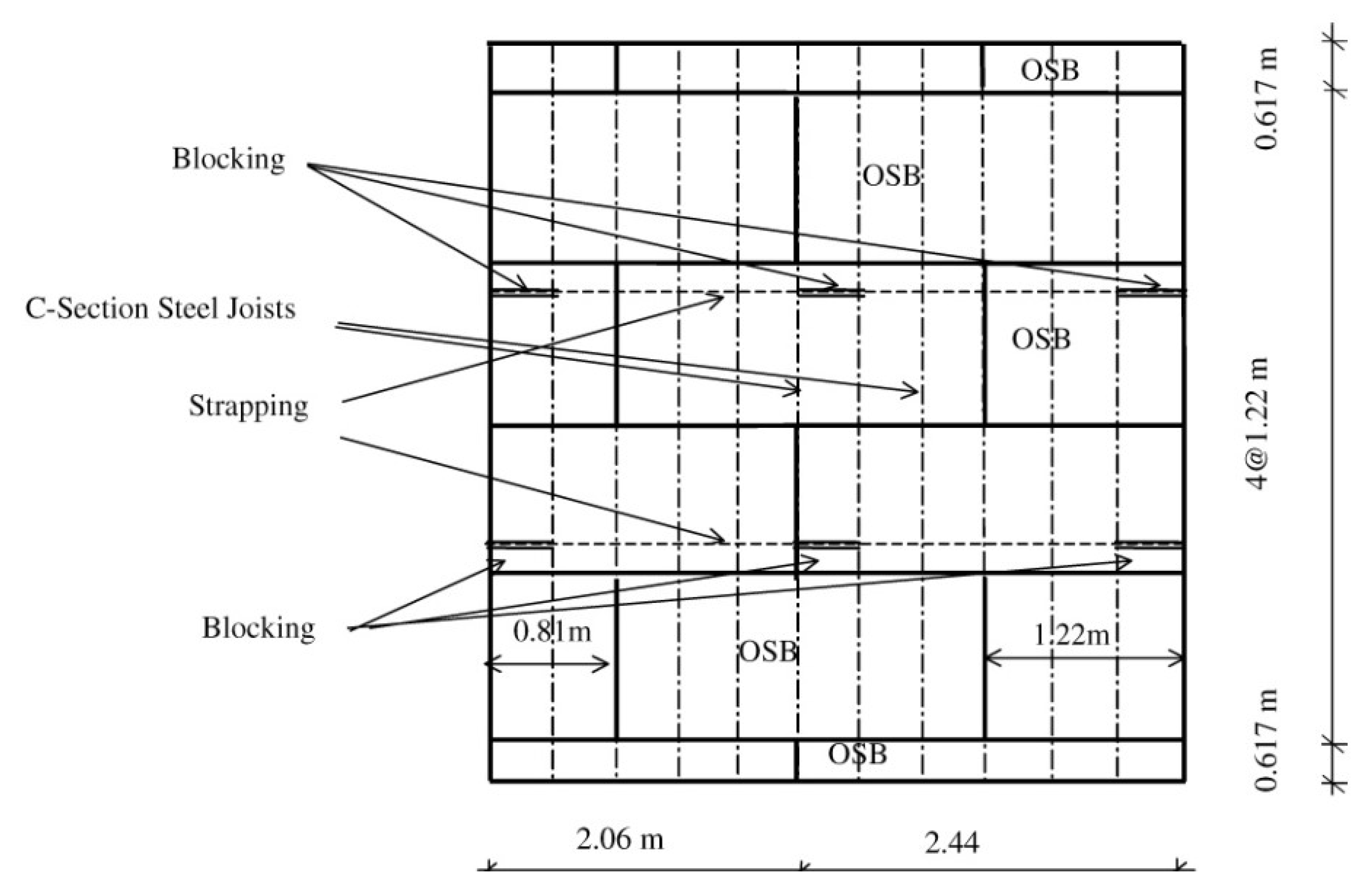
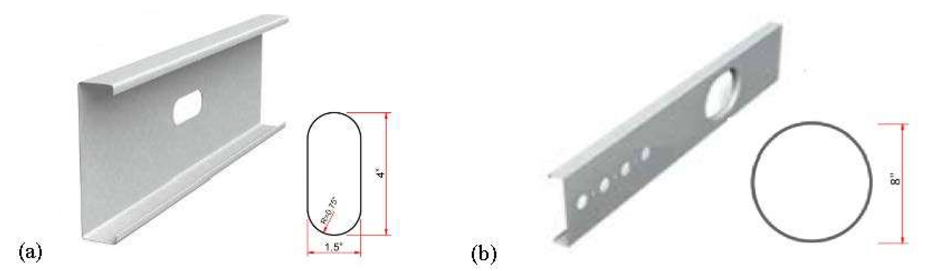
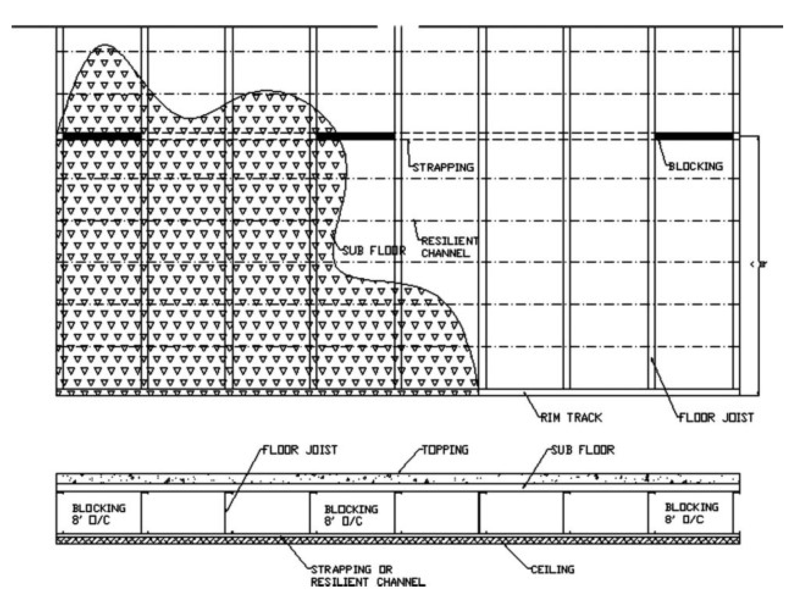
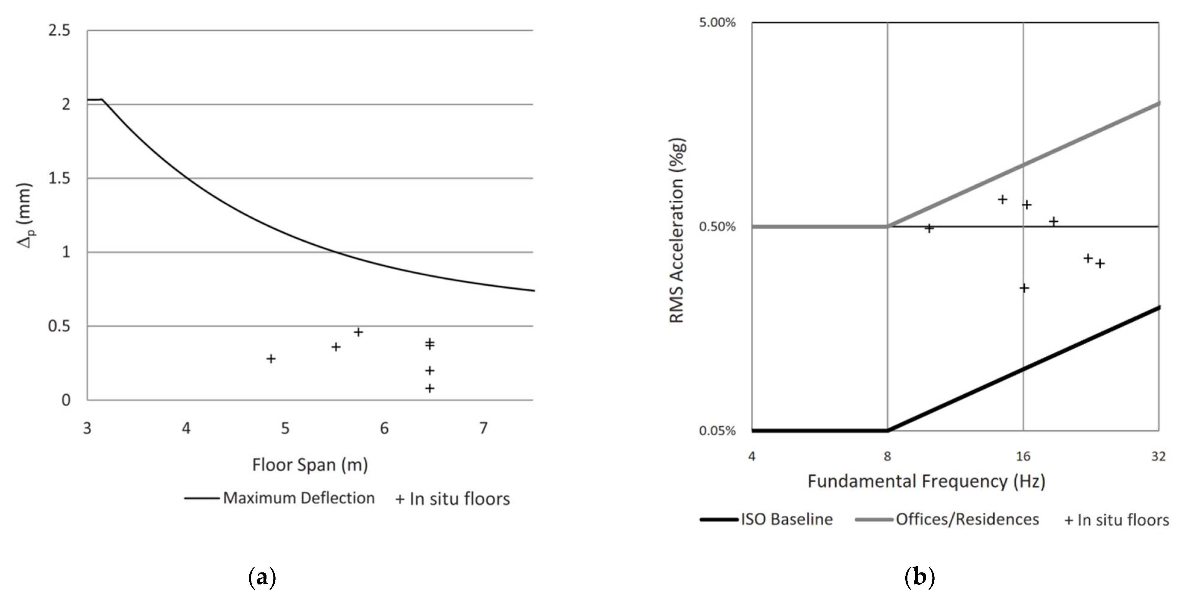
2. Experimental Studies on Vibration Performance of Lightweight Steel-Timber Floors
3. Experimental and Numerical Studies on Mass Timber Composite Floors Comprising Steel Beams and CLT Panels
4. Discussion
5. Conclusions
- ATC [19] and CWC [4] standard evaluate the vibration of lightweight timber floors due to walking based on very simple deflection limits. Although these limits can be employed in the design of conventional wood-frame floors with high frequencies (i.e., more than 8 Hz), they may be sufficient for STC floors with heavier subfloors such as CLT, NLT, or LVL.
- Very limited studies have examined the validity of Eurocode 5 equations in designing STC floors. According to Eurocode 5, floors with a frequency less than 8 Hz need a special investigation, while floors with a frequency of more than 8 Hz can be designed based on the vibration limit provided in this standard.
- CCIP-016 [1] was originally proposed for concrete structures and is currently being used in the vibration design of floors in mass timber buildings. Although using CCIP-016 [1] for the vibration assessment of timber floors is recommended by some experts in industry (e.g., see [31]), its accuracy for STC floors has not been clearly investigated within the research community.
- Both AISC design 11 [2] and CCIP-016 [1] provide two different approaches (simplified equations and FE analysis methods) to address floor vibration. To the authors’ knowledge, the simplified equations in these guides have been calibrated for concrete and steel floors and may not be applicable to all timber composite floors. Furthermore, such equations cannot be used for irregular floors with large openings or cantilevers. Thus, using such simplified equations for long-span timber floors is currently not recommended. As an alternative to general equations, FE analysis is suggested for such systems. FE models enable the structural analyst to consider more details in their vibration assessment of composite floors. For this purpose, it is vital to conduct a proper modal analysis and capture higher modes of vibration correctly to evaluate the behavior of such floors with confidence.
- SCI P354 [8] presented vibration criteria for cold-formed steel framing floors. Such criteria are based on frequency, 1 kN deflection, and response factor (or VDV). However, in the case of using hot-rolled steel joists or heavy subfloors such as CLT, LVL, or NLT, there is no recommendation or criterion in SCI P354 [8]. Hence, SCI P354 [8] may not be applicable to STC floors.
- Canadian CLT Handbook [6] and CSA O86-19 [5] use an analytical equation for the vibration-controlled span design of CLT floors. This simplified equation is intended for only a one-span simply supported floor. The applicability of this equation for STC has not been examined. It is believed that this equation is too conservative for STC floors with CLT subfloors.
Author Contributions
Funding
Institutional Review Board Statement
Informed Consent Statement
Data Availability Statement
Acknowledgments
Conflicts of Interest
Appendix A. Analytical Equations for the Floor Vibration according to SCI P354

| Span length (m) | 3.5 | 3.8 | 4.2 | 4.6 | 5.3 | 6.2 |
| Deflection (mm) | 1.7 | 1.6 | 1.5 | 1.4 | 1.3 | 1.2 |
| Place | VDV Value for Low Probability of Adverse Comment |
|---|---|
| Buildings: 16 h day | 1.6 |
| Buildings: 8 h night | 0.51 |
Appendix B. Analytical Equations for the Floor Vibration according to Eurocode 5

Appendix C. Analytical Equations for the Floor Vibration according to CCIP-016
| Environment | Response Factor |
|---|---|
| Critical working areas | 1 |
| Residence-day | 2–4 |
| Residence-night | 1.4 |
| Office | 4 |
| Workshop | 8 |
| Environment | Maximum Footfall Rates footfalls/s |
|---|---|
| Footbridges | 2.5 |
| Corridor and circulation zones in any building | 2.5 |
| Within office bays and residential rooms (i.e., not corridor zones) | 2.0 |
| Within laboratories, operating theatres, and the like | 1.8 |
Appendix D. Analytical Equations for the Floor Vibration according to AISC Design Guide 11

| fn (Hz) | h |
|---|---|
| 9–11 | 5 |
| 11–13.2 | 6 |
| 13.2–15.4 | 7 |
References
- Willford, M.R.; Young, P.; CEng, M. A Design Guide for Footfall Induced Vibration of Structures; Concrete Society for The Concrete Centre: London, UK, 2006. [Google Scholar]
- Murray, T.M.; Allen, D.E.; Ungar, E.E.; Davis, D.B. Vibrations of Steel-Framed Structural Systems Due to Human Activity: AISC Design Guide 11; American Institute of Steel Construction: Chicago, LI, USA, 2016. [Google Scholar]
- EN 1995-1-1; Eurocode 5: Design of Timber Structures-Part 1-1: General-Common Rules and Rules for Buildings. CEN: Brussels, Belgium, 2004.
- Canadian Wood Council. Development of Design Procedures for Vibration Controlled Spans Using Engineered Wood Members; Canadian Wood Council: Ottawa, ON, Canada, 1997. [Google Scholar]
- CSA O86-19; Engineering design in wood. Canadian Standards Association: Toronto, ON, Canada, 2019.
- Karacabeyli, E.; Gagnon, S. Canadian CLT Handbook; FPinnovation: Vancouver, BC, Canada, 2019. [Google Scholar]
- E710-Minimizing Floor Vibration by Design And Retrofit; APA—The Engineered Wood Association: Tacoma, DC, USA, 2004.
- Smith, A.L.; Hicks, S.J.; Devine, P.J. Design of Floors for Vibration: A New Approach; Steel Construction Institute Ascot: Berkshire, UK, 2007. [Google Scholar]
- Hu, L.J.; Chui, Y.H.; Onysko, D.M. Vibration serviceability of timber floors in residential construction. Prog. Struct. Eng. Mater. 2001, 3, 228–237. [Google Scholar] [CrossRef]
- Negreira, J.; Trollé, A.; Jarnerö, K.; Sjökvist, L.-G.; Bard, D. Psycho-vibratory evaluation of timber floors—Towards the determination of design indicators of vibration acceptability and vibration annoyance. J. Sound Vib. 2015, 340, 383–408. [Google Scholar] [CrossRef]
- Weckendorf, J.; Toratti, T.; Smith, I.; Tannert, T. Vibration serviceability performance of timber floors. Eur. J. Wood Prod. 2016, 74, 353–367. [Google Scholar] [CrossRef]
- Basaglia, B.M. Dynamic Behaviour of Long-Span Timber Ribbed-Deck Floors. Ph.D. Thesis, University of Technology Sydney, Sydney, Australia, 2019. [Google Scholar]
- Movaffaghi, H.; Pyykkö, J. Vibration performance of timber-concrete composite floor section—Verification and validation of analytical and numerical results based on experimental data. Civ. Eng. Environ. Syst. 2022, 39, 165–184. [Google Scholar] [CrossRef]
- Zhang, L.; Zhou, J.; Chui, Y.H.; Li, G. Vibration Performance and Stiffness Properties of Mass Timber Panel–Concrete Composite Floors with Notched Connections. J. Struct. Eng. 2022, 148, 04022136. [Google Scholar] [CrossRef]
- Ussher, E.; Arjomandi, K.; Smith, I. Status of vibration serviceability design methods for lightweight timber floors. J. Build. Eng. 2022, 50, 104111. [Google Scholar] [CrossRef]
- Thai, M.-V.; Elachachi, S.M.; Ménard, S.; Galimard, P. Vibrational behavior of cross-laminated timber-concrete composite beams using notched connectors. Eng. Struct. 2021, 249, 113309. [Google Scholar] [CrossRef]
- Zhao, X.; Huang, Y.; Fu, H.; Wang, Y.; Wang, Z.; Sayed, U. Deflection test and modal analysis of lightweight timber floors. J. Bioresour. Bioprod. 2021, 6, 266–278. [Google Scholar] [CrossRef]
- Onysko, D.M.; Hu, L.J.; Jones, E.D.; Di Lenardo, B. Serviceability design of residential wood framed floors in Canada. In Proceedings of the World Conference on Timber Engineering, Vancouver, BC, Canada, 31 July–3 August 2000. [Google Scholar]
- ATC. Design Guide 1: Minimizing Floor Vibration; Applied Technology Council: Redwood City, CA, USA, 1999. [Google Scholar]
- Ohlsson, S. Springiness and Human-Induced Floor Vibrations: A Design Guide; Swedish Council for Building Research: Stockholm, Sweden, 1988. [Google Scholar]
- AS 3623; Domestic Metal Framing. Standards Association of Australia: Sydney, Australia, 1993.
- Dolan, J.D.; Murray, T.M.; Johnson, J.R.; Runte, D.; Shue, B.C. Preventing annoying wood floor vibrations. J. Struct. Eng. 1999, 125, 19–24. [Google Scholar] [CrossRef]
- Hu, L.J.; Chui, Y.H. Development of a design method to control vibrations induced by normal walking action in wood-based floors. In Proceedings of the 8th World Conference on Timber Engineering, Lahti, Finland, 14–17 June 2004; Volume 2, pp. 217–222. [Google Scholar]
- BSI. NA to BS EN 1991-1-1:2002; NA: UK National Annex to Eurocode 1: Actions on Structures—Part 1-1: General Actions—Densities, Self-Weight, Imposed Loads for Buildings. British Standards Institution: London, UK, 2002.
- Porteous, J.; Kermani, A. Structural Timber Design to Eurocode 5; Wiley-Blackwell: Oxford, UK, 2007. [Google Scholar]
- Toratti, T.; Talja, A. Classification of Human Induced Floor Vibrations. Build. Acoust. 2006, 13, 211–221. [Google Scholar] [CrossRef]
- ISO 10137; Bases for design of structures Serviceability of buildings and walkways against vibrations. International Standards Organization: Geneva, Switzerland, 2007.
- ISO 2631-2; Evaluation of Human Exposure to Whole Body Vibration—Part 2: Human Exposure to Continuous Shock-Induced Vibrations in Builidngs (1 to 80 Hz). British Standards Institution: London, UK, 1989.
- BS 6472-1:2008; Guide to evaluation of human exposure to vibration in buildings–Part 1: Vibration sources other than blasting. British Standards Institution: London, UK, 2008.
- Barber, D.; Blount, D.; Hand, J.J.; Roelofs, M.; Wingo, L.; Woodson, J.; Yang, F. Design Guide 37: Hybrid Steel Frames with Wood Floors; American Institute of Steel Construction: Chicago, IL, USA, 2022. [Google Scholar]
- U.S. Mass Timber Floor Vibration Design Guide, 1st ed.; WoodWorks—Wood Products Council: Washington, DC, USA, 2021.
- Basaglia, B.M.; Li, J.; Shrestha, R.; Crews, K. Response Prediction to Walking-Induced Vibrations of a Long-Span Timber Floor. J. Struct. Eng. 2021, 147, 04020326. [Google Scholar] [CrossRef]
- Kraus, C.A. Floor Vibration Design Criterion for Cold-Formed C-Shaped Supported Residential Floor Systems. Ph.D. Thesis, Virginia Tech, Blacksburg, VA, USA, 1997. [Google Scholar]
- Xu, L.; Tangorra, F. Experimental investigation of lightweight residential floors supported by cold-formed steel C-shape joists. J. Constr. Steel Res. 2007, 63, 422–435. [Google Scholar] [CrossRef]
- Parnell, R.; Davis, B.W.; Xu, L. Vibration Performance of Lightweight Cold-Formed Steel Floors. J. Struct. Eng. 2010, 136, 645–653. [Google Scholar] [CrossRef]
- Xu, L. Floor Vibration in Lightweight Cold-Formed Steel Framing. Adv. Struct. Eng. 2011, 14, 659–672. [Google Scholar] [CrossRef]
- Liu, W. Vibration of Floors Supported by Cold-Formed Steel Joists; University of Waterloo: Waterloo, ON, Canada, 2001. [Google Scholar]
- Murray, T.M.; Allen, D.E.; Ungar, E.E. Floor Vibrations Due to Human Activity; American Institue of Steel Construction: Chicago, IL, USA, 1997. [Google Scholar]
- Smith, I.; Chui, Y.H. Design of lightweight wooden floors to avoid human discomfort. Can. J. Civ. Eng. 1988, 15, 254–262. [Google Scholar] [CrossRef]
- Zhang, S.; Xu, L. Vibration serviceability evaluation of lightweight cold-formed steel floor systems. Structures 2022, 38, 1368–1379. [Google Scholar] [CrossRef]
- Wiss, J.F.; Linehan, P.W.; Kudder, R.J. Report of Laboratory Tests and Analytical Sudies of Structural Characteristics of Cold-Formed Steel-Joist Floor Systems; Janney, Elstner & Associates, Inc.: Rolla, MO, USA, 1977. [Google Scholar]
- Kullaa, J.; Talja, A. Vibration tests for lightweight steel joist floors–subjective perceptions of vibrations and comparisons with design criteria. In Proceedings of the Finnish R&D Conference on Steel Structure (Teräsrakenteiden tutkimus-ja kehityspäivät), Lappeenranta, Finland, August 1998. [Google Scholar]
- Samuelsson, M.; Sandberg, J. Vibrations in Lightweight Steel Floors; Swedish Institute of Steel Construction: Stockholm, Sweden, 1998; p. 190. [Google Scholar]
- Huang, H.; Gao, Y.; Chang, W.-S. Human-induced vibration of cross-laminated timber (CLT) floor under different boundary conditions. Eng. Struct. 2019, 204, 110016. [Google Scholar] [CrossRef]
- Wang, C.; Chang, W.-S.; Yan, W.; Huang, H. Predicting the human-induced vibration of cross laminated timber floor under multi-person loadings. Structures 2020, 29, 65–78. [Google Scholar] [CrossRef]
- Cai, Y.; Gong, G.; Xia, J.; He, J.; Hao, J. Simulations of human-induced floor vibrations considering walking overlap. SN Appl. Sci. 2020, 2, 19. [Google Scholar] [CrossRef]
- Chiniforush, A.A.; Alamdari, M.M.; Dackermann, U.; Valipour, H.; Akbarnezhad, A. Vibration behaviour of steel-timber composite floors, part (1): Experimental & numerical investigation. J. Constr. Steel Res. 2019, 161, 244–257. [Google Scholar] [CrossRef]
- Khorsandnia, N.; Valipour, H.; Bradford, M. Deconstructable timber-concrete composite beams with panelised slabs: Finite element analysis. Constr. Build. Mater. 2018, 163, 798–811. [Google Scholar] [CrossRef]
- Bernard, E.S. Dynamic Serviceability in Lightweight Engineered Timber Floors. J. Struct. Eng. 2008, 134, 258–268. [Google Scholar] [CrossRef]
- Labonnote, N.; Rønnquist, A.; Malo, K.A. Prediction of material damping in timber floors, and subsequent evaluation of structural damping. Mater. Struct. 2014, 48, 1965–1975. [Google Scholar] [CrossRef]
- Wyatt, T.A. Design Guide on the Vibration of Floors; SCI Publication: London, UK, 1989. [Google Scholar]
- Allen, D.E. Building vibrations from human activities. Concr. Int. 1990, 12, 66–73. [Google Scholar]
- Hassanieh, A.; Chiniforush, A.; Valipour, H.; Bradford, M. Vibration behaviour of steel-timber composite floors, part (2): Evaluation of human-induced vibrations. J. Constr. Steel Res. 2019, 158, 156–170. [Google Scholar] [CrossRef]
- Feldmann, M.; Heinemeyer, C.; Butz, C.; Caetano, E.; Cunha, A.; Galanti, F.; Goldack, A.; Hechler, O.; Hicks, S.; Keil, A.; et al. Design of Floor Structures for Human Induced Vibrations; JRC–ECCS joint report; Publications Office of the European Union: Brussels, Belgium, 2009. [Google Scholar]
- Zhang, B.; Rasmussen, B.; Jorissen, A.; Harte, A. Comparison of vibrational comfort assessment criteria for design of timber floors among the European countries. Eng. Struct. 2013, 52, 592–607. [Google Scholar] [CrossRef]
- Hu, L.J. Serviceability Design Criteria for Commercial and Multi-Family Floors; Canadian Forestry Service: Canada; Australia, 2000. [Google Scholar]
- Ebadi, M.M. Vibration Behaviour of Glulam Beam-and-Deck Floors; Université d’Ottawa/University of Ottawa: Ottawa, ON, Canada, 2017. [Google Scholar]
- Ebadi, M.M.; Doudak, G.; Smith, I. Evaluation of floor vibration caused by human walking in a large glulam beam and deck floor. Eng. Struct. 2019, 196, 109349. [Google Scholar] [CrossRef]
- Shahnewaz, M.; Dickof, C.; Zhou, J.; Tannert, T. Vibration and flexural performance of cross-laminated timber—Glulam composite floors. Compos. Struct. 2022, 292, 115682. [Google Scholar] [CrossRef]
- Christian, S.; Carla, D.; Fast, T. Evaluation of a long span mass timber floor under footfall vibration loads. In Proceedings of the CSCE 2022—CSCE Annual Conference, Las Vegas, NV, USA, 25–28 July 2022. [Google Scholar]


| Floorboard Thickness and Type | Cold-Formed Steel Joist Type | Span (m) | Frequency (Hz) | Maximum Deflection (mm) | Damping Ratio (%) | |
|---|---|---|---|---|---|---|
| Laboratory floors * | 16 mm OSB | C-203 × 41 × 1.22 C-254 × 41 × 1.91 | 4.12–6.754 | 10.51–15.98 | 1.01–1.69 | 1.29–2.59 |
| On-site unfinished floors * | 16 mm plywood | C-254 × 41 × 1.91 C-254 × 41 × 1.52 | 5.089–5.912 | 14.9–18.0 | 0.91–1.20 | 5–6 |
| On-site fully finished floors | 16 mm plywood | C-254 × 41 × 1.52 | 5.302 | 12.3–13.6 | - | 6–6.5 |
| Span (m) | Joist Section | Subfloor | Floor Support System | Framing | |
|---|---|---|---|---|---|
| Laboratory floors | 4.42 | CSW&TDW | OSB, FC, FC with LR | free support | Balloon framing Platform framing |
| 5.18–5.94 | TDW | UFS with LR FC with LR | |||
| In situ floors | 4.51–6.46 | TDW | FC with LR UFS with LR | supported on all four sides | Balloon framing |
Notes:
| |||||
| Span (m) | Frequency, f1 (Hz) | Damping Ratio, β (%) | Maximum Deflection (mm) | |
|---|---|---|---|---|
| Laboratory floors (Balloon framing) | 4.42–5.94 | 11.4–26.3 | 2.1–4.7 | 0.25–0.59 |
| Laboratory floors (Platform framing) | 4.42–5.94 | 11.1–17.9 | 3.5–7 | 0.25–0.67 |
| Laboratory floors (Simple support) | 4.42–5.94 | 10.6–19.1 | 2.3–7.7 | 0.26–0.71 |
| In situ floors (Balloon framing) | 4.51–6.46 | 14.4–16.6 | 7.1–8.8 | 0.28–0.46 |
| Fundamental Frequency (Hz) | Maximum Deflection (mm) | |
|---|---|---|
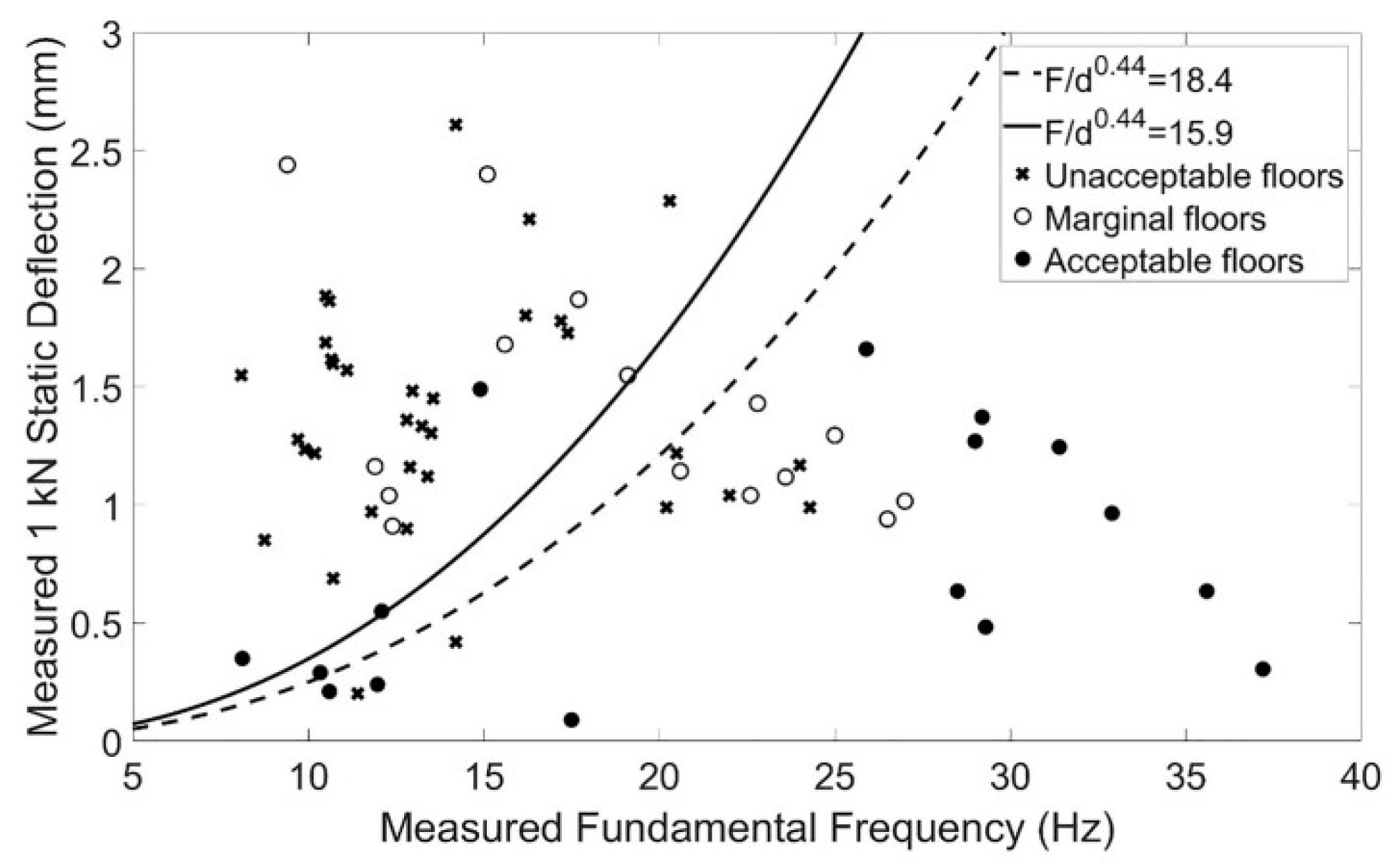
| Laboratory floors | 9.8–26.3 | 0.17–1.89 |
| In situ floors | 9.9–35.7 | 0.2–1.20 |
| Criteria Used for Span Design | |||
|---|---|---|---|
| ATC Deflection [19] | L/480 with Living Room | L/480 with Bedroom | |
| CWC method [4] | satisfactory | unsatisfactory | unsatisfactory |
| ATC method [19] | satisfactory | unsatisfactory | unsatisfactory |
| Swedish method [20] | satisfactory | satisfactory | unsatisfactory |
| Australian method [21] | satisfactory | satisfactory | satisfactory |
| Floorboard Type | Hot-Rolled Steel I-Beams | Floor Dimension | First Natural Frequency (Hz) | |
|---|---|---|---|---|
| Numerical | Experimental | |||
| 3-Ply CLT floor (t = 120 mm) | UB 406 × 140 × 46 UB 203 × 133 × 30 | 9.0 m × 6.6 m | 7.6 | 7.5 |
| Place and Time | Low Probability of Adverse Comment (m/s−1.75) | Adverse Comment Possible (m/s−1.75) | Adverse Comment Probable (m/s−1.75) |
|---|---|---|---|
| Residential buildings (16 h daytime) | 0.2 to 0.4 | 0.4 to 0.8 | 0.8 to 1.6 |
| Residential buildings (8 h nighttime) | 0.1 to 0.2 | 0.2 to 0.4 | 0.4 to 0.8 |
| Floor | Frequency (Hz) | aRMS (m/s2) | VDV (m/s−1.75) |
|---|---|---|---|
| No.1 | 7.6 | 0.321 | 0.613 |
| No.2 | 7.9 | 0.318 | 0.602 |
| No.3 | 2 | 0.615 | 1.9 |
| No.4 | 9.7 | 0.306 | 0.513 |
| No.5 | 9.8 | 0.321 | 0.528 |
| No.6 | 9.8 | 0.32 | 0.527 |
| No.7 | 9.7 | 0.309 | 0.514 |
| No.8 | 7.2 | 0.585 | 1.149 |
| No.9 | 7.7 | 0.339 | 0.667 |
| No.10 | 7.1 | 0.608 | 1.205 |
| No.11 | 7.2 | 0.614 | 1.212 |
| CLT Panels | Hot-Rolled Steel Beams | Span (m) | First Natural Frequency (Hz) | |
|---|---|---|---|---|
| FE Model | Experiments | |||
| 3-Ply CLT with the thickness of 105 mm | HN 450 200 mm | 6.0 | 5.16 | 5.21 |
| Floor Panel | Panel Dimension (m) | Shear Connector * | CLT-to-CLT Connection | ||
|---|---|---|---|---|---|
| Parallel Configuration | Perpendicular Configuration | Type | Spacing (mm) | ||
| CLT | 2 pcs 3.0 × 1.0 × 0.12 | 6 pcs 1.0 × 1.0 × 0.12 | bolt/screw | 250/300 | - |
| Floor Panel | Span (m) | Steel Joist | Parallel CLT Configuration | Perpendicular CLT Configuration | Damping Ratio |
|---|---|---|---|---|---|
| CLT | 5.8 | 310UB32 | 21.40–24.73 Hz | 17.19 Hz | less than 2% |
| Parameter | Support | Span (m) | Steel Joist | Aspect Ratio | CLT-to-CLT Connection | CLT Thickness (mm) | Slab Orientation | Connection Spacing (mm) * | Connection Type * |
|---|---|---|---|---|---|---|---|---|---|
| Type/ Value | Pined, Continuous, Discontinuous | 6, 8, 10 | 360UB44.7, 310UB32.0, 250UB25.7 | 1, 2, 3 | Continuous, Double screws, Without connection | 140, 160, 180 | Parallel, Perp. | 125, 250, 500 | Screw 16, Screw 12, BGP12 |
| Frequency (Hz) | 9.8–12.4 | 6.8–15.7 | 8.6–11.9 | 9.8 | 9.8 | 9.6–9.9 | 7.5–9.8 | 8.8–10.8 | 9.5–10.4 |
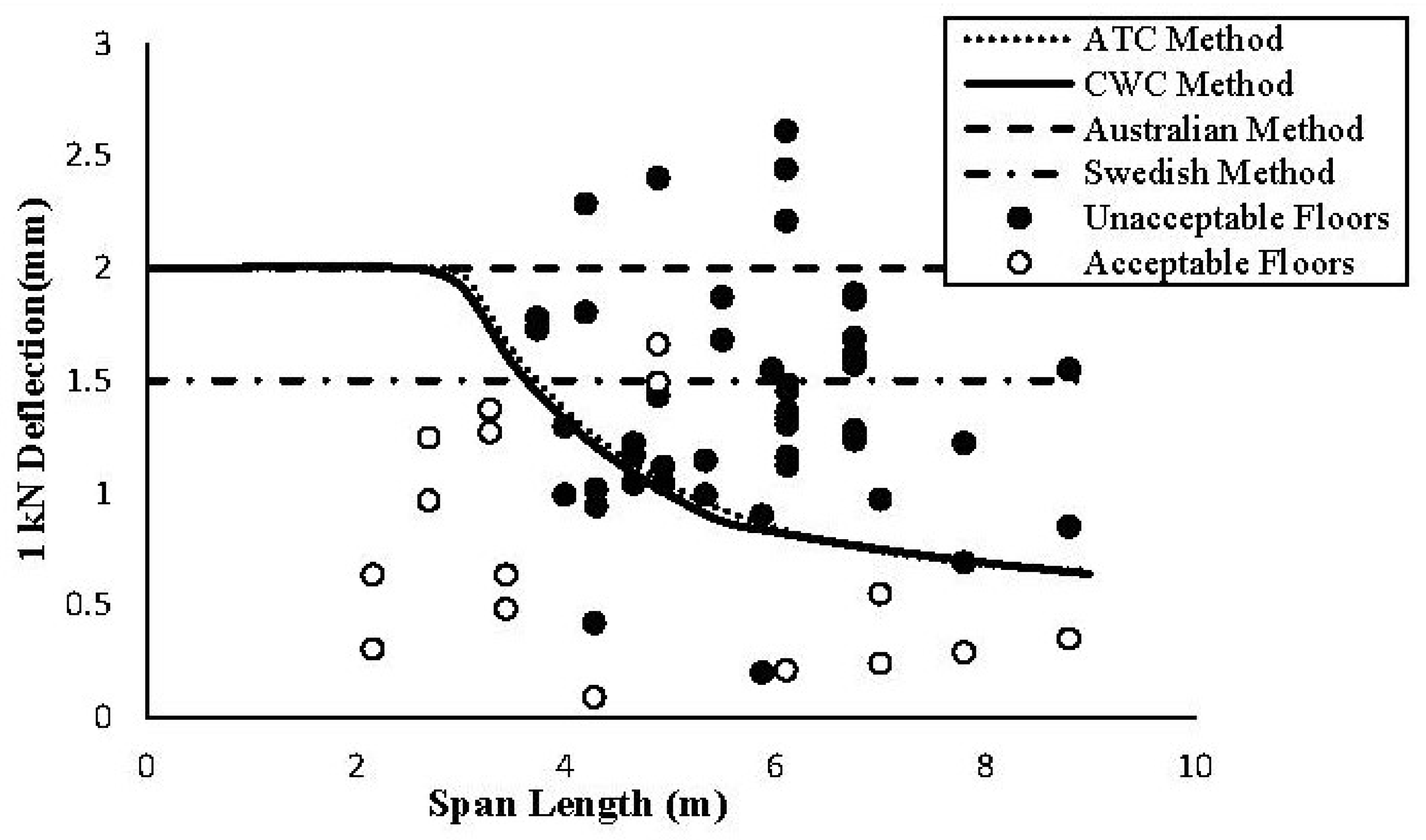
| Span Length | 2.16 < L < 8.8 m |
|---|---|
| Number of tested floors | 65 |
| Correctly predicted by CWC method * | 58 |
| Method’s accuracy | 89% |
| Work | CLT Panel Size (m) Length × Width × Thickness | Span (m) | Flexural Stiffness (N·m2) | Predicted Frequency * (Hz) | Measured Frequency ** (Hz) | Support |
|---|---|---|---|---|---|---|
| Chiniforush et al. [47] | 2 pcs 3.0 × 1.0 × 0.12 (S1CS∥), Figure 9 | 5.8 | 1.97 × 10⁷ | 21.7 | 24.16 | simply support |
| Wang et al. [45] | 6.6 × 5.6 × 0.105, Figure 6 | 6.0 | 6.02 × 10⁶ | 6.24 | 6.68 | partial simply support |
Publisher’s Note: MDPI stays neutral with regard to jurisdictional claims in published maps and institutional affiliations. |
© 2022 by the authors. Licensee MDPI, Basel, Switzerland. This article is an open access article distributed under the terms and conditions of the Creative Commons Attribution (CC BY) license (https://creativecommons.org/licenses/by/4.0/).
Share and Cite
Cheraghi-Shirazi, N.; Crews, K.; Malek, S. Review of Vibration Assessment Methods for Steel-Timber Composite Floors. Buildings 2022, 12, 2061. https://doi.org/10.3390/buildings12122061
Cheraghi-Shirazi N, Crews K, Malek S. Review of Vibration Assessment Methods for Steel-Timber Composite Floors. Buildings. 2022; 12(12):2061. https://doi.org/10.3390/buildings12122061
Chicago/Turabian StyleCheraghi-Shirazi, Najmeh, Keith Crews, and Sardar Malek. 2022. "Review of Vibration Assessment Methods for Steel-Timber Composite Floors" Buildings 12, no. 12: 2061. https://doi.org/10.3390/buildings12122061
APA StyleCheraghi-Shirazi, N., Crews, K., & Malek, S. (2022). Review of Vibration Assessment Methods for Steel-Timber Composite Floors. Buildings, 12(12), 2061. https://doi.org/10.3390/buildings12122061