Article

Investigation of the Deterioration of Medium-Rise-Wall Type Reinforced Concrete Buildings with External Insulation in Snowy Cold Districts

1
Faculty of Engineering, Hokkai-Gakuen University, Sapporo 064-0926, Japan
2
Faculty of Engineering, Hokkaido University of Science, Sapporo 006-8585, Japan
3
Faculty of Engineering, Hokkaido University, Sapporo 060-8628, Japan
4
Hokkaido Research Organization, Building Research Department, Asahikawa 078-8801, Japan
*
Author to whom correspondence should be addressed.
Buildings 2022, 12(12), 2048; https://doi.org/10.3390/buildings12122048
Submission received: 25 October 2022 / Revised: 17 November 2022 / Accepted: 21 November 2022 / Published: 22 November 2022
(This article belongs to the Special Issue The Impact of Building Materials on Construction Sustainability)

Abstract

:
We have clarified that external insulation reduces the probability of reinforcement corrosion in reinforced concrete buildings in cold snowy districts by 45–78%. Renovation of external insulation is one of the effective methods for improving the insulation performance and durability of reinforced concrete buildings, but there are almost no data that demonstrate durability. Therefore, the carbonation depth and the cover depth were investigated for six medium-rise-wall type reinforced concrete buildings in Hokkaido, Japan, which had been refurbished for external insulation. As a result, it was clarified that the external insulation suppressed the carbonation depth by 30% or more, even when the bonding method of the external insulation was different. In addition, it was clarified that the external insulation further suppressed carbonation in walls where the carbonation depth tended to increase in snowy cold districts. Specifically, external insulation reduced carbonation by up to 35% on surfaces that tend to dry out due to sunlight, and by 49% on surfaces that are affected by water that deteriorates the concrete surface layer.

1. Introduction

One of the fundamental goals in the world is sustainable development. Under such circumstances, materials covering buildings play an important role in the renovation of existing buildings from the viewpoint of energy conservation performance and durability of the materials. Mohamed, A. B. Omer et al. stated that the use of durable building materials is key to sustainable consumption, as it prioritizes minimizing the material resources used and the amount of waste produced [1].
On the other hand, the materials used to cover existing reinforced concrete buildings are required to not only have energy-saving performance and material durability, but also be able to protect the building frame. Cement used for reinforced concrete emits a large amount of CO2 during production, so it is important to increase the durability of reinforced concrete buildings as much as possible for long-term use. In Japan, the amount of CO2 generated during cement production is 24490kt per year, which accounts for 2.3% of total emissions [2]. One of the technologies that can contribute to this is external insulation renovation. The accumulation of data is necessary to verify the sustainability of these effects in a real environment.
In Hokkaido, Japan, external insulation renovation has been carried out since the 1980s. Hayama et al. revealed that energy consumption was reduced by 13 to 25% in housing complexes that had been renovated with external insulation [3].
In Europe, research is being conducted on improving thermal insulation performance through the following renovations: case studies of external insulation renovations aimed at improving energy efficiency under climatic conditions in various countries [4,5,6], and verification of the effect of the modification from the viewpoint of Life Cycle Assessment (LCA) [7]. Dora, S. et al. monitored and measured the temperature and humidity at the layer boundary when the flat roof of a building, located in Budapest, Hungary, was renovated into a glass, wool-filled, double-skin roof. [4]. Lucelia, R. et al. presented an external insulation system’s theoretical and experimental performance to improve the energy efficiency of old UK council housing [5]. Milorad, B. et al. evaluated the energy consumption of an uninsulated old house in Belgrade, Serbia by simulating the energy consumption of several renovation methods, including external insulation [6]. Beatriz Palacios-Munoz et al. calculated the environmental impact of refurbishing a residential area built in Zaragoza, Spain, and clarified the effect of refurbishment [7]. In this study, the lifespan of reinforced concrete buildings was also evaluated, but the improvement of structural performance due to external insulation renovation was not considered. Sheila Varela Luján and colleagues monitored the surface temperature of the façade of a building in Madrid, before and after renovation. As a result, it was revealed that the energy loss was reduced by 57% and the energy gain was reduced by 39% after implementing the ETICS façade renovation, as compared to before the renovation [8].
Research is also progressing on the durability of the external insulation itself.
In Hokkaido, Japan, external insulation using composite panels was often used in the 1980s. This consists of a certain size of insulation material with a fiber-reinforced cement board attached to the surface, and a waterproof seal between the panels. Here, problems, such as cracking and peeling due to repeated freezing and thawing of the water contained in the cement board, as well as water infiltration into the material due to aging deterioration of the waterproof sealing, were assessed [9]. Therefore, countermeasures, such as (1) using a material with a low water absorption rate for the surface layer, (2) using a coating material with high moisture permeability, and (3) ensuring the waterproofness of the sealing, have been proposed [9]. In response to this problem, Mori et al. developed an external thermal insulation composite board with a ventilation layer, which contributed to keeping the composite board dry [10].
In addition, F. Stazi et al. conducted research on the sustainability of the performance of external insulation materials. Twenty years later, they investigated an external insulation material introduced in the 1980s, and demonstrated its effectiveness and durability from a temperature/humidity measurement and mechanical point of view [11].
The external thermal insulation composite system (ETICS), which is widely used in Europe, is attracting attention from the viewpoint of improving energy efficiency through retrofitting, and research on its sustainability has been started. Márcio, G. et al. carried out temperature monitoring of an ETICS wall located in a Mediterranean climate, and clarified that the thermal conductivity of the insulation, as well as the optical properties of the finish paint color, were determinants of the thermal behavior of the ETICS wall. They also used infrared thermography inspection techniques to detect early signs of potential anomalies, such as cracks, blisters, and water intrusion [12]. João Tavares et al. developed a methodology for the service life prediction of ETICS systems based on the application of artificial neural networks and fuzzy logic system computation methods [13]. Eneli, L. et al. carried out laboratory tests on several combinations of reinforced mesh and finish coating for the ETICS surface layer, and demonstrated that the reinforcing the net reduced the dimensional change of the thin layer under the influence of climate. [14]. Clara, P. et al. investigated the deterioration of facade coverings, and suggested that ETICS had the highest incidence of humidity defects [15]. J.L. Parracha et al. exposed ETICS to marine and urban environments, and found that fungal growth was facilitated when the surface layer was lime-based [16].
On the other hand, the protection of the frame is a secondary effect of the external insulation renovation. In reinforced concrete buildings, the protection of the building frame by external insulation may greatly contribute to durability improvement, but there are few examples of actual measurements in actual buildings.
Xuehan et al. investigated the air permeability of external insulation and the carbonation of concrete by using accelerated carbonation tests. As a result, it has been clarified that there is a relationship between the air permeability coefficient of the external insulation material and the carbonation depth, and that the carbonation suppression effect of the external insulation method can be evaluated to some extent by the air permeability coefficient [17]. In this research, when dolomite-mixed mortar was used as the exterior material of rock wool insulation, it was confirmed that the air permeability coefficient was greatly reduced from 27 to 0.19 (cm4/N s).
The carbonation depth of concrete can be reduced by covering the concrete surface with a cladding [18,19]. Hasegawa et al. studied the progress of carbonation in concrete coated with a finishing coating material, and found that the moisture permeability of the coating material affected the progress of carbonation of concrete; as well, the color difference of the coating material changed over time. We have experimentally shown that the carbonation suppression effect does not change at time points [19].
In this way, the carbonation-suppressing effect of the materials themselves has been clarified, but when covering buildings with them, if they have seamless external insulation, expansion and contraction due to solar radiation and temperature will become a problem. In the case of external insulation with seams, aging deterioration of the filler material at the seams becomes a problem. When it is used in buildings, the question is whether it will exhibit the effect of suppressing carbonation, which includes long-term changes in the material.
Most of Japan belongs to the temperate zone, but Hokkaido is the only region in Japan that belongs to the Dfb (subarctic) climate classification of Köppen. Therefore, external insulation has been used since the 1970s. We surveyed six reinforced concrete buildings that had been renovated for external insulation. Renovation methods include “ETICS” and a unique Japanese construction method called “the composite panel construction method”. More than 30 years have passed since each of the six buildings was renovated. We were able to conduct a visual inspection and a sampling survey to confirm the degree of deterioration of the external materials, external insulation members, and the building frame.
In this paper, we report the results of research and analysis on the durability of concrete frames covered with external insulation. The purpose is to confirm that the presence or absence of external insulation affects the durability of reinforced concrete exterior walls.

2. Materials and Methods

2.1. Survey Target Building

Table 1 shows the information on the surveyed buildings. The surveyed buildings are apartments built in three areas. Building (Bldg.) A and B, C and D, and E and F were each constructed in the same area. Each region belongs to the Köppen climate classification Dfb, with an annual average total snow depth of more than 4m. All buildings were renovated with external insulation in the 1980s, primarily to prevent condensation. The scope of renovations varied from building to building.
Figure 1 shows the relationship between the layout of each building and the position of external insulation renovation. External insulation renovations were carried out on both the gable sides and the non-balcony side. There was a staircase on the non-balcony side, but in some cases, the outer wall of the staircase was not renovated (Bldg. A, Bldg. E, Bldg. F).
Figure 2 shows a cross-sectional view of the external insulation of each building. External insulation materials include expanded calcium carbonate (ECC), extruded poly-styrene (XPS), expanded poly-styrene (EPS), and polyurethane foam (PF). Fiber-reinforced cement boards (FRC), mortar with mesh sheets, and calcium silicate boards were used to protect them.
Both adhesives and fasteners were used to fasten the external insulation, except for Bldg. F. In Bldg. A to D, the external insulation panels were fixed to the reinforced concrete outer wall with adhesives and fasteners, and the gap between the panels was waterproofed with a sealing material. In addition, the method of applying the adhesive differed from building to building. Bldg. A and B were attached by applying combing adhesive to the entire back surface of the panel, and Bldg. C to E were attached with ball-shaped adhesives with diameters of about 100 mm at regular intervals. In Bldg. F, urethane foam was sprayed on as an external insulation material, so it stuck with its adhesive strength. The external insulation of Bldg. E was the so-called “ETICS”, in which external insulation was attached to the outer wall and the surface was seamlessly finished with mesh sheets and mortar. The external insulation of Bldg. F consisted of spraying urethane foam on the outer wall and then pasting a calcium silicate board on the wooden base as an external material.

2.2. Survey Items and Methods

Table 2 shows survey items, sampling locations, and the number of each measurement. In this study, to clarify the effects of the presence or absence of external insulation on the carbonation depth of concrete and the corrosion of rebars, concrete core sampling that included rebars was carried out at the same time that the building was dismantled. After that, the carbonation depth of the concrete cores and the cover thickness of the rebars were measured.

2.2.1. Concrete Sampling

Concrete core sampling positions were determined so that the difference in carbonation depth with and without external insulation on the same surface of each building would become clear. In addition, in Bldg. A, the sampling position was changed to understand the difference in the carbonation depth of the concrete due to the deterioration of the concrete surface layer. In Bldg. A, concrete flakes occurred under the window without external insulation due to the corrosion of rebars, so the comparison was made with the side of the window where such cracks did not occur. Furthermore, in Bldg. B, to understand the difference in carbonation depth of the concrete depending on the direction, the sampling position was set to each direction on the side of the foundation. Two or more samples were taken under the same conditions. Concrete cores were also taken at several other locations for cover thickness measurements.
In both cases, the concrete surface was searched in advance with an electromagnetic wave radar-type rebar detector to include vertical and horizontal rebars, and the sampling positions were determined. Concrete cores were sampled according to the Japanese standard JIS A 1107:2012 “Method of sampling and testing for compressive strength of drilled cores of concrete” based on ISO 1920-6. Concrete cores were taken with running water using a cylindrical rotary boring machine with a diamond cutter. Concrete cores were collected from the inside of the building for the walls and the outside of the building for the sides of the foundation. Figure 3. shows a detail of the concrete core. The shape of the concrete core is a cylinder with a diameter of about 83 mm and a height equal to the thickness of the wall.

2.2.2. Measuring Carbonation Depth of Concrete

The carbonation depth of the sampled concrete core was measured according to the Japanese standard JIS A 1152 “Method for measuring the carbonation depth of concrete”. Specifically, after washing the concrete core with fresh water, a 1% solution of phenolphthalein was sprayed on its side surface, and the distance from the concrete surface to the red-colored portion was measured using a scale. The number of measurement points was 6 or 5 (for Bldg. C) for the circumference of one cylindrical core.

2.2.3. Measure the Cover Thickness of the Rebar

The distance from the outer wall surface to the rebars was measured using a scale, and the minimum value was taken as the cover thickness.

3. Results and Discussion

3.1. Distribution of Rebar Cover Thickness

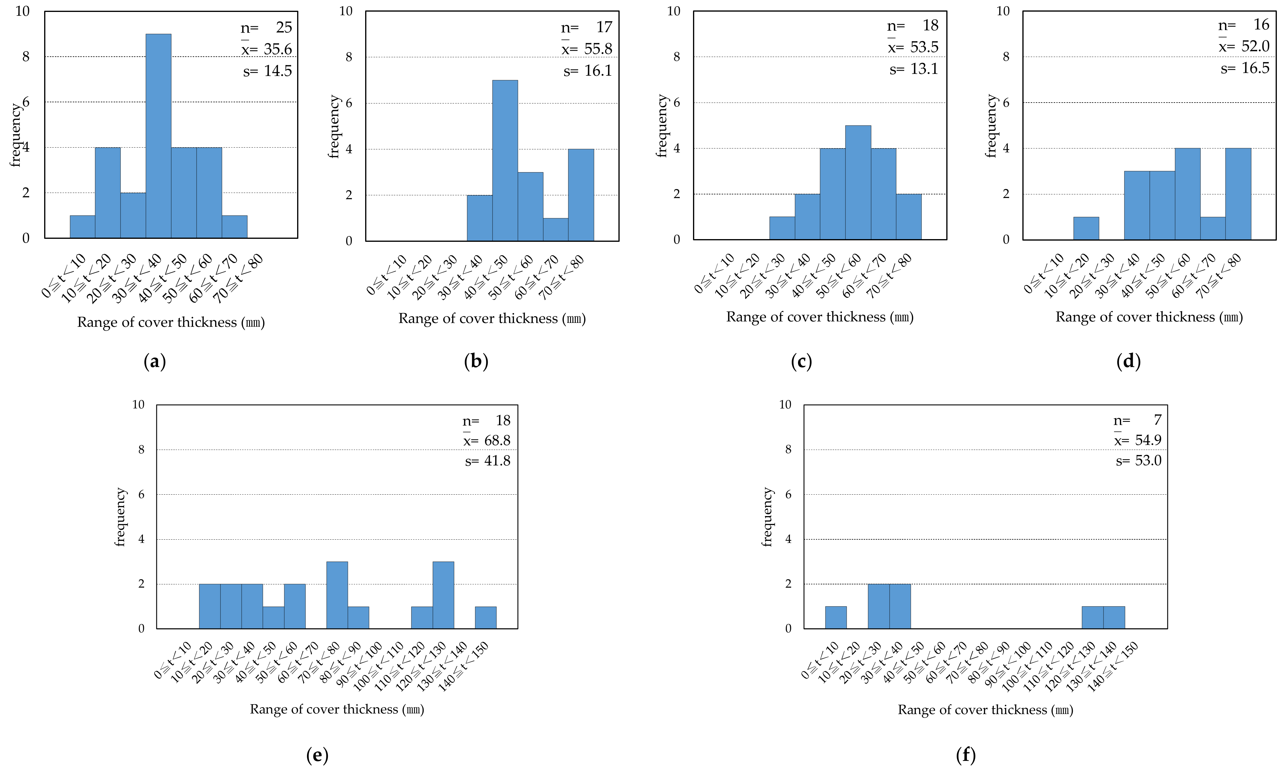
Figure 4 shows the distribution of cover thickness for each building. According to Article 79 of Japan’s Enforcement Ordinance of Construction Standard Law, the minimum cover thickness is 30 mm for load-bearing walls and 40 mm for the sides of continuous foundations.
In all buildings, the sample average exceeded the minimum value of each part, but not all rebars secured the minimum cover thickness. The reason for this is considered to be the low accuracy of the construction technology at the time of completion and the lack of attention to the durability of reinforced concrete. This indicated that the rebar cover thickness was small at some points in any building, and rebar corrosion due to carbonation would be likely to progress. Therefore, to accurately estimate the probability of reinforcement corrosion in buildings, it was necessary to use the survey results of concrete cover thickness and carbonation depth. The estimation of rebar corrosion probability considering the cover thickness and carbonation depth is performed in Section 3.3.
Izumi et al. investigated the cover thickness of reinforced concrete structures in Japan and clarified that the distribution of the cover thickness of rebars was close to the normal distribution [20]. In this survey as well, a similar tendency was confirmed as the number of samples increased. In addition, in a survey of several buildings by Izumi et al., the range of the standard deviation of the rebar cover thickness for each building was 11.2 to 19.1 mm, with an average value of 15.5 mm [20]. The standard deviations of Bldg. A to D showed similar trends, but buildings (Bldg.) E and F showed different trends. It is speculated that this is because Bldg. E and F were built in the 1960s and had a single layer of rebars in the walls.

3.2. Distribution of Carbonation Depth in Concrete

3.2.1. Effects of Concrete Deterioration

Figure 5 shows an example of the situation around the windows that we investigated. From the photograph, it can be seen that rebar corrosion and concrete spalling occurred on the wall under the window. The wall under the window was a part that was greatly affected by the water flowing down from the window, and rebar corrosion and frost damage caused by water occurs in cold regions. It is thought that carbonation progressed easily because the structure of the concrete became fragile due to these factors.
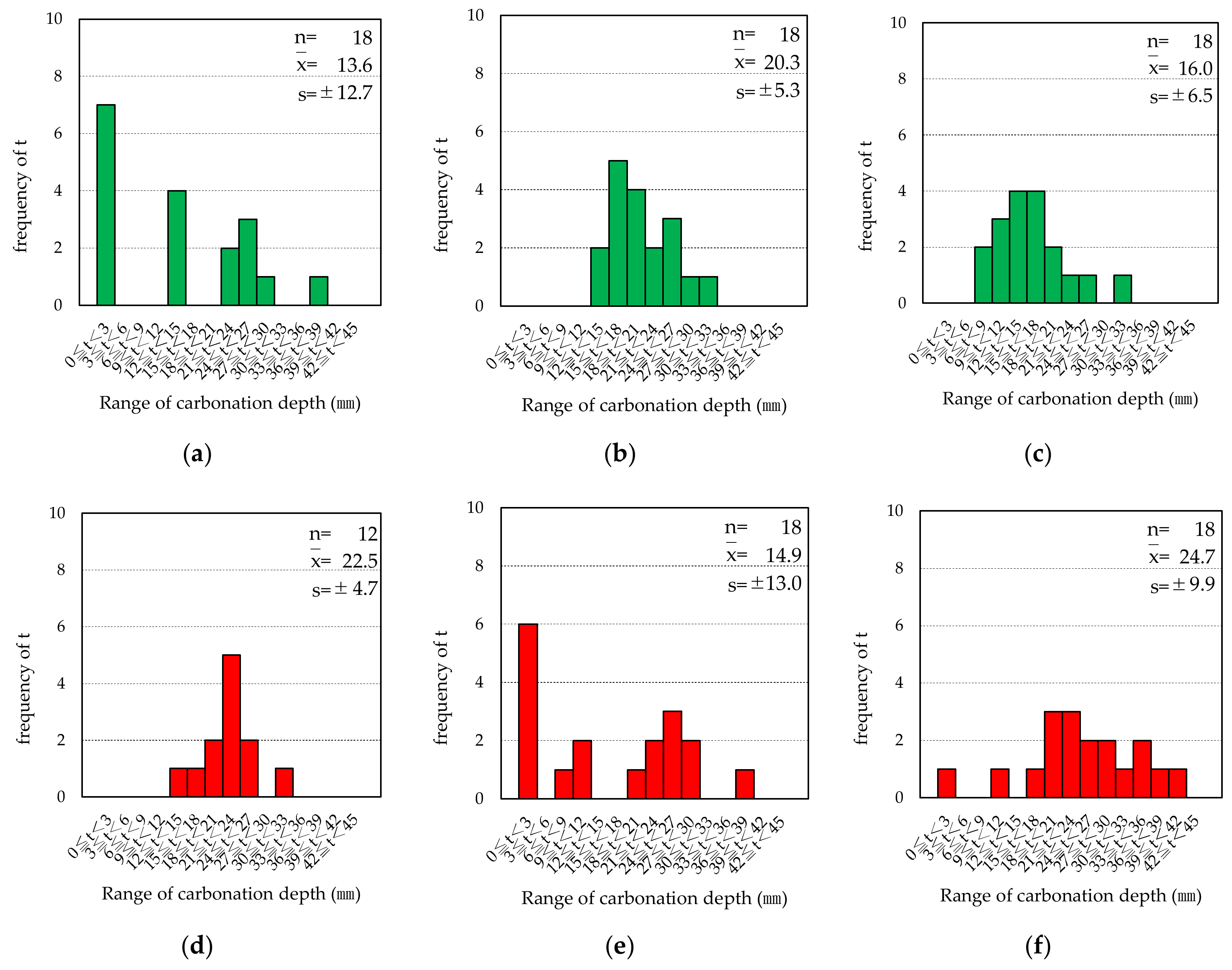
Figure 6 shows the distribution of carbonation depth below and beside the window on the outer wall of Bldg. A.
Below, the case with external insulation (EI) is indicated by a green graph, and the case without external insulation (NEI) is indicated by a red graph.
Izumi et al. investigated the distribution of carbonation depth in reinforced concrete structures in Japan and showed that the distribution was close to the normal distribution [20]. They were intended for fully carbonated cases. Since this survey includes data in which carbonation has not progressed sufficiently, the shape of the distribution may not be close to the normal distribution, but the mean and standard deviation were used as representative values of the distribution.
Table 3 shows representative values and analysis and test results for each condition. By looking at the mean of the carbonation depth in the case of NEI, we can see that carbonation was 54% less advanced on the wall beside the window than on the wall under the window. From this, it was clarified that carbonation progresses easily in sites exposed to water in cold districts.
Also, when comparing the carbonation depth of EI and NEI under the window, EI was lower (51%) against NEI (100%). Welch’s two-tailed t-test with a significance level of p < 0.01 was performed under the null hypothesis that the presence or absence of external insulation had no effect on the population, resulting in p = 0.000203.
From this, it can be said that external insulation suppressed the progress of carbonation in sites that were exposed to water in cold districts.
However, if water enters the rear surface due to deterioration of the external insulation or inter-panel sealing, the weakening of the concrete surface may progress further. Therefore, it can be said that it is important to periodically check the status of water protection measures for the external insulation surface at the lower part of the window.

3.2.2. Effects of Sunshine Hours

Figure 7 shows the distribution of the carbonation depth on the side of the foundation of Bldg. B.
There are two peaks northwest of the EI and northeast of the NEI. This was due to the presence of a concrete core in which carbonation had not progressed at all. The purpose of this investigation was to understand the difference in the progress of carbonation depending on the presence or absence of external insulation. Therefore, we decided to proceed with the study targeting concrete cores in which carbonation was progressing.
Table 4 shows various statistical values for concrete cores in which carbonation was progressing. Looking at the NEI data, it can be seen that the longer the daylight hour, the greater the carbonation depth that occurred. Izumi et al. also obtained similar results and explained that the longer the sunshine hours, the more the concrete dries and progresses carbonation [20].
On the other hand, looking at the carbonation depth ratio to the NEI wall, it can be seen that the longer the sunshine hours, the greater the decrease that occurred. Welch’s two-tailed t-test with a significance level of p < 0.01, performed under the null hypothesis that the presence or absence of external insulation had no effect on the population, resulted in p = 0.00448 < 0.01 in SE.
From the above, it was clarified that in walls with long hours of sunshine, the external insulation suppressed the drying of concrete due to solar radiation and the progress of carbonation.

3.2.3. Effects of Mortar Layer

Figure 8 shows the effect of external insulation on the carbonation depth of the outer wall concrete with a mortar layer at Bldg. E and F. In all cases, a rate of carbonation depth of less than 3 mm accounted for 88% or more, which indicated that carbonation hardly progressed.
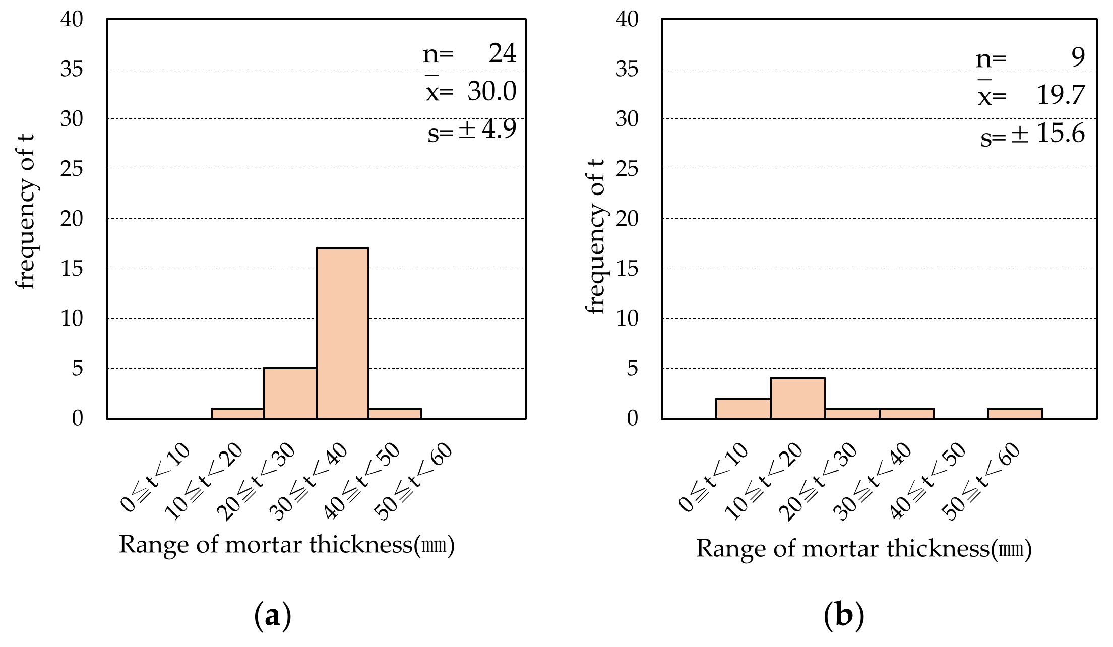
Figure 9 shows the distribution of mortar thickness for Bldg. E and F. The average mortar thickness was about 30 mm for Bldg. E and about 20 mm for Bldg. F. For comparison, Figure 10 shows the progress of carbonation in Bldg. A in the same direction.
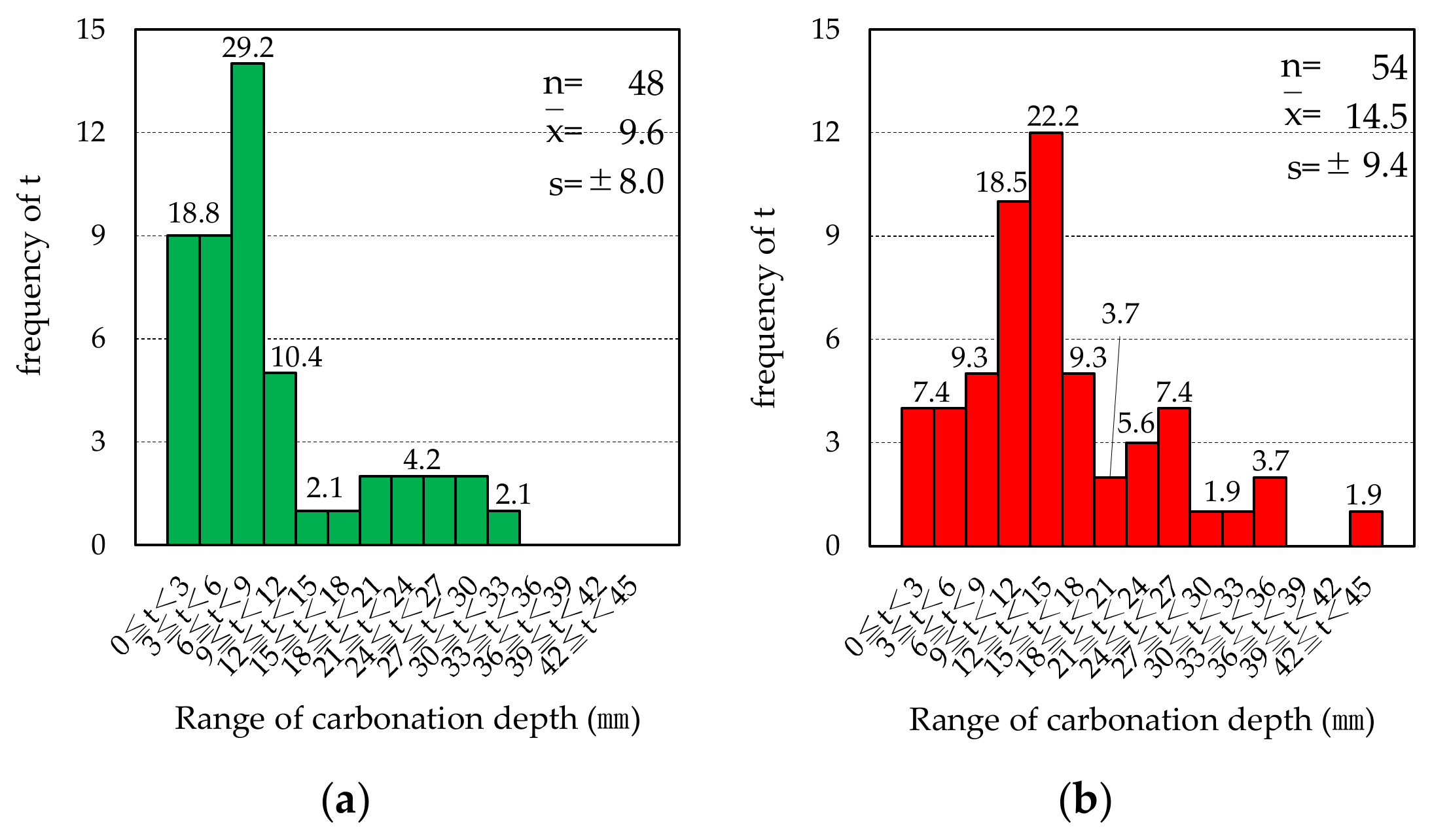
Since there was no mortar layer in Bldg. A, carbonation was progressing with NEI. On the other hand, when the mortar layer was present, carbonation hardly progressed even without external insulation.
In addition, when there was no mortar layer, such as in Bldg. A, the distribution approached that of the case with a mortar layer by providing external insulation. From this, it was clarified that the suppression of carbonation by external insulation worked effectively when the progress of carbonation was high.

3.2.4. Effect of Adhesive Application Method

The adhesives of the buildings whose walls were investigated at this time were ball-shaped in Bldg. C and D, and combing adhesives in Bldg. A.
Table 5 shows representative values and analysis and test results for each condition. Welch’s two-tailed t-test with a significance level of p < 0.01 was performed under the null hypothesis that the presence or absence of external insulation had no effect on the population. As a result, p < 0.01 was obtained for Bldg. D and Bldg. A. In Bldg. D., carbonation was reduced by 36% due to external insulation, and in Bldg. A, carbonation was reduced by 34% due to external insulation. A carbonation depth suppression effect of 30% or more was observed regardless of the adhesion method.
Next, in Bldg. A. and Bldg. D., where a clear effect of suppressing external insulation was confirmed, the difference in the suppressing effect due to the method of applying the adhesive was investigated. From the data obtained in this investigation, the progress of carbonation was predicted by the following formula.
The progress of carbonation was assumed to follow Equation (1). Equation (1) is the so-called “ t rule”, and its validity has been confirmed by Abe et al. [21] from the results of accelerated carbonation tests. The carbonation rate coefficient Anei without external insulation, the carbonation rate coefficient Aei after renovation of external insulation, and the intercept bei in that case are expressed by Equation (2), Equation (4), and Equation (3), respectively. Here, the following conditions are set.
  • The progress of carbonation follows Equation (1).
  • When the age of the building is 0 years, the carbonation depth is set to 0.
  • If there is no external insulation, Anei is obtained from Equation (2).
  • If there is external insulation, the progress of the carbonation of concrete will change before and after renovation. It is assumed that carbonation progresses in the same way as when there is no external insulation before repairing the external insulation. After refurbishment, the intercept bei is obtained by Equation (3) from the number of years elapsed until the refurbishment, the carbonation depth until the refurbishment, the number of years elapsed until the survey, and the carbonation depth at the time of the survey. In addition, the carbonation rate coefficient Aei is obtained from Equation (4):
    C t = A t + b ,
    A n e i = C n e i t s ,
    b e i = C e i t r A n e i t s t r t r t s ,
    A e i = A n e i t r b e i t r ,
    where Ct is the concrete carbonation depth at age t (mm), A is the carbonation rate coefficient (mm/ years ), t is the building age (years), b is the intercept, Anei is the carbonation rate coefficient without external insulation (mm/ years ), Cnei is the mean value of carbonation depth of investigated concrete without external insulation (mm), ts is the time of investigation elapsed age of the building (years), bei is the intercept of carbonation prediction formula after external insulation repair, Cei is the average value of carbonation depth of investigated concrete with external insulation (mm), tr is the repair elapsed age of the building (years), and Aei is the carbonation rate coefficient (mm/ years ) when there is external insulation.
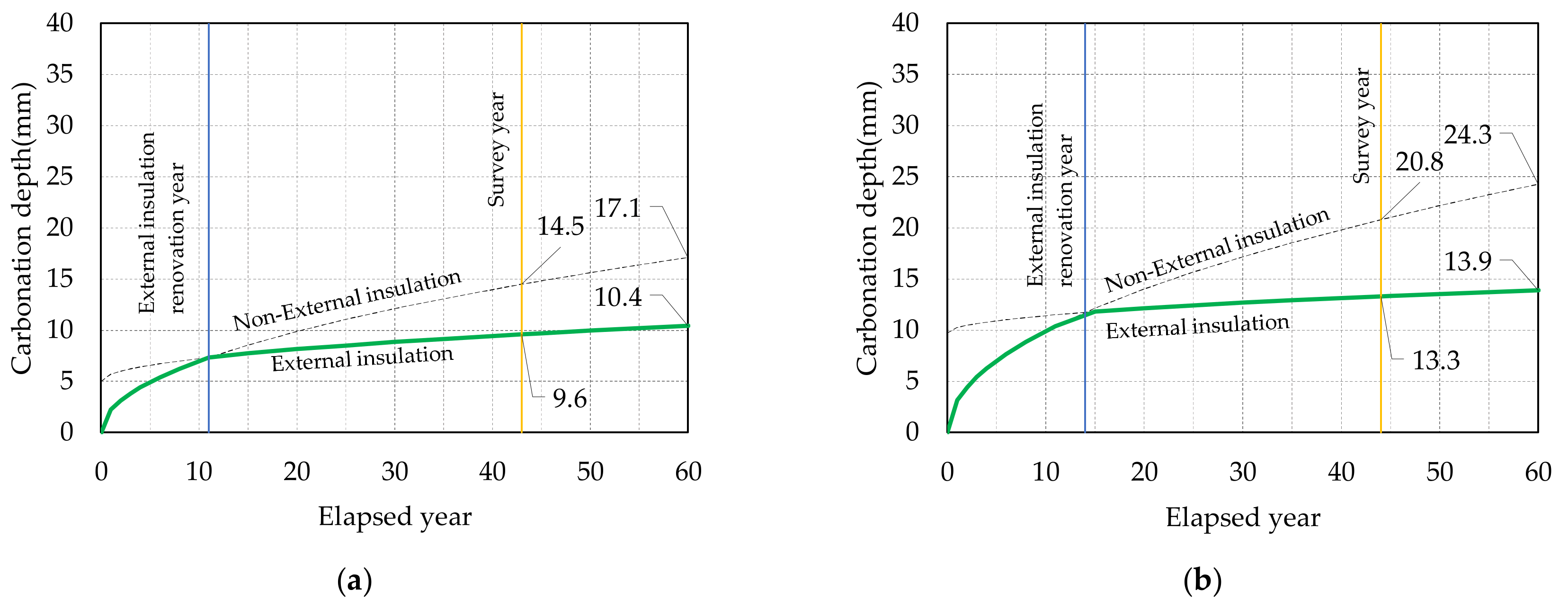
The results are shown in Figure 11.
From this, the carbonation suppression effect of the method of applying the adhesive was not clear. However, in all cases, carbonation only progressed by a few millimeters after external insulation was applied, which demonstrated a high carbonation suppression effect. When comparing 60-year-old buildings, it was expected that external insulation would reduce carbonation by 39.1% for Bldg. A. and 42.8% for Bldg. D.

3.3. Consideration of the Effect of External Insulation on the Probability of Rebar Corrosion Using a Probability Density Function

From the above survey results, it was found that the distribution of cover thickness and carbonation depth followed a normal distribution. Here, the difference in rebar corrosion probability with or without external insulation is clarified using the reliability design method of rebar cover thickness proposed by Izumi et al. [22].
The probability density function N (μCt, σCt2) of normal distribution with average value μCt and variance σCt2 for the carbonation depth x of concrete at a certain age t is expressed by the following equation:
f ( x ) = 1 2 π σ C t e ( x μ C t ) 2 2 σ C t 2 ,
Similarly, the probability density function N (μR, σR2) of the normal distribution with mean μR and variance σR2 for the rebar cover thickness y is expressed by the following equation:
g ( y ) = 1 2 π σ R e ( y μ R ) 2 2 σ R 2 ,
In addition, the difference z between the cover thickness y of the rebar and the carbonation depth x of the concrete at a certain age t has a normal distribution with mean value μRμCt and variance σR2 + σCt2. Its probability density function N (μRμCt, σR2 + σCt2) is expressed by the following equation:
h ( z ) = 1 2 π ( σ R 2 + σ C t 2 ) e ( z μ R + μ C t ) 2 2 ( σ R 2 + σ C t 2 ) ,
Based on the research results of Izumi et al. [22], it was assumed that the reinforcement starts to corrode when it reaches the cover thickness. In that case, the probability of z ≤ 0 is the corrosion probability P of the reinforcement:
P ( z 0 ) = 1 2 π ( σ R 2 + σ C t 2 ) 0 e ( z μ R + μ C t ) 2 2 ( σ R 2 + σ C t 2 ) ,
Table 6 shows the average μR and variance σR2 of the rebar cover thickness, the average μCt and variance σCt2 of the concrete carbonation depth, the reinforcing bar corrosion probability P(z = 0), and the test and analysis results for each building. The cumulative density at z = 0 is the rebar corrosion probability. In Bldg. C, carbonation did not progress so much, so there was no significant difference in the corrosion rate of rebars between the presence and absence of external insulation. On the other hand, in Bldg. A, about 11% of rebars were corroded in areas without external insulation and about 6% in areas with external insulation. These are considered to be the effects of external insulation, and the number of corroded rebars was reduced by approximately 48%. Similarly, in Bldg. D, it decreased by about 45%.
Since the cover thickness was large at the foundation, the corrosion probability of the rebars was not as high as at the outer wall. In the southeast, where carbonation was relatively advanced, external insulation reduced the number of corroded rebars by about 78%.
For both external walls and foundations, when a statistically significant difference was confirmed, it was found that external insulation greatly reduced the corrosion probability of the rebars.

4. Conclusions

In this study, it was clarified that the external insulation material attached with adhesive contributed to effectively lowering the probability of reinforcement corrosion in reinforced concrete. It worked particularly well in water-sensitive and dry areas where the carbonation depth tends to be large.
Specifically, the conclusions areas follows.
(1) In cold regions, external insulation suppressed the carbonation depth by 49% under the window, which was prone to surface deterioration due to the influence of water. It is thought that this is mainly because the external insulation blocks water, so it is important to regularly check the water protection status of the external insulation surface at the lower part of the window.
(2) It was shown that the longer the sunshine hours on the outer wall surface, the greater the carbonation that occurred. Exterior insulation inhibited the depth of carbonation due to desiccation by blocking solar radiation, and the effect of this inhibition increased with the length of the sunshine hours, reaching a maximum of 35%.
(3) When the mortar layer is about 20 to 30 mm thick, carbonation does not proceed at all even without external insulation.
(4) External insulation suppressed the carbonation depth by more than 30%, regardless of the adhesive application method.
(5) When a statistically significant difference was confirmed for the difference in carbonation depth with or without external insulation, external insulation reduced the probability of rebar corrosion by 45-78%.
(6) Currently, decision-making in refurbishment is greatly affected by the initial cost of refurbishment, but it is necessary to build a decision-making evaluation method that takes sustainable development into account.
(7) This paper shows the need to regularly maintain the waterproofness of the external insulation after installing the external insulation. Practical engineers should be aware of this.

Author Contributions

Conceptualization, Y.A. and H.H.; methodology, Y.A.; validation, all authors; formal analysis, Y.A.; investigation, Y.A., H.H., T.U. and M.T.; resources, A.F.; data curation, Y.A.; writing—original draft preparation, Y.A.; writing—review and editing, all authors; visualization, Y.A.; supervision, all authors; project administration, T.U. and A.F.; funding acquisition, Y.A. All authors have read and agreed to the published version of the manuscript.

Funding

This research was funded by the Hokkaido Building Engineering Association (HoBEA); The external insulation durability research committee and Thermal Performance and Durability Investigation Committee for Externally Insulated Buildings.

Institutional Review Board Statement

Not applicable.

Informed Consent Statement

Not applicable.

Data Availability Statement

The survey results of each building were announced at the Research Presentation Meeting of the Hokkaido Branch of the Architectural Institute of Japan (https://www.aij.or.jp/). This paper is the result of analysis and consideration based on those data.

Acknowledgments

We would like to thank the building owner for allowing us to investigate the building, and the HoBEA committee members and students who participated in the investigation.

Conflicts of Interest

HoBEA set up an external insulation durability research committee to investigate the durability of external insulation. I was the chairperson of the committee at that time. After that, we set up the Thermal Performance and Durability Investigation Committee for Externally Insulated Buildings and continued to investigate buildings in the same way. Furthermore, even after those activities ended, I continued my research in my laboratory.

References

  1. Omer, M.A.B.; Noguchi, T. Conceptual framework for understanding the contribution of building materials in the achievement of Sustainable Development Goals (SDGs). Sustain. Cities Soc. 2020, 52, 101869. [Google Scholar] [CrossRef]
  2. Nationalnal Institute for Environmental Studies of Japan. Greenhouse Gas Inventory of Japan. 2020. Available online: https://www.nies.go.jp/gio/aboutghg/index.html (accessed on 16 November 2022).
  3. Hayama, H.; Enai, M.; Mori, T. Thermal environment of RC buildings renewed by using outside insulation. In Proceedings of the Annual Meeting of the Society of Heating, Air-Conditioning and Sanitary Engineers of Japan, 2002; pp. 1317–1320. [Google Scholar] [CrossRef]
  4. Dora, S.; Balazs, N. Experimental and numerical hygrothermal analysis of a refurbished double-skin flat roof. Case Stud. Therm. Eng. 2021, 25, 100941. [Google Scholar] [CrossRef]
  5. Rodrigues, L.; White, J.; Gillott, M.; Braham, E.; Ishaque, A. Theoretical and experimental thermal performance assessment of an innovative external wall insulation system for social housing retrofit. Energy Build. 2018, 162, 77–90. [Google Scholar] [CrossRef]
  6. Bojić, M.; Djordjević, S.; Stefanović, A.; Miletić, M.; Cvetković, D. Decreasing energy consumption in thermally non-insulated old house via refurbishment. Energy Build. 2012, 54, 503–510. [Google Scholar] [CrossRef]
  7. Palacios-Munoz, B.; Peuportier, B.; Gracia-Villa, L.; López-Mesa, B. Sustainability assessment of refurbishment vs. new constructions by means of LCA and durability-based estimations of buildings lifespans: A new approach. Build. Environ. 2019, 160, 106203. [Google Scholar] [CrossRef]
  8. Luján, S.V.; Arrebola, C.V.; Sánchez, A.R.; Benito, P.A.; Cortina, M.G. Experimental comparative study of the thermal performance of the façade of a building refurbished using ETICS, and quantification of improvements. Sustain. Cities Soc. 2019, 51, 101713. [Google Scholar] [CrossRef]
  9. Architectural Institute of Japan, Hokkaido Branch. Development Research Report on Technology for Improving Durability of Exterior Thermal Insulation Composite Panels; Architectural Institute of Japan, Hokkaido Branch: Hokkaido, Japan, 2000; p. 3. [Google Scholar]
  10. Mori, T.; Tsukada, K.; Takewaki, S.; Kanbayashi, H.; Enai, M.; Hayama, H. On desorption performances of an exterior finishing material for outside thermal insulation compound with air layer. AIJ J. Technol. Des. 2005, 11, 275–280. [Google Scholar] [CrossRef] [Green Version]
  11. Stazi, F.; Di Perna, C.; Munafò, P. Durability of 20-year-old external insulation and assessment of various types of retrofitting to meet new energy regulations. Energy Build. 2009, 41, 721–731. [Google Scholar] [CrossRef]
  12. Gonçalves, M.; Simões, N.; Serra, C.; Almeida, J.; Flores-Colen, I.; Vieira de Castro, N.; Duarte, L. Onsite monitoring of ETICS comparing different exposure conditions and insulation materials. J. Build. Eng. 2021, 42, 103067. [Google Scholar] [CrossRef]
  13. Tavares, J.; Ana, S.; de Brito, J. Computational models applied to the service life prediction of External insulation Composite Systems (ETICS). J. Build. Eng. 2020, 27, 100944. [Google Scholar] [CrossRef]
  14. Liisma, E.; Lõhmus, G.; Raado, L.-M. The Effect of Temperature and Humidity on the Permanence of External insulation Composite Systems. Procedia Eng. 2015, 108, 340–348. [Google Scholar] [CrossRef] [Green Version]
  15. Pereira, C.; de Brito, J.; Silvestre, J.D. Contribution of humidity to the degradation of façade claddings in current buildings. Eng. Fail. Anal. 2018, 90, 103–115. [Google Scholar] [CrossRef]
  16. Parracha, J.L.; Borsoi, G.; Veiga, R.; Flores-Colen, I.; Nunes, L.; Viegas, C.A.; Moreira, L.M.; Dionísio, A.; Glória Gomes, M.; Faria, P. Durability assessment of external thermal insulation composite systems in urban and maritime environments. Sci. Total Environ. 2022, 849, 157828. [Google Scholar] [CrossRef] [PubMed]
  17. Shen, X.; Hasegawa, T.; Yoshino, T. A study on the air Permeability and carbonation of concrete in external insulation method. AIJ J. Technol. Des. 2003, 18, 21–24. [Google Scholar] [CrossRef] [PubMed] [Green Version]
  18. Senbu, O.; Baba, A.; Matsushima, Y.; Komata, K. Protective effects of textured wall coatings on deterioration of concrete. In Proceedings of the Japan Society of Finishing Engineers Conference Academic Lecture Research Presentation Papers, 1990; pp. 49–52. [Google Scholar] [CrossRef]
  19. Hasegawa, T.; Senbu, O.; Okubo, T.; Koga, J. A study on carbonation preventive effects of coating materials for textured finishes of buildings. J. Struct. Constr. Eng. 2006, 609, 23–30. [Google Scholar] [CrossRef] [Green Version]
  20. Izumi, I.; Oshida, F. Studies on concrete carbonation and reinforcement corrosion in reinforced concrete building. Trans. AIJ J. Struct. Constr. Eng. 1989, 406, 1–12. [Google Scholar] [CrossRef] [Green Version]
  21. Abe, M.; Masuda, Y.; Tanaka, H.; Yanagi, K.; Izumi, I.; Tomosawa, F. A study on estimation of accelerated carbonation tests for concrete. Trans. AIJ J. Struct. Constr. Eng. 1990, 409, 1–10. [Google Scholar] [CrossRef] [Green Version]
  22. Izumi, I.; Kasami, H.; Oshida, F. A reliability design method of cover thickness for reinforcement in concrete structures. Trans. AIJ J. Struct. Constr. Eng. 1988, 384, 58–67. [Google Scholar] [CrossRef]
Figure 1. Building layout and external insulation repair position. The green line is the external insulation repair position; all buildings have already been dismantled: (a) The lower left building is Bldg. A. The upper right building is Bldg. B. Bldg. A had no external insulation in the staircase projecting from the northeast side wall; (b) This is Bldg. C. External insulation was installed on the gable side. External insulation was installed continuously from the gable face to the edge of the nearest window on the east face; (c) This is Bldg. D, close to Bldg. C. As with Bldg. C, external insulation was installed on the end surface. External insulation was installed continuously from the gable face to the edge of the nearest window on the northwest face; (d) The lower left building is Bldg. E. The upper right building is Bldg. F. In both buildings, the staircase projecting from the outer wall on the northeast side had no external insulation. In addition, external insulation was installed continuously up to the edge of the window on the southwest side, which was closest to the gable.
Buildings 12 02048 g001
Figure 2. Composition of external insulation of each Building: (a) External insulation configuration of Bldg. A; Composite boards of ECC and FRC were attached to the existing outer wall with combing adhesive and fasteners; (b) External insulation configuration of Bldg. B. A composite panel of XPS and FRC was attached to the existing outer wall with combing adhesive and fasteners; (c) Bldg. C external insulation configuration. A composite panel of EPS and FRC was attached to the existing outer wall with a ball-shaped adhesive and fasteners; (d) Bldg. D external insulation configuration. The same as Bldg. C; (e) External insulation configuration of Bldg. E. The EPS was attached to the existing outer wall with a ball-shaped adhesive and fasteners, and the surface was finished with mortar containing a mesh sheet and painting. So-called “ETICS”; (f) Bldg. F external insulation configuration. An insulating layer was created by spraying polyurethane onto the existing outer wall, and a painted calcium silicate board was attached to the wooden base for finishing.
Buildings 12 02048 g002
Figure 3. Detail of the concrete core.
Buildings 12 02048 g003
Figure 4. Distribution of cover thickness for each building: (a) Bldg. A; (b) Bldg. B; (c) Bldg. C; (d) Bldg. D; (e) Bldg. E; (f) Bldg. F. Where n: number of samples, x ¯ : mean value, s: standard deviation.
Buildings 12 02048 g004
Figure 5. An example of the window surroundings where the survey was conducted.
Buildings 12 02048 g005
Figure 6. Distribution of carbonation depth below and beside the windows in the northeast outer wall of Bldg. A. (a) Carbonation depth of walls beside windows covered with external insulation. (b) Carbonation depth of walls beside windows without external insulation. (c) Carbonation depth of walls under windows covered with external insulation. (d) Carbonation depth of walls under windows without external insulation.
Buildings 12 02048 g006
Figure 7. The distribution of the carbonation depth on the side of the foundation of Bldg. B. (a) northwest external insulation surface, (b) northeast external insulation surface, (c) southeast external insulation surface, (d) northwest no external insulation surface, (e) northeast no external insulation surface, (f) southeast no external insulation surface.
Buildings 12 02048 g007
Figure 8. Effect of external insulation on the carbonation depth of the outer wall concrete with a mortar layer. (a) Bldg. E, NE wall with external insulation, (b) Bldg. E, NE wall without external insulation, (c) Bldg. F, NE wall with external insulation, (d) Bldg. F, NE wall without external insulation. Data labels indicate percentages.
Buildings 12 02048 g008
Figure 9. Distribution of mortar thickness. (a) Bldg. E, (b) Bldg. F.
Buildings 12 02048 g009
Figure 10. Distribution of carbonation depth of Bldg. A. (a) NE wall with external insulation, (b) NE wall without external insulation.
Buildings 12 02048 g010
Figure 11. Comparison of carbonation suppression effect by external insulation. (a) Bldg. A., applied by combing adhesive, northeast wall, (b) Bldg. D., applied by ball-shaped adhesives, northwest wall.
Buildings 12 02048 g011
Table 1. Information on the Buildings to be surveyed.
BuildingBldg. ABldg. BBldg. CBldg. DBldg. EBldg. F
WGS84 coordinates142.4519,
43.6994
142.4522,
43.6997
141.5519,
42.9761
141.5518,
42.9779
143.9204,
43.8235
143.9208,
43.8237
Annual average temperature (°C) 16.56.57.27.26.46.4
Annual average of
total snow depth (cm) 1
424424534534414414
Köppen climate classificationDfbDfbDfbDfbDfbDfb
Year of completion197319741971197419661969
Year of external insulation repair1984198519881985–198819801980
Year of Bldg. survey201620212017201820192019
Exposure period of external insulation32362930–333939
1: Observation statistical data of the Japan Meteorological Agency. The data of the observatory closest to the target Building is displayed.
Table 2. Survey items, sampling positions, and the number of measurements.
Survey ItemsBldg. A
Wall
Bldg. B
Foundation
Bldg. C
Wall
Bldg. D
Wall
Bldg. E
Wall
Bldg. F
Wall
Measuring
carbonation
depth of
concrete
(number of cores)
DirectionNENESENWENWNENE
Floor1F4F---1F5F1F5F1F4F1F
PositionBeside
the window
Under
the window
Beside
the window
Under
the window
----------
External
insulation
12
(2)
12
(2)
12
(2)
12
(2)
18
(3)
18
(3)
18
(3)
15
(3)
15
(3)
18
(3)
18
(3)
18
(3)
18
(3)
18
(3)
No external
insulation
12
(2)
12
(2)
12
(2)
18
(3)
18
(3)
18
(3)
12
(2)
15
(3)
15
(3)
18
(3)
18
(3)
18
(3)
18
(3)
18
(3)
Measure the cover thickness
of the rebar (number of cores)
25 (25)17 (17)18 (18)16 (16)18 (18)7
(7)
Table 3. Representative values and analysis and test results for each condition of Building A.
Walls beside the WindowsWalls under the Windows
EINEIEINEI
Number of samples n24242424
Mean (±s) of carbonation depth x ¯ (mm)9.5 (±8.4)8.8 (±5.6)9.8 (±7.7)19.1 (±9.4)
Carbonation depth ratio to NEI wall under the windows (%)504651100
Welch’s t-test p (p < 0.01)0.7320.000203
Table 4. Various statistical values for concrete cores in which carbonation is progressing.
DirectionNWNESE
EI or NEIEINEIEINEIEINEI
Daylight hour on the vernal equinox (hour)2.81.99.2
Number of samples12 12 18 12 18 18
Sample mean (mm)20.4 22.5 20.3 22.4 16.0 24.7
Standard deviation (mm)±9.9 ±4.7 ±5.3 ±8.9 ±6.5 ±9.9
Carbonation depth ratio to each NEI wall (%)911009110065100
Welch’s t-test p (p < 0.01)0.5070.4590.00448
Table 5. Representative values and analysis and test results for each condition of buildings using adhesives.
Ball Shape AdhesiveCombining Adhesive
Bldg. C E WallsBldg. D NW WallsBldg. A NE Walls
EINEIEINEIEINEI
Number of samples n303036364854
Mean (±s) of carbonation depth x ¯ (mm)5.9 (±5.5)6.2 (±5.2)13.3 (±10.2)20.8 (±7.4)9.6 (±8.0)14.5 (±9.4)
Carbonation depth ratio to each NEI wall (%)951006410066100
Welch’s t-test p (p < 0.01)0.8290.0006930.00567
Table 6. Various statistics value, P(z = 0), and the t-test and analysis results for each building.
Bldg. A
Wall
Bldg. B
Foundation
Bldg. C
Wall
Bldg. D
Wall
DirectionNENESENWENW
EI or NEIEINEIEINEIEINEIEINEIEINEIEINEI
The cover thickness of rebarMean
μR
35.655.853.552.0
Variance
σR2
210.3257.7172.8273.6
Carbonation of concreteMean
μCt
9.614.520.322.416.024.720.422.55.96.213.320.8
Variance
σCt2
63.688.427.979.042.399.097.422.630.327.3104.754.5
Welch’s t-test p (p < 0.01)0.005670.4590.004480.5070.8290.000693
P(z = 0)0.05820.11100.01810.03470.01090.04990.03050.02350.00040.00040.02300.0422
P ratio to each NEI wall (%)52100521002210013010010210055100
Publisher’s Note: MDPI stays neutral with regard to jurisdictional claims in published maps and institutional affiliations.