Article

Enhancing the Seismic Resilience of Steel Moment Resisting Frame with a New Precast Self-Centering Rocking Shear Wall System

1
Earthquake Engineering Research & Test Center (EERTC), Guangzhou University, Guangzhou 510405, China
2
Guangdong Provincial Key Laboratory of Earthquake Engineering and Applied Technology, Guangzhou 510405, China
3
Key Laboratory of Earthquake Resistance, Earthquake Mitigation and Structural Safety, Ministry of Education, Guangzhou 510405, China
4
School of Civil Engineering, Central South University, Changsha 410075, China
5
National Engineering Research Center of High-Speed Railway Construction Technology, Changsha 410075, China
*
Author to whom correspondence should be addressed.
Buildings 2022, 12(11), 1957; https://doi.org/10.3390/buildings12111957
Submission received: 8 October 2022 / Revised: 17 October 2022 / Accepted: 9 November 2022 / Published: 11 November 2022
(This article belongs to the Special Issue Resilience-Based Structural Seismic Design and Evaluation)

Abstract

:
In this paper, a new precast self-centering rocking shear wall system (PSCRSW) mainly composed of precast reinforced concrete (RC) wall, V-shaped steel brace and pre-pressed disc spring friction damper (PDSFD) are proposed to enhance the seismic resilience of steel moment resisting frame (SMRF). The mechanical behavior of PDSFD was investigated and simulated. The skeleton model of PSCRSW was theoretically derived and numerically validated, and the hysteretic performance under different design parameters was discussed and compared with that of the conventional RC shear wall. Based on the analyses, design principles and suggestions for PSCRSW were given. Then, an efficient seismic resilient design method for enhancement of SMRF was proposed, which considers performance objectives of multiple seismic hazard levels and has less design iteration. A typical SMRF was adopted as the prototype to be enhanced by the presented PSCRSW and design method. Reliable numerical models for the prototype and the enhanced SMRF were established, and nonlinear dynamic analyses were performed to assess the effectiveness of enhancing strategy. The results show that PSCRSW can realize approximate yielding behavior, displacement capacity and lateral strength to the conventional shear wall and can significantly lower the residual drift and wall damage. During the design, the ratio of preload to friction force for PSCRSW was suggested to be 1.5~2.0, and the bearing capacity for the wall was suggested to be amplified 1.2 times. Thereby, desirable bearing and self-centering performances can be guaranteed. The presented design method is capable of achieving the inter-story drift ratio targets and the expected roof drift ratios simultaneously, and the seismic resilience of the chosen SMRF was significantly improved by a large margin of reduction in residual inter-story drift and frame member damages.

1. Introduction

Steel moment resisting frame (SMRF) is widely used as a ductile lateral-resisting system in seismic regions [1,2,3]. However, the ductility behavior that mainly depends on the deformation response of beams and columns may induce severe damage and even collapse under high-intensity earthquakes [4]. For instance, extensive damages have been witnessed to thousands of steel buildings during the 1994 Northridge and 1995 Kobe earthquakes, causing costly repair and demolition [5,6]. Because of this, a great deal of effort has been carried out to improve the seismic performance and design of SMRF.
Currently, the SMRF designed by the ductility method in current seismic codes [7,8,9] is able to meet the life safety requirements but is at the cost of plasticity development of the gravity-resisting members. The obvious inelastic response of these members would significantly lead to difficultly repaired damage and permanent residual deformation, following which recoverability of structural function post-earthquake is generally arduous, and enormous economic loss usually generates. Therefore, enhancing the seismic resilience of SMRF needs to be implemented so that its major structural functionality can be quickly resumed and the damage can be easily repaired in a short time.
In the recent decade, various enhancing methodologies have been developed and examined for SMRF. Among them, the application of energy dissipation devices as structural fuses is the most involved [10,11,12,13,14,15,16]. He [10] proposed a beam connection for SMRF using replaceable fuse steel angles, and full-scale tests were conducted to verify the mechanical behavior and repairability. Zhai [11,15] improved the seismic resilience of high-rise steel frames by utilizing a novel steel strip damper and energy-dissipation rocking columns. Their effectiveness of them in mitigating the seismic response and the seismic loss is demonstrated, and the effect of damper failure on the seismic loss of SMRF was quantitatively analyzed [12]. Furthermore, an energy-based design method for achieving seismic resilience is proposed. Bae [14] invented a new hybrid damping system composed of a viscoelastic damper connected with a friction damper in series to control drifts and plastic deformations of high-rise SMRF; the results illustrated the potential capabilities of this device to reduce structural and non-structural damages simultaneously. Similarly, Zhou [16] proposed a hybrid damping system consisting of a viscoelastic damper and buckling-restrained brace (BRB) to reduce the vibration response of the steel frame. Although the above devices can effectively enhance the energy dissipation capacity and mitigate the seismic responses, significant residual deformation is still likely to occur after an earthquake due to the plasticity development of the device itself and the lack of recentering capability.
In order to control the residual deformation, which is an important metric for measuring structural seismic resilience, a preferable approach is to incorporate self-centering devices into the conventional energy dissipation devices. Wang [4] developed a new self-centering variable friction brace and conducted shaking table tests for the self-centering variable friction braced frame. The obtained results validated the good resilience under strong seismic shaking. Qiu [17] utilized NiTi superelastic shape memory alloy to manufacture BRB for steel frames as a knee brace. The comparative analysis conducted on the seismic performance of the frames with NiTi BRB and conventional steel BRB showed that the elimination of residual drift and better seismic resilience were observed after using NiTi BRB. Another more economical and simple method to add self-centering capability is the employment of post-tensioned (PT) strands and rocking core [18]. Garlock [19] conducted full-scale cyclic tests for the PT beam-to-column moment connections and demonstrated that the PT connection exhibited good energy dissipation, ductility and recoverability. It maintained a low damage state even when the cyclic loading was up to 4% story drift. Then, he evaluated the influence of the connection strength, the panel zone strength and an increase in the connection strength on the seismic response of PT SMRF via nonlinear dynamic analyses [20]. Zhao [21] assessed the seismic performance of steel frames with PT energy-dissipating connection and gave an optimization method for the design of the device. Henry [22] investigated the low-damage feature of the frame with PT rocking walls through full-scale shaking table tests. Although the previous research has demonstrated the damage mitigation, energy dissipation and self-centering capacities of the damped PT systems, there still exist several limitations during the engineering application of PT systems, such as the difficult and complicated installation, the inevitable prestress loss under seismic excitation and ambient action, and the limited deformation capacity.
Recently, an innovative strategy that utilizes disc spring devices to avoid complicated installation and prestress loss of PT strands has been proposed [23]. Zhang [24] developed a kind of disc spring self-centering haunch brace and validated its effectiveness for retrofitting the seismic performance of a modular steel frame. The authors [25] innovated a seismic resilient precast rocking shear wall possessing a disc spring self-centering energy dissipation system. Through theoretical and numerical analyses, the capacity to lower damage and residual deformation was verified, and significant design recommendations were provided. It also pointed out that the presented rocking wall system had great potential for enhancing the seismic resilience of SMRF. However, further works on this have never been reported, thereby the focus of the present study.
The main objective of this study was to enhance the seismic resilience of SMRF employing the presented precast self-centering rocking shear wall system (PSCRSW). Firstly, the details and working principle of the system were elaborated, as well as the mechanical behavior of the self-centering energy dissipation device. Theoretical and numerical analyses were then performed to reveal the mechanical model and hysteretic performance of PSCRSW. Moreover, the influence of critical parameters on performance was discussed. In order to achieve fast and efficient seismic resilient design, a less iterative design procedure that is essentially without nonlinear dynamic analysis was established for SMRF with PSCRSW, based on the expected inter-story drift ratios and roof drift ratios. Subsequently, a typical SMRF was chosen as the prototype to be enhanced by PSCRSW. The design information was provided, and reliable numerical models for the prototype and enhanced SMRF were built. Nonlinear time history analyses under different seismic excitation levels were finally carried out to assess the seismic performance of the models. By comparing the seismic responses in terms of inter-story drift ratio, residual drift ratio and energy dissipation, the effectiveness of the presented PSCRSW and design procedure on enhancing the seismic resilience of SMRF were analyzed. The major research contribution of this paper is the presentation of a new enhancing strategy for the seismic resilience of SMRF using PSCRSW and an efficient seismic resilient design framework.

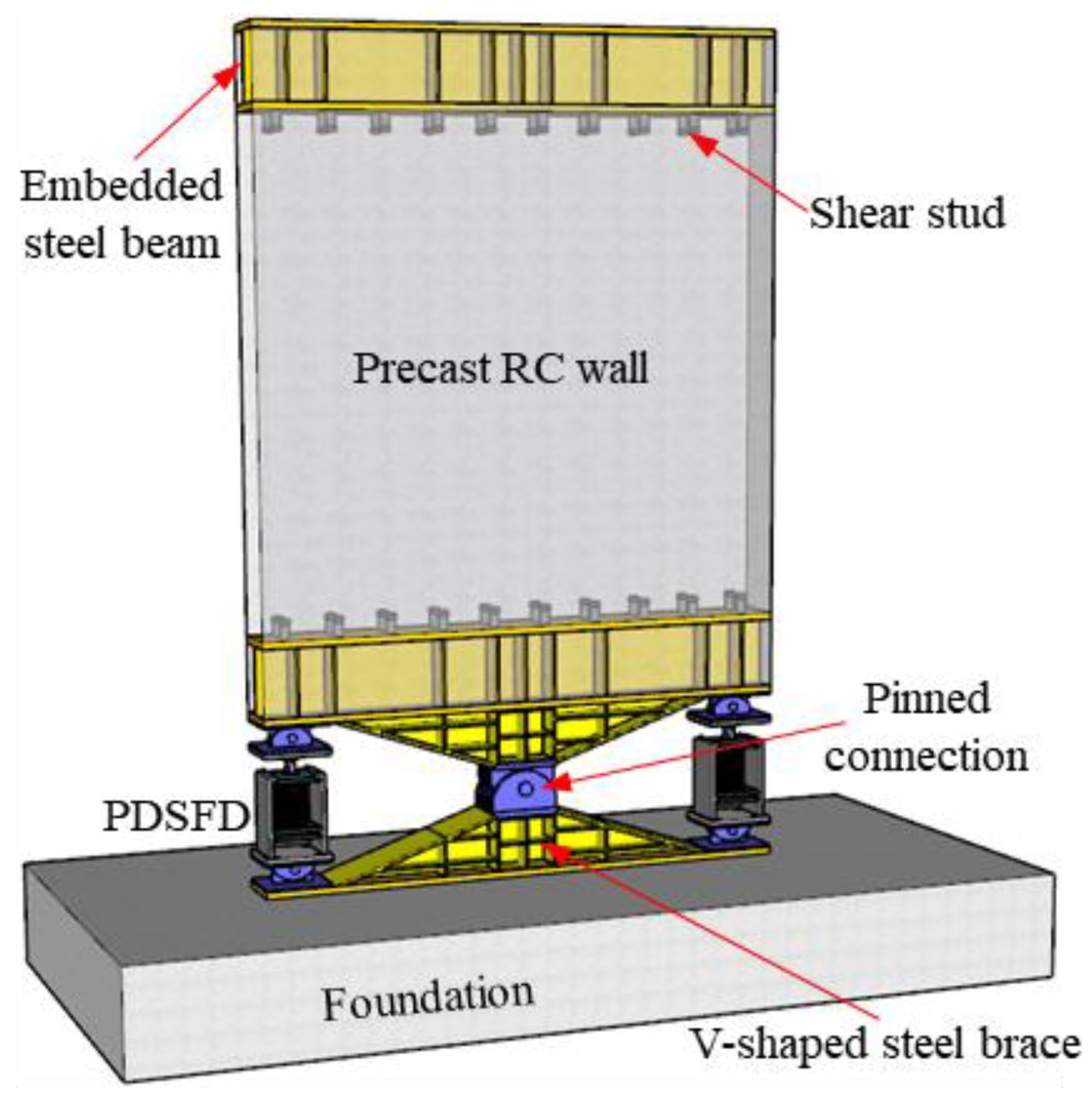
2. Proposed Precast Self-Centering Rocking Shear Wall (PSCRSW)

2.1. Description of the Details

The proposed PSCRSW is a part of the seismic resilient precast rocking shear wall innovated by the authors [25], which mainly consists of precast reinforced concrete (RC) wall, V-shaped steel brace and pre-pressed disc spring friction damper (PDSFD), as depicted in Figure 1. The precast wall is pinned by the embedded steel beam and V-shaped steel brace to the foundation or the lower wall, while two PDSFDs are, respectively, installed at two wall toes. PDSFD should be pin connected to the wall with the aim of only axial working. When lateral loading is subjected, the precast wall rocks around the pinned connection and PDSFD would be expected to provide lateral resistance, self-centering capacity and energy dissipation capacity.
Figure 2 plots the details of PDSFD, which was manufactured utilizing a prepressed disc spring, friction damper and steel plate, including shaft plate, end plates, cover plates, sliding plates and limiting plate. The disc spring and sliding plates were compressed between the limiting plates that are strengthened by steel stiffeners and fixed to the shaft plate. Six linking steel strips were adopted to bolt the cover plates that are fixed to the upper-end plate. Between the haft plate and the upper-end plate, a friction damper was placed to supply energy dissipation capacity. Once the activation force of PDSFD is exceeded by the external load, the sliding plates would be driven by the cover plates to compress the disc spring, following which elastic restoring force is generated to back PDSFD to its initial position after unloading.
The proposed PSCRSW has dual functions of bearing and energy dissipation, and most of the energy is expected to be dissipated by PDSFD. After earthquake events, the damaged PDSFD can be quickly replaced because it is decoupled from the gravity-resisting system. The number of pinned connections along the structural height can be appropriately adjusted according to the design requirement. Note that the embedded steel beam and V-shaped steel brace should be designed to equip with sufficient stiffness so that the shear force can be safely transformed.

2.2. Mechanical Behavior of the Self-Centering Energy Dissipation Device

PDSFD is the major energy dissipation member in the system while providing self-restoring force. The stress state can be described as two stages: (1) the external force is no larger than the activation force that is the sum of preload of the disc spring P0 and the friction force of the damper f0, at which the deformation is dominated by elastic behavior of the cover and shaft plates; (2) the activation force is exceeded, and thus the deformation is dominated by compression of the disc spring. The stiffness of these two stages, k1 and k2, can be expressed as Equation (1):
1 k 1 = 1 k out + 1 k int ; 1 k 2 = 1 k out + 1 k int + 1 k s
where kout and kint are the axial stiffness provided by the cover plates and the shaft plate, respectively; ks is the disc spring’s stiffness; and k2 can be approximated as ks due to the fact that kout and kint are generally much larger than ks. Based on the parallel relationship of the pre-pressed disc spring and friction damper, the hysteretic curve for PDSFD can be obtained, as shown in Figure 3. From this figure, it can be found that P0 should be designed no less than f0 to realize a desirable self-centering performance. Otherwise, residual deformation would be generated.
In order to simulate the hysteretic behavior of PDSFD, SelfCentering material and twoNodelLink elements in OpenSees can be adopted to build the numerical model, in which only four material parameters are needed, including k1, k2, P0 + f0 and 2f0/(P0 + f0). Here, the experimental data of a self-centering brace specimen composed of a pre-pressed disc spring and friction damper [23] was adopted to validate the effectiveness of the numerical model. The result comparison shown in Figure 4 illustrates that the numerical curve matches well with that of the experiment, demonstrating the reliability of the established model.

2.3. Mechanical Behavior of PSCRSW

2.3.1. Theoretical Skeleton Curve

With regarding the V-shaped steel brace and the embedded steel beam as rigid beams due to their relatively very large stiffness, the total lateral deformation of PSCRSW, Δ, can be deemed as the sum of bending shear deformation of the wall, Δw, and rocking deformation linked with PDSFD, Δs, as shown in Figure 5. Here, the wall is assumed to be elastic state during loading, and Δw can be computed as V/kc, where V is the lateral resistance, and kc is the wall’s elastic stiffness computed as Equation (2).
k c = ( h 3 c 1 3 E c I c + h c 2 G c A c ) 1
where h is the wall height; EcIc is the wall flexural stiffness and GcAc is the shear stiffness; and c1 and c2 are the corresponding modification factor associated with wall cracking, which are, respectively, suggested to be 0.25 and 0.30 [25]. According to the geometric conditions, Equation (3) can be obtained:
Δ s = a ( h + h / 2 ) c 2 sin α Δ b
where a is the height of PDSFD; h and h’ are, respectively, the height of the wall and the hinged support region; c = ( L / 2 b ) 2 + ( a / 2 ) 2 , and L and b are the wall width and the distance between the wall edge and the PDSFD center, respectively; α = arccos(1−a2/2c2); Δb is the axial deformation of PDSFD. In addition, the increment of lateral strength provided by PDSFD, ΔV, can be obtained as Equation (4) according to the moment equilibrium equation.
Δ V = Δ b k 1 or 2 ( L 2 b ) h + h / 2
Hence, the global lateral stiffness contributed by PDSFD is then given in Equation (5).
k p 1 or p 2 = Δ V Δ s = ( L 2 b ) c 2 sin α a ( h + h / 2 ) 2 k 1 or 2
where kp1 and kp2 are the stiffness contribution before and after PDSFD is activated, respectively. The lateral stiffness of PSCRSW can then be calculated as Equation (6).
K 1 or 2 = k c k p 1 or p 2 k c + k p 1 or p 2
where K1 and K2 are, respectively, the stiffness before and after PDSFD is activated. The theoretical skeleton curve for PSCRSW can then be obtained as Equation (7), in which the activation force Vy for PSCRSW equals (P0 + f0)(L − 2b)/(h + h’/2).
V = { K 1 Δ Δ V y / K 1 V y + K 2 ( Δ V y / K 1 ) Δ > V y / K 1

2.3.2. Hysteretic Behavior

In order to investigate the hysteretic behavior of PSCRSW, a specimen of a typical RC shear wall was adopted here as the prototype to be upgraded to PSCRSW [26]. Figure 6 provides the details of the prototype, which has a height of 2000 mm, a width of 1000 mm and a thickness of 125 mm. The measured concrete strength is 20.7 MPa, and the yielding strength for reinforcement with a diameter of 6 mm and 8 mm is 392 MPa and 379 MPa, respectively. The axially applied compressive load equals 246 kN, corresponding to the axial compression ratio of 0.1. In order to redesign the prototype as a PSCRSW, the fixed constraints at the bottom all need to be replaced by PDSFD and pinned connection shown in Figure 1. Because the pin-connected region can be regarded as a rigid region, the parameter design is only performed for PDSFD. During the design, two principles are followed [25]: (1) the activation displacement and force of PSCRSW are identical to the yielding displacement and strength of the prototype; (2) the designed PSCRSW has the same maximum displacement and strength as the prototype.
Figure 7 plots the hysteretic curves obtained from the experiment and numerical simulation, among which the numerical model is built by layered shell element in OpenSees [26]. The material of PlateFromPlaneStress and PlaneStressUserMaterial was adopted to model the concrete layers, and PlateRebar and steel02 material with a 0.01 strain-hardening ratio were employed to simulate the reinforcement layers. Because the numerical curve has a better symmetry, the simulation data were used here to design PDSFD. It can be obtained that the yielding strength and drift ratio are, respectively, 154.11 kN and 0.31% (6.13 mm); the averaged maximum strength of negative and positive is 179.29 kN, and the maximum drift ratio is 1.01% (20.28 mm). Assuming both a and h’ are equal to 300 mm and b equals 100 mm, then according to the design principles prescribed above, the skeleton curve of the designed PSCRSW can be determined by two V-Δ data pairs, including yield point (7.04, 154.11) and peak point (23.23, 179.29). Therefore, it can be known that Vy = 154.11 kN, K1 = 21.89 kN/mm and K2 = 1.56 kN/mm. After determining the skeleton curve, the design parameters for PDSFD can be calculated by Equation (3)~Equation (7). They are P0 + f0 = 414.17 kN, k1 = 1984.25 kN/mm, k2 = 23.97 kN/mm and Δb = 3.04 mm. Then, the dimensions of PDSFD can be obtained. Because the focus of this study is on the hysteretic behavior of PSCRSW, the PDSFD’s dimensions are not discussed here.
Based on the value of P0 + f0, six numerical cases were simulated to reveal the hysteresis behavior, which is case 1: P0 = f0, case 2: P0 = 1.5f0, case 3: P0 = 2.0f0, case 4: P0 = 2.5f0, case 5: P0 = 3.0f0, case 6: P0 = 414.7kN, f0 = 0. The numerical modeling for these cases can refer to the literature [26]. The precast wall was also modeled using a layered shell element. The pin connection region and the embedded steel beam are regarded as rigid beams. The longitudinal reinforcements in the confined region were established by adopting a truss element. The twoNodeLink element with SelfCentering material, for which the effectiveness is validated in Section 2.2, was utilized to simulate the cyclic behavior of PDSFD. The numerical analyses were performed under horizontal displacement loads that are in accordance with the experimental loading history.
Figure 8 compares the hysteretic curve between the prototype and the numerical cases, as well as the theoretical skeleton curve. As can be seen, the prototype and the numerical models have similar characteristics of the skeleton curve, and those are in good accordance with the theoretical curve, demonstrating the successful design of PSCRSW and the accuracy of theoretical derivation. The maximum forces in the negative and positive direction for all the cases are, respectively, about 172 kN and 169 kN, with an error of less than 10% compared with the design value of 179.29 kN. Moreover, it can be obviously observed that after improving with PDSFD, the hysteretic curves show a stable flag shape, resulting in significant mitigation of the residual drift. For the prototype, the maximum residual drift ratios are about 0.4% in both directions. These values were reduced to 0.17% and 0.12% in case 1, and for other cases, they were about 0.15% and 0.07%. From this comparison, it is concluded that for a ratio of p0 to f0, no less than 1.5 can ensure excellent self-centering performance.
Figure 9 compares the hysteretic curves corresponding to the part of the RC wall. It is evident that the deformation experienced by the wall in PSCRSW is much smaller than that of the prototype, while the maximum bearing capacities between them are approximate. That is, the wall in PSCRSW dissipates less energy and develops lower plasticity. Table 1 summarizes the energy dissipation of the numerical models. With an increase in p0/f0, the energy dissipated by PSCRSW gradually decreases as a result of the diminishing friction force of the damper. When p0/f0 does not exceed 2.0, the energy dissipation capacity of PSCRSW is better than the prototype, and in these cases, PDSFD dissipates about 70% of the total energy. The energy dissipations of the RC wall in PSCRSW range from 7.42 kJ to 7.54 kJ, which are more than 60% less than that of the prototype, indicating that after improving with PDSFD, the plastic wall damage is significantly mitigated. By combining the analysis of Figure 8, it is recommended that the value of p0/f0 adopts 1.5~2.0 during the design.
The above PSCRSW is designed based on the principle of equivalent yielding and bearing performance. Although it shows much better seismic performance than the prototype, the wall in it still exhibits obvious nonlinear behavior, and the residual drift is still noticeable. For further investigation, numerical analyses for the PSCRSW model with yielding strength (or p0 + f0) reduced were conducted, and the results are displayed in Figure 10. As can be seen, when the reduced factor is 0.9, the strength is slightly decreased while the residual drift is obviously reduced. When the reduced factor is 0.8, the maximum strengths for both two cases are decreased from 172 kN to 149 kN in a positive direction and from 169 kN to 148 kN in a negative direction, with degradation within 15%, while the residual drifts are greatly reduced. Generally, the reduction in yielding strength can significantly reduce the residual drift with a slight sacrifice of bearing capacity. Therefore, we can amplify the bearing capacity about 1.2 times for the RC wall during the design to ensure the bearing performance and a better self-centering performance simultaneously.

3. Enhancing Strategy and Design Procedure

The presented PSCRSW is capable of supplying load bearing, energy dissipation and self-centering capabilities for seismic resilient application. When used to enhance the seismic resilience of SMRF, it can be adopted as an externally installed rocking wall and internally installed cladding panel or infilled wall. The focus of this study was on the former, as plotted in Figure 11. It should be noted that the number and locations of pinned connections along the structural height can be adjusted according to the design requirement. In order to realize the expected performance objectives of enhancement, an effective design method is necessary. At present, the relevant methods generally need many iterations of nonlinear dynamic calculation. For the purpose of achieving fast and efficient design, a new procedure was proposed, and the design steps are outlined as follows:
(1)
Specify the performance objectives and the corresponding inter-story drift ratio (ISDR) targets, which are denoted as θy, θd and θu for service level earthquake (SLE), design-based earthquake (DBE) and maximum considered earthquake (MCE), respectively.
(2)
Establish a numerical model for the prototype needed enhancement and conduct nonlinear dynamic analysis under excitation of SLE, DBE and MCE levels. Then, assess whether its seismic performance meets the preselected targets. If not, it should be enhanced through the following steps.
(3)
Fitting the mathematical relationship between the maximum ISDR and roof drift ratio based on the results obtained from step (2), and convert the ISDR targets in step (1) into the roof drift ratio targets θr,y, θr,d and θr,u.
(4)
Estimate the fundamental period of the enhanced SMRF. The roof drift demand of an equivalent single degree of freedom (SDOF) system, also called the spectral displacement Sd, can be calculated by Equation (8):
S d = θ r , y H / C 0
where H is the structural height; C0 is the adjusted coefficient for roof drift of multiple DOF system transforming to that of the SDOF. By combining with the target spectrum specified in the design code, the fundamental period T can be determined.
(5)
Select the distribution pattern of lateral force. In this study, the pattern presented by Chao [27] through extensive nonlinear dynamic analyses was employed during the design, which is expressed as Equation (9):
F i = C i V ;   C i = ( β i β i + 1 ) ( w n h n j = 1 n w j h j ) p T 0.2 ;   β i = V i V n = ( j = i n w j h j w n h n ) p T 0.2
where Fi is the lateral force at the ith floor; Ci is the lateral force distribution factor; V is the base shear; βi is the shear force factor; Vi and Vn are story force at ith and top floor, respectively; wi and wn are weight for ith and top floor, respectively; hi and hn are the height from ith and top floor to the base, respectively; the parameter P is suggested as 0.75 to considering the effect of a higher modal response.
(6)
Calculate the design value of the base shear for the enhanced SMRF, Vy. Here a widely used method named performance-based plastic design was adopted to calculate Vy. This method regards the force–displacement curve of the structure as an ideal bilinear model and obtains the base shear based on the energy equivalent concept. The specific derivation can refer to the literature [15], and the base shear Vy is expressed as Equation (10).
V y W = ω + ω 2 + 4 γ ( S a / g ) 2 2 ;   ω = 8 θ p π 2 T 2 g i = 1 n C i h i
where W and g are, respectively, the total structure weight and the gravity constant, and θp is the plastic drift ratio; at DBE and MCE levels they are, respectively, θr,dθr,y and θr,uθr,y, and the plastic drift ratios for all the floors are assumed as the same; γ is the energy modification factor, which can be determined according to the structural period T and ductility factor μs [15]. For DBE and MCE levels, μs is, respectively, equal to θr,d/θr,y and θr,u/θr,y. By combining the value of design spectral acceleration Sa of DBE and MCE, the corresponding base shear can be calculated, which is denoted as Vy,d and Vy,u. Equation (11) gives the finally determined design base shear:
V y = max ( S a 1 W ,   V y , d ,   V y , u )
where Sa1 is the design spectral acceleration at the SLE level.
(7)
Determine the seismic demand of PSCRSW. Firstly, simplify the lateral force as an inverted triangle load, q, based on the moment equivalent principle, Vy and Ci, and regard the enhanced SMRF as a traditional frame-shear wall structure. Then, the lateral displacement of the structure can be calculated by Equation (12):
u = q H 4 λ 2 E c I e q [ ( 1 + λ sh λ 2 sh λ λ ) ch λ ξ 1 λ 2 ch λ + ( 1 2 1 λ 2 ) ( ξ sh λ ξ λ ) ξ 2 6 ]
where ξ = x/H, and x is the height of any floor; λ is the eigenvalue of the stiffness and equals H C F / ( E c I e q ) ; CF is the shear stiffness of the frame, which can be determined from pushover analysis of the prototype SMRF; EcIeq is the bending stiffness of RC shear wall.
Secondly, substitute the target roof drift θr,yH into Equation (12) and solve the value of λ. Then, the bending stiffness EcIeq can be obtained. Moreover, the moment and shear demands can be calculated by Equations (13) and (14). Subsequently, the parameters of the wall can be designed.
M w = q H 2 λ 2 [ ( 1 + λ sh λ 2 sh λ λ ) ch λ ξ ch λ ( λ 2 1 λ ) sh λ ξ ζ ]
Q w = q H λ 2 [ ( 1 + λ sh λ 2 sh λ λ ) λ sh λ ξ ch λ ( λ 2 1 λ ) λ ch λ ξ 1 ]
(8)
Determine the parameters of PDSFD according to the design principles presented in Section 2.3.
(9)
Establish a numerical model for the enhanced SMRF and check the fundamental period T. If T converges to the final design value, perform nonlinear dynamic analysis to assess the structural seismic performance. Otherwise, return to step 5 for iteration.

4. Case Study

4.1. Prototype Building

A typical 9-story SMRF was adopted as the prototype to be enhanced, which was firstly designed for the SAC project as the benchmark model and is widely chosen to assess the performance of seismic enhancing strategy [28,29]. The prototype assumes to be located in Los Angels with site class C, and there are five bays with a width of 9.15 m in each direction of the building. Only one lateral resisting frame was investigated in this study due to the structural symmetry. Figure 12 shows the elevation view of the selected frame and the design information of the members. The height of the standard floor was 3.96 m, and for the basement and first floor, they were 3.65 m and 5.49 m, respectively. All the members were manufactured using W-section steel, with nominal yielding strength of 248 MPa for the beams and 345 MPa for the columns. The columns were pin-connected to the base. The tributary seismic mass of the chosen lateral resisting frame was 4.50 × 10⁶ kg.

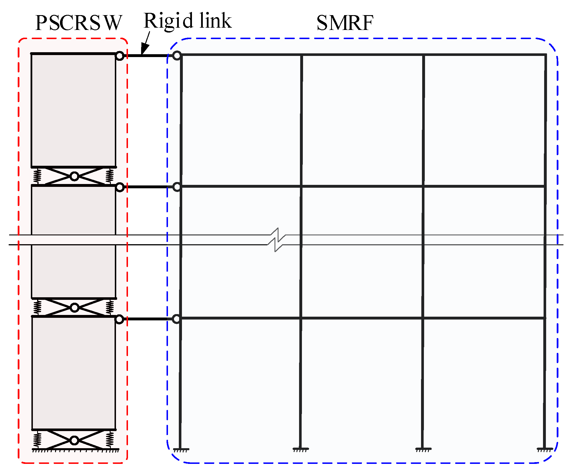
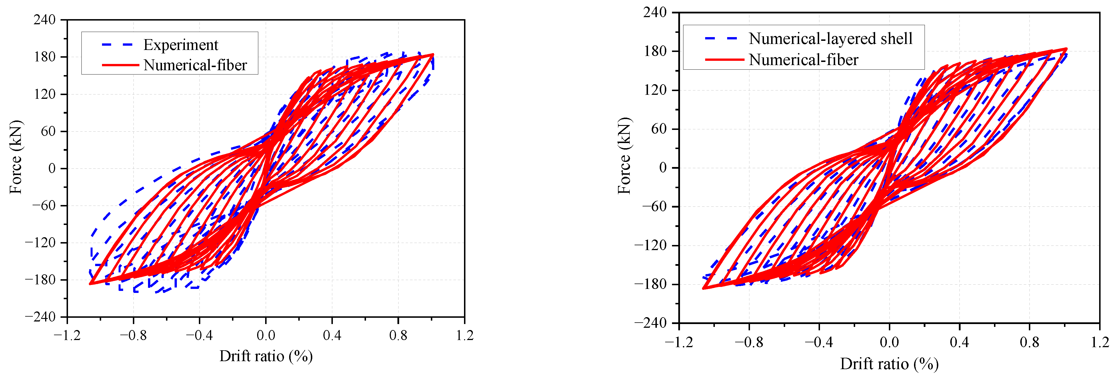
4.2. Numerical Modelling

Numerical analysis is an important approach to assess the performance of engineering structures under seismic excitations, the effectiveness of which has been verified in many previous studies, such as for seismic assessment of steel geodesic dome [30], slope effect on soil–pile interaction [31] and modular precast composite shear wall [32]. In this study, numerical analysis was also adopted to assess the seismic performance of SMRF before and after enhancement, as well as the effectiveness of the presented design method.
Numerical models for the prototype and enhanced SMRF were built using the OpenSees program in this section. The beam and column members were modeled using an elastic beam–column element with two concentrated plastic hinges located at the ends. In order to capture the deterioration behavior of stiffness and strength of the members, zero-length rotational springs with the modified Ibarra–Medina–Krawinkler (IMK) deterioration material that is calibrated by a lot of experimental data [33] were utilized for simulating the nonlinear properties of the hinges. The panel zone of beam-to-column joints was modeled through the approach specified in ATC 72-1 [34], which includes eight rigid beam–column elements, three pinned connections and one rotational spring. A trilinear hysteretic model presented by Gupta and Krawinkler [35] was incorporated into the rotational spring to account for the shear distortion effect. The P-Δ effect was also considered in the numerical model by a leaning column that is built through a zero-length rotational spring with very small stiffness and rigid beam–column elements. The modeling of PSCRSW adopted a similar approach as illustrated in Section 2.3. The only difference between them is that the RC wall is modeled using a beam–column element with a fiber section instead of a layered shell element. Each story wall was divided into four elements, and each element was assigned five integration points. Rigid links were established to connect the steel frame and PSCRSW. The detailed numerical model can be seen in Figure 13. Figure 14 compares the hysteretic curve of the wall specimen in Section 2.3, simulated by fiber beam–column element, with that of the experiment and layered shell element-simulated model. As can be seen, the results are in good agreement with each other, indicating the effectiveness of the numerical model for PSCRSW.

4.3. Enhancing Design

The targets of ISDR for SLE, DBE and MCE levels were adopted as θy = 0.4%, θd = 1.5% and θu = 2.0% in this study, respectively. According to design step (3), the relationship between the inter-story and roof drift ratios was fitted based on the dynamic responses of the prototype under the excitation of earthquake records shown in Section 4.4. The fitting results are provided in Figure 15, by which the targets of roof drift ratio can be obtained as 0.25%, 0.94% and 1.25% for each seismic level. Then, other critical design parameters can be calculated according to design steps (4)~(6), as listed in Table 2. The finally determined design base shear equaled 0.17W. The final period was 1.30 s, which converged to the initial design value of 1.34 s. It should be noted that the design was finished using one loop without iteration performed.
After determining the base shear, the parameters in design step (7) could be calculated, including q = 543.8 kN/m, CF = 7.53 × 10⁵ kN, λ = 1.25, Ieq = 22.2 m4. The material properties of the concrete and reinforcement were assumed to be the same, as shown in Figure 6. The elastic modulus of concrete was Ec = 3 × 10⁴ MPa. Then, the dimensions of the wall section were computed as L = 6.0 m, t = 1.2m, and the width of confined regions was selected as 0.8 m. For the walls in 1~3 story, 16 longitudinal reinforcements with a diameter of 32 mm were placed in each confined region, and 36 vertical distribution reinforcements with a diameter of 28 mm were placed in the non-confined region. For walls in other stories, the numbers of reinforcements were the same, but the diameters for them were 25 mm and 20 mm in 4~6 stories and 20 mm and 18 mm in 7~9 stories. The strategy with one pinned connection located at the bottom was adopted, and optimization of the locations and numbers of pinned connections along the structural height was not discussed in this study. The geometric parameters were assumed as a = h’ = 2.0 m and b = 0.3 m. The value of p0 + f0, k1 and k2 for PDSFD were calculated as 2.82 × 10⁴ kN, 4.18 × 10³ kN/mm and 2.09 × 10² kN/mm, respectively.

4.4. Seismic Performance Assessment

In order to assess the seismic performance of the prototype and enhanced SMRF, nonlinear time history analyses were performed under the excitation of earthquake records listed in Table 3. There was a total of 12 records that were selected on the basis of site class and design spectrum in ASCE 7–10 [7]. The spectral design parameters for the DBE level, SDS and SD1, were 1.6 and 0.74, and for the MCE level, SMS and SM1, were 2.4 and 1.1, respectively. The peak ground accelerations for SLE, DBE and MCE levels were, respectively, 0.16 g, 0.64 g and 0.96 g. The equivalent shear wave velocity Vs30 ranged from 366 km/s to 762 km/s during the record selection, the magnitude ranges were 6~8, and the fault distance ranges were 0~10 km. Figure 16 plots the response spectrum of the earthquake records and the design spectrum. These records were selected and associated with the first three vibration periods (2.05 s, 0.78 s and 0.43 s) of the chosen SMRF. As can be seen, the mean spectrum agrees well with the target spectrum when the period exceeds 0.43 s, within a 10% relative error. Because the seismic response of the SMRF was dominated by the first three vibration modes, the short periods were not considered during the record selection, and the corresponding mean spectrum was much stronger. During the analysis, each record was extended by 10 s of free vibration to capture the residual drift accurately.
Figure 17 shows the story-wise distribution of the inter-story drift ratio (ISDR) of the prototype and enhanced SMRF. The maximum mean ISDRs of the prototype were 0.50%, 1.64% and 2.30% for SLE, DBE and MCE levels, respectively, which are larger than the design targets of 0.4%, 1.5% and 2.0%, indicating that the design requirements were not met, and the seismic performance needs to be enhanced. After being enhanced, the maximum mean ISDRs were, respectively, reduced to 0.38%, 1.32% and 1.99%, which are approximate to the design targets. Figure 18 compares the roof drift ratios between the analytical values and the targets. The mean roof drift ratios for SLE, DBE and MCE levels were, respectively, 0.25%, 0.89% and 1.31%. The errors between these values and the targets are about 0%, 5% and 5%, respectively. In general, the enhanced SMRF is not only capable of achieving the ISDR targets of multiple seismic hazard levels but also the roof drift ratio targets, demonstrating the effectiveness of the enhanced SMRF, realizing the expected seismic performance objectives and of the proposed design procedure.
Figure 19 compares the roof drift time history curves of the prototype and the enhanced SMRF, taking the responses of earthquakes GM4 (with the maximum response) and GM5 (with the minimum response) as an example. Under the excitation of GM4, the peak roof drifts are reduced by enhancing from 228 mm, 574 mm and 867 mm to 122 mm, 383 mm and 687 mm, respectively, for SLE, DBE and MCE levels, while the residual drifts are reduced from 1.12 mm, 200 mm and 461 mm to 0.02 mm, 13 mm and 210 mm. Under the excitation of GM5, the peak roof drifts decrease from 115 mm, 336 mm and 594 mm to 49 mm, 201 mm and 326 mm, while the residual drifts decrease from 0.5 mm, 22.2 mm and 72.6 mm to 0 mm, 1.3 mm and 2.1 mm. These results show that the dynamic responses can be significantly mitigated by the presented PSCRSW. Moreover, the maximum residual inter-story drift ratios before and after enhancement are compared in Figure 20. As can be seen, the residual inter-story drift ratios are obviously decreased by enhancing overall. The mean degradation of all the earthquake records is about 54%, indicating that the structural recoverability post-earthquakes would be improved.
Table 4 analyzes the effect of PSCRSW on the structural performance from the perspective of energy dissipation, in which the energy dissipated by the beam and column hinges were compared. For all the records, both the energy dissipated by beams and columns was significantly reduced, with the total energy, respectively, decreased by 58% and 99%. Therefore, it can be concluded that the damages that occurred in beams and columns are significantly mitigated, which further illustrates the effectiveness of PSCRSW in enhancing structural seismic resilience.
The above analyses compared the structural performance between the prototype and the enhanced SMRF based on the dynamic responses and energy dissipation. However, there is a lack of comparison to other similar studies. In previous studies, the enhancing strategies generally have little effect on the story-wise distribution tendency of the inter-story drift ratio, and the weak story usually appears in the bottom or middle part of the structure [1,2,11,15,17]. From Figure 17, it can be observed that the enhancement in this study has a better seismic mitigation effect on the bottom and middle stories, and the weak story occurs at the top of the structure, indicating that the repair of structural damages would be less difficult. In addition, the design procedures in previous studies generally require many iterations of nonlinear dynamic analysis and are unable to take the targets of inter-story drift and roof drift ratios into account simultaneously [2,13,15,17]. The results of this study show that the presented design procedure successfully makes up for these deficiencies. The convergence of enhancing design for SMRF with PSCRSW in this research was achieved without performing iteration, and the inter-story drift and roof drift targets were realized. The presented design framework can be extended to SMRF with other enhancing strategies.

5. Conclusions

By theoretical and numerical analyses, the effectiveness of the presented PSCRSW and the design method for enhancing the seismic resilience of SMRF were validated, and the main conclusions and suggestions were obtained:
  • PSCRSW can realize approximate yielding behavior, displacement capacity and lateral strength to the prototype (conventional RC shear wall) while exhibiting a stable flag shape hysteretic curve. In order to ensure excellent self-centering performance, the ratio of preload P0 to friction force f0 of PSCRSW is suggested to be no less than 1.5;
  • When the ratio of P0 to f0 does not exceed 2.0, PSCRSW shows obviously better energy dissipation capacity than the prototype, and about 70% of the energy is dissipated by PDSFD. Moreover, the energy dissipated by the RC wall in PSCRSW is more than 60% less than that of the prototype, which indicates that the plastic damage of the wall in PSCRSW is much lower;
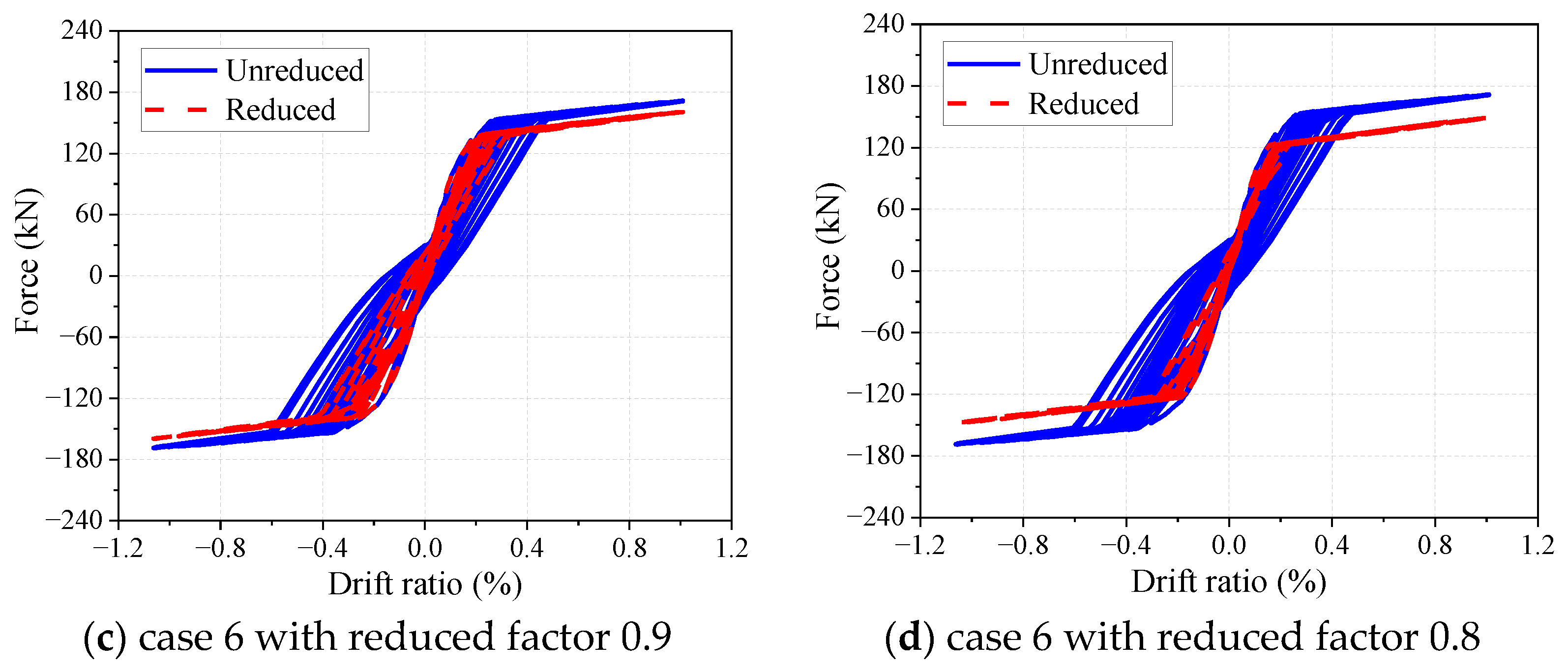
  • During the design of PSCRSW, the amplification factor of 1.2 should be considered for the bearing capacity of the RC wall, at which not only the bearing performance but also the self-centering performance can be ensured;
  • By the proposed design method, the enhanced SMRF achieves the inter-story drift ratio targets, and the expected roof drift ratios simultaneously. No iteration is conducted during the enhancement design;
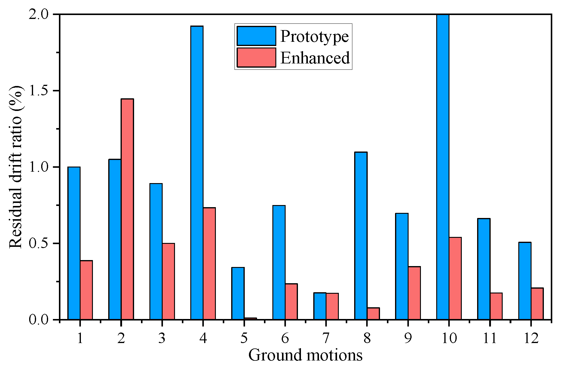
  • The seismic responses of the SMRF are significantly reduced after enhancement. The mean degradation of residual inter-story drift ratios is about 54%, and the total energy dissipated by the beams and columns is, respectively, decreased by 58% and 99%, demonstrating that the seismic resilience of SMRF is effectively enhanced by PSCRSW.

Author Contributions

Conceptualization, Z.Z. and W.G.; methodology, Z.Z.; software, Z.Z.; validation, Z.Z. and S.Z.; formal analysis, Z.Z.; investigation, Z.Z.; resources, Z.Z.; data curation, Z.Z.; writing—original draft preparation, Z.Z.; writing—review and editing, S.Z., W.G. and Y.L.; visualization, S.Z.; supervision, F.Z.; project administration, Y.L.; funding acquisition, Z.Z. All authors have read and agreed to the published version of the manuscript.

Funding

This research was funded by [the fellowship of China Postdoctoral Science Foundation] grant number [2022M710871], [the Postdoctoral Program of International Training Program for Young Talents in Guangdong Province] grant number [N/A], [the National Key R&D Project of China] grant numbe [No.2021YFE0112200], [the Guangdong Provincial Key Laboratory of Earthquake Engineering and Applied Technology] grant number [2020B1212060071]. And The APC was funded by [the fellowship of China Postdoctoral Science Foundation, No.2022M710871].

Data Availability Statement

Data is contained within the article.

Acknowledgments

The authors are grateful for the financial support from the fellowship of China Postdoctoral Science Foundation (No.2022M710871), the Postdoctoral Program of International Training Program for Young Talents in Guangdong Province, the National Key R&D Project of China (No.2021YFE0112200) and the Guangdong Provincial Key Laboratory of Earthquake Engineering and Applied Technology (Project No.2020B1212060071).

Conflicts of Interest

The authors declare no conflict of interest.

References

  1. Zhou, Z.; Ke, K.; Chen, Y.; Yam, M.C. High strength steel frames with curved knee braces: Performance-based damage-control design framework. J. Constr. Steel Res. 2022, 196, 107392. [Google Scholar] [CrossRef]
  2. Zhai, Z.; Li, S.; Liu, Y.; Ma, Y.; Zou, S.; Zhou, F. Seismic retrofitting of SMRFs using varied yielding cross-section damper: A companion paper. J. Constr. Steel Res. 2022, 194, 107290. [Google Scholar] [CrossRef]
  3. Chu, G.; Wang, W.; Zhang, Y. Nonlinear seismic performance of beam-through steel frames with self-centering modular panel and replaceable hysteretic dampers. J. Constr. Steel Res. 2020, 170, 106091. [Google Scholar] [CrossRef]
  4. Wang, Y.; Zhou, Z.; Ge, H.; Yao, J.; Xie, Q. Experimental validation and numerical simulation of a dual-self-centering variable friction braced frame under strong ground motions. J. Build. Eng. 2022, 56, 104761. [Google Scholar] [CrossRef]
  5. Pieroni, L.; Di Benedetto, S.; Freddi, F.; Latour, M. Genetic Algorithm for the optimal placement of Self-Centering Damage-Free joints in steel MRFs. J. Constr. Steel Res. 2022, 197, 107489. [Google Scholar] [CrossRef]
  6. Miller, D.K. Lessons learned from the Northridge earthquake. Eng. Struct. 1998, 20, 249–260. [Google Scholar] [CrossRef]
  7. ASCE 7-10; Minimum Design Loads for Buildings and Other Structures. American Society of Civil Engineers (ASCE): Reston, VA, USA, 2010.
  8. National Building Code of Canada (NBCC). Division B Part 4 Structural Design; NBCC: Ottawa, ON, Canada, 2005.
  9. GB 50011-2010; Code for Seismic Design of Buildings. China Architecture & Building Press: Beijing, China, 2010. (In Chinese)
  10. He, X.; Chen, Y.; Ke, K.; Shao, T.; Yam, M.C. Development of a connection equipped with fuse angles for steel moment resisting frames. Eng. Struct. 2022, 265, 114503. [Google Scholar] [CrossRef]
  11. Zhai, Z.; Guo, W.; Yu, Z.; Hu, Y.; Ma, C. Seismic performance assessment of steel strip dampers equipped in high rise steel frame. J. Constr. Steel Res. 2021, 177, 106437. [Google Scholar] [CrossRef]
  12. Zhai, Z.; Guo, W.; Chen, W.; Yu, Z.; Zeng, C.; Li, S. Effect of damper failure on the seismic loss assessment of retrofitted steel moment resisting frames. Soil Dyn. Earthq. Eng. 2021, 150, 106903. [Google Scholar] [CrossRef]
  13. He, J.; Lin, S.; Li, Y.; Dong, X.; Chen, S. Genetic Algorithm for Optimal Placement of Steel Plate Shear Walls for Steel Frames. Buildings 2022, 12, 835. [Google Scholar] [CrossRef]
  14. Bae, J.; Kim, Y.-J.; Lee, C.-H. Improving the Seismic Performance of Tall Steel Buildings Using Advanced Visco-Plastic Braces. Int. J. Steel Struct. 2022. [Google Scholar] [CrossRef]
  15. Zhai, Z.; Guo, W.; Li, Y.; Yu, Z.; Cao, H.; Bu, D. An improved performance-based plastic design method for seismic resilient fused high-rise buildings. Eng. Struct. 2019, 199, 109650. [Google Scholar] [CrossRef]
  16. Zhou, X.; Sun, T.; Sun, B.; Ma, N.; Ou, J. Vibration-Reduction Strategy for High-Rise Braced Frame Using Viscoelastic-Yielding Compounded BRB. Buildings 2022, 12, 1159. [Google Scholar] [CrossRef]
  17. Qiu, C.; Jiang, T.; Liu, J.; Du, X. Seismic performance of knee-braced frames equipped with NiTi BRBs. J. Constr. Steel Res. 2022, 197, 107480. [Google Scholar] [CrossRef]
  18. Grigorian, M.; Moghadam, A.S.; Mohammadi, H.; Kamizi, M. Methodology for developing earthquake-resilient structures. Struct. Des. Tall Speéc. Build. 2018, 28, e157. [Google Scholar] [CrossRef]
  19. Garlock, M.; Rides, J.; Sause, R. Experimental studies of full-scale posttensioned steel connections. J. Struct. Eng. 2005, 131, 438–448. [Google Scholar] [CrossRef]
  20. Garlock, M.M.; Ricles, J.M.; Sause, R. Influence of design parameters on seismic response of post-tensioned steel MRF systems. Eng. Struct. 2007, 30, 1037–1047. [Google Scholar] [CrossRef]
  21. Zhongwei, Z.; Xiangyang, J.; Ye, Y.; Haiqing, L. Optimization for friction damped post-tensioned steel frame based on simplified FE model and GA. Earthq. Eng. Eng. Vib. 2022, 21, 209–219. [Google Scholar] [CrossRef]
  22. Henry, R.; Zhou, Y.; Lu, Y. Shake-table test of a two-storey low-damage concrete wall building. Earthq. Eng. Struct. Dynam. 2021, 50, 3160–3183. [Google Scholar] [CrossRef]
  23. Xu, L.; Yao, S.; Sun, Y. Development and validation tests of an assembly self-centering energy dissipation brace. Soil Dyn. Earthq. Eng. 2018, 116, 120–129. [Google Scholar] [CrossRef]
  24. Zhang, G.; Xu, L.-H.; Li, Z.-X. Development and seismic retrofit of an innovative modular steel structure connection using symmetrical self-centering haunch braces. Eng. Struct. 2020, 229, 111671. [Google Scholar] [CrossRef]
  25. Zhai, Z.; Liu, Y.; Guo, W.; Chen, F.; Yu, Z.; Zhou, F. Seismic resilient rocking shear wall with dual self-centering energy dissipation system: Introduction and A preliminary study. J. Build. Eng. 2022, 61, 105271. [Google Scholar] [CrossRef]
  26. Zhai, Z.; Guo, W.; Liu, Y.; Ma, Y.; Zhou, F. New precast self-centering rocking shear wall with multiple hinged joints: Description and design approach for seismic protection of buildings. Eng. Struct. 2022, 262, 114401. [Google Scholar] [CrossRef]
  27. Chao, S.H.; Goel, S.C.; Lee, S.S. A seismic design lateral force distribution based on inelastic state of structures. Earthq. Spectra 2007, 23, 547–569. [Google Scholar] [CrossRef] [Green Version]
  28. Guo, W.; Hu, Y.; Li, Y.; Zhai, Z.; Shao, P. Seismic performance evaluation of typical dampers designed by Chinese Code subjected to the main shock-aftershocks. Soil Dyn. Earthq. Eng. 2019, 126, 105829. [Google Scholar] [CrossRef]
  29. Ohtori, Y.; Christenson, R.E.; Spencer, B.F., Jr.; Dyke, S.J. Benchmark Control Problems for Seismically Excited Nonlinear Buildings. J. Eng. Mech. 2004, 130, 366–385. [Google Scholar] [CrossRef] [Green Version]
  30. Pilarska, D.; Maleska, T. Numerical analysis of steel geodesic dome under seismic excitations. Materials 2021, 14, 4493. [Google Scholar] [CrossRef]
  31. Tran, N.X.; Gu, K.-Y.; Yoo, M.; Kim, S.-R. Numerical evaluation of slope effect on soil–pile interaction in seismic analysis. Appl. Ocean Res. 2022, 126, 103291. [Google Scholar] [CrossRef]
  32. Wu, D.; Jiang, D.; Zhao, B. Nonlinear numerical modeling approach and seismic mechanism analysis on new modular precast composite shear wall structure. Eng. Struct. 2022, 270, 114868. [Google Scholar] [CrossRef]
  33. Lignos, D.G.; Krawinkler, H. Deterioration Modeling of Steel Components in Support of Collapse Prediction of Steel Moment Frames under Earthquake Loading. J. Struct. Eng. 2011, 137, 1291–1302. [Google Scholar] [CrossRef]
  34. PEER/ATC 72-1; Modeling and Acceptance Criteria for Seismic Design and Analysis of Tall Buildings. Applied Technology Council: Redwood, CA, USA, 2010.
  35. Gupta, A.; Krawinkler, H. Seismic Demands for Performance Evaluation of Steel Moment Resisting Frame Structures; Technical Report 132; The John A. Blume Earthquake Engineering Research Center, Department of Civil Engineering, Stanford University: Stanford, CA, USA, 1999. [Google Scholar]
Figure 1. Schematic diagram of the presented PSCRSW.
Buildings 12 01957 g001
Figure 2. Schematic diagram of PDSFD.
Buildings 12 01957 g002
Figure 3. Hysteretic curve of PDSFD.
Buildings 12 01957 g003
Figure 4. Numerical validation of PDSFD.
Buildings 12 01957 g004
Figure 5. Deformation mode of PSCRSW. (a) Bending shear deformation of the wall. (b) Rocking deformation.
Buildings 12 01957 g005
Figure 6. Details of the prototype specimen (unit: mm) [26].
Buildings 12 01957 g006
Figure 7. Hysteretic curves of the prototype specimen [26].
Buildings 12 01957 g007
Figure 8. Hysteretic curve of the numerical cases.
Buildings 12 01957 g008
Figure 9. Hysteretic curve of the wall in numerical models.
Buildings 12 01957 g009aBuildings 12 01957 g009b
Figure 10. Hysteretic curve of the numerical models with reduced yielding strength.
Buildings 12 01957 g010aBuildings 12 01957 g010b
Figure 11. Enhancing strategy for SMRF.
Buildings 12 01957 g011
Figure 12. The prototype building.
Buildings 12 01957 g012
Figure 13. Numerical modeling for PSCRSW.
Buildings 12 01957 g013
Figure 14. Hysteretic curve of the wall specimen simulated by fiber element.
Buildings 12 01957 g014
Figure 15. Fitting relationship between inter-story and roof drift ratios.
Buildings 12 01957 g015
Figure 16. Response spectra of the earthquake records scaled to DBE level.
Buildings 12 01957 g016
Figure 17. Inter-story drift ratio of the prototype and the enhanced SMRF.
Buildings 12 01957 g017
Figure 18. Comparison of the analytical and designed roof drift ratios.
Buildings 12 01957 g018
Figure 19. Comparison of the roof drift time history curves.
Buildings 12 01957 g019aBuildings 12 01957 g019b
Figure 20. Comparison of the maximum residual inter-story drift ratios.
Buildings 12 01957 g020
Table 1. Energy dissipation of the numerical models (unit: kJ).
ModelsTotal EnergyDissipated by PDSFDDissipated by Wall
EnergyProportionEnergyProportion
Prototype19.90--19.90100%
Case 127.4819.9472.5%7.5427.5%
Case 223.4815.6068.1%7.4831.9%
Case 320.8013.3664.2%7.4435.8%
Case 418.8511.4260.6%7.4339.4%
Case 517.4310.0057.4%7.4342.6%
Case 67.440.040.5%7.4299.7%
Table 2. Design parameters in the design method.
ParametersSLEDBEMCE
T/s1.341.341.34
Sa/g0.140.550.83
θy θd θu0.4%1.5%2.0%
θr,yθr,dθr,u0.25%0.9375%1.25%
θp00.6875%1.0%
μs13.755
C01.481.481.48
γ1.00.470.36
Vy/W0.140.140.17
Table 3. Earthquake records.
No.EarthquakeYearMagnitudeNGA#StationFault Distance (km)
GM1Loma Prieta19896.93802Saratoga—Aloha Ave8.50
GM2Cape Mendocino19927.01825Cape Mendocino6.96
GM3Chi-Chi_ Taiwan19997.621493TCU0535.95
GM4Chi-Chi_ Taiwan19997.621504TCU0670.62
GM5Chi-Chi_ Taiwan19997.621511TCU762.74
GM6Chi-Chi_ Taiwan19997.621521TCU899.00
GM7Chi-Chi_ Taiwan19997.621546TCU1229.34
GM8Chi-Chi_ Taiwan19997.621551TCU1389.78
GM9Tottori_ Japan20006.613947SMNH015.86
GM10Tottori_ Japan20006.613966TTR0098.83
GM11Iwate_ Japan20086.905658IWTH266.02
GM12Christchurch_ New Zealand20116.208158LPCC6.12
Table 4. The comparison of energy dissipated by the frame members.
No. of EarthquakesPrototype FrameEnhanced Frame1 − EB2/EB11 − EC2/EC1
Beam Hinges
EB1 (kJ)
Column Hinges
EC1 (kJ)
Beam Hinges
EB2 (kJ)
Column Hinges
EC2 (kJ)
14301.018.83150.40.1127%99%
22874.418.11440.00.8350%95%
33143.40.481201.70.2562%48%
48589.57.824613.90.3546%96%
53884.40.155793.90.0185%97%
67124.00.332181.80.0569%85%
72037.40.074540.70.0678%10%
84604.40.323601.40.0422%88%
95019.314.51137.30.1577%99%
105629.4189.61548.70.2972%100%
114557.10.607367.80.1084%83%
123121.70.242212.00.1829%25%
Total54,886.1251.122,857.62.4358%99%
Publisher’s Note: MDPI stays neutral with regard to jurisdictional claims in published maps and institutional affiliations.

