Article

Full-Scale Test and Bearing Capacity Evaluation of Large Diameter Prestressed Concrete Cylinder Pipe under Internal Water Pressure

1
International Joint Research Lab for Eco-Building Materials and Engineering of Henan, North China University of Water Resources and Electric Power, Zhengzhou 450045, China
2
Henan Fuchen Pipe Co., Ltd., Xinxiang 453400, China
3
Collaborative Innovation Center for Efficient Utilization of Water Resources, North China University of Water Resources and Electric Power, Zhengzhou 450046, China
*
Author to whom correspondence should be addressed.
Buildings 2022, 12(11), 1791; https://doi.org/10.3390/buildings12111791
Submission received: 5 October 2022 / Revised: 20 October 2022 / Accepted: 24 October 2022 / Published: 26 October 2022
(This article belongs to the Topic Pipeline and Underground Space Technology)

Abstract

:
In practical applications, the safe operation of large-diameter prestressed concrete cylinder pipes (PCCPs) depends on the loading performance under internal water pressure. However, there is lack of damage tests for the full-scale large-diameter PCCPs due to economic cost and experimental difficulty. In this paper, a full-scale PCCP with diameter of 3.2 m was tested to verify the bearing capacity for applying to an actual water transfer project. The PCCP was designed by the limit state method and manufactured in a prefabrication plant. During the test, the strains of concrete, prestressed steel wire, and mortar were detected to evaluate the limit state of bearing capacity under internal water pressure. Based on the test results and the strain analysis at the limit state, it was found that when the water pressure reached 1.9 MPa, the concrete outside the steel cylinder was at the serviceability limit state, and the prestressed steel wire was in elastic, while some protective mortar exceeded the serviceability limit state due to the appearance of visible cracks. A good accuracy of the theoretical calculation with the predicted results lower about 9.4% and 8% than tested pressures at decompression and cracking states. Moreover, the cracking pressure of concrete and bursting pressure of pipe were 2.5 and 6 times of the working pressure according to the calculation results. This indicated that the PCCP used in this study had sufficient safety in actual operation. However, it should be noted that the tensile control strain of mortar may be overestimated by the current code.

1. Introduction

The wrapping technology with prestressing steel wire for large diameter reinforced concrete pipe overcomes the defects of easy cracking and lower bearing capacity under external loads and internal working pressure. At the same time, it can reduce the self-weight of pipes with a thinner concrete wall, even free of the use of conventional reinforcement. To promote the impermeability of the concrete pipe wall and avoid the seepage of the conveying water, a thin steel cylinder is composited with the concrete pipe wall. This further leads to a prominent innovation of production techniques for the pipes. Therefore, a product called prestressed concrete cylinder pipe (PCCP) was born in the early 1940s [1]. From the viewpoint of the concrete structure, PCCP is a kind of ingeniously designed composite pipe, which fully integrates the compressive performance of concrete with the tensile performance of steel wire and the anti-seep function of the thinner steel cylinder. With the advantages of economic cost, high durability, and wide application in different water pressure, PCCP has been applied in major water supply projects over the world, including North America, South America, Africa, and China [1,2,3,4].
According to the arranged position of the steel cylinder in the concrete core, as shown in Figure 1, PCCP is divided into an embedded-cylinder pipe and lined-cylinder pipe [5]. The embedded-cylinder pipe is suitable for diameters from 1220 mm to 4000 mm, while the lined-cylinder pipe is suitable for diameters from 410 mm to 1520 mm [6,7]. Both types of PCCP are composed of a thin-walled steel cylinder, concrete core, prestressed steel wire, and protective mortar coating. The thin-walled steel cylinder, located in a high alkalinity environment of the concrete, has the function of anti-seep once cracks appear on the concrete core. The concrete core, subjected to precompression under the action of prestressed steel wire, bears load of internal water pressure and external hydraulic-geological actions. The steel wire exerts compression on the concrete core to jointly subject the actions of internal water pressure and external hydraulic-geological actions. The protective mortar coating covers the steel wire in a safe environment.
In the study of PCCP engineering accidents, it is pointed out that pipe bursting is the main failure mode of PCCP [8,9,10,11]. To evaluate the bearing capability of PCCP under internal water pressure and to determine the residual prestress of the pipe, the internal water pressure test of PCCP is generally used. By using the internal water pressure test data of 19 groups of lined-cylinder pipes and 15 groups of embedded-cylinder pipes, Zarghamee [12] concluded that the early allowable stress design method of PCCP was too conservative to result in an excessive waste of materials. Therefore, a limit state design method based on the limit state principle was proposed by Zarghamee and Heger [13,14]. To evaluate the bearing capacity of embedded-cylinder PCCP designed by the new design method, the prototype internal water tests were carried out by Zarghamee, Dou, and Hu [15,16,17,18]. Four PCCPs, two of them with a diameter of 1.828 m and the other two with a diameter of 1.676 m, were tested by Zarghamee [15] to be used for the risk assessment of PCCPs. Dou et al. [17,18] reported a prototype PCCP with a diameter of 2.6 m which was tested under internal water pressure of up to 2.25 MPa. The results quantified the whole deformation process and the relationship between the deformation and internal water pressure. For a prototype PCCP with a diameter of 4.0 m, the test was conducted by Hu et al. [16] to detect the deformation of protective mortar under the maximum internal water pressure of 1.6 MPa. However, the internal water pressure test was extremely difficult to reach a failure state due to the complexity of exerting water pressure. At present, the internal water pressure tests are mainly concentrated on the internal diameter of PCCP below 3.0 m. Therefore, the auxiliary finite element numerical simulation was usually required to analyze the bearing performance of PCCP under internal water pressure due to the limited test research [19,20,21,22].
With the increase in PCCP diameter, the failure consequence of PCCP is serious, and the cost of later maintenance becomes hard to bear [1,3,23]. In fact, PCCP is a composite structure with a complex interaction between different materials. It is difficult to deduce the mechanical response under different working conditions by classical mechanical theory. Therefore, the prototype test is one of the effective ways to study the loading capacity of PCCP.
In this paper, combined with a water conveying project, a prototype test and bearing capacity evaluation of PCCP under internal water pressure were carried out, which was a part of the investigation accompanied with the prototype test of PCCP under an external load [24]. The test PCCP was produced with an inner diameter of 3.2 m and reached the damage state at an internal water pressure up to 1.9 MPa. The loading performance of the test PCCP was evaluated based on the test results of strains (concrete, prestressed steel wire, and mortar) and the observed cracks at the internal concrete surface. The limit state design criteria are discussed based on the test results and related theoretical analysis. This provides a foundation of the engineering application and the improvement of the design method for PCCP.

2. Experimental Work

2.1. Test Specimen

An embedded-cylinder pipe, with an inner diameter of 3.2 m and a length of 5 m, was designed in the condition of an underground buried depth of 5 m and the working water pressure of 0.4 MPa by the limit state design method [5,25,26]. A single-layer prestressed steel wire was used. The pipe geometry and design parameters are shown in Table 1, of which the thickness of the concrete core included the thickness of inside concrete (70 mm), outside concrete (173.5 mm), and steel cylinder (1.5 mm).
The thin-walled steel cylinder was manufactured by the fully automatic submerged arc welding process. The concrete core was formed by the vertically casting of concrete insides and outside of the steel cylinder. When wrapping the prestressed steel wire, the strength of the concrete of the pipe core should reach 70% of the designed strength. The outer side of the steel wire was rolled with shot mortar to form a dense protective layer. Finally, the anti-corrosion technology was applied to the outer side of the whole pipeline.
The age of the core concrete and protective layer mortar was 43 days and 38 days when the internal water pressure test was carried out, respectively. The cylinder specimen with the size of Φ100 mm × 100 mm (as shown in Figure 2) was prepared by using the bore hole coring method specified in the code [27]. The sample of prestressed steel wire was removed from the coil and tested by using the method in the codes [28,29]. The sheet for steel cylinder was tested by using the method in the code [30]. The material properties of the test PCCP are shown in Table 2.

2.2. Arrangement for Strain Monitoring

The positions of strain monitoring were symmetrically arranged at the surfaces of 0° and 180° central angle at three measuring cross sections (1, 2, and 3) along the longitudinal axis, as shown in Figure 3. Outside the steel cylinder, the groove was cut on the anticorrosive coating. Because the groove area was relatively small, the probability of cracks appearing here was low, so the strain gauges were used in this test. The surface along the 0° direction was cut to a groove by removing the anti-corrosion coating and the protective mortar. The strain gauges were used to collect the strains of prestressed steel wire and concrete. The opposite surface along the 180° direction was polished to expose the mortar layer, the strain gauges were pasted on the mortar surface to collect the strain of the protective mortar. Two strain gauges were pasted as a group on each measuring point, and a total of 18 strain gauges were arranged in six measuring points.
The internal concrete of the test PCCP was soaked for 24 h before testing. The surface in each monitoring zone was polished and cleaned with absolute alcohol, then a thin and uniform layer of epoxy resin was coated. The strain gauges were pasted on the epoxy resin. A layer of impermeable plastic film was covered on the pasted strain gauge for moisture resistance. Considering the curing time of the epoxy resin, the strain gauges were pasted more than 24 h before testing.

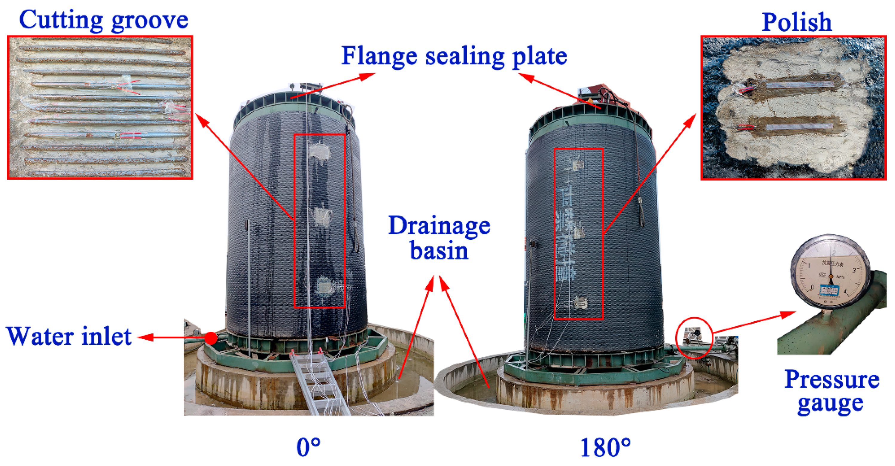
2.3. Monitoring Equipment and Pressurizing Device

2.3.1. Monitoring Equipment

A DH3821 high-speed static data acquisition equipment was used for data monitoring and collection. Inside the steel cylinder, it was inconvenient to arrange the instrument due to internal water pressure loading. The strain gauges used for concrete, prestressed steel wire, and mortar were all resistance-type strain gauges, as shown in Figure 4. Among them, the concrete and mortar strain gages were paper-based strain gauges with a gauge length of 100 mm, and the steel wire strain gauges were rubber-based with a gauge length of 3 mm. The actual resistance values of all strain gages were measured before the test. The resistance values of paper-based strain gages were (119.7 ± 0.1) Ω, and the rubber-based strain gages were (120.4 ± 0.1) Ω. All strain gauges were connected to the data acquisition equipment through wires and signal input lines. The monitoring equipment included 32 channel collectors, which fully met the requirements of the measuring points.

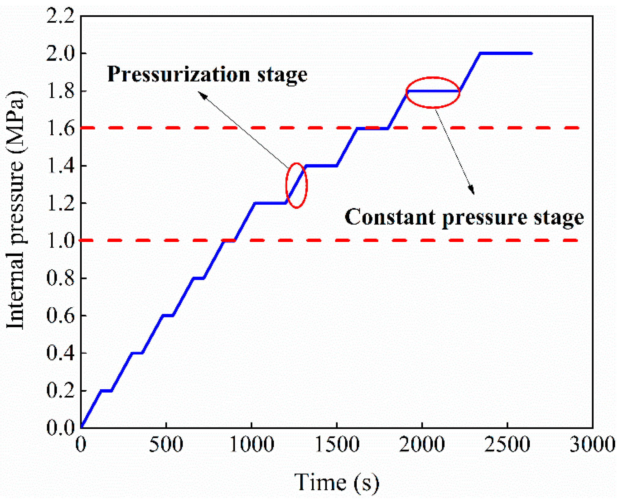
2.3.2. Pressurizing Device

The vertical sleeve-type water testing machine was used as a pressurizing device. PCCP was installed outside the core barrel with sufficient rigidity. There was a 100 mm cavity gap between the internal surface of the test PCCP and the pressurizing core cylinder, as shown in Figure 5. The pressurizing device could be used for PCCP with maximum inner diameter of 4.0 m and maximum length of 6.0 m, which completely satisfied the size requirements of the internal water pressure test of this study.

2.4. Process and Method

The test was conducted in accordance with the code GB/T 15345 [33]. Before pressurization, the equipment needed to be commissioned to determine the normal operation of the detection devices at each monitoring point. The specific arrangement of the test is shown in Figure 6.
Multi-stage loading method was used in this test, and 10 data were collected for each stage of loading. The test requirements of accuracy could be ensured due to the variation of strains ranging below 10 με. Therefore, test data were averaged to obtain the strain of the stage loading. During the test, the pressure increment was set to 0.2 MPa. When the pressure was less than 1.0 MPa, the pressure of each stage was stabilized for 1 min. When the pressure was greater than 1.0 MPa, the pressure of each stage was stabilized for 3 min. When the pressure was over 1.6 MPa, each stage was stabilized for 5 min. At each stage, the strain data were collected when the pressure was stable. The pressurization process is shown in Figure 7. The internal water pressure was uniformly exerted before 1.0 MPa, and the pressurization time increased with the increase in pressure after 1.0 MPa. When the pressure was to be increased to 2.0 MPa, the water pressure could not be stabilized but showed a continuous drop and finally stabilized at 1.9 MPa. Therefore, the final test pressure was 1.9 MPa.

3. Experimental Results

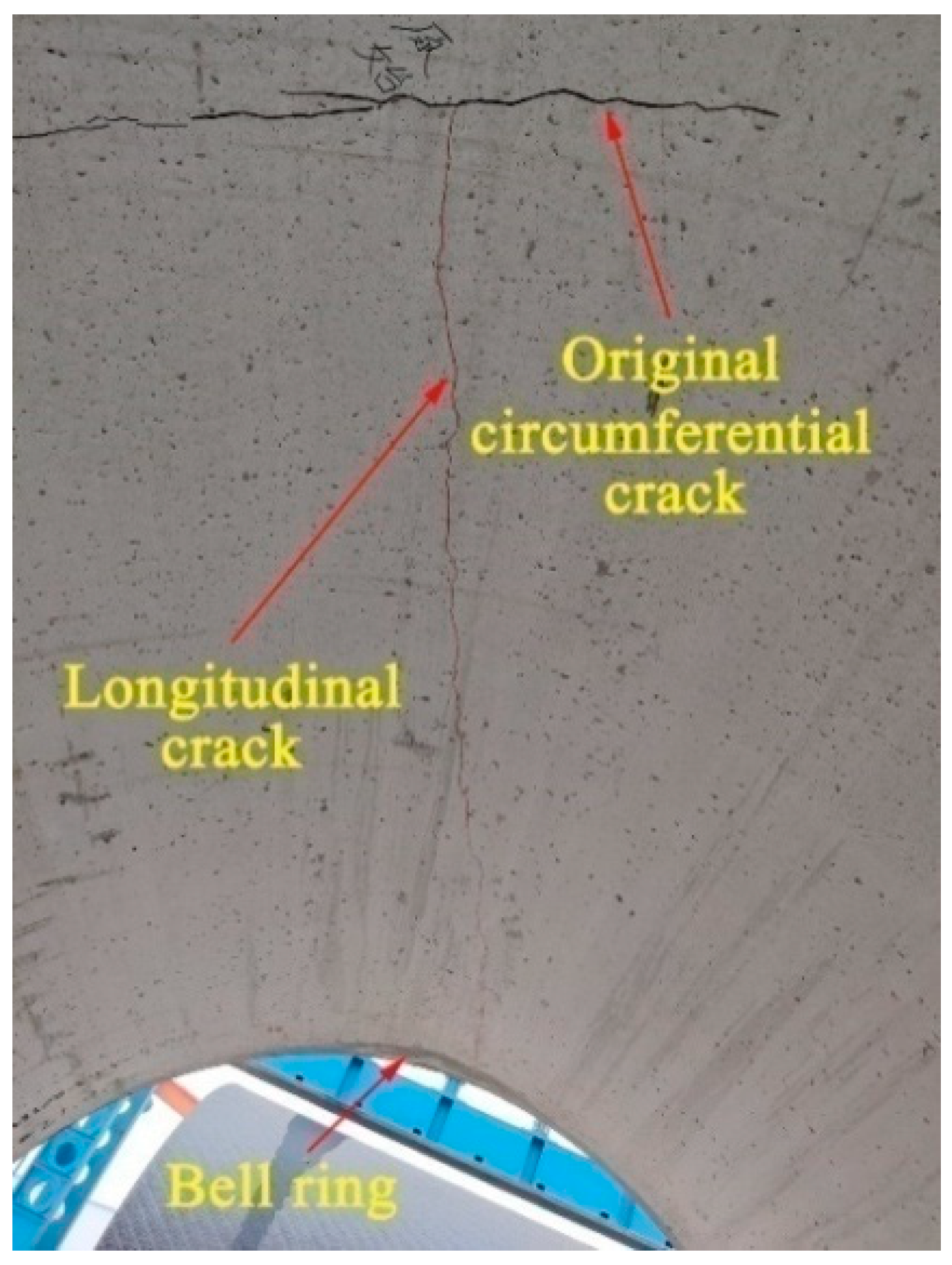
3.1. Failure Progress

When the internal water pressure increased from 1.8 MPa to 2.0 MPa, a slight noise was heard in measuring cross section 1. After the pressurization test, the internal surface of the pipe was checked, and a longitudinal crack about 1.6 m away from the spigot ring was observed, as shown in Figure 8. The crack started from the existing circumferential crack before the test, corresponding to measuring cross section 1, and longitudinally extended to the bell ring. It can be seen from the measurement results that the width gradually decreased with the longitudinal extension. The crack at measuring cross section 1 was the widest, about 0.10 mm. The width corresponding to measuring cross section 2 was about 0.04 mm, and the width was about 0.02 mm for measuring cross section 3. It should be noted that since the crack was measured after the test of pressurization, the actual crack width was greater than the measured value.

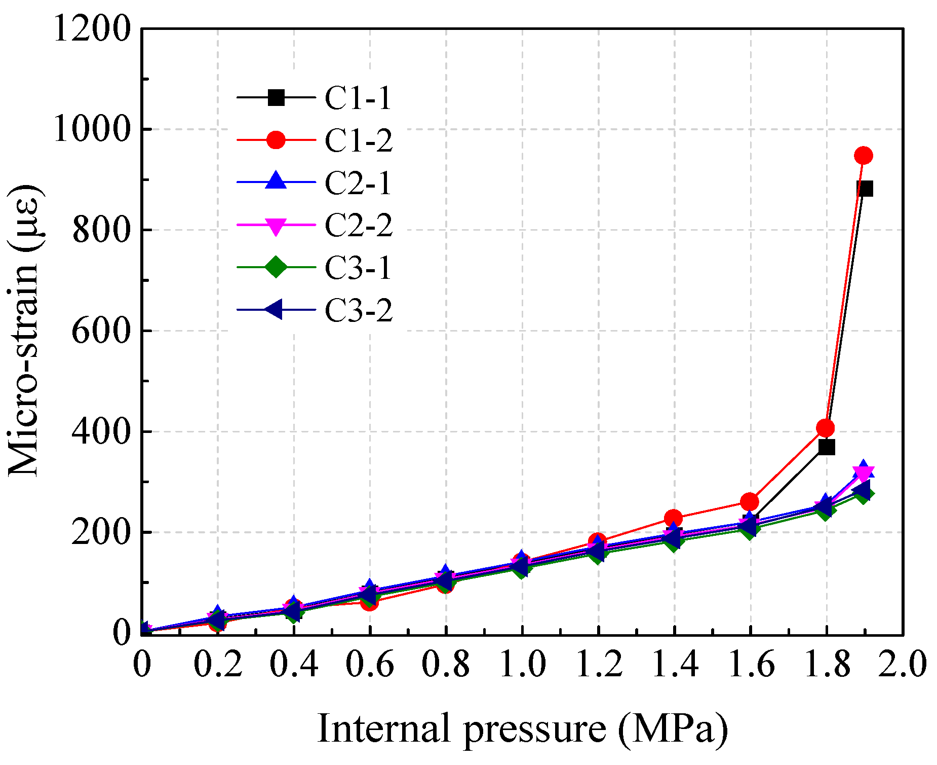
3.2. Strains of Outside Concrete

Test results of the strain on the outer concrete surface of PCCP under internal water pressure are shown in Figure 9. When the pressure was lower than 1.6 MPa, the concrete strain linearly increased with the increase of internal water pressure. When the pressure increased from 1.6 MPa to 1.8 MPa, the slope of concrete strain increased slightly at monitoring zone 1. When the pressure was 1.9 MPa, the concrete strain in the monitoring cross section 1 suddenly increased with the maximum tensile strain of 948 με. The strain growth rate of concrete in monitoring cross sections 2 and 3 increased slightly. This was consistent with the observed crack on the internal surface that longitudinally extended corresponding to the outside monitoring cross sections. The internal surface crack caused the sudden tension of the outer surface concrete. This was a result of internal force balancing in the cracked cross section of test PCCP.

3.3. Strains of Prestressed Steel Wire

Test results of the strain of prestressed steel wire of PCCP under internal water pressure are shown in Figure 10.
It can be seen that the strain growth of the steel wire was similar to that of concrete at the same measuring zone. When the pressure was lower than 1.6 MPa, the strain steadily increased with the increase in internal water pressure. When the water pressure increased from 1.6 MPa to 1.8 MPa, the strain curve slope of the prestressed steel wire trended upward at monitoring cross section 1. When the water pressure reached 1.9 MPa, the strain growth rate of the prestressed steel wire at monitoring cross section 1 increased rapidly, while the strain increased slightly at monitoring cross sections 2 and 3. This was also consistent with the crack at the internal surface of pipe concrete and indicated the joint works of prestressed steel wire and concrete core. With the increase in tension stress at the outer wall concrete, the tensile deformation transferred to the prestressed steel wire [34].

3.4. Strains of Protective Layer Mortar

Test results of the strain of protective mortar of PCCP under internal water pressure are shown in Figure 11. Before the pressure of 1.8 MPa, the strain of the protective mortar increased linearly with the increase in internal water pressure. When the pressure reached 1.9 MPa, the strain of the protective mortar at measuring cross section 1 exceeded 1000 με. When the pressure was between 1.6 MPa and 1.8 MPa, the protective mortar was still in a linear growth stage. This indicated the released process of the tensile stress from inside to outside caused by the cracking of the inside concrete. When the pressure exceeded 1.8 MPa, the mortar strain measuring cross section 1 also increased rapidly, while the strain growth rate of mortar in measuring cross sections 2 and 3 increased slightly.

4. Evaluation of the Limit State on Pipe

4.1. Calculation of Limit State Control Strain

The control strain at the limit state criterion was calculated by the regulations of AWWA C304 [5] and CECS 140 [25]. Due to the existence of prestressing, a certain compression stain (εc0) occurred in the concrete core. When the compressive stress of concrete decreased with increasing internal water pressure, the concrete would come into a tensile condition. Therefore, the real tensile strain of concrete under internal water pressure included the pre-compression strain and the strain detected by the strain gauges. In addition, an increase in prestressing loss made the gross wrapping stress in prestressed steel wire decrease. Therefore, the compressive strain caused by prestress loss should be deducted from the control strain at each stage.
In summary, the actual control strain of concrete (εct) and actual control strain of steel wire (εwt) should be modified according to Equations (1)–(3). In addition, the theoretical cracking control strain of mortar (εmt) is determined by Equation (4) [35].
ε ct = ε ct ε c 0
ε wt = ε wt σ pe E s
σ pe = σ con ( 1 0.08 ϕ t ϕ 0.5 E s E c ρ y ) σ 3
ε mt = 0.5 × 0.7 f cu , k E c + α n m f tk 7713 ( f mc , k ) 0.3
where the εct and εwt are the theoretical calculated strain at different stages of concrete and prestressed steel wire, respectively; σpe is the actual applied prestress, MPa; σcon is the gross wrapping stress, MPa; Es and Ec are the moduli of elasticity of prestressed steel wire and concrete, respectively, MPa; ϕt is the influence coefficient of the production process, which is 1.0 for embedded-cylinder PCCP; ϕ is the reinforcement influence coefficient, which is 1.0 for single-layer steel wire; ρy is the reinforcement ratio of prestressed steel wire, %; σs3 is the prestress loss due to concrete shrinkage and creep [25], MPa; nmt is the ratio of theoretical cracking control strain to the elastic strain of mortar; fcu,k is the standard value of cubic compressive strength of concrete, MPa; Em is the elasticity modulus of mortar, MPa; fmc,k is the standard value of cubic compressive strength of mortar, MPa; α is the control cracking coefficient of mortar; ftk is the standard value of tensile strength, following the code [31]; nm is the ratio of elasticity modulus between mortar and concrete; and εme is the elastic strain of mortar.
The calculation and correction results are listed in Table 3, where “−” represents compression. The crack widths corresponding to microcracking and visible cracking are 0.025 mm and 0.05 mm, respectively.

4.2. Evaluation of the Limit States

(1)
Outside concrete
As shown in Figure 12, the maximum strains of concrete in each measuring cross section were less than 250 με when the internal water pressure was lower than 1.4 MPa. This indicated that the concrete worked at the pre-compression stage. With the increase in internal water pressure, the concrete at monitoring cross section 1 reached the decompression state at 1.4~1.5 MPa and the elastic limit at 1.6~1.7 MPa, while the microcracks occurred at 1.7~1.8 MPa. The concrete measuring at cross sections 2 and 3 was in an elastic state before the pressure of 1.9 MPa. When the pressure increased to 1.9 MPa, the concrete at monitoring cross section 2 reached the elastic limit, and it was still in the elastic stage at monitoring cross section 3. Combined with the crack condition of the inside concrete of the pipe, the analytical results were consistent with the test results.
The decompression point means the pre-compression stress in the concrete core dropped to zero. Two lines (1.5εce and 11εce) are drawn to separately express the microcracking and visible cracking on concrete. Generally, microcracking corresponds to a stage of tensile softening [7]. This indicates that the tensile capacity of concrete decreases gradually until visible cracking appears. The appearance of visible cracks means that the structure exceeds the serviceability limit state. In this test, although the strain of the outside concrete suddenly increased due to the cracking of inside concrete, the maximum strain of outside concrete was still less than 11εce, i.e., the outside concrete of the PCCP was at the serviceability limit state when the water pressure was less than 1.9 MPa.
(2)
Prestressed steel wire
As shown in Figure 13, the strain of prestressed steel wire in monitoring cross section 1 suddenly increased by about 300 με when the water pressure exceeded 1.8 MPa. Combined with the experimental observation, this sudden increase in strain was caused by the cracking of the internal concrete surface. The strain of steel wire in monitoring cross sections 2 and 3 was about 400 με, and there was no sudden increase.
If concrete cracks developed, the pipe shall behave an elastic response to prevent damage or loss of prestressing, which was defined as the elastic limit [7]. This limit state mainly controls the stress of steel wire to not exceed the gross wrapping stress (1099 MPa). Based on the strain of prestressed steel wire collected by this test, the maximum tensile stress of steel wire was 1091 MPa when the pressure increased to 1.9 MPa. The result shows that monitoring cross section 1 can be considered to reach the elastic limit state, while the steel wires in measuring cross sections 2 and 3 did not reach the elastic limit state under 1.9 MPa internal pressure.
(3)
Protective layer mortar
As seen in Figure 14, when the internal water pressure was less than 1.0 MPa, the mortar strain of each zone was lower than 144 με. This indicated that the mortar was in the elastic stage. When the internal water pressure exceeded 1.0 MPa, the mortar at the spring line exceeded the elastic limit on a stage of tensile softening. At the pressure of 1.0~1.8 MPa, the strains of all measuring points were less than 300 με. When the pressure was 1.8~1.9 MPa, the mortar strain exceeded 1100 με due to the cracking of concrete in monitoring cross section 1. This led to a result of cracking on the mortar and the subsequent development of rapid visible cracking. However, the mortar strain at monitoring cross sections 2 and 3 increased slightly, and the strains of these two cross sections were less than 400 με. This showed that the mortar of all monitoring zones was in the serviceability limit state when the internal water pressure was less than 1.8 MPa, and the mortar in monitoring cross sections 2 and 3 were still in the serviceability limit state when the pressure exceeded 1.8 MPa.
However, it must be noted that the tensile strength of mortar was higher than that of concrete, and the strains at cracking and visible cracking in the mortar by code [5,25] were 4 and 8 times the elastic strain, respectively. This may overestimate the tensile strain of mortar. This was verified by a test carried out by Hu [16], where the cracking strain of mortar was 100 με during the test. Although the bearing capacity of mortar was generally ignored during the design of PCCP, the overestimated tensile strain was disadvantageous for durability control of the PCCP operation.
In summary, when the internal water pressure was 0~1.8 MPa, the composite materials of concrete, prestressed steel wire, and protective mortar jointly worked with good mechanical performance. The outside concrete and mortar were under the serviceability limit state. When the internal water pressure exceeded 1.8 MPa, the pipe was damaged due to the cracking of the concrete and the outer mortar. This indicated that the pipe exceeded the serviceability limit state. The maximum tensile stress of steel wire reached the gross wrapping stress. A damaging behavior occurred in the pipe when the internal water pressure exceeded 1.8 MPa. However, the pipe was basically at an elastic limit state when the final internal water pressure was 1.9 MPa during this test.

5. Evaluation of Bearing Capacity of the Pipe

5.1. Calculation of P0, Pt, and Pb

The decompression pressure P0, the mortar visible cracking pressure Pt, and the burst pressure Pb can be calculated by the following equations [5,6,25]:
P 0 = A s σ pe B r 0
P t = A s σ pe + α f tk A n B r 0
P b = A s f su + A y f y B r y
where As and Ay are the area of steel wire and steel cylinder, respectively, mm2/m; σpe is the actual applied prestress, MPa; An is the converted area of the cross section of pipe core concrete, steel cylinder, prestressed steel wire and mortar, mm2/m; B is the calculated length, taken as 1000 mm; α is the control cracking coefficient of mortar; ftk is the standard value of concrete tensile strength, following the code [31]; r0 is the calculated radius of the pipe wall cross section, mm; ry is the outer diameter of the steel cylinder, mm; fsu is the tensile strength of steel wire, MPa; and fy is the design value of tensile strength of steel cylinder, taken as 215 MPa [25].
The calculation results of P0, Pt, and Pb are presented in Table 4. The test values of P0 and Pt increased by 9.4% and 8% compared with the theoretical calculation values. The calculation results were slightly lower than the test values. The PCCP will burst at 2.41 MPa according to the calculation due to the tensile stress exceeding the ultimate tensile strength of the steel wire.

5.2. Bearing Capacity under Internal Water Pressure

The stress state of outside concrete was different from that of inside concrete due to the existence of the steel cylinder. According to the research [18], the test value of P0 at inside concrete was about 20% lower than the calculated value, while the test value of P0 at outside concrete was 9.5% higher than the calculated value. In this experiment, the test value of P0 at outside concrete was 9.4% higher than the calculated value, which was consistent with the reference [18]. It can be conservatively inferred that the test value of P0 at the inside concrete was about 1.0 MPa in this test. Therefore, P0 at the outside concrete was about 1.4 times of the pressure of the inside concrete, which meant that the cracks of the inside concrete appeared earlier than the outside concrete. This was consistent with the analysis results.
Based on the strain measurements obtained in this study and control strain regulated in the codes [5,25], in the protective layer mortar, visible cracks appeared at 1.9 MPa. In addition, the tensile strength of prestressed steel wire and steel cylinder used in Equation (7) was lower than the measured strength values of materials, that is, the actual internal pressure of the pipe burst was higher than the theoretical calculation value. In summary, the concrete cracking pressure and pipe bursting pressure were 1.0 MPa and 2.4 MPa, respectively. The cracking pressures of concrete and the bursting pressures of pipe were 2.5- and 6-times that of the working pressure. This indicated that the PCCP had sufficient safety in actual operation. However, the tensile control strain of mortar may be overestimated by the codes [5,25]. During PCCP design and operation, more attention should be paid to the durability control of the pipe.

5.3. Mechanical Response of PCCP under Internal Water Pressure

Combined with the test and analysis results, the mechanical response of PCCP under internal water pressure can be divided into the following different stages:
(1)
Prestressing stage (0~1.0 MPa)
In this stage, the concrete core and the steel cylinder of PCCP are under the pre-compression condition. Under the action of internal water pressure, no more than 1.0 MPa, all the components of the PCCP are deformation compatibility, as shown in Figure 15.
(2)
Decompression stage (1.0~1.4 MPa)
In this stage, it is conservatively considered that microcracking will occur when the mortar exceeds the ultimate elastic strain based on the result of the limit state evaluation, as shown in Figure 16a. With the increase of internal water pressure, the inner and outer wall concrete reaches the decompression state, respectively. The pre-compression is completely offset by the tensile stress induced by water pressure, and the inside concrete usually reaches the decompression state earlier than the outside concrete, see Figure 16b,c. More cracks appear in the mortar layer.
(3)
Stage of concrete microcracking (1.4~1.7 MPa)
In this stage, the inside and outside concrete reach the elastic limit and then appear microcracking, as shown in Figure 17.
(4)
Visible crack appeared on concrete and mortar (1.7~1.9 MPa)
In this stage, visible cracks appear on the concrete core and the protective mortar, as shown in Figure 18.
(5)
Steel cylinder yield and prestressed steel wire broken (1.9~2.4 MPa)
In this stage, the steel cylinder yields and the tensile stress is mainly supported by prestressed steel wire due to the expansion and penetration of concrete cracks. Prestressed steel wire successively reaches the yield and ultimate limit states. When the maximum elongation of prestressed steel wire is exceeded, the fracture occurs in the weak part, as shown in Figure 19.
(6)
Burst stage (Exceed 2.4 MPa)
In this stage, the steel wire cannot play the role of a hoop pipe barrel due to the increased amount of broken wires of PCCP. The deformation of the steel cylinder increases with the internal pressure, which leads to a local block arch failure of outside concrete under the action of punching [15]. Without the confinement of outside concrete, the steel cylinder is free to elongate with large deformation and finally fractures. This leads to a result of a pipe burst at a certain part, as shown in Figure 20.

6. Conclusions

Combined with a key project of water conveying, a full-scale PCCP with a diameter of 3.2 m was tested under internal water pressure. The strain of concrete, prestressed steel wire, and mortar were detected. The bearing capacities of PCCP at different limit states were evaluated combined with theoretical analysis. The following conclusions are drawn:
(1)
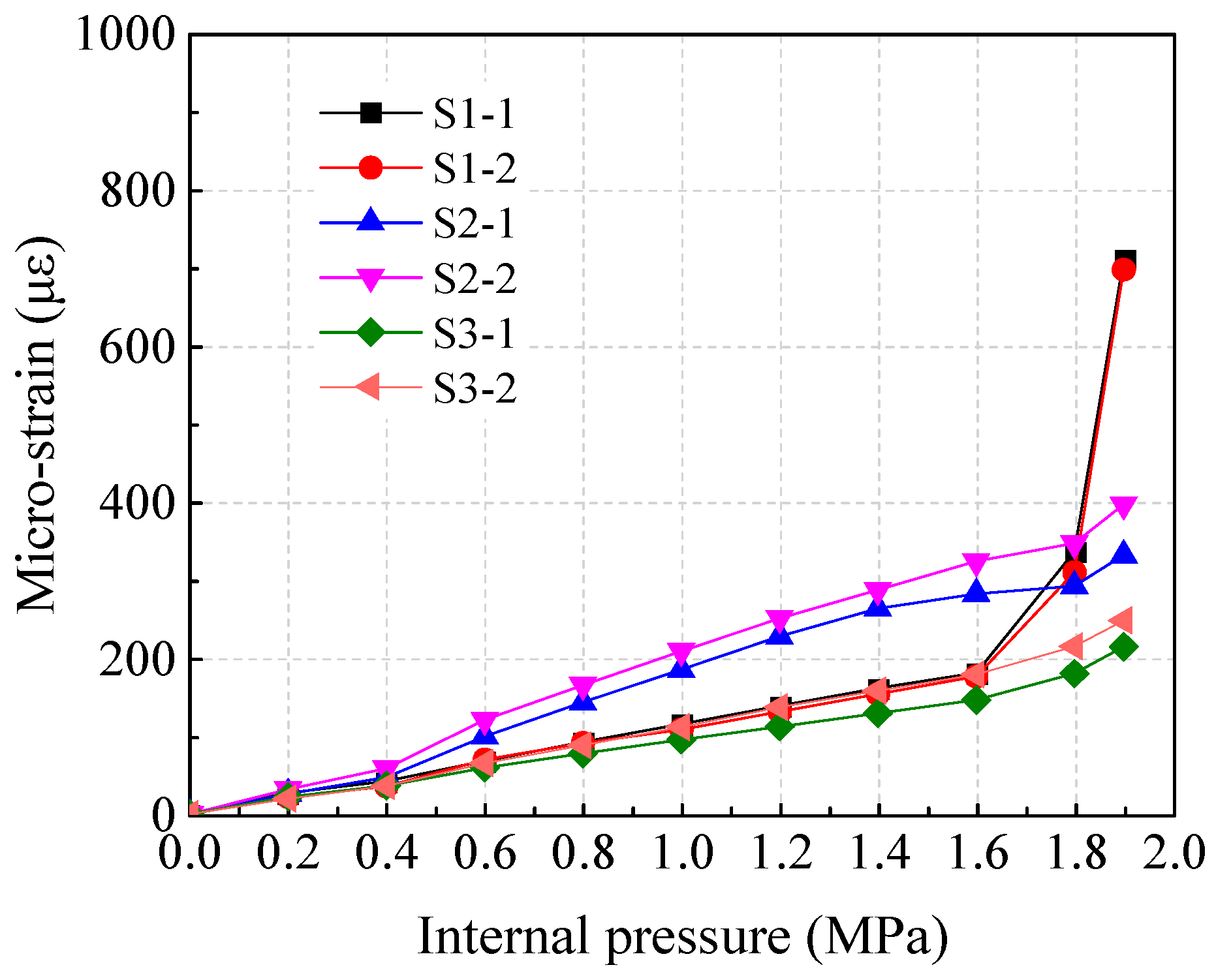
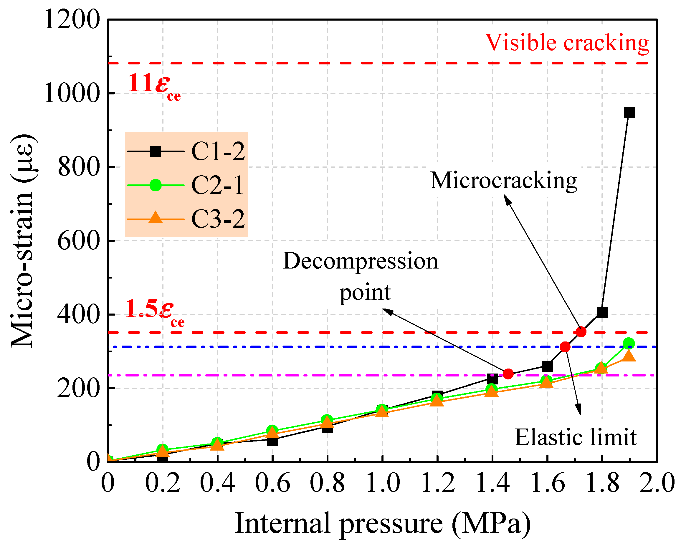
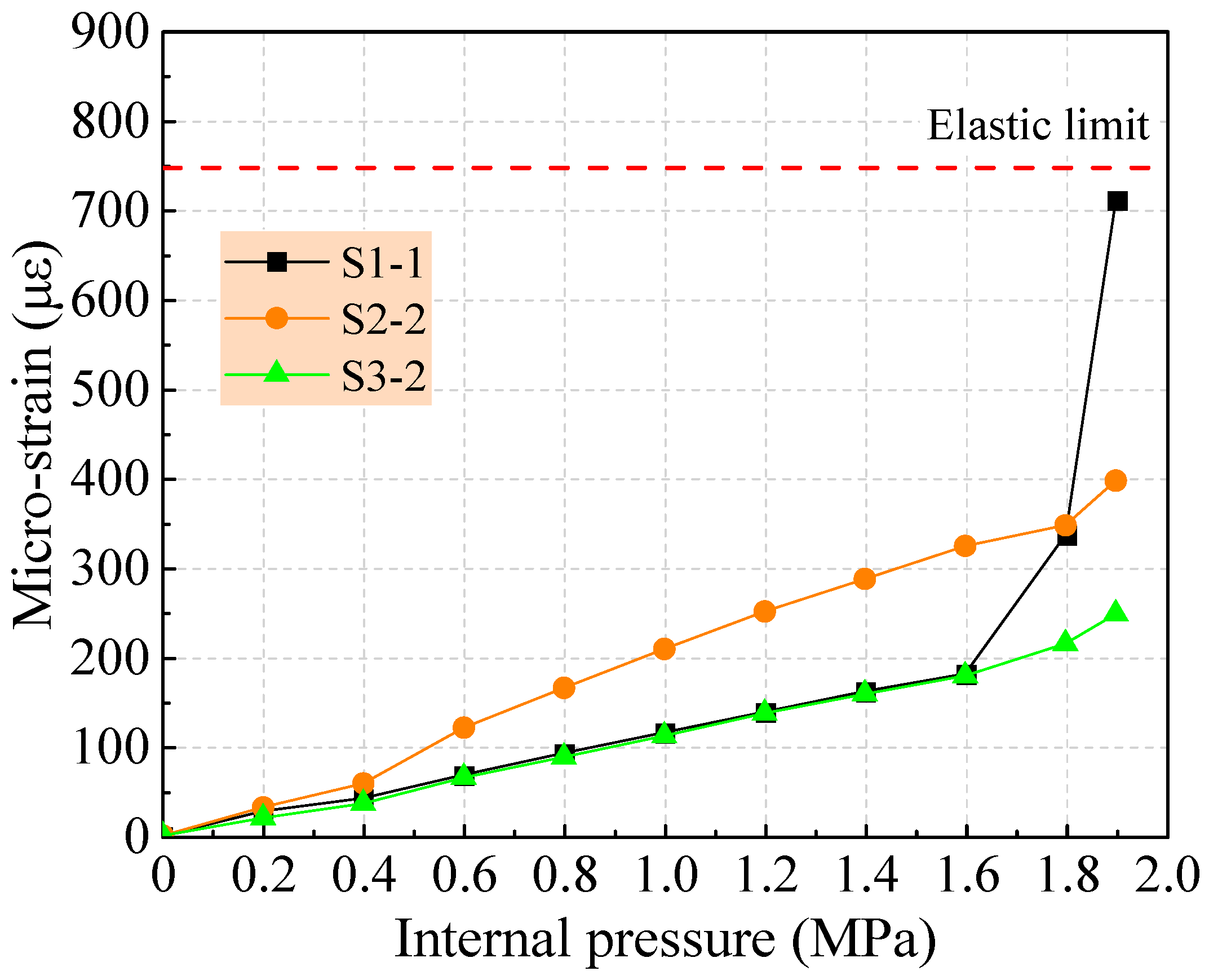
When the pressure was lower than 1.6 MPa, the concrete strain linearly increased with the increase in internal water pressure. When the pressure increased from 1.6 MPa to 1.8 MPa, the concrete strain slope increased slightly at 1 m away from the spigot ring. When the pressure exceeded 1.8 MPa, the strain of the outside concrete at 1 m away from the spigot ring suddenly increased due to the onset of cracking on the corresponding inside concrete, while the concrete at 2.5 m away from the spigot ring only reached the elastic limit, and the concrete was still in the elastic stage at 4 m away from the spigot ring. Differing from the previous results, the concrete crack first appeared on the inside concrete. This may be attributed to the thicker outside concrete.
(2)
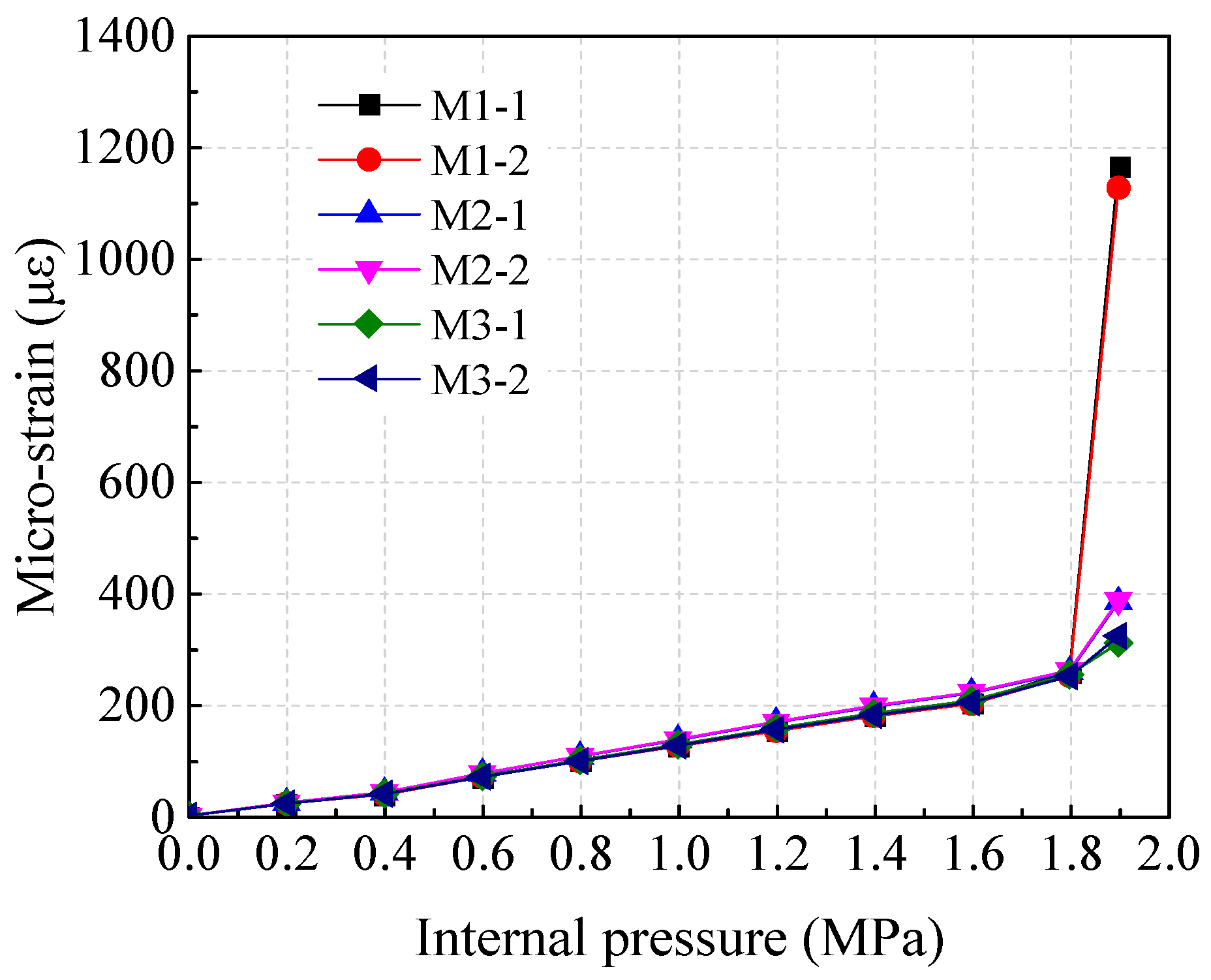
When the internal water pressure is lower than 1.6 MPa, the prestressed steel wire is in the elastic stage. When the water pressure increased from 1.6 MPa to 1.8 MPa, the strain curve slope of the prestressed steel wire trended upward at 1 m away from the spigot ring. Consistent with the outside concrete, the prestressed steel wire at 1 m away from the spigot ring presented a rapid increase in tensile strain when the water pressure exceeded 1.8 MPa, while the strain of prestressed steel wire increased slightly at 2.5 m and 4 m away from the spigot ring.
(3)
The strain of the protective mortar increased linearly with the increased internal water pressure before 1.8 MPa. When the internal pressure exceeded 1.8 MPa, the cracking first appeared in the mortar at 1 m away from the spigot ring and subsequently developed into visible cracking rapidly. However, the mortar strain increased slightly at 2.5 m and 4 m away from the spigot ring.
(4)
When the internal water pressure was 0~1.8 MPa, the composite materials of concrete, prestressed steel wire, and protective mortar jointly worked with good mechanical performance for PCCP under internal water pressure. When the internal water pressure exceeded 1.8 MPa, a damaging behavior occurred in the pipe. The pipe barrel was under the elastic limit state when the final internal water pressure was 1.9 MPa.
(5)
The test values of decompression and cracking pressures increased by 9.4% and 8% compared with the theoretical calculation values. The cracking pressures of concrete and the bursting pressures of pipe were 2.5 and 6 times of the working pressure. This indicated that the PCCP had sufficient safety in actual operation on the premise of ensuring the standardized operation in the working stage. However, the tensile control strain of mortar may be overestimated by the codes. Further research is needed on the mortar strain and strength.

Author Contributions

Conceptualization and methodology, S.Z., H.W. and F.Q.; validation and formal analysis, D.Z. and P.S.; investigation and data curation, D.Z., W.Z. and P.S.; writing—original draft preparation, P.S., D.Z. and W.Z.; writing—review and editing, F.Q and H.W.; supervision, S.Z. and H.W.; funding acquisition, H.W. and S.Z. All authors have read and agreed to the published version of the manuscript.

Funding

This research was funded by the Key R&D projects in Henan Province, grant number 202102310250; the Doctoral Innovation Foundation of North China University of Water Resources and Electric Power, grant number HSZ2021-252; and National Key Engineering Project of Pipe Procurement for Yangtze River to Huaihe River (Henan section), grant number FCGY/JC2020/001.

Data Availability Statement

Data are available with the first author and can be shared with anyone upon reasonable request.

Conflicts of Interest

The authors declare no conflict of interest.

References

  1. Semanuik, S.M.; Mergelas, B. Comparison of identified distress in CCP pipelines operated by water utilities in North America. In Proceedings of the Pipelines 2006: Service to the Owner—Pipeline Division Specialty Conference, ASCE, Chicago, IL, USA, 30 July–2 August 2006; pp. 1–8. [Google Scholar]
  2. Li, C.; Zhong, Z.; Bie, C.; Liu, X. Field performance of large section concrete pipes cracking during jacking in Chongqing—A case study. Tunn. Undergr. Space Technol. 2018, 82, 568–583. [Google Scholar] [CrossRef]
  3. Ge, S.Q.; Sinha, S. Failure analysis, condition assessment technologies, and performance prediction of prestressed-concrete cylinder pipe: State-of-the-art literature review. J. Perform. Constr. Facil. 2012, 28, 618–628. [Google Scholar] [CrossRef]
  4. Li, Z.; Liu, Y.Z.; Yan, X.; Ren, G.P.; Wang, Y.Q. Summarization and application of high-tech into wanjiazhai projects. Eng. Mech. 2007, S2, 21–32. [Google Scholar]
  5. ANSI/AWWA C304–2014; AWWA Standard for Design of Prestressed Concrete Pressure Pipe. American National Standards Institute, American Water Works Association: Denver, CO, USA, 2014.
  6. GB/T 19685-2017; Prestressed Concrete Cylinder Pipe. China Standards Press: Beijing, China, 2017.
  7. ANSI/AWWA C301–2014; AWWA Standard for Prestressed Concrete Pressure Pipe, Steel-Cylinder Type. American National Standards Institute, American Water Works Association: Denver, CO, USA, 2014.
  8. Hu, H. Analysis of Experiment and Simulation for CFRP Renewal of Prestressed Concrete Cylinder Pipe with Internal Pressure. Master’s Thesis, China Institute of Water Resources and Hydropower Research, Beijing, China, 2017. [Google Scholar]
  9. Higgins, M.S.; Paulson, P.O. Fiber Optic Sensors for Acoustic Monitoring of PCCP. In Proceedings of the Pipelines 2006: Service to the Owner—Pipeline Division Specialty Conference, ASCE, Chicago, IL, USA, 30 July–2 August 2006; pp. 1–8. [Google Scholar]
  10. Zarghamee, M.S.; Eggers, D.W.; Ojdrovic, R.; Rose, B. Risk analysis of prestressed concrete cylinder pipe with broken wires. In Proceedings of the Pipelines 2003: New Pipeline Technologies, Security, and Safety—Pipeline Engineering & Construction International Conference, ASCE, Baltimore, MD, USA, 13–16 July 2003; pp. 599–609. [Google Scholar]
  11. Omar, E.; Khaled, E.S.; Gilles, H.; Thomas, L.D. Risk Management System for Prestressed Concrete Cylinder Pipeline: Practical results and experience on the Great Man Made River. In Proceedings of the Pipelines 2005: Optimizing Pipeline Design, Operations, and Maintenance in Today’s Economy—Pipeline Division Specialty Conference, ASCE, Houston, TX, USA, 21–24 August 2005; pp. 241–251. [Google Scholar]
  12. Zarghamee, M.S.; Heger, F.J.; Dana, W.R. Experimental evaluation of design methods for prestressed concrete pipe. J. Transp. Eng. 1988, 114, 635–655. [Google Scholar] [CrossRef]
  13. Heger, F.J.; Zarghamee, M.S.; Dana, W.R. Limit-states design of prestressed concrete pipe. I: Criteria. J. Struct. Eng. 1990, 116, 2083–2104. [Google Scholar] [CrossRef]
  14. Zarghamee, M.S.; Fok, K.L.; Sikiotis, E.S. Limit-states design of prestressed concrete pipe. II: Procedure. J. Struct. Eng. 1990, 116, 2105–2126. [Google Scholar] [CrossRef]
  15. Zarghamee, M.S. Hydrostatic pressure testing of prestressed concrete cylinder pipe with broken wires. In Proceedings of the Pipelines 2003: New Pipeline Technologies, Security, and Safety—Pipeline Division Specialty Conference, ASCE, Baltimore, MD, USA, 13–16 July 2003; pp. 294–303. [Google Scholar]
  16. Hu, S.W.; Shen, J.; Liu, X.X.; Wang, D.L. Study on bearing capacity test of internal water pressure of super-caliber PCCP. Adv. Sci. Technol. Water. Res. 2009, 29, 9–12. [Google Scholar]
  17. Dou, T.S.; Cheng, B.Q.; Hu, H.; Xia, S.F.; Yang, J.X.; Zhang, Q. The prototype test study of prestressed concrete cylinder pipe structure deformation law I: The internal pressure. J. Hydraul. Eng. 2017, 48, 1438–1446. [Google Scholar]
  18. Cheng, B.Q.; Dou, T.S.; Xia, S.F.; Zhao, L.J.; Yang, J.X.; Zhang, Q. Mechanical properties and loading response of prestressed concrete cylinder pipes under internal water pressure. Eng. Struct. 2020, 216, 110674. [Google Scholar] [CrossRef]
  19. Zarghamee, M.S.; Ojdrovic, R.P. Risk Assessment and Repair Priority of PCCP with Broken Wires. In Proceedings of the Pipelines 2001: Advances in Pipelines Engineering and Construction—Pipeline Division Specialty Conference, ASCE, San Diego, CA, USA, 15–18 July 2001; pp. 1–8. [Google Scholar]
  20. Zarghamee, M.S.; Eggers, D.W.; Ojdrovic, R.P. Finite-element modeling of failure of PCCP with broken wires subjected to combined loads. In Proceedings of the Pipelines 2002: Beneath Our Feet: Challengers and Solutions—Proceedings of the Pipeline Division Specialty Conference, ASCE, Cleveland, OH, USA, 4–7 August 2002; pp. 1–17. [Google Scholar]
  21. Ge, S.Q.; Sinha, S. Evaluation of Condition of prestressed concrete cylinder pipe (PCCP) using numerical simulation. Proc. Water Environ. Fed. 2011, 12, 3952–3970. [Google Scholar] [CrossRef]
  22. Hu, B.Y.; Fang, H.Y.; Wang, F.M.; Zhai, K.J. Full-scale test and numerical simulation study on load-carrying capacity of prestressed concrete cylinder pipe (PCCP) with broken wires under internal water pressure. Eng. Fail. Anal. 2019, 104, 513–530. [Google Scholar] [CrossRef]
  23. Romer, A.E.; Bell, G.E.C.; Ellison, R.D. Failure of Prestressed Concrete Cylinder Pipe. In Proceedings of the Pipelines 2007: Advances and Experiences with Trenchless Pipeline Projects—International Conference on Pipeline Engineering and Construction, ASCE, Boston, MA, USA, 8–11 July 2007; pp. 1–17. [Google Scholar]
  24. Shang, P.; Wang, H.; Zhang, D.; Zheng, W.; Qu, F.; Zhao, S. Experimental study on external loading performance of large diameter prestressed concrete cylinder pipe. Buildings 2022, 12, 1740. [Google Scholar] [CrossRef]
  25. CECS 140-2011; Specification for Structural Design of Buried Prestressed Concrete Pipeline and Prestressed Concrete Cylinder Pipeline of Water Supply and Sewerage Engineering. China Planning Press: Beijing, China, 2011.
  26. GB 50332-2002; Structural Design Code for Pipelines of Water Supply and Waste Water Engineering. China Architecture Press: Beijing, China, 2002.
  27. SL/T 352-2020; Test Code for Hydraulic Concrete. China Water Resources and Hydropower Press: Beijing, China, 2020.
  28. GB/T 5223-2014; Steel Wire for Prestressing of Concrete. China Standards Press: Beijing, China, 2014.
  29. ASTM A648-2018; Standard Specification for Steel Wire, Hard-Drawn for Prestressed Concrete Pipe. American Society of Testing Materials: West Conshohocken, PA, USA, 2018.
  30. GB/T 228.1-2010; Metallic Materials—Tensile Testing—Part 1: Method of Test at Room Temperature. China Standards Press: Beijing, China, 2010.
  31. GB 50010-2010(version 2015); Code for design of concrete structures. China Architecture Press: Beijing, China, 2015.
  32. GB 50017-2017; Standard for Design of Steel Structures. China Architecture Press: Beijing, China, 2017.
  33. GB/T 15345-2017; Test Methods of Concrete Pipes for Water Transmission. China Standards Press: Beijing, China, 2017.
  34. Kennison, H.F. Design of prestressed concrete cylinder pipe. J. Am. Water. Works. Ass. 1950, 42, 1049–1064. [Google Scholar] [CrossRef]
  35. Que, X.P. Understandings of Internal and External Pressure Test Load Formulas of PCCP of GB/T 19685—2005 prestressed concrete steel cylinder pipe. China. Concr. Cem. Prod. 2014, 2, 23–26. [Google Scholar]
Figure 1. Cross section composition of PCCP: (a) embedded steel cylinder; and (b) lined steel cylinder.
Buildings 12 01791 g001
Figure 2. Specimens for the compressive strength of concrete.
Buildings 12 01791 g002
Figure 3. Monitoring arrangement (unit: mm): (a) zones for concrete and steel wire; (b) zones for mortar; (c) locations at cross section.
Buildings 12 01791 g003
Figure 4. Type of strain gauge for test: (a) concrete and prestressed steel wire; (b) mortar.
Buildings 12 01791 g004
Figure 5. Vertical internal water pressure device: (a) pressurizing device; (b) cross sectional view of the position of pressurizing device.
Buildings 12 01791 g005
Figure 6. Internal water pressure test.
Buildings 12 01791 g006
Figure 7. Pressurization process.
Buildings 12 01791 g007
Figure 8. Longitudinal crack appeared on the internal surface of the test PCCP.
Buildings 12 01791 g008
Figure 9. Changes of outside concrete strain with internal water pressure.
Buildings 12 01791 g009
Figure 10. Changes of prestressed steel wire strain with internal water pressure.
Buildings 12 01791 g010
Figure 11. Changes of mortar strain with internal water pressure.
Buildings 12 01791 g011
Figure 12. Control strain of outside concrete at each stage.
Buildings 12 01791 g012
Figure 13. Control strain of prestressed steel wire at each stage.
Buildings 12 01791 g013
Figure 14. Control strain of mortar at each stage.
Buildings 12 01791 g014
Figure 15. Prestressing stage.
Buildings 12 01791 g015
Figure 16. Decompression stage.
Buildings 12 01791 g016
Figure 17. Concrete microcracking stage.
Buildings 12 01791 g017
Figure 18. Visible cracking stage.
Buildings 12 01791 g018
Figure 19. Wire broken stage.
Buildings 12 01791 g019
Figure 20. Pipe barrel burst stage.
Buildings 12 01791 g020
Table 1. Geometry and design parameters for test PCCP.
Strength Grade of ConcreteStrength Grade of MortarStrength Grade of Wire (MPa)Thickness of Concrete Core
(mm)
Thickness of Mortar
(mm)
Thickness of Steel Cylinder
(mm)
Wire
Diameter
(mm)
Gross Wrapping Stress
(MPa)
Wire Area
(mm2/m)
C55M451570245251.5710992350
Table 2. Material properties of test PCCP.
MaterialCompressive Strength (MPa)Modulus of
Elasticity
(MPa)
Tensile Strength
(MPa)
Yield Strength
(MPa)
Concrete61 *35,5002.74/
Mortar4524,1653.49/
Sheet steel/206,000470 *300 *
Prestressed steel wire/205,0001620 *1177.5
Note: * Test value, others are determined as per Chinese codes [25,28,31,32].
Table 3. Calculation and modification results of the control strain.
Limit StateStrain
Parameter
MaterialMeaningControl
Criteria
Strain (με)Modified
Strain (με)
Serviceabilityεc0ConcretePre-compression strain of concrete/−235/
εceElastic-strain of concrete/77312
εctmMicrocracking on concrete1.5εce116351
εctvVisible cracking on concrete11εce8471082
εmeMortarElastic-strain of mortar/144/
εmtTheoretically cracking strain of mortar4εme576/
εmtmMicrocracking on mortar6.4εme922/
εmtvVisible cracking on mortar8εme1152/
ElasticεwtWireWire strain corresponding to gross wrapping stressσwtσcon5361748
StrengthεwyWireWire strain corresponding to yield stressσwtfsy57441132
Table 4. Calculation results of P0, Pt, and Pb.
ParameterP0 (MPa)Pt (MPa)Pb (MPa)
Calculated value1.281.762.41
Test value1.401.90/
Publisher’s Note: MDPI stays neutral with regard to jurisdictional claims in published maps and institutional affiliations.

