Article

The Effect of GFRP Wrapping on Lateral Performance of Double Shear Lap Joints in Cross-Laminated Timber as a Part of Timber Bridges

by
Akbar Rostampour Haftkhani
1,*,
Maria Rashidi
2,*,
Farshid Abdoli
3,* and
Masood Gerami
4
1
Wood Science and Technology, Department of Natural Resources, Faculty of Agriculture and Natural Resources, University of Mohaghegh Ardabili, Ardabil 56199-11367, Iran
2
Centre for Infrastructure Engineering, Western Sydney University, Sydney 2000, Australia
3
Department of Wood and Paper Science, Faculty of Natural Resources, University of Tarbiat Modares, Tehran 14117-13116, Iran
4
Department of Wood and Paper Science, Faculty of Natural Resources, University of Tehran, Karaj 14179-35840, Iran
*
Authors to whom correspondence should be addressed.
Buildings 2022, 12(10), 1678; https://doi.org/10.3390/buildings12101678
Submission received: 29 August 2022 / Revised: 19 September 2022 / Accepted: 8 October 2022 / Published: 12 October 2022
(This article belongs to the Special Issue Adoption of Engineered Wood Products in Building Applications)

Abstract

:
Timber elements, such as timber bridges, are exposed to heavy loads. Therefore, reinforcement might be useful. Due to a lack of wood supplies, poplar, a fast-growing tree, could be used to construct CLT (cross-laminated timber). The low density of fast-growing wood species directly impacts the mechanical properties of CLT. Therefore, in this study, a CLT panel was reinforced with GFRP (glass-fiber-reinforced polymer), and the lateral resistance of double shear lap joints in reinforced CLTs with 0-90-0° arrangements in two strength directions was investigated. Lag screws (Ø = 8 mm) at the end distances of 1 and 3 cm were employed for making the lateral test specimens. First, the effect of the number of GFRP layers on lateral resistance of the joints was investigated. The results revealed that, as the number of GFRP layers changed from one to three, the lateral resistance increased by 45.47%, and then, by four layers, it decreased by 1.3%. Since the joints with three layers of FRP had the highest strength, the effects of the end distance and the CLT panel strength directions on the lateral performance of the reinforced and non-reinforced specimens were investigated. The results indicated that the lateral resistance of reinforced CLTs with GFRP was about 26.5% more than the unreinforced ones. Moreover, CLTs in the major strength direction showed 4.2% more lateral resistance than those in the minor strength direction. Moreover, lag screws at the end distance of 3 cm had 60% more lateral resistance than those at the end distance of 1 cm. In terms of failure modes, bearing, shear, and net-tension modes were observed in the CLTs, while Is, IIIs, and IV modes were observed in the lag screws.

1. Introduction

Bridges provide great value to the economy as they form parts of trade routes and links between communities; their assessed cost undervalues their net worth [1]. One of the popular materials for making bridges is timber. Timber bridges, in some situations, are unable to service their community as they are no longer able to handle modern or increased traffic load or conditions and their cost of maintenance [2]. However, it is neither possible nor practical, economically or physically, to replace all timber bridges simultaneously. Thus, they must be maintained or reinforced [3]. Engineered wood products (EWPs), such as cross-laminated timber (CLT) and glued laminated timber (glulam), are useful materials for manufacturing timber bridges. Generally, CLT might be used as decking, and glulam might be used for other parts of timber bridges.
Timber bridges must resist heavy loads for a long time [1]. Joints, as the weakest part of any building due to the damage caused by external loads, might need an increase in load-carrying capacity. For ensuring integrity in timber buildings, the timber elements, such as CLT parts, connect by metal joints, such as angle brackets, T-shape, and hold-downs, etc. External loads should be adopted and transferred to the foundation, while interior loads should be conveyed as shear load, moment, etc. As a result, the structure is subjected to loads and deformations that must not go beyond the design strength and deformation limitations [4]. However, sometimes, loads (hurricanes, earthquakes, etc.) might exceed the design strength. For instance, according to Canbek et al. [5], common roof-to-wall connections of structures were exposed to combined withdrawal and lateral forces during high winds. The lateral force parts were attributable to in-plane and out-of-plane shear loads on the walls. Significant hurricane-induced damage was detected in structures due to the failure of roof-to-wall joints and following water infiltration. As a result, it is important to reinforce the timber, especially in the weak connection spots, to achieve durability [6]. There are several methods, such as applying metals, fiber-reinforced polymers (FRPs), etc., for retrofitting and reinforcing the timber structures. This material can be used as plates, bars, and rods in timber elements. According to Saribiyik and Akguuml [7], strengthening the connections aims to reduce stress concentration, save fiber continuity, and decrease the disadvantages of connection elements, such as nails and bolts. Several studies have been conducted on concrete [8], metal plates [9,10,11,12], rods, and bars as reinforcement in timber-based products.
However, reinforcement with metals might cause some problems in the workability of the products. More specifically, it causes limitations for sawing and cutting the products. Moreover, it should also be noted that steel and metal repairs reduce the structure’s durability in the event of a fire and contribute to the issue of corrosion [13]. To overcome these problems, fiber-reinforced polymers (FRPs) are suggested for timber-based products.
Fiber-reinforced polymers (FRPs) are a family of appealing materials that may provide numerous advantages to wood as a reinforcement for strengthening purposes [14]. When compared to other building materials, FRPs have an exceptional strength-to-weight ratio. The use of FRPs to reinforce structural components in civil infrastructure is successful and has been documented [15,16]. These materials also portray good durability and fatigue characteristics compared to traditional building materials [17]. As a consequence of their utilization, maintenance expenses are lowered. Since steel is susceptible to corrosion when in interaction with the moisture content of the wood, FRPs are a better choice for reinforcing it than steel [7]. FRPs may also be pultruded into a variety of shapes. Glass-fiber-reinforced polymers (GFRPs) appear to be an ideal fiber type for strengthening wood components owing to their cheap cost and high mechanical qualities [7]. Pultruded GFRP rods are more compatible with resin and wood, have stronger resilience to humid or acid conditions, and have superior performance owing to increased bonding and lower weight [18].
Carbon-fiber-reinforced polymer (CFRP) layers improved the moment capacity of unreinforced bolted glulam beam-to-column joints made of spruce–pine–fir up to 59%, which was near to the reinforcing ratio (65%) attained by applying locally cross-laminated glulam elements [19]. Canbek et al. [5] demonstrated that the FRP tie system for roof-to-wall double shear lap joint offered an easy-to-apply, nonintrusive, and practical alternative to traditional joints in spruce–pine–fir wood under the uplift and lateral loadings. GFRP layers are applied to strengthen split wood stringers made from Douglas fir for shear and bending loads. Depending on the extent of beam fracture before reinforcing, the suggested reinforcement design enhances stiffness by 5.5–52.8% [20]. In shear-strengthening wood stringers with horizontal cracks at their ends, Hay et al. [21] demonstrated that diagonal GFRP layers were more successful than vertical ones in reinforcing creosote-treated Douglas fir beams. The mechanical properties of connecting points of fiber-reinforced longitudinal notched lap joints made of black pine lumber were examined [7]. The findings showed that GFRP could be used as a reinforcing method in connecting the timber members. For thin topping wood-concrete composite connections, Skinner et al. [22] proved that GFRP plate connectors might be a viable option for self-tapping screws. Wu et al. [23] developed a GFRP wood fastened connection as an alternative to the potentially corrosive nature of pine wood joints made with steel plates. According to their results, the majority of GFRP wood bolted connections failed due to the bearing failure of the bolt holes in the wood panels under lateral stress. Lower ultimate strength and ductility were observed in CFRP plate shear connections [24].
Regarding the lateral performance of CLTs, several investigations have been carried out. Joyce [25] demonstrated that fasteners must penetrate sufficiently into CLT at least one layer that cross-reinforces a face lamella to activate toughening against lateral load splitting. Ringhofer et al. [26] indicated that fasteners placed through the CLT side face and forced laterally showed ductile behavior, allowing good load-sharing within groups of fasteners. In terms of failure mechanisms, for lateral-force-resisting mechanisms of CLT buildings made of spruce–pine–fir, a connection component with a double inclination of fasteners (self-tapping screws) showed satisfactory performance [27]. The lateral force resistance of CLT elements was improved with diagonal struts fastened with nails [28].
The end distance of fasteners is an important feature of connections to consider. Fasteners in a wood connection must be positioned at a certain distance from the joint member’s end. Several studies on the shear performance of CLT joints have been conducted; however, no studies have assessed the lateral resistance of fasteners with varying end distances in double shear plane lap joints. If screws are put too near to the end of the CLT pieces, the wood may split before the connections give, causing the connection to fail [29]. Increased dowel row spacing and self-tapping screw end distance improve CLT joint ductility and displacement capability under monotonic and cyclic loading [30]. The arrangement of the fasteners meaningfully affects the joint’s yield mode and capacity for tolerating loads in timber-to-timber connections. Moreover, the initial stiffness and ductility coefficient decreased with increasing the end distance of the fasteners. The initial stiffness of the connections improved as the fastener spacing increased [31]. Due to the wooden nails’ improved tensile capability, specimens with inclined nails subjected to combined shear and tensile stresses had better shear resistance [32]. With decreasing dowel diameters, especially in low-density wood, the number of dowels in all kinds of timber connectors is significantly affected by the applied tensile force [33].
So far, no study of the lateral resistance of lag screws in CLTs with double shear lap joints in CLTs built of poplar wood and strengthened with GFRP has been conducted. It has been shown that bolting the laminates together may increase the strength of CLT short columns by roughly 20% [34].
Nowadays, there is a shortage of wooden and timber supplies worldwide. Thus, fast-growth species, such as poplar, could be a reliable alternative.
According to the CLT handbook [35], fasteners may be used to connect CLT walls in the transverse direction with concealed metal plates, such as double shear lap joints. The thickness of the metal plate may vary in this kind of junction depending on the forces. Although these connections provide benefits for overexposed plates and brackets, particularly in fire performance, they need to be precisely profiled using CNC technology at the factory. As a result, this research aimed to conduct experimental testing to explore the effects of employing GFRPs in lag screwed double shear plane lap joints with end distances of 1 and 3 cm in the major and minor axes CLT as part of timber bridges manufactured from poplar wood (Populus alba).

2. Materials and Methods

2.1. Wood

The logs were obtained from (Populus alba) trees and were cut into planks measuring 200 × 11 × 2.5 cm (length, width, thickness). In Ardabil City, Iran, the average temperature ranged from 22 to 30 degrees Celsius, and the average relative humidity ranged from 60 to 70 percent from June to September. The spring and summer months were used to air-dry the boards until they attained a consistent weight and had an average moisture content of around 12%. The weight of various control samples was regularly monitored, and the moisture content of the wood was assessed and managed to regulate the boards’ humidity. Drying was carried out until the samples had a weight that was practically constant for up to two weeks. Then, CLT was created using the dried boards.

2.2. Manufacture of CLT

After sawing, air-dried planks with an oven-dry density of 0.381 gr/cm3 and modulus of elasticity (MOE), modulus of rupture (MOR), and shear strength parallel to the grains of 7380 MPa, 59 Mpa, and 4.96 Mpa were planned S4S up to the dimensions of 90 × 19 mm (width and thickness) for all tests. Planks without defects or cracks were selected for manufacturing 3-ply CLT panels. One-component water-resistant polyurethane glue was used to bond the surfaces and edges of layers and GFRP layers with a spread rate of 300 g/m2. For fabricating 3-layer CLT panels, the layers were matched and pressed for 150 min at a pressure of 1 Mpa. In accordance with the producer’s instructions, the glue assembly, curing, and opening times were, respectively, 20, 90, and 150 min. Bidirectional woven GFRP glued to the CLT specimens is as shown in Figure 1.
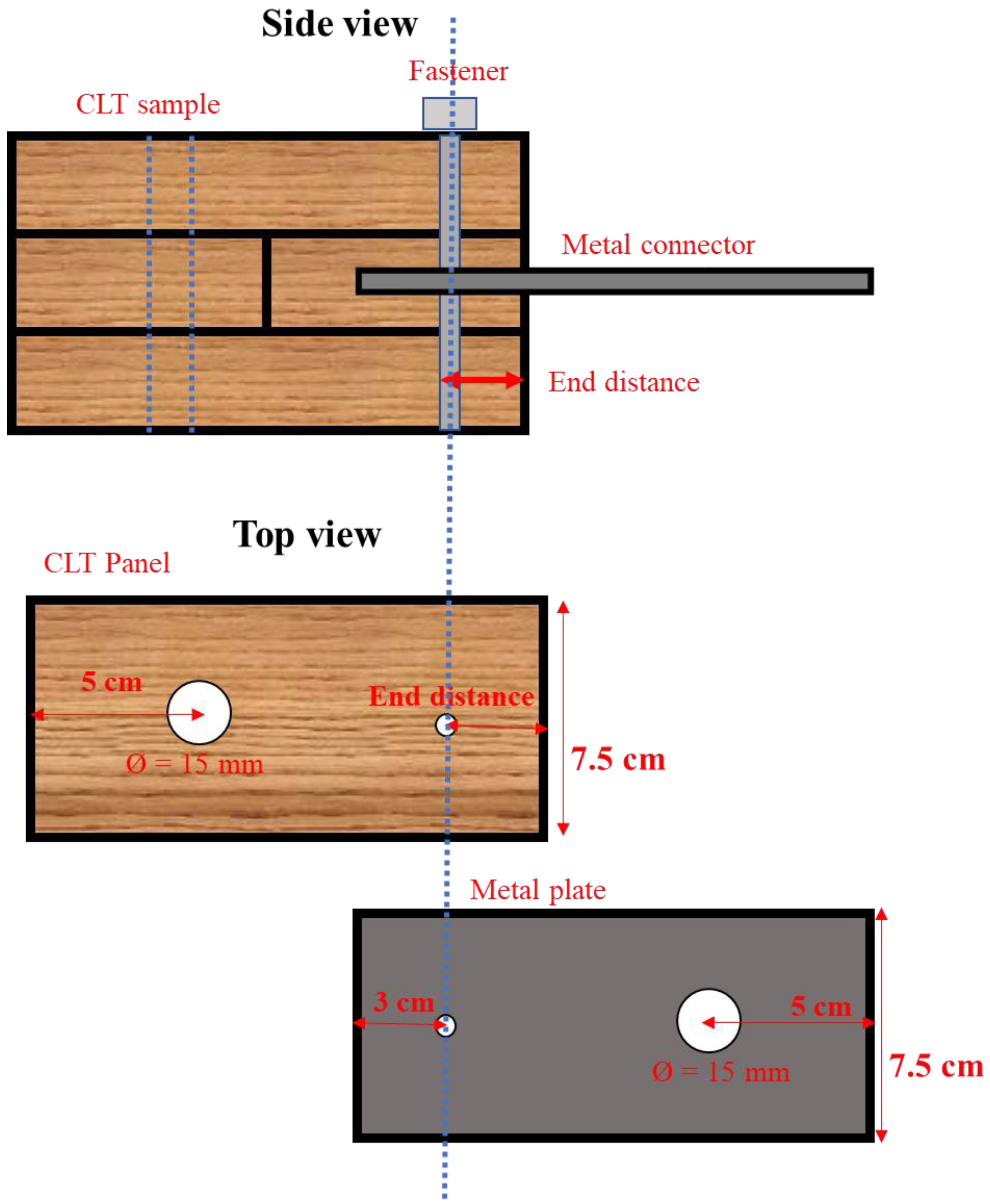
The manufactured CLT sheets were cut into specimens with dimensions of 150 × 75 mm (length, width) to prepare lateral test specimens. The thickness of the CLT panel was 57 mm plus the thickness of the fibers’ GFRP layers. Structural steel A36 sheets with dimensions of 150, 75, and 4 mm (length, width, and thickness) were also used to construct the joints, as shown in Figure 2. A kerf with dimensions of 6 and 62 mm in thickness and depth was made into the middle of the CLT thickness to insert the steel sheet.
In the first step, the effects of the number of GFRP layers on the lateral resistance of the CLT joint were investigated (Table 1). Therefore, CLT panels with 1, 2, 3, and 4 layers of GFRP (for each surface), as shown in Figure 1, were manufactured and tested under lateral loading and compared with unreinforced samples. By adding GFRP to the CLT samples, about one millimeter was added to the thickness of the samples for each layer of reinforcement on all surfaces. Therefore, the thickness of the control sample was 57 mm, and the specimens reinforced with one, two, three, and four layers of GFRP were 58, 59, 60, and 61 mm, respectively. The end distance was selected as 1 cm. Subsequently, the specimens with the highest resistance were selected for the next tests. In the next step (Table 2), the effects of the end distance (1 and 3 cm) and the panel strength directions on the lateral resistance of the reinforced specimens with the highest resistance and the non-reinforced specimens were investigated. The end distances were considered from the center of the hole. The characteristics of the GFRP are given in Table 3. Lag screws with a diameter of 8 mm as a fastener were used in this research, as exhibited in Table 4. A predrilled hole with a diameter of 5 mm was created through the CLT thickness for inserting the screws. The screw was inserted with end distances of 1 and 3 cm.
All the CLT samples of the joints were subjected to equilibrium conditions at relative humidity and temperature of approximately 65 °C and 20 °C, respectively.

2.3. Lateral Test

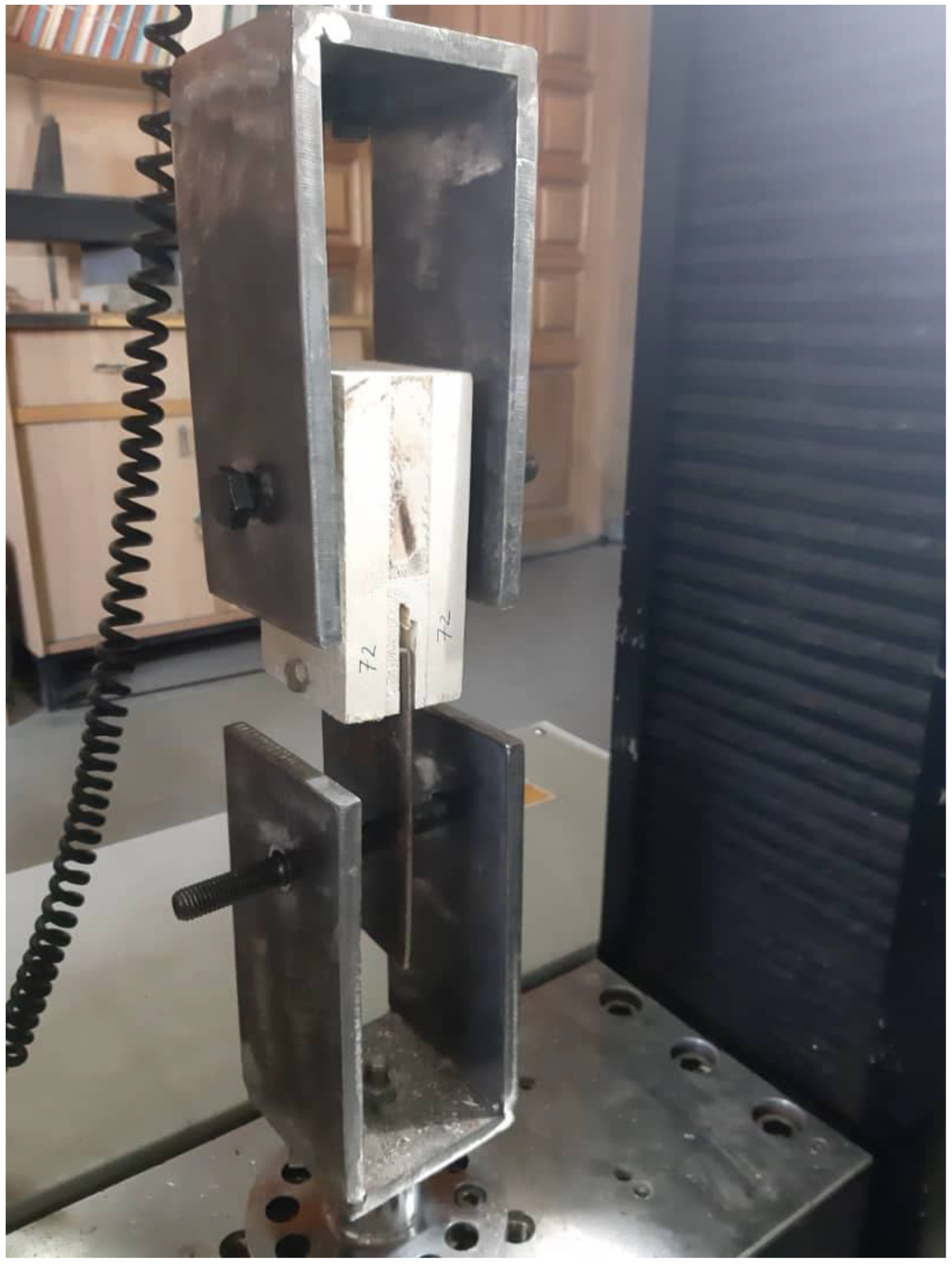
To measure the lateral resistance of the samples, CLT joints were tested by an Instron testing machine model 4486 (Figure 3) with the loading speed of 6 mm/min according to ASTM D 1037 [37].
Ductility is the ability of a material to survive in plastic deformation in which it can plastically deform without fracturing. Therefore, very ductile material shows high fracture strains.
Calculating the ductility was carried out by Equation (1):
δ = Δ u Δ p l
where Δ u and Δ p l are ultimate and proportional limit displacement, respectively.

2.4. Statistical Analysis

The data were statistically analyzed using the SPSS 25 program. Data obtained from the tests were statistically analyzed to report the main and interaction effects between the factors. In the first step, completely random design (Table 1) was applied to analyze the impact of GFRP layer number on lateral resistance. For the next step, data were analyzed based on the two-level factorial design (Table 2) to analyze the main and interaction effects of reinforcement, end distance, and panel strength direction on lateral resistance. Three replicates were considered for each group in all experimental tests. Duncan’s multiple range test was performed to assess the statistical differences between the means at a 95% confidence level.

3. Results and Discussion

3.1. Effect of GFRP Layer Number on Lateral Resistance

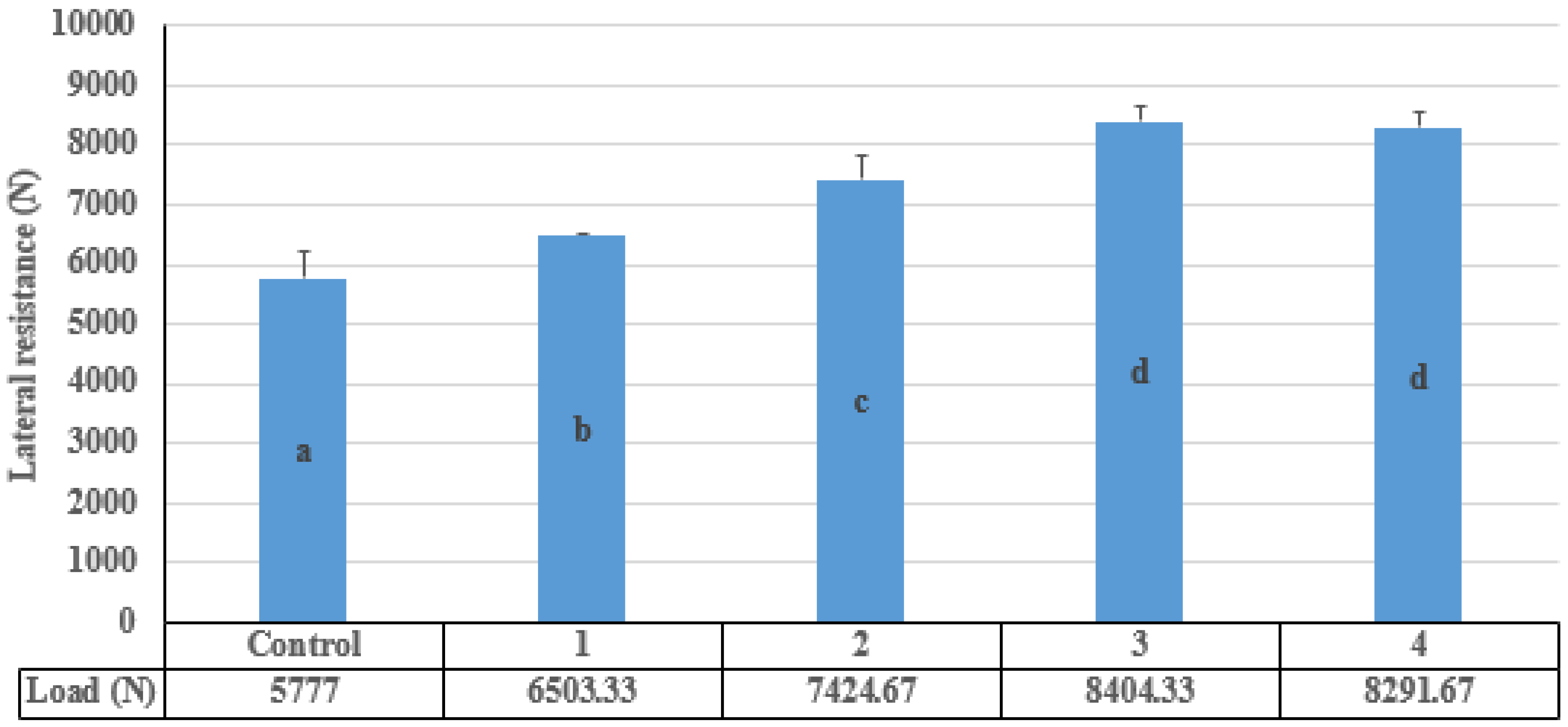
All numbers of the lateral load with the failure modes of the fasteners are listed in Table 5. As shown in Table 6, the effect of GFRP layer number on lateral resistance is statistically significant at a 99% confidence level. The results of the reinforced and non-reinforced CLTs under the lateral load are depicted in Figure 4. This test was carried out to find the best treatment for the following tests. Accordingly, non-reinforced specimens had the lowest lateral resistance (5777 N), while the specimens reinforced with three GFRP layers had the highest (8404.33 N). Moreover, there was a significant difference between reinforced CLT panels with one, two, and three GFRP layers and also non-reinforced, reinforced with one, two, and four GFRP layers. On the contrary, the was no significant difference between specimens reinforced with three and four layers of GFRP. As a result, reinforced CLT with three layers of GFRP was selected for the following investigations.
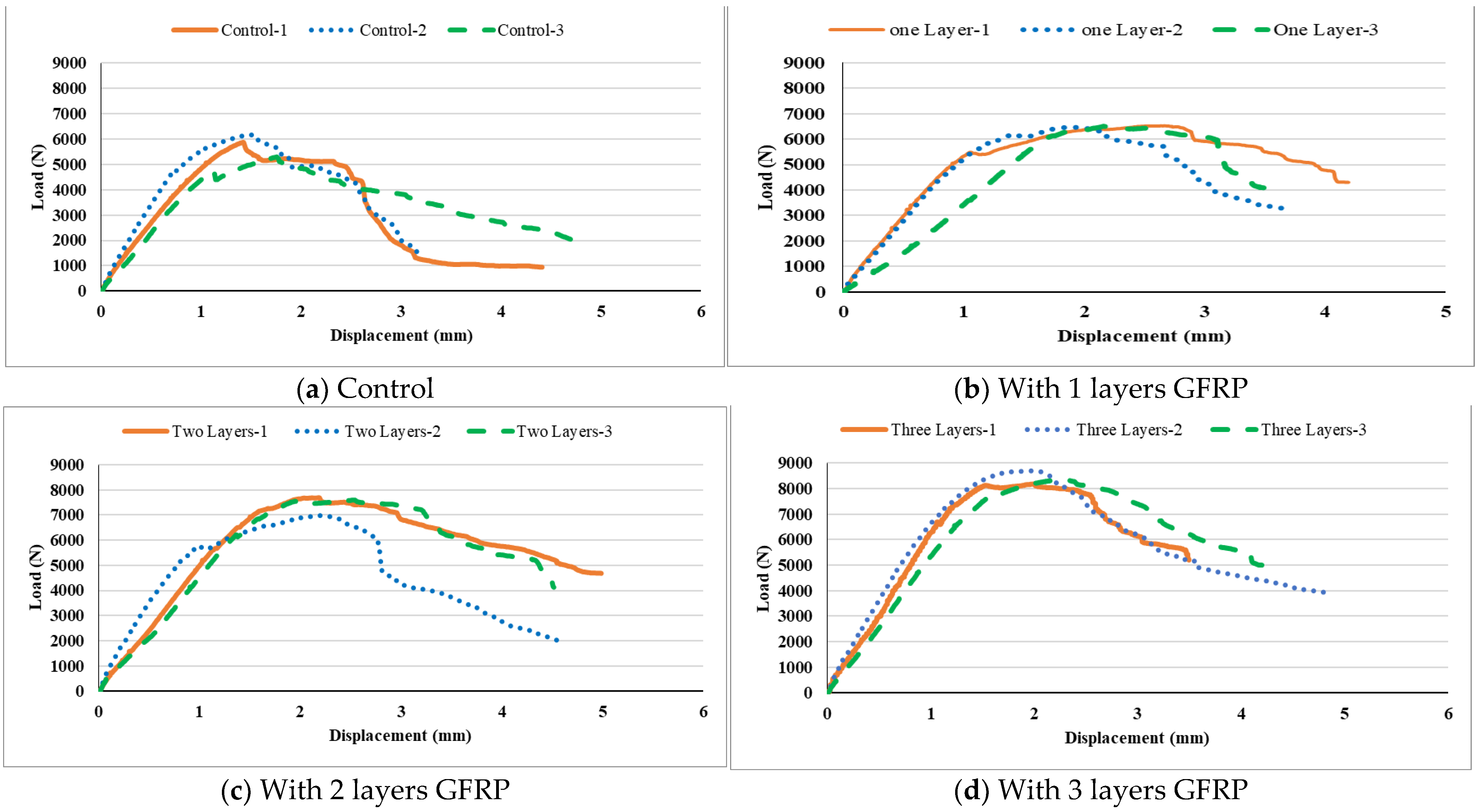
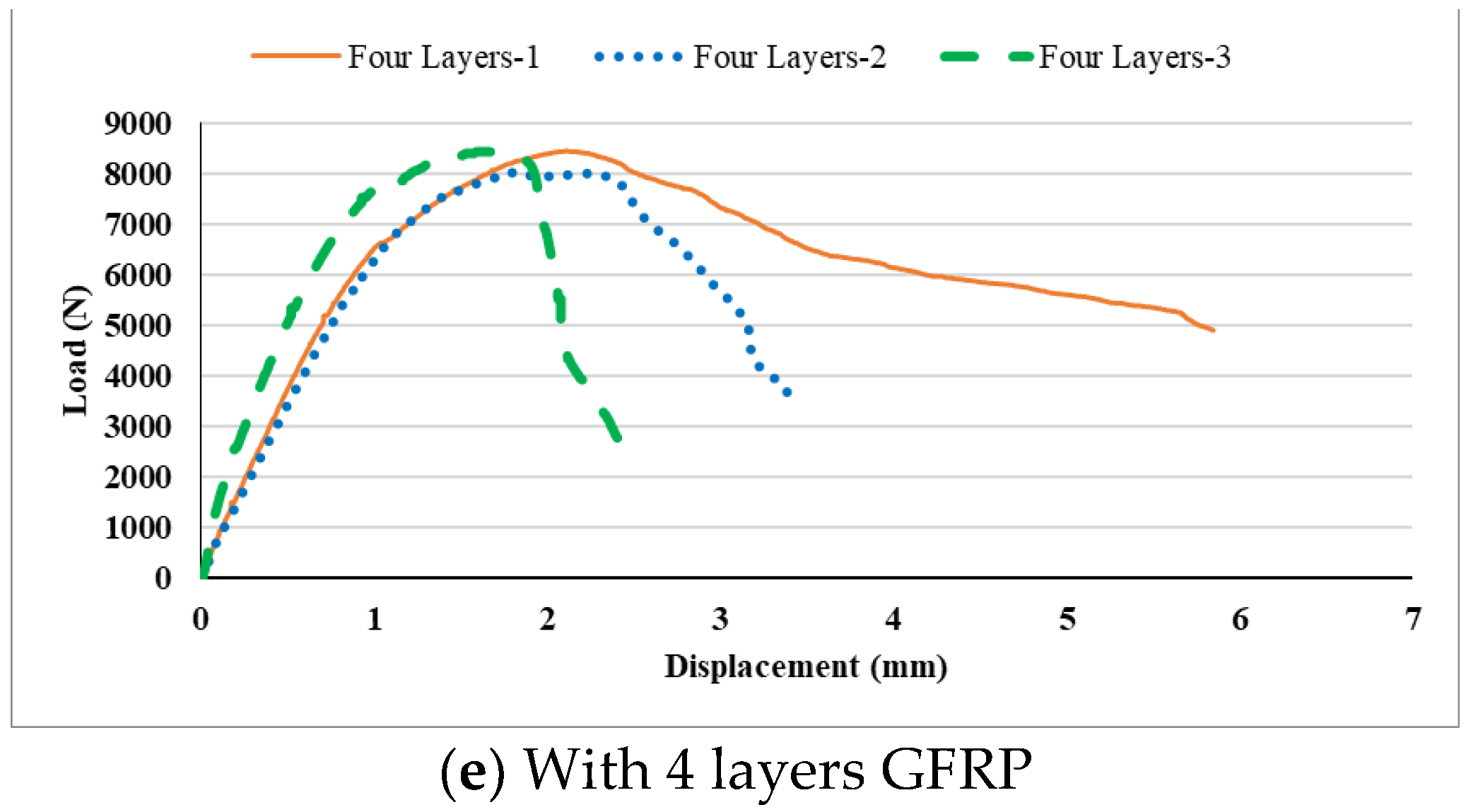
The load–displacement curves are depicted in Figure 5. Accordingly, by increasing the number of GFRP layers, the lateral resistance of the CLT samples increased. However, increasing the GFRP layer from three to four, the lateral resistance decreased slowly. In other words, by increasing the GFRP layer(s) from control samples to samples reinforced with one, two, three, and four layer(s), the lateral resistance was changed 13, 29, 45, and 44%, respectively. Figure 5 shows that lateral force resistance increased by reinforcing CLT with GFRP. In addition, it improved the deformation of CLT samples to some extent. In this regard, in the control samples, the highest load was observed in about one-millimeter displacement. However, in reinforced samples, the maximum force was observed at a displacement of about two millimeters. The results showed that the ductility was increased by 21.5%, 30%, 32.9%, and 24.8% with the increase in the number of GFRP layer(s) from one to two, three, and four compared to control specimens, respectively.

3.2. Effects of Reinforcement, End Distance, and Panel Strength Directions on Lateral Resistance

All numbers of the lateral load with the failure modes of the fasteners are listed in Table 7. Moreover, the main and interaction effects of reinforcement, panel strength direction, and end distance of the fastener on the lateral resistance of the CLT joints are shown in Table 8. The findings revealed that, while the main effect of the reinforcement and end distance was significant on the lateral resistance of the CLTs, the main effect of the panel strength directions was not significant. Additionally, while the interaction effects of reinforcement * panel strength directions * end distance and reinforcement * panel strength directions * end distance was not significant, the interaction effect of reinforcement * end distance was significant.
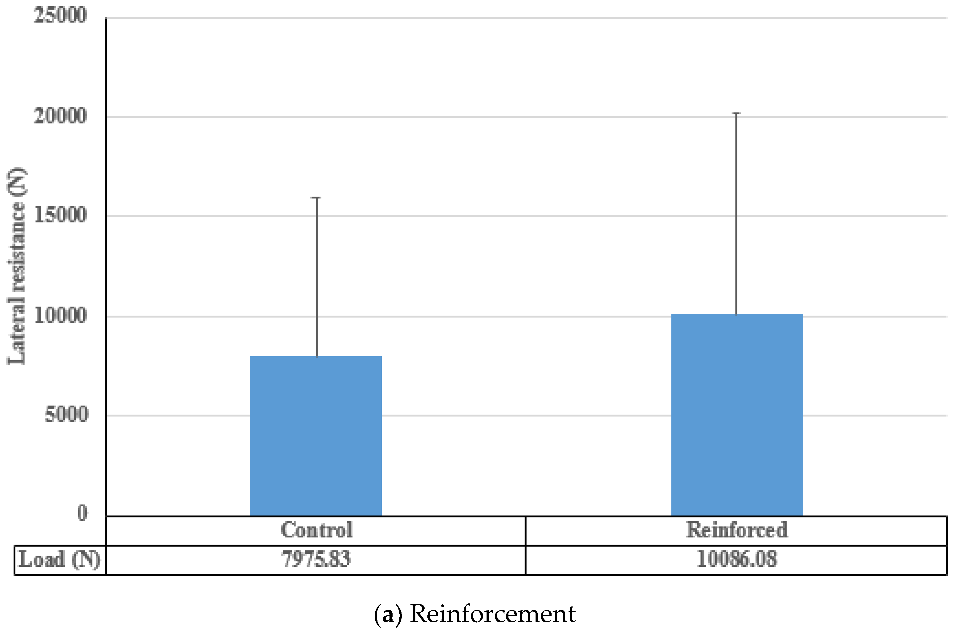
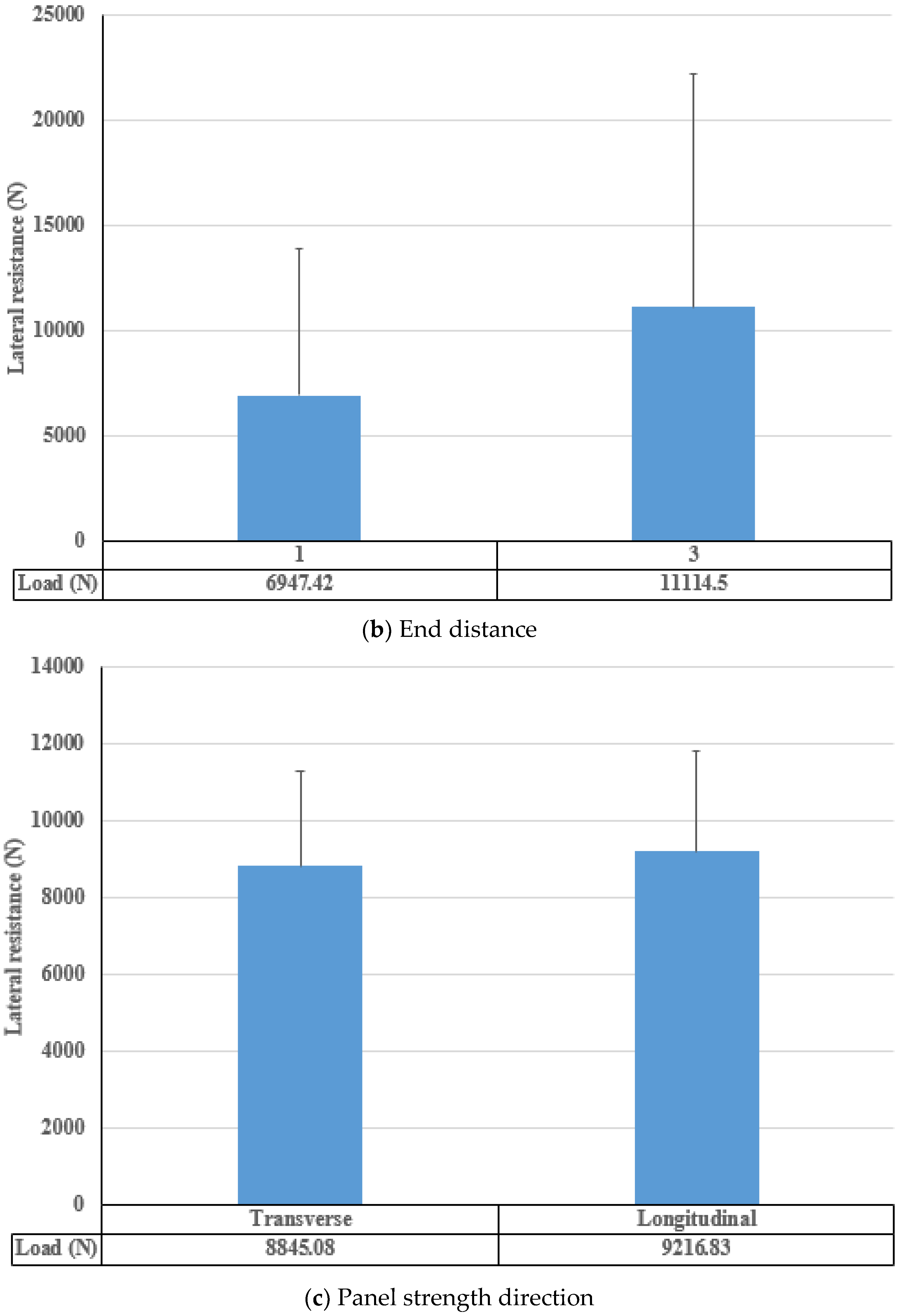
The main effect of reinforcement, panel strength direction, and end distance on the lateral resistance of CLTs is shown in Figure 6a–c. The results indicated that reinforcement significantly increased the lateral resistance of the CLT specimens by 26.45% (Figure 6a). Additionally, by increasing the end distance from 1 cm to 3 cm, the lateral resistance of the CLT increased significantly by 60% (Figure 6b). On the other hand, panel strength direction had no significant impact (about 4%) on the lateral resistance of the CLT specimens (Figure 6c).
Figure 7a presents the interaction effect between panel strength direction and reinforcement in the CLT specimens. According to the results, the highest lateral resistance was observed in the reinforced CLTs in the longitudinal direction (10,275.83 N). In contrast, the lowest was observed in the transverse direction of the control samples (7793.83 N), where no significant difference was observed between the groups in this interaction. The lateral resistance of CLT was changed by 31.85% with the change in panel strength direction and reinforcement.
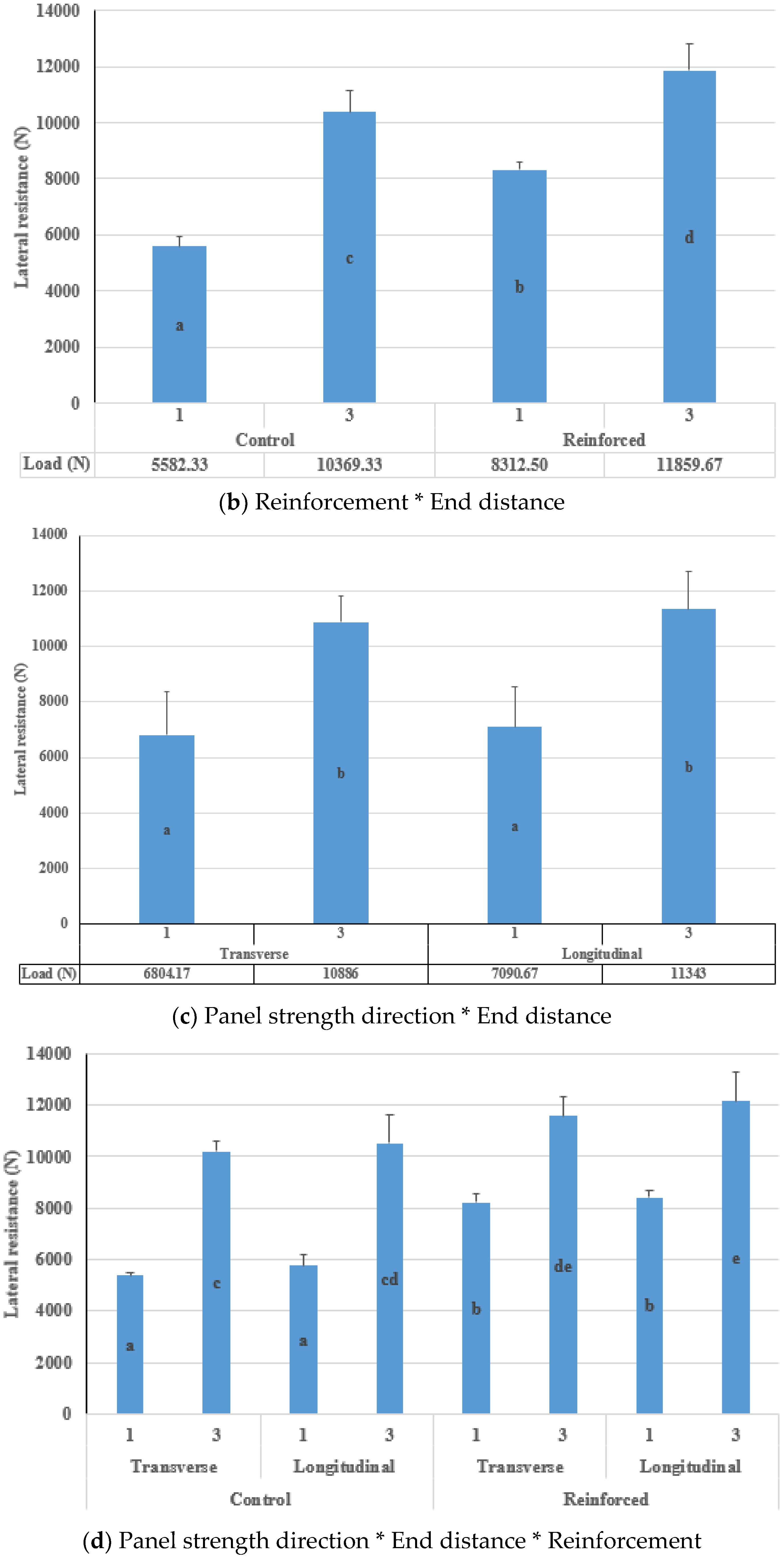
Figure 7b shows the interaction effect between reinforcement and end distance. The findings revealed that there was a significant difference between the groups. The minimum lateral resistance was in the control sample at the end distance of 1 cm (5582.33 N), whilst the maximum was related to the reinforced CLT samples in the longitudinal direction (11,859.67 N), which was 112.45%. Therefore, with an increase in end distance from 1 to 3 cm, lateral resistance was increased by 42.7% and 85.7% for reinforced and unreinforced CLT panels. The results were in good agreement with previous studies, which reported reinforcement with GFRP enhanced the properties of wood and wood-based products, such as CLT [20,21,22].
The interaction effect between panel strength direction and end distance is depicted in Figure 7c. No significant difference was observed between the end distance of 1 cm in the two-panel strength directions of the panel. It was the same for the 3 cm end distance. The lag screw at the end distance of 1 cm in transverse arrangement showed the lowest lateral resistance (6804.17 N), while it was highest at the end distance of 3 cm in longitudinal arrangement (11,343 N), which changed 66.7%.
The interaction effect between panel strength direction, end distance, and reinforcement is depicted in Figure 7d. Accordingly, no significant difference was observed between the transverse and longitudinal arrangements at the end distance of 1 cm in the control samples. The same results were obtained for the reinforced samples. Moreover, for the end distance of 3 cm, no significant difference was observed in the longitudinal direction for the control sample; the same results were obtained for the reinforced samples. The findings revealed that the percentage of increase in lateral resistance of CLT joints by reinforcement at the end distance of 1 cm is much higher than the those in joints with the end distance of 3 cm so that, in the transverse direction with reinforcement, the lateral resistance at the end distances of 1 and 3 cm was increased 52.6 and 13.5%, respectively. Their corresponding increase in the longitudinal direction of the panel for the end distances of 1 and 3 cm was 45.5% and 15.3%, respectively.

4. Failure Modes

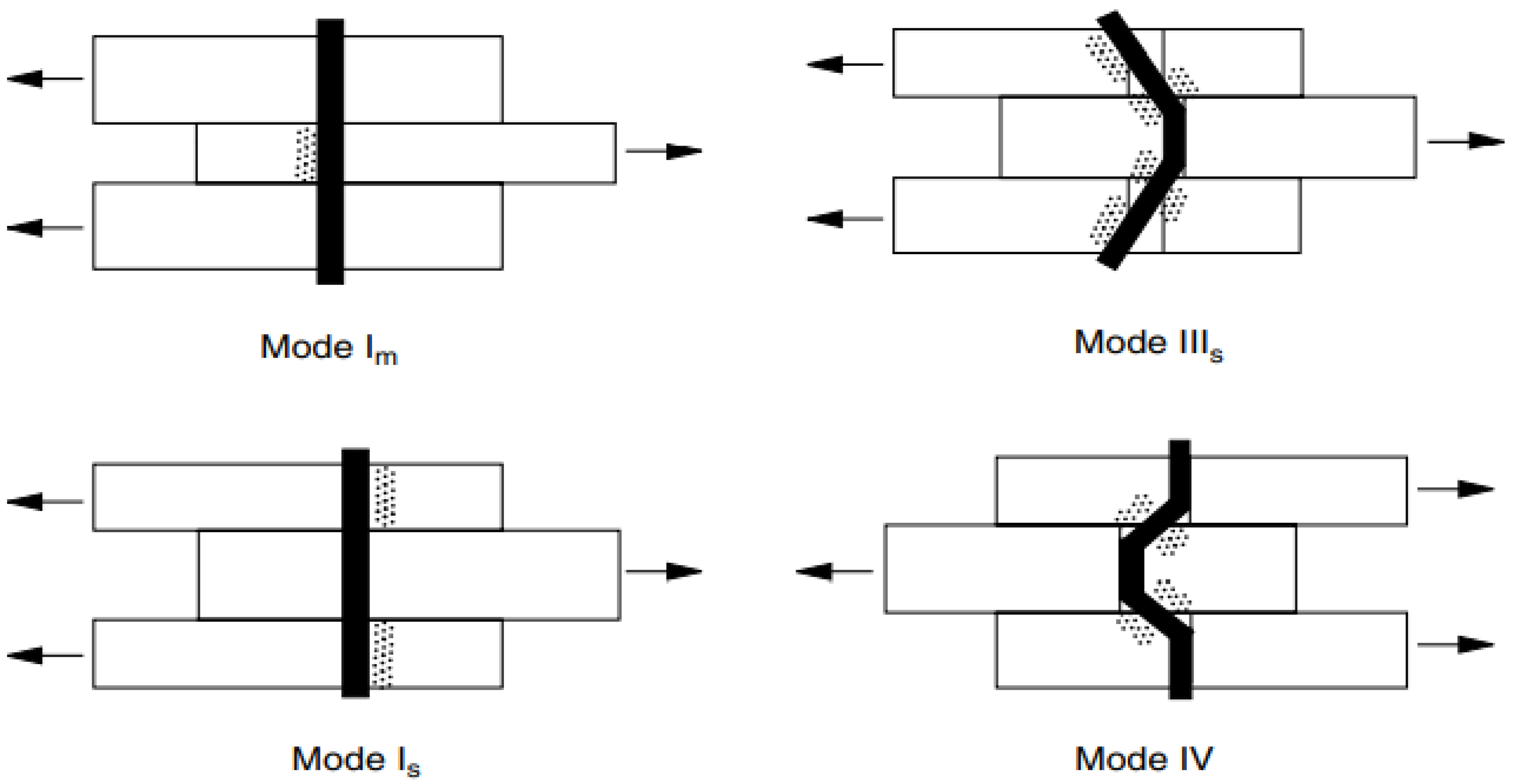
Figure 8 and Figure 9 provide a schematic of the various failure mechanisms of fasteners and CLT members of joints under lateral load. As illustrated in Figure 8, wood members and orthotropic materials are more prone to showing a, b, and c modes or a mixture of them. Shear and bearing failure modes (Figure 8b,c) occur when force is applied laterally parallel to the grain of the wood part. However, when the force is applied laterally perpendicular to the grain of the wood component, the net-tension failure mode (Figure 8a) occurs. In this investigation, all failure mechanisms of double shear plane CLT joints under lateral force occurred in fasteners and CLT members rather than the metal connector due to their high bearing strength. It is unavoidable to investigate the failure mechanisms of fasteners and CLT members. The net-tension mode showed little lateral resistance, but the bearing and shear modes showed more lateral resistance.
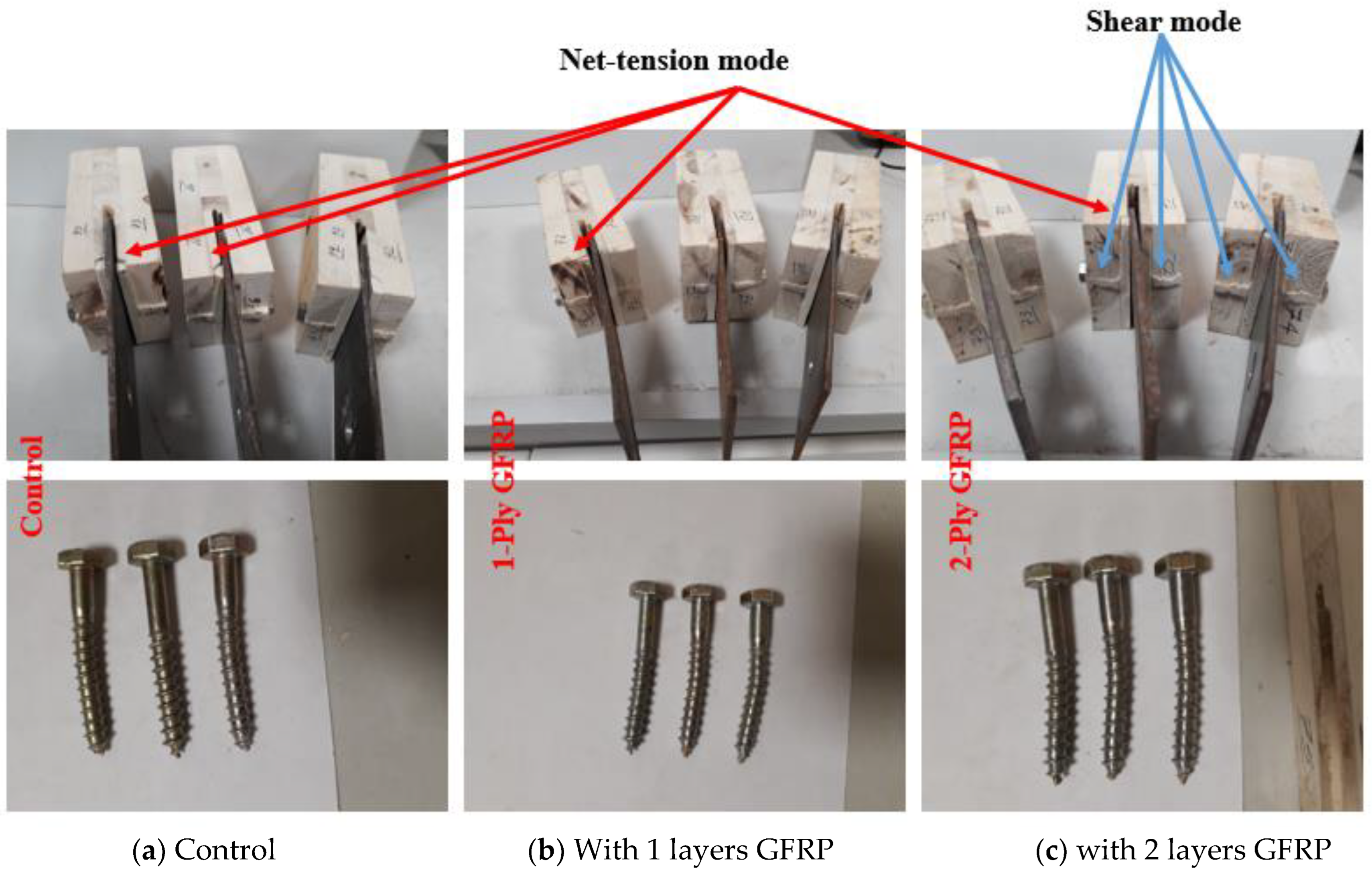
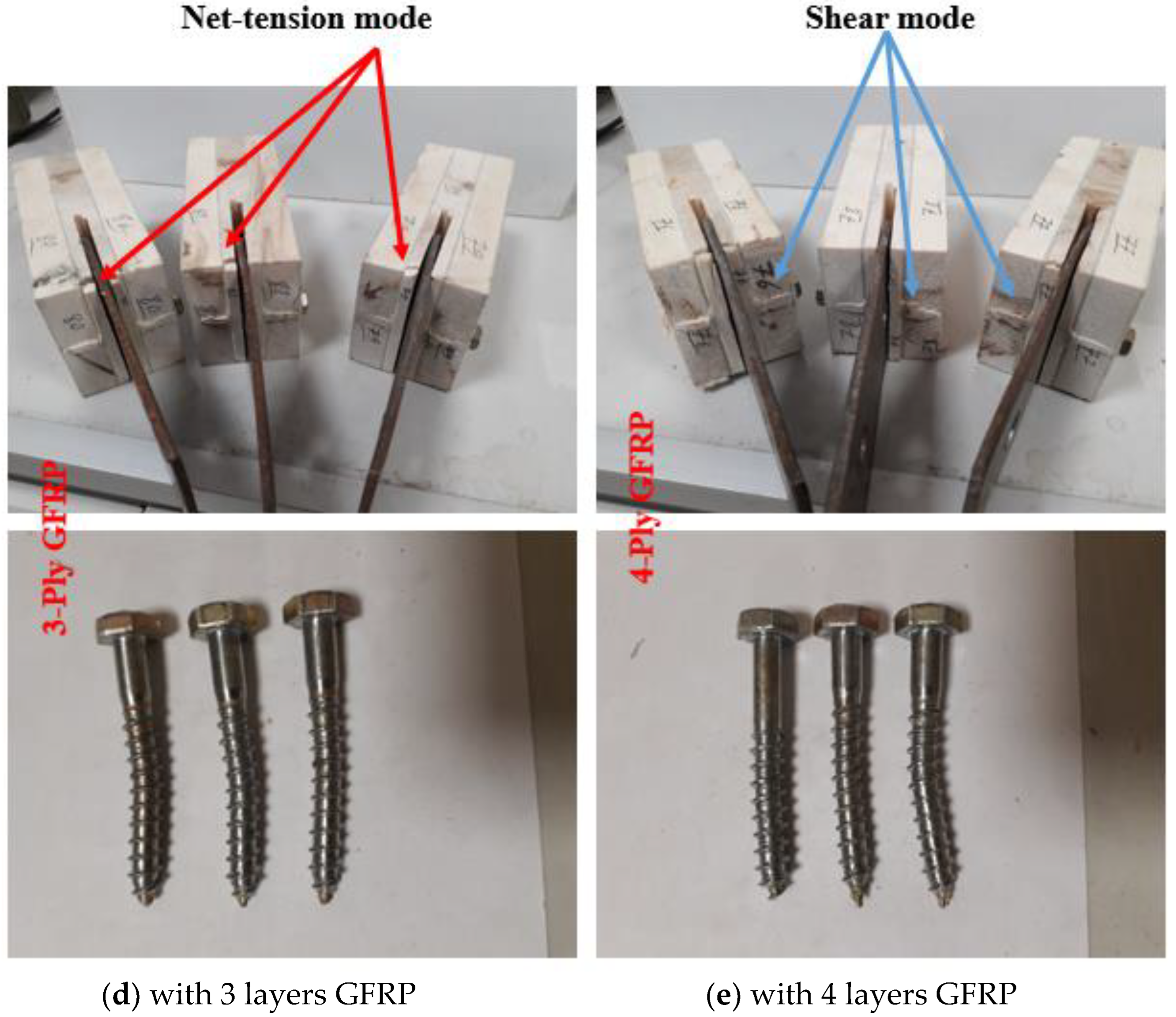
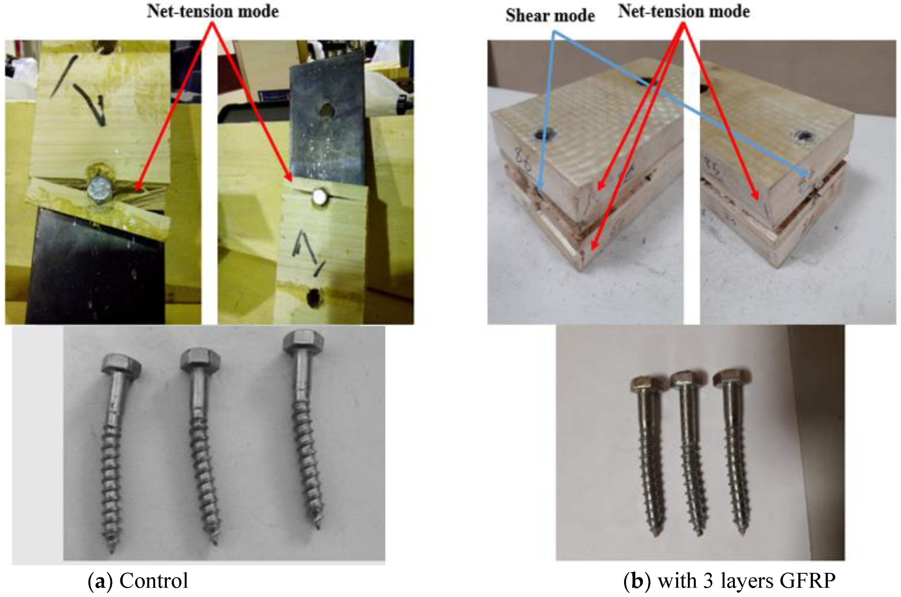
First, CLT specimens were laterally loaded to determine the maximum lateral resistance in the GFRP layer. In this regard, control and reinforced samples with one, two, three, or four GFRP layer(s) were laterally loaded at a 1 cm end distance (critical point). Figure 9 depicts the relevant failure scenarios of the fastener in double shear lap joints. Lag screws failed in Is and IIIs modes. However, the CLT panel planks failed in the bearing, shear, and net-tension modes. As previously stated, the CLT samples reinforced with three GFRP layers produced the greatest results. Lag screws in reinforced samples exhibited more lateral resistance than controls. According to Figure 10 and Figure 11, reinforced samples failed under lateral load slightly less than control samples, indicating more resistance than the control samples. However, fasteners deformation occurred more in the reinforced samples than in control samples.
When the CLTs in the major axis were laterally loaded, the upmost and bottommost layers failed with the shear mode, while the middle layer failed with the net-tension mode. At the end distance of 1 cm, the shear failure mode in the reinforced CLT samples was slightly less than in the control samples (Figure 10). This means that GFRP improved the strength of CLTs under the lateral load. Regarding the fastener failure mode, the common failure mode was Is in the control samples, whereas it was IIIs in the reinforced samples (Figure 10). IIIs mode shows more deformation in fasteners under the lateral load, meaning more force to deform the fasteners.
Finally, CLT samples reinforced with three GFRP layers as high-strength joint members were selected for subsequent investigations.
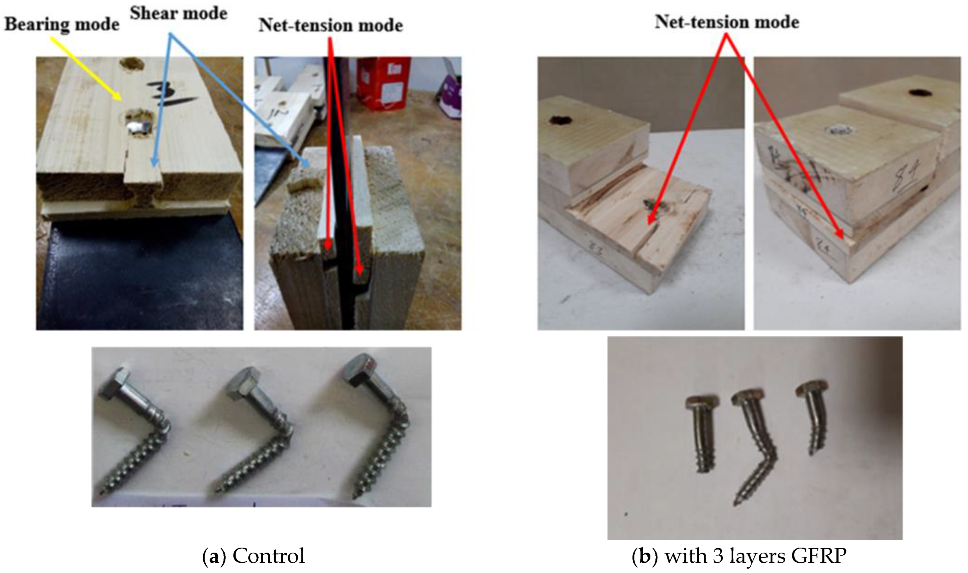
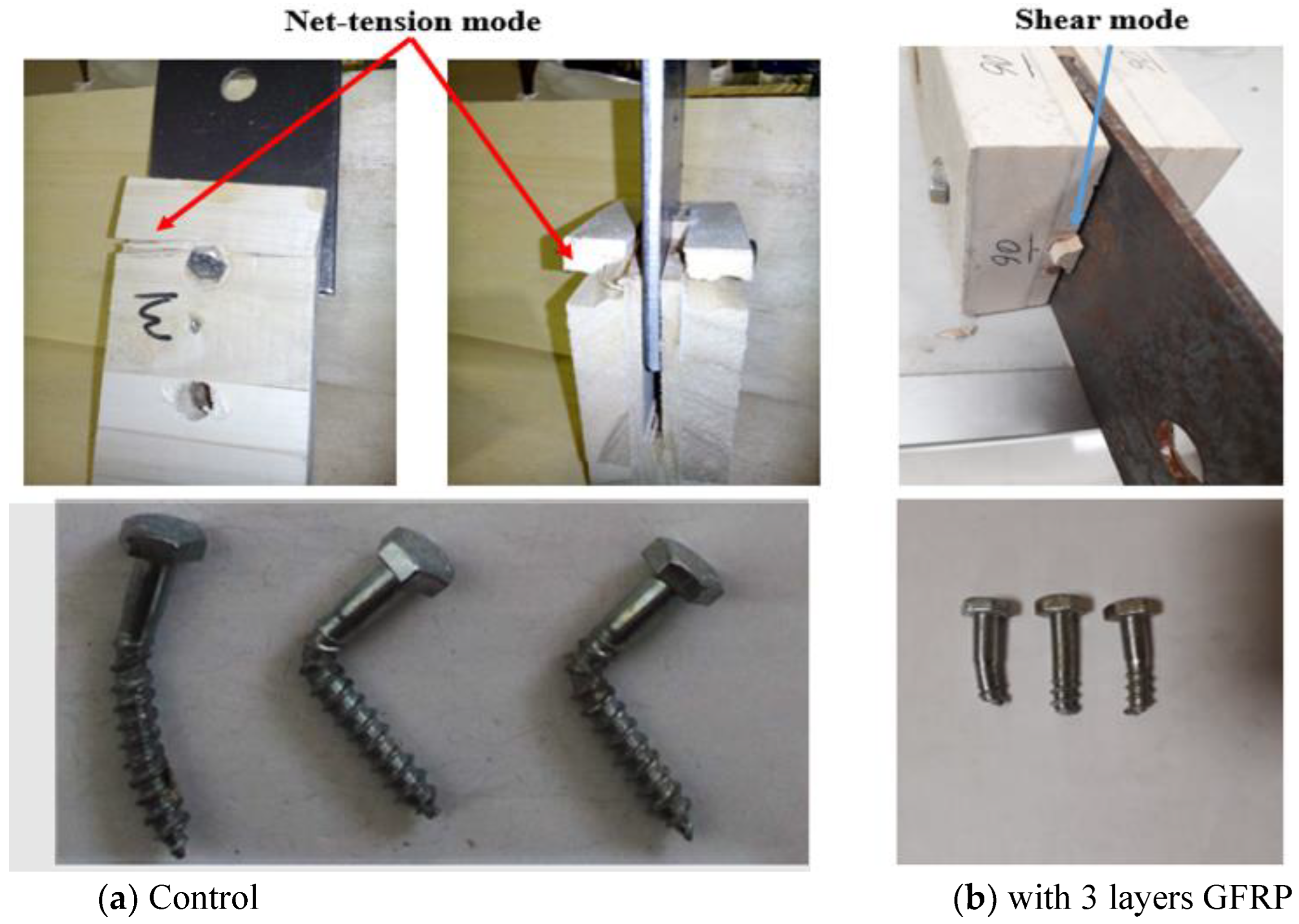
At the end distance of 3 cm in the major axis of the CLTs, the control samples failed with bearing, shear, and net tension modes (Figure 11). The upmost and bottommost layers of unreinforced CLT failed with bearing and shear modes, and the middle layer failed with net-tension mode. However, compared to the end distance of 1 cm, no failure mode was observed in the upmost and bottommost layers due to the increased end distance from 1 to 3 cm, especially in reinforced CLT members. Moreover, at the end distance of 3 cm, just the net-tension mode was observed at the middle layer of the reinforced CLT member. This means that reinforcement enhanced the lateral resistance of CLTs. Regarding the failure modes of the fastener, in this direction and at the end distance of 3 cm, lag screws failed with the IIIs and IV modes. In control samples, IIIs was a common mode, while IV was the common mode in reinforced samples. Since the reinforced CLTs tolerate high lateral load, the stress is distributed on lag screws so that they shear from the shank (Figure 11 and Figure 12). The results concur well with those obtained by Oh et al. [29], Chen et al. [40], Mohamadzadeh et al. [41], and Rostampour-Haftkhani et al. [42].
The failure mode of lag screws and CLT members in the minor axis at the end distance of 1 cm is depicted in Figure 12. Accordingly, in both reinforced and control samples, net-tension and shear modes were common in CLT members. The upmost and bottommost layers failed with the net-tension mode in both CLTs, while the middle layer failed with the shear mode. The failure modes in the reinforced samples were slighter than in the control samples, meaning high lateral resistance of reinforced CLT samples. In terms of the failure modes of the fasteners, Is and IIIs were the common failure modes. None of the lag screws sheared from the shank in this direction at the end distance of 1 cm. Contrary to CLT joints with 3 cm end distance, all the CLT layers in this direction failed. In other words, they failed easily under the lateral load, resulting in low deformation in lag screws.
The failure modes of lag screws and CLT samples on the minor axis at the end distance of 3 cm are depicted in Figure 13. Accordingly, the upmost and bottommost layers failed with net-tension mode, while the middle one failed with shear mode. In the reinforced samples, the failures were slighter than the control samples, showing more resistance under the lateral load. Moreover, by increasing the end distance, the lateral resistance increased. According to Brown and Li [30], CLT connection ductility and displacement capabilities were increased as end distance increased.

5. Conclusions

The impacts of reinforcement with GFRP on the lateral resistance of double shear lap joints in CLTs made of poplar were investigated. These results might be useful for manufacturing timber bridges.
-
As the number of layers to reinforce the CLT increased from one to three, the lateral resistance of the fastener increased significantly. However, the lateral resistance of the fastener decreased as the number of layers to reinforce the CLT increased from three to four.
-
Examining the effect of reinforcement with GFRP, end distance, and panel strength direction on the lateral resistance revealed that the end distance has a meaningful effect. By reinforcing the CLT with the GFRP, increasing the end distance, and changing the panel strength direction, the values of lateral resistance changed to 26.45, 60, and 4.2%, respectively.
-
In reinforcement CLT panels, lateral resistance of joints was changed slightly by increasing end distance; however, it was increased drastically in unreinforced CLT with the increase in end distance.
-
The failure modes study indicated that specimens in which the fastener did not have a plastic deformation but the CLT member failed more severely showed less resistance. With the reinforcement of the CLT, the fracture intensity in the CLT member decreased, which indicated their excellent resistance. Those specimens showed very high resistance in which the screw was sheared in the interface between wood and steel plate, which was observed mainly in reinforced specimens, especially those with higher end distance. Consequently, GFRP is recommended for reinforcing CLTs under the lateral load, especially in the connection spots.
-
These findings could be useful in designing the connectors, such as angle brackets, since these types of connectors are exposed to the lateral loads when they apply to the timber structures.

Author Contributions

Conceptualization, A.R.H. and F.A.; methodology, A.R.H.; software, A.R.H.; validation, M.R., F.A. and M.G.; formal analysis, A.R.H.; investigation, M.R.; resources, A.R.H.; data curation, M.G.; writing—original draft preparation, F.A.; writing—review and editing, A.R.H., M.R.; visualization, M.G.; supervision, M.R.; project administration, F.A.; funding acquisition, M.R. All authors have read and agreed to the published version of the manuscript.

Funding

This research received no external funding.

Conflicts of Interest

The authors declare no conflict of interest.

References

  1. Rashidi, M.; Hoshyar, A.N.; Smith, L.; Samali, B.; Siddique, R. A comprehensive taxonomy for structure and material deficiencies, preventions and remedies of timber bridges. J. Build. Eng. 2021, 34, 101624. [Google Scholar] [CrossRef]
  2. North, M. Spreading the load: The management of heritage timber truss bridges in the NSW road network. Aust. J. Multi-Discip. Eng. 2012, 9, 79–85. [Google Scholar] [CrossRef]
  3. Rashidi, M.; Zhang, C.; Ghodrat, M.; Kempton, S.; Samali, B.; Akbarnezhad, A.; Zhu, L. Bridge abutment movement and approach settlement—A case study and scenario analysis. Int. J. Struct. Stab. Dyn. 2018, 18, 1840011. [Google Scholar] [CrossRef]
  4. Franke, S.; Franke, B.; Harte, A.M. Failure modes and reinforcement techniques for timber beams–State of the art. Constr. Build. Mater. 2015, 97, 2–13. [Google Scholar] [CrossRef]
  5. Canbek, C.; Mirmiran, A.; Chowdhury, A.G.; Suksawang, N. Development of fiber-reinforced polymer roof-to-wall connection. J. Compos. Constr. 2011, 15, 644–652. [Google Scholar] [CrossRef]
  6. Lukaszewska, E.; Fragiacomo, M.; Johnsson, H. Laboratory tests and numerical analyses of prefabricated timber-concrete composite floors. J. Struct. Eng. 2010, 136, 46–55. [Google Scholar] [CrossRef]
  7. Saribiyik, M.; Akguuml, T. GFRP bar element to strengthen timber connection systems. Sci. Res. Essays 2010, 5, 1713–1719. [Google Scholar]
  8. Nie, Y.; Valipour, H. Experimental and numerical study of long-term behaviour of timber-timber composite (TTC) connections. Constr. Build. Mater. 2021, 304, 124672. [Google Scholar] [CrossRef]
  9. Miotto, J.L.; Dias, A.A. Evaluation of perforated steel plates as connection in glulam–concrete composite structures. Constr. Build. Mater. 2012, 28, 216–223. [Google Scholar] [CrossRef]
  10. Clouston, P.; Bathon, L.A.; Schreyer, A. Shear and bending performance of a novel wood–concrete composite system. J. Struct. Eng. 2005, 131, 1404–1412. [Google Scholar] [CrossRef] [Green Version]
  11. Otero-Chans, D.; Estévez-Cimadevila, J.; Suárez-Riestra, F.; Martin-Gutierrez, E. Experimental analysis of glued-in steel plates used as shear connectors in Timber-Concrete-Composites. Eng. Struct. 2018, 170, 1–10. [Google Scholar] [CrossRef]
  12. Chybiński, M.; Polus, Ł. Mechanical behaviour of aluminium-timber composite connections with screws and toothed plates. Materials 2021, 15, 68. [Google Scholar] [CrossRef] [PubMed]
  13. Morales-Conde, M.; Rodríguez-Liñán, C.; Rubio-de Hita, P. Bending and shear reinforcements for timber beams using GFRP plates. Constr. Build. Mater. 2015, 96, 461–472. [Google Scholar] [CrossRef]
  14. Raftery, G.M.; Whelan, C. Low-grade glued laminated timber beams reinforced using improved arrangements of bonded-in GFRP rods. Constr. Build. Mater. 2014, 52, 209–220. [Google Scholar] [CrossRef]
  15. Hollaway, L.C.; Teng, J.-G. Strengthening and Rehabilitation of Civil Infrastructures Using Fibre-Reinforced Polymer (FRP) Composites; Elsevier: Amsterdam, The Netherlands, 2008. [Google Scholar]
  16. Bank, L.C. Composites for Construction: Structural Design with FRP Materials; John Wiley & Sons: Hoboken, NJ, USA, 2006. [Google Scholar]
  17. Karbhari, V.M. Introduction: The use of composites in civil structural applications. In Durability of Composites for Civil Structural Applications; Elsevier: Amsterdam, The Netherlands, 2007; pp. 1–10. [Google Scholar]
  18. Madhoushi, M.; Ansell, M.P. Effect of glue-line thickness on pull-out behavior of glued-in GFRP rods in LVL: Finite element analysis. Polym. Test. 2017, 62, 196–202. [Google Scholar] [CrossRef] [Green Version]
  19. Song, X.; Ma, Y.; Gu, X.; Wang, M. Carbon fiber–reinforced polymer reinforcement for rotational behavior of bolted glulam beam-to-column connections. J. Compos. Constr. 2017, 21, 04016096. [Google Scholar] [CrossRef]
  20. Gómez, S.; Svecova, D. Behavior of split timber stringers reinforced with external GFRP sheets. J. Compos. Constr. 2008, 12, 202–211. [Google Scholar] [CrossRef]
  21. Hay, S.; Thiessen, K.; Svecova, D.; Bakht, B. Effectiveness of GFRP sheets for shear strengthening of timber. J. Compos. Constr. 2006, 10, 483–491. [Google Scholar] [CrossRef]
  22. Skinner, J.; Salisbury, E.; Harris, R. GFRP connectors for thin topping timber-concrete composites. Eur. J. Wood Wood Prod. 2016, 74, 477–479. [Google Scholar] [CrossRef]
  23. Wu, C.; Zhang, Z.; Tam, L.-h.; Feng, P.; He, L. Group effect of GFRP-timber bolted connections in tension. Compos. Struct. 2021, 262, 113637. [Google Scholar] [CrossRef]
  24. Hadigheh, S.; McDougall, R.; Wiseman, C.; Reid, L. Evaluation of composite action in cross laminated timber-concrete composite beams with CFRP reinforcing bar and plate connectors using Digital Image Correlation (DIC). Eng. Struct. 2021, 232, 111791. [Google Scholar] [CrossRef]
  25. Joyce, T.P. Connections for CLT Diaphragms in Steel-Frame Buildings; University of New Brunswick: Fredericton, NB, Canada, 2014. [Google Scholar]
  26. Ringhofer, A.; Brandner, R.; Blaß, H.J. Cross laminated timber (CLT): Design approaches for dowel-type fasteners and connections. Eng. Struct. 2018, 171, 849–861. [Google Scholar] [CrossRef]
  27. Hossain, A.; Danzig, I.; Tannert, T. Cross-laminated timber shear connections with double-angled self-tapping screw assemblies. J. Struct. Eng. 2016, 142, 04016099. [Google Scholar] [CrossRef]
  28. Wadi, H.; Amziane, S.; Taazount, M. The lateral load resistance of unclassified cross-laminated timber walls: Experimental tests and theoretical approach. Eng. Struct. 2018, 166, 402–412. [Google Scholar] [CrossRef]
  29. Oh, J.-K.; Kim, G.-C.; Kim, K.-M.; Lee, J.-J.; Hong, J.-P. End distance of single-shear screw connection in cross laminated timber. J. Korean Wood Sci. Technol. 2017, 45, 746–752. [Google Scholar] [CrossRef]
  30. Brown, J.R.; Li, M. Structural performance of dowelled cross-laminated timber hold-down connections with increased row spacing and end distance. Constr. Build. Mater. 2021, 271, 121595. [Google Scholar] [CrossRef]
  31. Liu, Y.; Yao, Z.; Wang, F.; Huang, H.; Que, Z. Effect of arrangement distances on stiffness of shear-tension mode in timber-to-timber connections with inclined screws. Constr. Build. Mater. 2022, 314, 125592. [Google Scholar] [CrossRef]
  32. Ruan, G.; Filz, G.H.; Fink, G. Shear capacity of timber-to-timber connections using wooden nails. Wood Mater. Sci. Eng. 2022, 17, 20–29. [Google Scholar] [CrossRef]
  33. Fonseca, E.M.; Leite, P.A.; Silva, L.D.; Silva, V.S.; Lopes, H.M. Parametric Study of Three Types of Timber Connections with Metal Fasteners Using Eurocode 5. Appl. Sci. 2022, 12, 1701. [Google Scholar] [CrossRef]
  34. Bhat, J. Improved strength and stiffness characteristics of cross-laminated poplar timber columns. Int. J. Eng. 2021, 34, 803–810. [Google Scholar]
  35. Karacabeyli, E.; Gagnon, S. Canadian CLT Handbook, 2019th ed.; Digital; FPInnovations: Pointe-Claire, QC, Canada, 2019. [Google Scholar]
  36. Abdoli, F.; Rashidi, M.; Rostampour-Haftkhani, A.; Layeghi, M.; Ebrahimi, G. Withdrawal Performance of Nails and Screws in Cross-Laminated Timber (CLT) Made of Poplar (Populus alba) and Fir (Abies alba). Polymers 2022, 14, 3129. [Google Scholar] [CrossRef] [PubMed]
  37. ASTM, D. 1037; Standard Methods of Evaluating the Properties of Wood-Base Fiber and Particle Panel Materials. American Society for Testing and Materials: West Conshohocken, PA, USA, 1999.
  38. Sharos, P.A. Efficient Load Distribution Analysis and Strength Prediction of Bolted Composite Joints at Various Loading Rates. Ph.D. Thesis, University of Limerick, Limerick, Ireland, 2016. [Google Scholar]
  39. Williamson, T.G. APA Engineered Wood Handbook; McGraw Hill Professional: New York, NY, USA, 2002. [Google Scholar]
  40. Chen, G.; Jiang, H.; Yu, Y.-f.; Zhou, T.; Wu, J.; Li, X. Experimental analysis of nailed LBL-to-LBL connections loaded parallel to grain. Mater. Struct. 2020, 53, 1–13. [Google Scholar] [CrossRef]
  41. Mohamadzadeh, M.; Haftkhani, A.R.; Ebrahimi, G.; Yoshihara, H. Numerical and experimental failure analysis of screwed single shear joints in wood plastic composite. Mater. Des. 2012, 35, 404–413. [Google Scholar] [CrossRef]
  42. Haftkhani, A.R.; Ebrahimi, G.; Tajvidi, M.; Layeghi, M.; Arabi, M. Lateral resistance of joints made with various screws in commercial wood plastic composites. Mater. Des. 2011, 32, 4062–4068. [Google Scholar] [CrossRef]
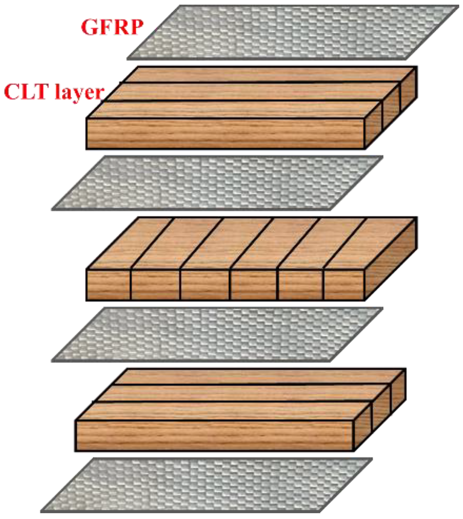
Figure 1. Schematic of adding GFRP to CLT samples.
Buildings 12 01678 g001
Figure 2. Placement of metal connector and fastener in CLT specimens.
Buildings 12 01678 g002
Figure 3. Lateral resistance set-up by Instron machine.
Buildings 12 01678 g003
Figure 4. Number of GFRP layers.
Buildings 12 01678 g004
Figure 5. Load–displacement curves of the reinforced CLT samples with various GFRP layers.
Buildings 12 01678 g005aBuildings 12 01678 g005b
Figure 6. Main effects of reinforcement, end distance, and panel strength directions on lateral resistance.
Buildings 12 01678 g006aBuildings 12 01678 g006b
Figure 7. Interaction effects of reinforcement, end distance, and panel strength directions on lateral resistance.
Buildings 12 01678 g007aBuildings 12 01678 g007b
Figure 8. Possible failure modes of joint members under the lateral load: (a) net-tension, (b) shear, (c) bearing [38].
Buildings 12 01678 g008
Figure 9. Failure mode of the fasteners under the lateral load [39].
Buildings 12 01678 g009
Figure 10. Failure modes of control and reinforced samples with 1, 2, 3, and 4 layers of GFRP, and lag screws at the end distance of 1 cm in major axis of CLT panel.
Buildings 12 01678 g010aBuildings 12 01678 g010b
Figure 11. Failure modes of control and reinforced samples, and lag screws at the end distance of 3 cm in major axis of CLT panel.
Buildings 12 01678 g011
Figure 12. Failure modes of control and reinforced samples, and lag screws at the end distance of 1 cm in minor axis of CLT panel.
Buildings 12 01678 g012
Figure 13. Failure modes of control and reinforced samples, and lag screws at the end distance of 3 cm in minor axis of CLT panel.
Buildings 12 01678 g013
Table 1. Statistical groups for investigating the effect of GFRP layer number on lateral resistance.
Statistical DesignPanel DirectionGFRP Layer NumberEnd Distance (cm)Replicate
Completely randomMajor axisUnreinforced13
Major axis113
Major axis213
Major axis313
Major axis413
Table 2. Statistical groups for investigating the effect of reinforcement, end distance, and panel strength direction on lateral resistance.
Statistical DesignCLTPanel DirectionEnd Distance (cm)Replicate
Two-level factorialReinforced with 3 GFRP layersMajor axis1 3
Reinforced with 3 GFRP layersMajor axis33
Reinforced with 3 GFRP layersMinor axis1 3
Reinforced with 3 GFRP layersMinor axis33
UnreinforcedMajor axis1 3
UnreinforcedMajor axis33
UnreinforcedMinor axis1 3
UnreinforcedMinor axis33
Table 3. Characteristics of GFRP.
Thickness (mm)Weight (gr/m2)Modulus of Elasticity (MPa)Tensile Strength (MPa)
0.236600902300
Table 4. Properties of lag screw (8 mm) [36].
Lag screw
(8 mm)
Buildings 12 01678 i001
Neck length (mm)65.5
Major diameter (mm)7.75
Minor
diameter (mm)
5.6
Pre-drilled hole diameter (mm)5
Metal connector hole diameter (mm)8
Table 5. The lateral load and failure modes of the screw.
Panel DirectionGFRP Layer NumberEnd Distance (cm)Lateral Load (N)Ductility
δ (mm/mm)
Failure Mode of Screw
Major axisUnreinforced158711.37Is (common) and IIIs
Major axisUnreinforced161611.881
Major axisUnreinforced152991.439
Major axis1165262.438Is (common) and IIIs
Major axis1164721.802
Major axis1165121.46
Major axis2176911.763IIIs
Major axis2169802.216
Major axis2176032.118
Major axis3181832.114IIIs
Major axis3186962.242
Major axis3183341.876
Major axis4184392.019Is and IIIs (common)
Major axis4180131.711
Major axis4184232.124
Table 6. Analysis of variance of the effect of GFRP layer number on lateral resistance.
Sum of SquaresdfMean SquareFSig.
Between Groups15,512,23043,878,05741.150.000 **
Within Groups942,4271094,243
Total16,454,65614
** significant at 99% confident level.
Table 7. The lateral load and failure modes of the screw.
CLTDirectionEnd Distance (cm)Lateral Load (N)Failure Mode of Screw
UnreinforcedMajor15871IIIs
UnreinforcedMajor16161
UnreinforcedMajor15299
UnreinforcedMajor311,110IIIs with higher deformation than those in minor axis
UnreinforcedMajor39286
UnreinforcedMajor311,220
UnreinforcedMinor15468Is
UnreinforcedMinor15299
UnreinforcedMinor15396
UnreinforcedMinor310,230IIIs with lower deformation than those in minor axis
UnreinforcedMinor310,560
UnreinforcedMinor39810
ReinforcedMajor18183IIIs
ReinforcedMajor18696
ReinforcedMajor18334
ReinforcedMajor312,627IV
ReinforcedMajor310,831
ReinforcedMajor312,984
ReinforcedMinor18362Is
Is
Is
ReinforcedMinor17842
ReinforcedMinor18458
ReinforcedMinor312,157IV
ReinforcedMinor311,830
ReinforcedMinor310,729
Table 8. Analysis of variance main and interaction effect of the reinforcement, panel direction, and end distance of the fastener on the lateral resistance of the CLT.
SourceType III Sum of SquaresdfMean SquareFSig.
reinforcement2,6718,930.375126,718,930.37559.5200.000 **
Panel strength direction829,188.3751829,188.3751.8470.193 ns
End distance104,187,501.0421104,187,501.042232.0910.000 **
reinforcement * Panel strength direction360.3751360.3750.0010.978 ns
reinforcement * End distance2,305,780.04212,305,780.0425.1360.038 *
Panel strength direction * End distance43,605.375143,605.3750.0970.759 ns
reinforcement * Panel strength direction * End distance73,372.042173,372.0420.1630.691 ns
** significant at 99% confident level; * significant at 95% confident level; ns; not significant.
Publisher’s Note: MDPI stays neutral with regard to jurisdictional claims in published maps and institutional affiliations.