Article

A Simple Strengthening Method for Preventing Collapsed of Vulnerable Masonry Infills

1
Civil Engineering Department, Padang Institute of Technology, Padang 25143, Indonesia
2
Civil Engineering Department, Andalas University, Padang 25163, Indonesia
3
School of Civil Engineering, Universiti Sains Malaysia, Penang 14300, Malaysia
4
Civil Engineering Department, Syiah Kuala University, Banda Aceh 23111, Indonesia
*
Author to whom correspondence should be addressed.
Buildings 2022, 12(10), 1496; https://doi.org/10.3390/buildings12101496
Submission received: 29 August 2022 / Revised: 14 September 2022 / Accepted: 15 September 2022 / Published: 21 September 2022
(This article belongs to the Section Building Structures)

Abstract

:
A series of structural tests were conducted to examine the seismic performance of masonry infills strengthened with particular materials on infilled reinforced concrete (RC) frame structures. Six 1:4 scaled-down RC frame specimens had been prepared, including one brick-infilled frame without strengthening and five brick infills strengthened with innovative strengthening materials. The materials were steel wire mesh, chicken hexagonal wire mesh, plastic wire mesh, fiber-reinforced polymer (FRP), and plastic stretch film. The strengthening was diagonally applied on both surfaces of the masonry infill. The steel wire mesh, chicken hexagonal wire mesh, and plastic wire mesh were sewn using steel wire, while the FRP sheet was glued using epoxy resin and the plastic stretch film was glued using synthetic rubber adhesive. The specimens were tested following the FEMA 461 standard testing protocol, which involved applying lateral static cyclic loading to the specimens. The displacement transducer apparatus measured the deformations of the specimens, and crack propagation was observed during experimental works. The experimental results showed that most specimens exhibited an increase in their lateral strength, secant stiffness, deformation capacity, and energy dissipation. Among all prepared specimens, the specimen using plastic stretch film showed the best and most promising results, i.e., long deformation and steady lateral strength after yielding. This result suggests that using plastic stretch for strengthening can increase ductility performance. It is expected to withstand earthquake shaking, has low application costs, and is feasible for application even by unskilled local laborers.

1. Introduction

Due to their low cost and ease of construction, brick masonry walls have been commonly utilized as infills for reinforced concrete (RC) frame structures, including in areas with high seismicity. In most cases, the engineering design of the RC frame structures ignores the contribution of the masonry infills to the seismic capacity of the structures by merely considering them as nonstructural components. The authors’ post-earthquake observations [1] found different types of damage on RC frame structures with and without masonry infills. The seismic performance of two RC frame buildings was thoroughly evaluated, and it was concluded that the masonry infills significantly prevented the buildings from collapsing during the earthquakes.
In fact, the seismic behavior of RC frames with masonry infills has been intensively studied by many researchers, including the present authors. Several of them have performed structural testing on the RC frames with masonry infills using the in-plane static lateral load [2,3,4,5,6,7,8,9,10,11,12,13,14]. Meanwhile, Hashemi and Mosalam [15], Lourenco et al. [16], and Climent et al. [17] conducted experimental studies using shaking table equipment.
Moreover, various analytical approaches, including classical and modern methods, have also been applied to evaluate the effect of masonry infills on the seismic performance of RC frame structures, i.e., the strength, stiffness, and ductility. The classical method is often developed based on the diagonal strut model; see the methods developed by Maidiawati and Sanada [18], Holmes [19], Smith [20], Smith and Carter [21], Mainstone [22], Leuchars and Scrivener [23], and Paulay and Priestley [24]. On the other hand, the modern method is based on sophisticated computational modeling. This model is ideally suitable for investigating complex, irregular masonry infills or evaluating microstrain and micro stress components; see the methods developed by Noh et al. [25], Pan et al. [26], Asteris [27,28], Asteris et al. [29], and Mohyeddin at al. [30].
Most studies agree that the masonry infills significantly contribute to improved seismic performance by increasing the lateral strength and stiffness of the RC frame structures; however, at the same time, they decrease their ductility performance. Further, since masonry is a vulnerable material, they often collapse during strong ground motion and may also change the seismic performance of the structures, leading to fatalities [11,31]. Therefore, the masonry needs to be strengthened to delay collapse so that the seismic performance of the structure can survive the motion resulting from earthquakes.
Several strengthening methods, based on experimental works, have been proposed in the last few years. They used innovative materials for strengthening; for example, textile-reinforced mortar (TRM), fiber-reinforced polymers (FRP), bed joint reinforcement, steel strips, and composite material. The experimental study by Porto et al. [32], using TRM as a strengthening material, showed that the strengthening material only improved the out-of-plane performance of masonry. Koutas et al. [33] also used TRM as the material for strengthening masonry. They tested a one-bay, three-story masonry infill RC frame specimen subjected to quasi-static loading. Aside from being glued to the masonry infill, the TRM was also attached to the upper and bottom beams. The results showed that the strengthening measures enhanced lateral strength, dissipated energy within the RC frame structure, and effectively delayed debonding between the RC frame and the masonry infill. Promising results from using TRM as a strengthening material for masonry infills were also reported by Akhoundi et al. [34]. They placed the TRM between two layers of mortar on the surface of the masonry infill. The L-shape of the glass fiber was used to clamp the TRM to the scaled-down RC frame specimen. Structural testing of the static lateral load manageably enhanced the lateral capacity of the RC frame specimen. Further satisfactory performance, in terms of strength, stiffness, ductility, and the dissipation of energy, was shown in the experimental study by Padalu et al. [35]. They compared the testing results of RC frame specimens where the infill was strengthened using different materials, such as wire mesh, fiber mesh, and FRP. Other researchers (Altin et al. [36], Leeanansaksiri et al. [37], Coccia et al. [38], Tanjung et al. [7,39], and Furtado et al. [40]) also focused their studies on strengthening masonry infills.
Regardless of how the techniques mentioned above have shown promising results, most of them require high-priced materials and skilled applicators. Therefore, this paper fills a gap by providing an alternative method that can be easily applied in local areas—particularly West Sumatera and Indonesia—by using local strengthening materials and hiring local laborers to make it more affordable. This study conducts a series of structural tests on six RC frame specimens. Five of these specimens are infilled with brick masonry and strengthened using different materials.

2. Experimental Program

2.1. Test Specimens

All RC frame specimens used in this study were built and tested in the Structure and Construction Material Laboratory of Syiah Kuala University, Banda Aceh, Indonesia. The dimension and reinforcement arrangement of the RC specimen are shown in Figure 1. The specimen consists of columns with dimensions of cross-sections 125 mm × 125 mm and 750 mm in height. Its dimension represented the 1:4 scaled-down dimension of the columns commonly used for low-rise RC buildings in West Sumatera, Indonesia. The columns were reinforced with 4D10 longitudinal bars and Φ4@50 transverse hoops to obtain the design yield in flexure before shear failure. A top beam was constructed with dimensions of 200 mm × 200 mm and a length of 1550 mm, using 4D13 longitudinal bars and Φ6@50 transverse stirrups. The lower beam, with dimensions of 700 mm × 150 mm and 1650 mm in length and reinforced with 12D16 longitudinal bars and Φ6@50 transverse stirrups, was constructed to support the RC frame, including the masonry infill.
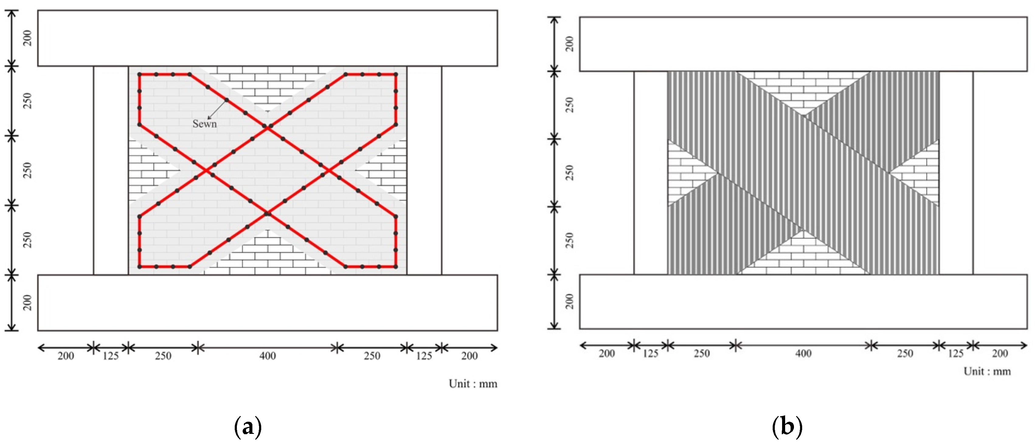
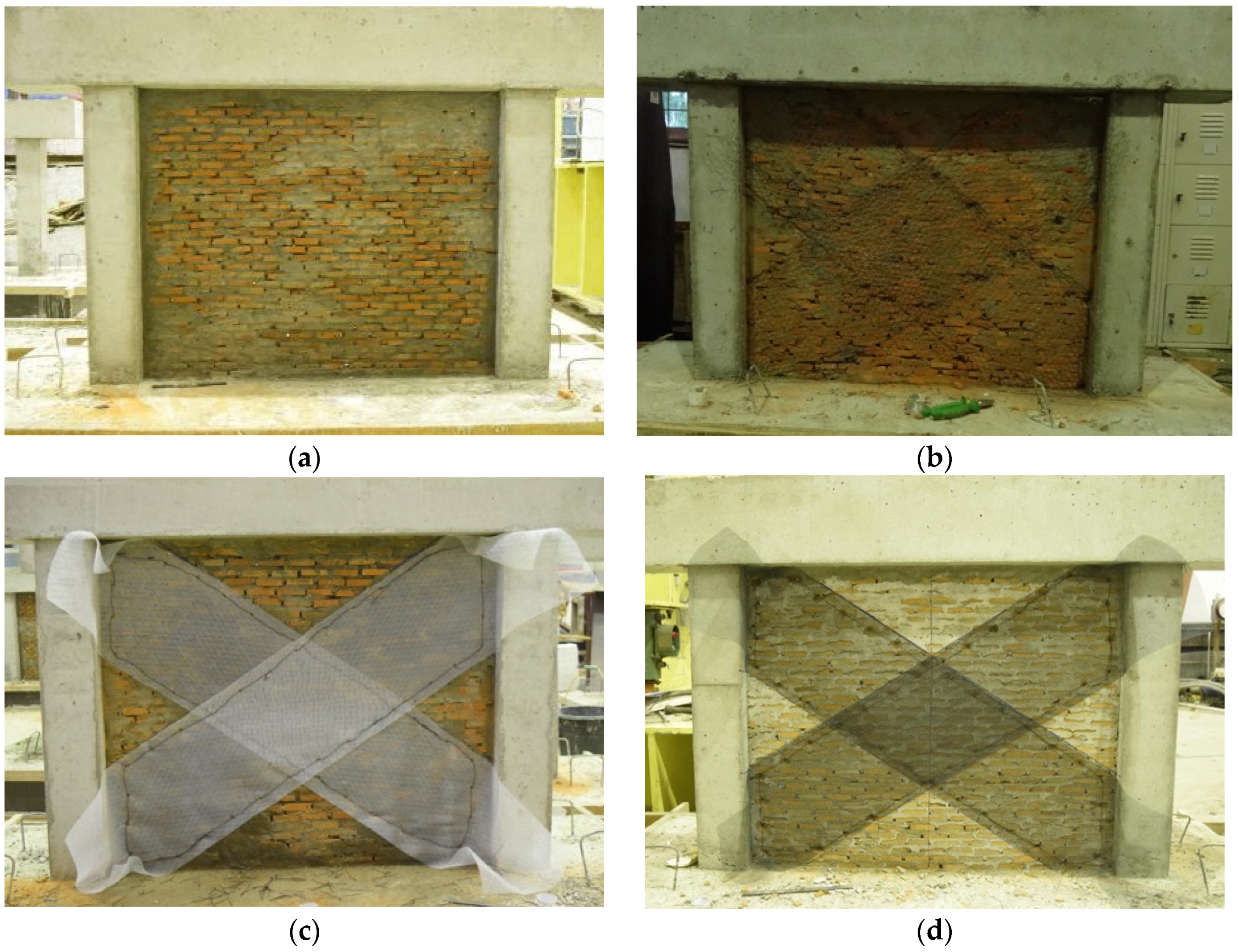
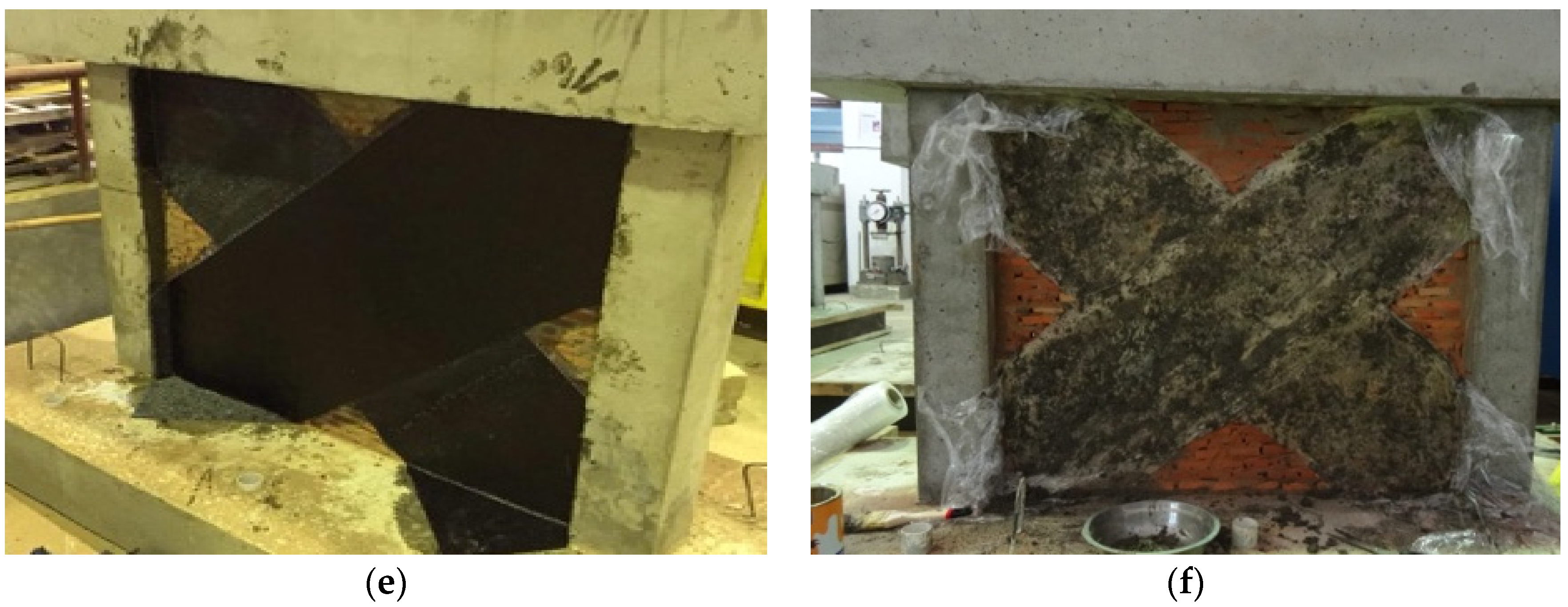
For masonry infill, the 1:4 reduced-scale burnt clay brick, with dimensions of 60 mm in length, 30 mm in width, and 13 mm in height and the mortar beds with a 1:0.5 ratio of cement:water, were used and applied. Six masonry-infilled RC frame specimens were prepared for this study, i.e., one constructed with a masonry infill without strengthening (IFSW) and five with strengthened masonry infills. The infills were then covered with 5 mm of mortar on both surfaces as plastering. The materials used for strengthening were textile plastic reinforcement mesh (IFSM–P), steel wire mesh (IFSM–S), chicken hexagonal wire mesh (IFSM–A), fiber-reinforced polymer (IFSM–FRP), and plastic stretch film (IFSM–PW). Figure 2 shows a sketch of the strengthening method of infills. The masonry infill was strengthened in a diagonal pattern on both sides of the surface of the infill. For the IFSM–P, IFSM–S, and IFSM–A, the strengthening materials were sewn using steel wire at each 12 cm distance in two diagonal directions on both sides of the brick masonry infill. The ends of the mesh were attached to the columns and beams of the RC frame using a chemical epoxy adhesive. Finally, plastered mortar layers were applied to the strengthened infills. For the IFSM–FRP specimen, the FRP sheet was glued to both sides of the masonry infill surfaces and attached to the columns and beams using epoxy resin. A skilled applicator was employed to install the FRP sheet properly. For the IFSM–PW specimen, three layers of plastic stretch film were applied. The plastic stretch film was glued using synthetic rubber adhesive. The specimens, after installation and the strengthening of the infill, can be seen in Figure 3.

2.2. Material Properties

The properties of the materials used to construct the specimens were defined according to standard material testing procedures. The compressive strength was 37.3 MPa for the concrete, 7.8 MPa for the brick masonry, 9.4 MPa for the brick unit, and 13.9 MPa for the bed joint mortar. The nominal tensile yields for the reinforcements of Ø4, Ø6, D10, and D13 were 390.2 MPa, 346.8 MPa, 449.5 MPa, and 443.5 MPa, respectively. Meanwhile, for ultimate strengths were 574.9 MPa, 446.3 MPa, 612.0 MPa, and 603.9 MPa for each of the reinforcements.

2.3. Experimental Setup and Testing Procedure

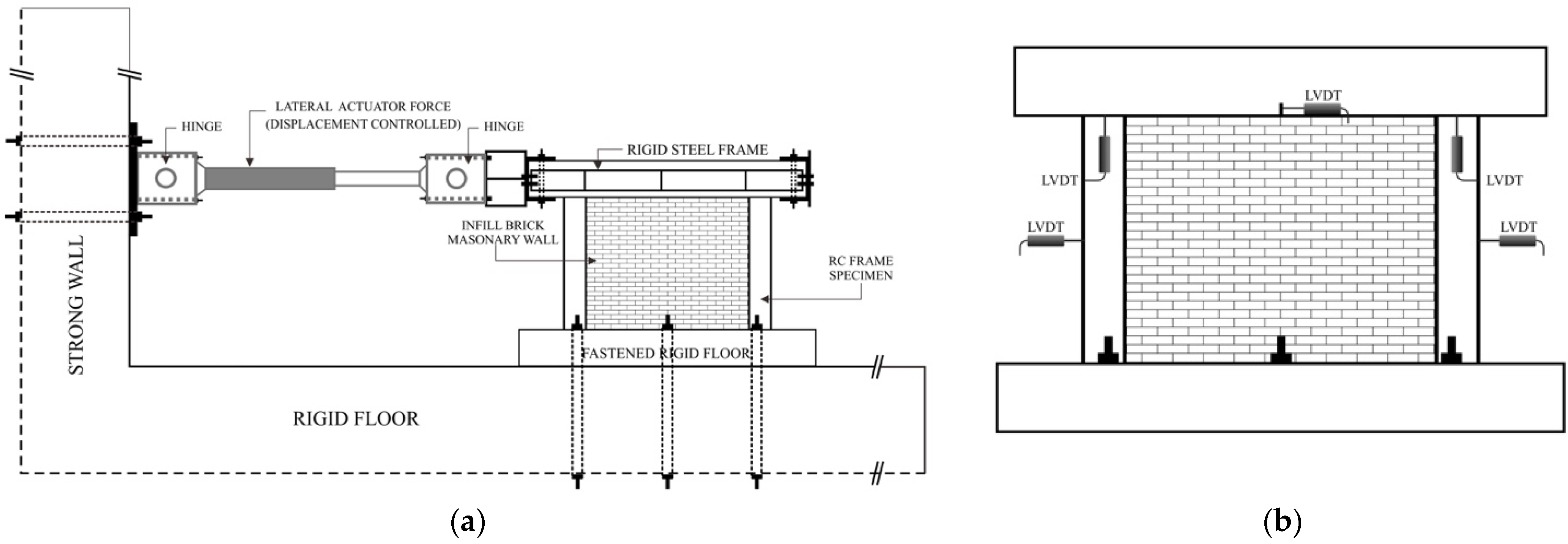
A schematic image of the experimental setup is shown in Figure 4a. A specimen was connected to the rigid floor through the lower beam. Six post–tensioning rods were used to fasten the lower beam to its rigid floor. The top beam was clamped using steel beams to prevent out–of–plane deformation of the specimen during loading. These steel beams were then connected to the double-action lateral actuator, which was mounted on the strong wall. We installed and placed several displacement transducers (LVDTs) to monitor and measure the deformation of the specimen. The positions of these LVDTs are shown in Figure 4b. One displacement transducer was placed in the middle of the top beam as a displacement control point during loading.
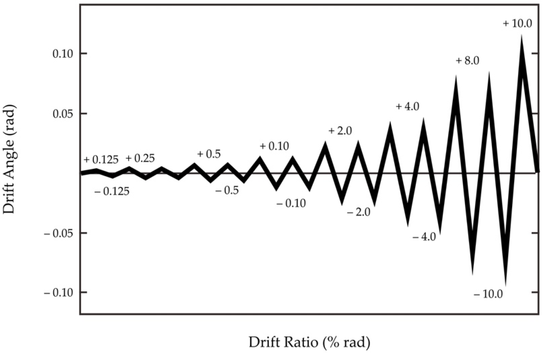
The lateral static reversed cyclic loading was directed on the top beam of the specimen by controlling the displacement with a speed of approximately 0.05 mm/s. The testing procedure follows the FEMA 461 standard [41]. The target of lateral movement (δ) for each cycle was defined according to the column’s drift ratio (R), where δ = R.H is the target lateral displacement and H is the height of the column. Figure 5 shows the complete cyclic loading, i.e., one cycle for R = 1/800, two cycles for R = 1/400, R = 1/200, R = 1/100, R = 1/50, R = 1/25, and R = 1/12.5, and finally by pushover for R = 1/10. For each cycle, the initial crack and its propagation were drawn on the surfaces of the specimens. Its drawing was observed to identify the failure mechanism of the specimens.

3. Test Results and Discussion

3.1. The Failure Mechanism of the Specimens

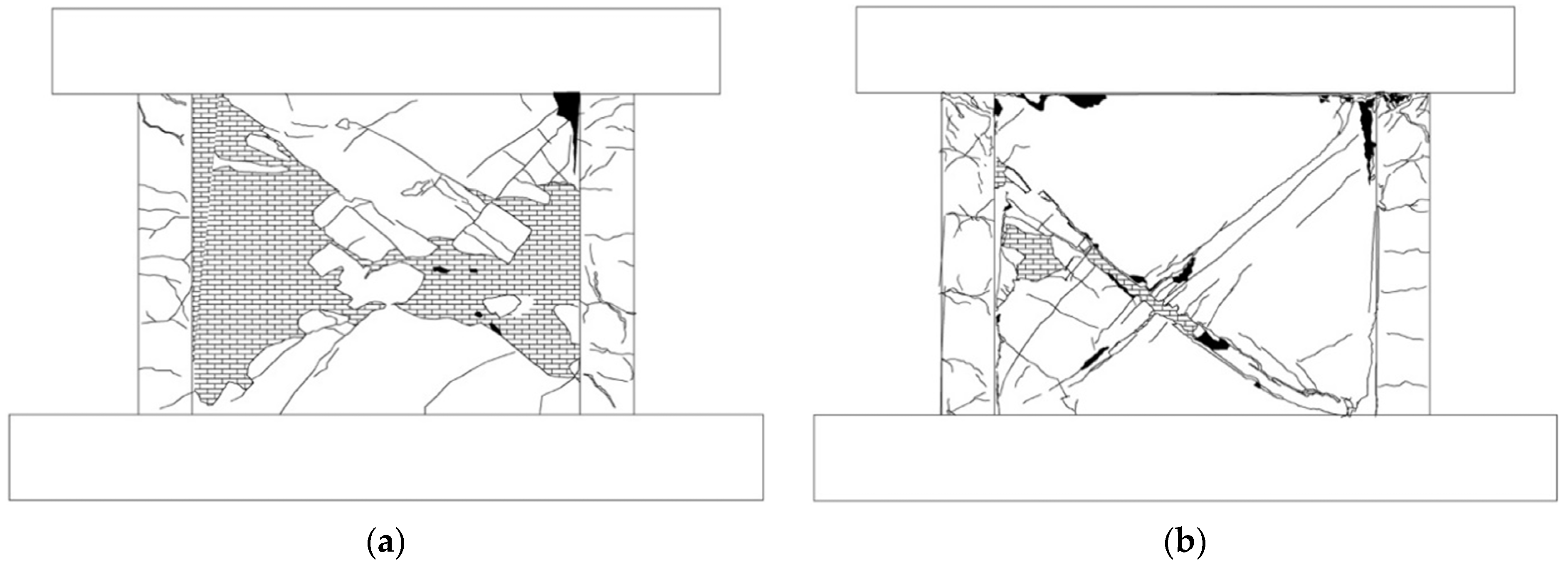
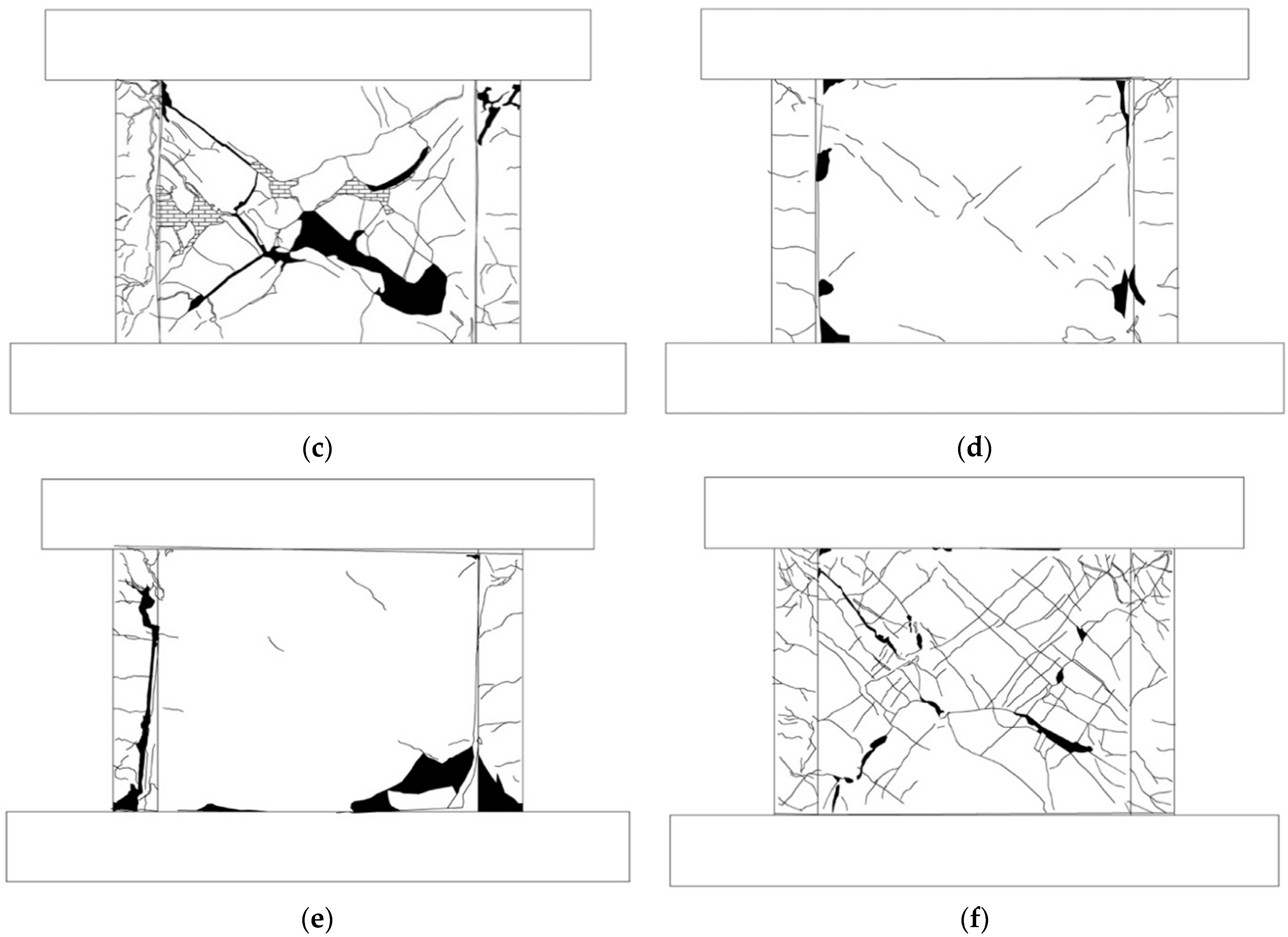
The crack patterns for all specimens are drawn in Figure 6. The first flexural crack on the column and initial shear crack on the infill was observed on the IFSW specimen during the drift ratio of R = 1/800, while the initial shear crack occurred at the end of the column when loading at a drift ratio of R = 1/100 and lateral deformation of about 6.43 mm. The infill suffered intensive cracking in both diagonal directions and failed in shear at the lateral deformation of 8.49 mm on the drift ratio of R = 1/50. At the lateral deformation of 57.20 mm and drift ratio of R = 1/12.5, the column also had a shear failure, and the infill partially collapsed. The drawing of the crack pattern of the IFSW specimen is shown in Figure 6a.
The initial flexural crack on the column appeared almost at the same time for the IFSM–A, IFSM–P, and IFSM–S specimens, i.e., at the drift ratio of R = 1/400. Further, the initial shear cracks on the columns of these specimens were at the drift ratios of R = 1/100, R = 1/200, and R = 200, i.e., at lateral deformations of 5.91 mm, 3.74 mm, and 7.72 mm, respectively. The infill of the IFSM–A and IFSM–P specimens initiated shear cracking at the drift ratio of R = 1/400 and the lateral deformation of 1.82 mm, while for the IFSM–S specimen, the drift ratio was at R = 1/100 and the lateral deformation was at 7.72 mm. The shear cracks on the infill and the end of columns were continuously escalated by increasing the lateral deformation. The infill of the IFSM–P specimen had a shear failure at the drift ratio of R = 1/25 and the lateral deformation of 26.38 mm before the shear failure on the column at the drift ratio of R = 1/12.5 and the lateral deformation of 57.39 mm. For the IFSM–A and IFSM–S specimens, the infill and the columns underwent shear failure at the drift ratio of R = 1/12.5 and the lateral deformation of 59.7 mm. The separation between columns and infills occurred in these specimens after the drift ratio of R = 1/12.5. On the contrary, the IFSM–P specimen did not experience a separation between the infill and its columns. The strengthening of the infill using plastic material on the IFSM–P made it more ductile than other materials.
Strengthening the infill of the IFSM–FRP specimen with the FRP sheet significantly increased the stiffness of the infill. Consequently, the infill stiffness became larger than the stiffness of the columns. As a result, the initial flexural crack appeared on the column at the beginning of the cyclic loading at R = 1/800. The initial shear crack on the infill started at the drift ratio of R = 1/50 and the lateral deformation of 14.82 mm. The column had already failed at a small lateral deformation of 2.01 mm. Since the strength of the FRP sheet material is stronger than the scaled-down 1:4 RC columns, the columns failed before the FRP sheet reached its maximum capacity. Therefore, no failure appeared on the FRP sheet, such as local debonding or tensile failure.
An interesting result was obtained after testing the IFSM–PW specimen. The initial flexural crack on the column and the initial shear crack on the infill also appeared at the beginning of the cyclic load R = 1/800 and the lateral deformation of 0.93 mm. The initial crack was detected on the bottom of the column at the drift ratio of R = 1/200 and the lateral deformation of 3.7 mm. Although the infill suffered intensive cracking in both diagonal directions, it showed excellent ductility until it failed at the drift ratio of R = 1/12.5. The columns also had a shear failure at the drift ratio of R = 1/12.5, i.e., at the lateral deformation of 60 mm. Both the columns and the infill had flexural deformation, and there was no separation between the columns and the infill. There was no significant decrease in the lateral strength of the specimen after the shear failure of the column and the infill.

3.2. Performance Evaluation

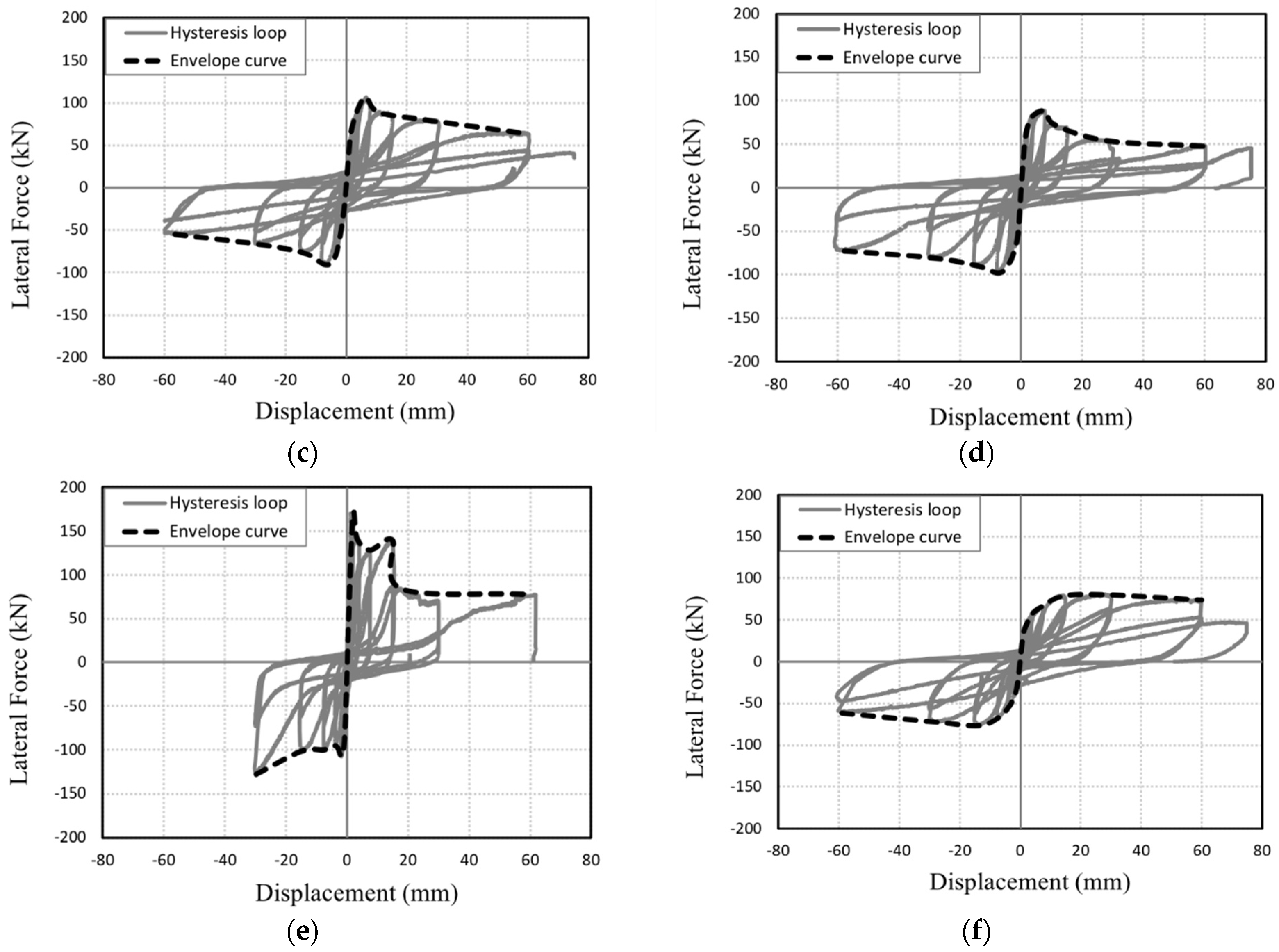
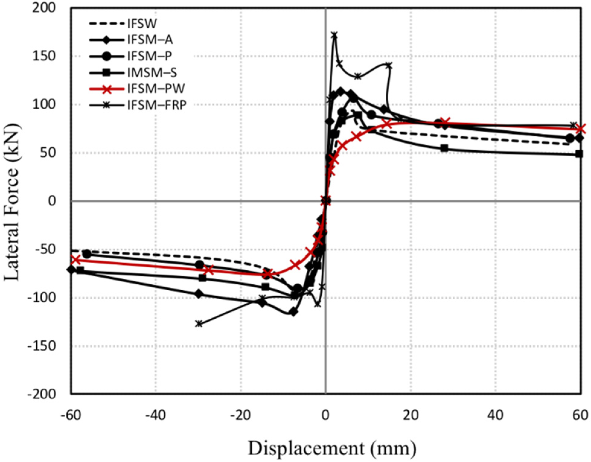
The performance of the specimens was defined according to the following parameters: lateral strength, deformation capacity, degradation of the stiffness, and dissipated energy against the lateral loading. Figure 7 shows the hysteresis loop displaying the lateral load and deformation relationships. The maximum lateral strength of the IFSW, IFSM–A, IFSM–P, IFSM–S, IFSM–FRP, and IFSM–PW specimens were 93.59 kN, 114.95 kN, 106.33 kN, 97.80 kN, 171.4 kN, and 80.61 kN, respectively. These maximum lateral strengths were recorded at lateral deformations of 6.43 mm, 7.68 mm, 6.54 mm, 7.29 mm, 2.01 mm, and 28.12 mm, respectively. Figure 8 shows the comparison of the skeleton curve for all specimens. These curves represent the peak lateral strength of each applied cyclic loading for the specimens. Compared to the IFSM specimen, the lateral strength of the IFSM–A, IFSM–P, and IFSM–S specimens increased by about 22.84%, 13.61%, and 5.28%, respectively. Strengthening the infill using FRP in the IFSM–FRP specimen significantly increased the infill stiffness, resulting in a punching load in the diagonal direction of the infill to the end of columns. Consequently, the lateral strength increased by about 83.13% compared to the IFSW specimen. The columns suffered large lateral and axial loading, causing specimen failure due to a shear crack on the end of the columns.

3.3. Deformation Capacity

The deformation capacity is defined as a deformation where post-peak lateral strength dropped to 80% of the peak strength [2]. The deformation capacity for all specimens is tabulated in Table 1. Note that the deformation capacity of IFSM–PW was set to be 60 mm since the dropped strength after peak strength was not seen clearly. The deformation capacity is related to the ductility of the specimen. Increasing the deformation capacity value means increasing the specimen’s ductility. The experimental results show that strengthening in the IFSM–PW specimen had the best performance in ductility.

3.4. Stiffness Degradation

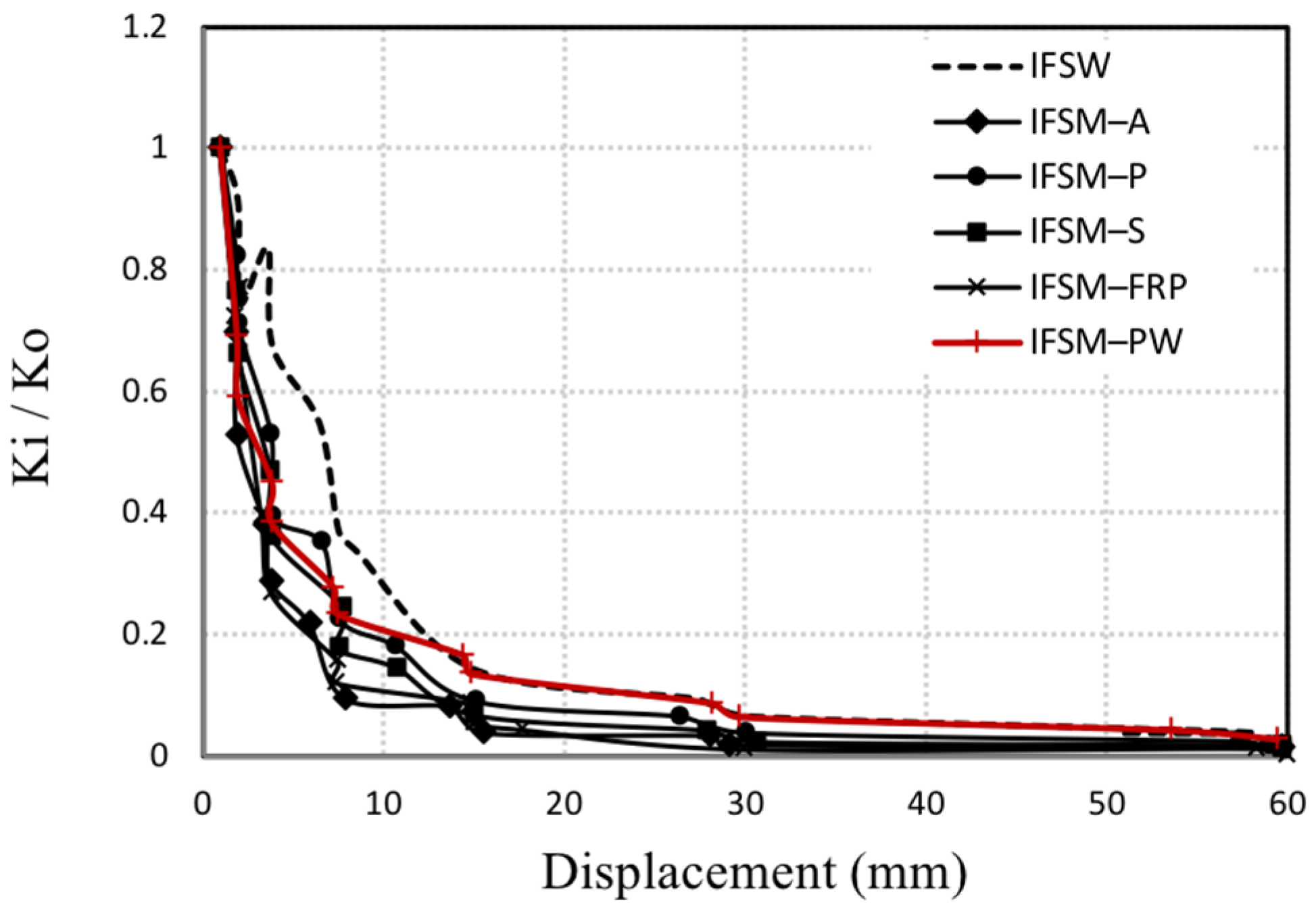
The secant stiffness of the specimens is drawn in Figure 9. Compared to the IFSW specimen, except for IFSM–PW specimens, strengthening the infill significantly increased the stiffness of the specimens. Due to the high tensile properties of the strengthening materials, the IFSM–A and IFSM–FRP specimens experienced great increases in stiffness. Figure 10 shows the stiffness degradation of the specimens, which represents the deterioration of the mechanical properties of the specimens under reversed cyclic loading. Its stiffness degradation was drawn from the ratio Ki/Ko, where Ki is the secant stiffness at the i cycle, and Ko is the initial secant stiffness. The secant stiffness of the IFSW, IFSM–A, IFSM–P, IFSM–S, IFSM–FRP, and IFSM–PW specimens was degraded at about 54.7%, 21.7%, 35.1%, 24.3%, 76.9%, and 8.6% after yield, respectively. These results suggest that the strengthening material used in the IFSM–PW specimen resulted in better ductile performance than other strengthening materials.

3.5. Energy Dissipation

Energy dissipation represents the ability of the RC frame specimen to absorb energy subjected to reversed cyclic lateral loading and is determined as the hysteresis loop area. The cumulative dissipated energy for specimens is provided in Figure 11. These results exhibit good performance among the specimens using strengthened infill, which means strengthened infill improves the energy dissipation of the infilled frame structure and indicates an increased capacity to resist the lateral load. An interesting result was obtained in the IFSM–PW specimen, where the energy dissipation increased after yielding. This revealed that the specimen was highly ductile and could resist lateral loads under large deformations.

4. Conclusions

This paper reports the experimental study of six RC frame masonry infilled specimens. The specimens included one without a strengthened infill and five with strengthened infills. The main findings can be summarized as follows:
  • Strengthening the infill successfully improved the specimens’ lateral strength, secant stiffness, deformation capacity, and energy dissipation.
  • Although the lateral of the IFSM–PW specimen was slightly increased, the lateral strength was maintained during plastic deformation. The plastic stretch film as a material for strengthening the infill made the infill more ductile compared to the infill without strengthening.
  • Unlike the IFSM–PW specimen, other specimens showed a significant increase in their secant stiffness, although it suddenly dropped after yielding.
  • The deformation capacity of the specimens with strengthened infills was increased. Due to high stiffness after strengthening using FRP on the infill of the IFSM–FRP specimen, the deformation capacity was only slightly increased.
  • Strengthening the infill improved the energy dissipation of the specimens. The strengthening in the IFSM–PW specimen resulted in the best performance in energy dissipation.
  • It can be concluded that strengthening using the plastic stretch film material is low cost and is feasible for application even by unskilled local laborers.

Author Contributions

Conceptualization, M. (Maidiawati) and J.T.; methodology, M. (Maidiawati), J.T. and Y.H.; formal analysis, M. (Maidiawati) and J.T.; investigation, M. (Maidiawati), J.T. and Y.H.; resources, M. (Maidiawati) and J.T.; data curation, M. (Maidiawati), J.T., F.M.N., Y.H. and M. (Masrilayanti); writing—original draft preparation, M. (Maidiawati); writing—review and editing, M. (Maidiawati), J.T., F.M.N., Y.H. and M. (Masrilayanti); visualization, M. (Maidiawati); supervision, M. (Maidiawati), J.T., F.M.N. and M. (Masrilayanti); project administration, M. (Maidiawati), J.T. and Y.H.; funding acquisition, M. (Maidiawati) and J.T. All authors have read and agreed to the published version of the manuscript.

Funding

The Ministry of Research and Technology/National Research and Innovation Agency of the Republic of Indonesia has funded this publication under the Decentralization Research Grant with the contract number 008/27.O10.5/PN/VI/2022.

Data Availability Statement

Not applicable.

Acknowledgments

The authors sincerely acknowledge the staff of the Structure and Construction Material Laboratory, Syiah Kuala University, for providing the facilities for structural testing.

Conflicts of Interest

The authors declare no potential conflict of interest with respect to the research, authorship, or publication of this article.

References

  1. Maidiawati; Sanada, Y. Investigation and analysis of buildings damaged during the September 2007 Sumatra, Indonesia Earthquakes. J. Asian Archit. Build. Eng. 2008, 7, 371–378. [Google Scholar] [CrossRef]
  2. Maidiawati; Sanada, Y.; Konishi, D.; Tanjung, J. Seismic performance of nonstructural brick walls used in Indonesian R/C Buildings. J. Asian Archit. Build. Eng. 2011, 10, 203–210. [Google Scholar] [CrossRef]
  3. Haach, V.G.; Vasconcelos, G.; Lourenco, P.B. Experimental analysis of reinforced concrete block masonry walls subjected to in-plane cyclic loading. J. Struct. Eng. 2010, 136, 452–462. [Google Scholar] [CrossRef]
  4. Cavaleri, L.; Trapani, F.D. Cyclic response of masonry infilled RC frames: Experimental results and simplified modeling. Soil Dyn. Earthq. Eng. 2014, 65, 224–242. [Google Scholar] [CrossRef]
  5. Tarque, N.; Candido, L.; Spacone, E. Masonry infilled frame structures: State-of-the-art review of numerical modelling. J. Earthq. Struct. 2015, 8, 733–759. [Google Scholar]
  6. Li, S.; Shan, S.; Zhai, C.; Xie, L. Experimental and numerical study on progressive collapse process of RC frames with full-height infill walls. Eng. Fail. Anal. 2016, 59, 57–68. [Google Scholar] [CrossRef]
  7. Tanjung, J.; Maidiawati; Nugroho, F. Experimental investigation of the seismic performance of the R/C frames with reinforced masonry infills. AIP Conf. Proc. 2017, 1892, 020009. [Google Scholar]
  8. Dautaj, A.D.; Kadiri, Q.; Kabashi, N. Experimental study on the contribution of masonry infill in the behavior of RC frame under seismic loading. J. Eng. Struct. 2018, 165, 27–37. [Google Scholar] [CrossRef]
  9. Dautaj, A.D.; Muriqi, A.; Cene, K.; Burbuqe, S. Shear resistance of masonry panel in infilled RC frames. Int. J. Adv. Struct. Eng. 2019, 11, 165–177. [Google Scholar] [CrossRef]
  10. Tanjung, J.; Maidiawati; Alfajri, A. Effect of brick masonry infills to seismic capacity of Indonesia multi-story RC building. Int. J. GEOMATE 2019, 16, 42–48. [Google Scholar] [CrossRef]
  11. Maidiawati; Tanjung, J.; Sanada, Y.; Nugroho, F.; Wardi, S. Seismic analysis of damaged buildings based on post-earthquake investigation of the 2018 Palu earthquake. Int. J. GEOMATE 2020, 18, 116–122. [Google Scholar] [CrossRef]
  12. Maidiawati; Tanjung, J. The seismic responses of RC frames infilled with full and partial masonry walls under cyclic lateral load. IOP Conf. Ser. Earth Environ. Sci. 2020, 708, 012079. [Google Scholar] [CrossRef]
  13. Cheng, S.; Zhu, Y.; Zhang, W. Seismic performance of RC frames strengthened by RC infill walls. Adv. Struct. Eng. 2021, 24, 2267–2281. [Google Scholar] [CrossRef]
  14. Wang, F.; Zhao, K.; Zhang, J.; Yan, K. Influence of different types of infill walls on the hysteretic performance of reinforced concrete frames. Buildings 2021, 11, 310. [Google Scholar] [CrossRef]
  15. Hashemi, A.; Mosalam, K.M. Shake-table experiment on reinforced concrete structure containing masonry infill wall. Earthquake Engng Struct. Dyn. 2006, 35, 1827–1852. [Google Scholar] [CrossRef]
  16. Lourenco, P.B.; Leite, J.M.; Pereira, M.F.P.; Costa, A.C.; Candeias, P.X.; Mendes, N. Shaking table testing for masonry infill walls: Unreinforced versus reinforced solutions. Earthquake Eng. Struct. Dyn. 2016, 45, 2241–2260. [Google Scholar]
  17. Climent, A.B.; Marquez, A.R.; Pujol, S. Seismic strengthening of low-rise reinforced concrete frame structures with masonry infill walls: Shaking-table test. Eng. Struct. 2018, 165, 142–151. [Google Scholar] [CrossRef]
  18. Maidiawati; Sanada, Y. R/C frame–infill interaction model and its application to Indonesian buildings. Earthquake Eng. Struct. Dyn. 2017, 46, 221–241. [Google Scholar] [CrossRef]
  19. Holmes, M. Steel frames with brickwork and concrete infilling. Proc. Inst. Civ. Eng. 1961, 19, 473–478. [Google Scholar] [CrossRef]
  20. Smith, B.S. Methods for predicting the lateral stiffness and strength of multi-storey infilled frames. Build. Sci. 1967, 2, 247–257. [Google Scholar] [CrossRef]
  21. Smith, B.S.; Carter, C. A method of analysis for infilled frames. Proc. Inst. Civ. Eng. 1969, 44, 31–48. [Google Scholar]
  22. Mainstone, R.J. On the stiffness and strength of infilled frames. Proc. Inst. Civ. Eng. 1971, 49, 57–90. [Google Scholar]
  23. Leuchars, J.M.; Scrivener, J.C. Masonry infill panels subjected to cyclic in-plane loading. Bull. N. Zld. Natl. Soc. Earthq. Eng. 1976, 9, 122–131. [Google Scholar] [CrossRef]
  24. Paulay, T.; Priestley, M.J.N. Seismic Design of Reinforced Concrete and Masonry Buildings; John Wiley & Sons: New York, NY, USA, 1992. [Google Scholar]
  25. Noh, N.M.; Liberatore, L.; Mollaioli, F.; Tesfamariam, S. Modelling of masonry infilled frames subjected to cyclic load: State of the art review and modelling with OpenSees. Eng. Struct. 2017, 150, 599–621. [Google Scholar]
  26. Pan, X.; Yan, J.; Wang, Z.; Zou, C. Numerical modeling and seismic evaluation of masonry-infilled reinforced concrete frames retrofitted with carbon fiber-reinforced polymer wraps. Adv. Struct. Eng. 2018, 21, 1526–1541. [Google Scholar] [CrossRef]
  27. Asteris, P.G. Lateral stiffness of brick masonry infilled plane frames. ASCE J. Struct. Eng. 2003, 129, 1071–1079. [Google Scholar] [CrossRef] [Green Version]
  28. Asteris, P.G. Finite Element Micro-Modeling of infilled frames. Elect. J. Struct. Eng. 2008, 8, 1–11. [Google Scholar]
  29. Asteris, P.G.; Cotsovos, D.M.; Chrysostomou, C.Z.; Mohebkhah, A.; Al-Chaar, G.K. Mathematical micromodeling of infilled frames: State of the art. J. Eng. Struct. 2013, 56, 1905–1921. [Google Scholar] [CrossRef]
  30. Mohyeddin, A.; Goldsworthy, H.M.; Gad, E.F. Sensitivity analysis of nonlinear behavior of infill-frames under in-plane and out-of-plane loading. Adv. Struct. Eng. 2013, 16, 1729–1747. [Google Scholar] [CrossRef]
  31. Vicente, R.S.; Rodrigues, H.; Varum, H.; Costa, A.; Silva, J.A.R.M. Performance of masonry enclosure walls: Lessons learned from recent earthquakes. Earthq. Eng. Eng. Vib. 2012, 11, 23–34. [Google Scholar] [CrossRef]
  32. Porto, F.; Guidi, G.; Verlato, N.; Modena, C. Effectiveness of plasters and textile reinforced mortars for strengthening clay masonry infill walls subjected to combined in-plane/out-of-plane actions. Mauerwerk 2015, 19, 334–354. [Google Scholar]
  33. Koutas, L.; Triantafillou, T.C.; Bousias, S.N. Analytical modeling of masonry-infilled rc frames retrofitted with textile-reinforced mortar. J. Compos. Constr. 2015, 19, 1–14. [Google Scholar] [CrossRef]
  34. Akhoundi, F.; Vasconcelos, G.; Lourenco, P. In-plane behavior of infills using glass fiber shear connectors in textile reinforced mortar (TRM) technique. Int. J. Struct. Glass Adv. Mater. Res. 2018, 2, 1–14. [Google Scholar] [CrossRef]
  35. Padalu, P.K.V.R.; Singh, Y.; Das, S. Cyclic two-way out-of-plane testing of unreinforced masonry walls retrofitted using composite materials. Constr. Build. Mater. 2020, 238, 117784. [Google Scholar] [CrossRef]
  36. Altin, S.; Anil, O.; Kara, M.E.; Kopraman, Y. Comparison of seismic performance of RC frames strengthened with four different techniques. Adv. Struct. Eng. 2012, 15, 343–357. [Google Scholar] [CrossRef]
  37. Leeanansaksiri, A.; Panyakapo, P.; Ruangrassamee, A. Seismic capacity of masonry infilled RC frame strengthening with expanded metal ferrocement. Eng. Struct. 2018, 159, 110–127. [Google Scholar] [CrossRef]
  38. Coccia, S.; Carlo, F.D.; Imperatore, S. Masonry walls retrofitted with vertical FRP rebars. Buildings 2020, 10, 72. [Google Scholar] [CrossRef]
  39. Tanjung, J.; Ismail, F.A.; Maidiawati; Putra, R. A Simple method for strengthening the brick masonry infilled in the reinforced concrete frame structure. Int. J. GEOMATE 2020, 18, 118–123. [Google Scholar] [CrossRef]
  40. Furtado, A.; Rodrigues, H.; Arede, A.; Varum, H. Experimental test on strengthening strategies for masonry infillwall: A literature review. Constr. Build. Mater. 2020, 262, 120520. [Google Scholar] [CrossRef]
  41. FEMA 461. Interim Testing Protocols for Determining the Seismic Performance Characteristic of Structural and Nonstructural Component; Applied Technology Council: Redwood City, CA, USA, 2007; pp. 21–25. [Google Scholar]
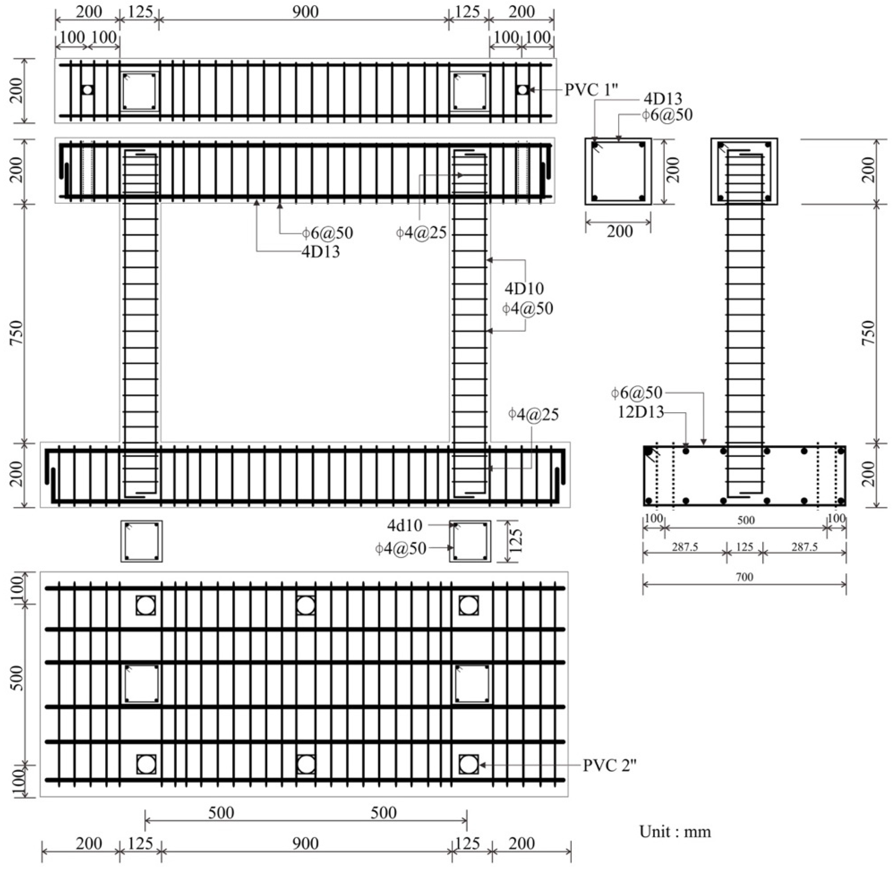
Figure 1. Geometric and reinforcement detail of the RC frame specimen.
Buildings 12 01496 g001
Figure 2. Sketch of strengthening method of infills. (a) Strengthening the infill with textile plastic reinforcement mesh/steel wire mesh/chicken hexagonal wire mesh. (b) Strengthening the infill with fiber-reinforced polymer/plastic stretch film.
Buildings 12 01496 g002
Figure 3. The RC frame with masonry infill specimens: (a) IFSW specimen, (b) IFSM–A specimen, (c) IFSM–P specimen, (d) IFSM–S specimen, (e) IFSM–FRP specimen, and (f) IFSM–PW specimen.
Buildings 12 01496 g003aBuildings 12 01496 g003b
Figure 4. Schematic view of the test setup: (a) actuator set up and (b) transducer set up.
Buildings 12 01496 g004
Figure 5. Loading history.
Buildings 12 01496 g005
Figure 6. The cracking patterns of specimens at the drift angle R = 1/12.5: (a) IFSW specimen, (b) IFSM–A specimen, (c) IFSM–P specimen, (d) IFSM–S specimen, (e) IFSM–FRP specimen, and (f) IFSM–PW specimen.
Buildings 12 01496 g006aBuildings 12 01496 g006b
Figure 7. Lateral force-displacement relationships for all specimens: (a) IFSW specimen, (b) IFSM–A specimen, (c) IFSM–P specimen, (d) IFSM–S specimen, (e) IFSM–FRM specimen, and (f) IFSM–PW specimen.
Buildings 12 01496 g007aBuildings 12 01496 g007b
Figure 8. Skeleton curves of specimens.
Buildings 12 01496 g008
Figure 9. Secant stiffness of specimens.
Buildings 12 01496 g009
Figure 10. Stiffness degradation of specimens.
Buildings 12 01496 g010
Figure 11. Cumulative energy dissipation of specimens.
Buildings 12 01496 g011
Table 1. The peak strengths and deformation capacities of specimens.
Peak StrengthDeformation Capacity
Name of SpecimensVmax (kN)Displacement (mm)Lateral Strength (kN)Displacement (mm)
IFSW93.596.4375.88.49
IFSM-P106.336.5488.9810.62
IFSM-S97.807.2980.4629.01
IFSM-A114.957.6896.8229.92
IFSM-FRP171.402.01128.517.47
IFSM-PW80.6128.1274.3060.0
Publisher’s Note: MDPI stays neutral with regard to jurisdictional claims in published maps and institutional affiliations.