Article

Shear Behavior of Steel-Fiber-Reinforced Recycled Aggregate Concrete Deep Beams

Department of Civil and Environmental Engineering, UAE University, Al Ain P.O. Box 15551, United Arab Emirates
*
Author to whom correspondence should be addressed.
Buildings 2021, 11(9), 423; https://doi.org/10.3390/buildings11090423
Submission received: 26 August 2021 / Revised: 17 September 2021 / Accepted: 19 September 2021 / Published: 21 September 2021
(This article belongs to the Section Building Structures)

Abstract

:
Results of an experimental investigation aimed at studying the effect of steel fibers on the shear behavior of concrete deep beams made with a 100% recycled concrete aggregate (RCA) are presented in this paper. The study comprised testing of seven concrete deep beam specimens with a shear span-to-depth ratio (a/h) of 1.6. Two beams were made of natural aggregates (NAs) without steel fibers, two beams were made of a 100% RCA without steel fibers, and three beams were made of RCA-based concrete with steel fibers at volume fractions (vf) of 1, 2, and 3%. Two of the beams without steel fibers included a minimum shear reinforcement. Test results showed that the beam with a 100% RCA without steel fibers exhibited a lower post-cracking stiffness, reduced shear cracking load, and lower shear capacity than those of the NA-based control beam. The detrimental effect of the RCA on the shear response was less pronounced in the presence of the minimum shear reinforcement. The addition of steel fibers significantly improved the shear response of the RCA-based beams. The post-cracking stiffness of the RCA-based concrete beams with steel fibers coincided with that of a similar beam without fibers containing the minimum shear reinforcement. The use of steel fibers in RCA beams at vf of 1 and 2% restored 80 and 90% of the shear capacity, respectively, of a similar beam with the minimum shear reinforcement. The response of the RCA specimen with vf of 3% outperformed that of the NA-based control beam with the minimum shear reinforcement, indicating that steel fibers can be used in RCA deep beams as a substitution to the minimum shear reinforcement. The shear capacities obtained from the tests were compared with predictions of published analytical models.

1. Introduction

Construction and demolition waste (CDW) resulting from the demolition of concrete structures that reach the end of their service life has a detrimental impact on the environment [1]. Partial or full replacement of natural aggregates (NAs) with recycled concrete aggregates (RCAs) in concrete construction would reduce the environmental impact associated with the storage of CDW, consumption of natural resources, intake of energy, and stress on landfills. Concrete mixtures made with RCAs, generally, possess inferior mechanical properties relative to those of NAs [2,3,4]. Nevertheless, the effect of RCA replacement on the shear response of large-scale reinforced concrete (RC) beams is uncertain, since some researchers report an inferior shear behavior for RCA-based beams relative to that of NA-based counterparts [5,6,7,8,9], while others reported an insignificant variation in the shear response of NA- and RCA-based beams [10,11,12,13].
Arezoumandi et al. [5] reported a 12% reduction in the shear strength of beams with a shear span-to-effective depth ratio (a/d) of 3 and a 100% RCA replacement percentage compared to that of their NA-based counterparts. No difference was observed in the crack morphology, crack progression, and deflection response of NA- and RCA-based concrete beams. Rahal and Alrefaei [6] reported shear strength reductions in the range of 13 to 18% for RC beams with a/d of 3.4, with RCA replacement percentages in the range of 10 to 100%. In another study by the same authors [7], average reductions of 5 and 9% in the shear strength of RC beams with a/d of 3 were reported at RCA replacement percentages of 20 and 100%, respectively. A shear tension mode of failure was observed in all beams. The beams with a 100% RCA exhibited higher deflections than those of the NA beams at service and ultimate loads. This behavior was not evident for the beams with a 20% RCA replacement percentage. Wardeh and Ghorbel [8] reported that the shear strength of RC beams with a 100% RCA and a/d of 3 was 23% lower than that of their NA counterparts, while for those with a/d of 1.5 the reduction was more than 10%, noting that the full shear capacity of the NA-based beams with a/d = 1.5 was not reached due to the limited capacity of the loading actuator used in the test. Beams with a/d of 1.5 tended to exhibit a shear compression failure mode whereas a diagonal tension mode of failure was recorded for the beams with a/d of 3. The RCA-based beams showed flatter slopes in the post-cracking phase compared with those of the NA-based counterparts. The reduction in stiffness of the RCA beams was attributed to the reduced elastic modulus and tensile strength of the RCA-based concrete mixtures. Al Mahmoud et al. [9] reported a shear strength reduction of 11% due to full replacement of NA with RCA in RC beams with a/d of 2.6. The stiffness of the RCA-based beams was, however, comparable to that of the NA-based beams, and no change was reported in the failure mode.
In contrast, Gonzalez-Fonteboa and Martinez-Abella [10] reported no significant difference between the shear strength of NA-based concrete beams with a/d of 3 and that of similar beams made with a 50% RCA replacement percentage. Nevertheless, premature cracking and notable splitting cracks along the tension reinforcement were observed in RCA-based beams. Fathifazl et al. [11] reported no major differences between the failure mode, cracking pattern, and shear performance of RCA- and NA-based beams with different a/d ratios of 1.5, 2.0, 2.7, and 4.0, and various RCA replacement percentages of 0, 64, and 74%. Similarly, Khergamwala [12] reported comparable shear behavior for NA- and RCA-based concrete beams with 25 and 50% RCA replacement percentages irrespective of the a/d value that was in the range of 1.5 to 3. Short beams with a/d < 2.5 failed in a shear compression mode of failure, whereases slender beams with a/d ≥ 2.5 failed in a diagonal tension mode of failure. Ignjatović et al. [13] reported that the shear behavior of RCA-based beams with a/d of 4.2 with 50 and 100% replacement percentages was very similar to that of their NA counterparts. The difference between the service load deflection of the beams with and without RCAs was within 10%. The shear failure modes of RCA beams did not differ from that of their NA counterparts.
The aim toward wider use of RCAs in construction to promote the concept of sustainability and circular economy led researchers to investigate different methods to improve the performance of RCA-based concrete [14]. The inclusion of steel fibers in RCA-based concrete reduces the development of microcracks and improves different tensile properties of concrete mixtures [15,16,17]. Previous studies provided interesting findings on the shear behavior of steel-fiber-reinforced NA-based slender concrete beams [18,19,20,21]. Dinh et al. [18] reported a significant increase of 160% in the shear strength of RC beams with a/d of 3.5 due to the addition of steel fibers at vf of 0.75. Further increase in the steel fiber volume fraction to 1 and 1.5% resulted in a marginal additional improvement in the shear capacity. The length and type of the steel fibers had an insignificant effect on the shear response at vf ≤ 1%. In contrast, at vf of 1.5%, beams with the longer steel fibers of 610 mm exhibited a higher shear strength than those with fibers at a length of 381 mm. Sahoo and Sharma [19] concluded that the addition of steel fibers in RC beams with a/d of 3.45 at vf of 0.75, 1, and 1.25% increased the normalized shear strength by 5, 6, and 28%, respectively, compared to that of a control specimen without steel fibers. A steel fiber volume fraction of 0.75% was sufficient to achieve a shear strength equal to or higher than that of the beam with traditional steel stirrups. Amin and Foster [20] concluded that the addition of steel fibers in RC beams with a/d of 2.8 at vf of 0.5 and 1% increased the shear strength by 42 and 127%, respectively, compared to that of a similar beam without steel fibers. Beams with steel fibers exhibited a smaller crack width than that of the control beam without fibers. The number of shear cracks increased with an increase in the fiber volume fraction. The use of steel fibers at a high dosage (vf = 2%) resulted in a significant shear strength gain of 155% at a/d of 2.8 [21].
Steel fibers have a potential to improve the shear response of RC deep beams, noting that beams with a shear span-to-depth ratio (a/h) ≤ 2 are classified as deep beams [22]. The addition of steel fibers at vf of 1.5% in RC deep beams with a/d of 2 and a concrete cylinder compressive strength (f′c) of 37 MPa resulted in a shear strength gain of 12% whereas similar beams with f′c = 19 MPa experienced a shear strength gain of 54% [23]. In another study by Kang et al. [24], it was concluded that the addition of steel fibers to RC deep beams with a/d of 2 at vf of 0.5 and 0.75% resulted in shear strength gains of 16 and 18%, respectively. An improvement in the beams’ stiffness was also observed due to the addition of steel fibers [24]. The use of hybrid steel fibers (i.e., a combination of steel fibers with different shapes and geometry) can effectively bridge shear cracks in RC deep beams at both the micro- and macro-scale levels, thus improving the shear strength and deformation capacity [25]. The shear capacity of a concrete deep beam with a/d of 0.9 with a hybrid vf of 2% (1.5% long fibers and 0.5% short fibers) was two times that of a similar beam without fibers [25]. The performance of a deep beam with hybrid steel fibers without internal shear reinforcement outperformed that of a similar beam with internal shear reinforcement [25]. Recently, Garcia et al. [26] reported a shear strength gain of approximately 17% for a deep beam with a/h of 0.5 due to the inclusion of steel fibers at vf of 1%. Beams with a/h to 0.8 and 1 exhibited an average shear strength gain of 15%. Do-Dai et al. [27] reported up to a 55% increase in the shear strength of RC beams with a/h of 1.6 due to the use of steel fibers with vf in the range of 0.4 to 0.85%. Beams with steel fibers were stiffer than the control beam. The use of steel fibers also reduced the shear crack width by up to 11 times.
To date, little effort has been devoted to investigating the shear behavior of RCA-based concrete beams containing steel fibers, despite their ability to bridge cracks and improve the post-cracking tensile resistance of concrete. Chaboki et al. [28] investigated the effect of the addition of steel fibers at vf of 1 and 2% to improve the shear strength of slender beams with a/h of 2.5 made with 50 and 100% RCA. The inclusion of steel fibers enhanced the shear behavior of RCA-based concrete beams. In the absence of stirrups, the addition of steel fibers resulted in a significant increase in the shear capacity. Nevertheless, the shear strength gain was less pronounced for beams with traditional transverse reinforcement.
To the best of the knowledge of the authors, no information is available in the literature on the shear behavior of steel-fiber-reinforced RCA-based concrete deep beams (i.e., beams with a/h ≤ 2). They are commonly used as transfer girders in high-rise buildings and are vulnerable to fail in shear before reaching their flexural capacity. Further research is required to better understand the shear behavior of steel-fiber-reinforced RCA deep beams and advocate for a wider use of RCAs in structural applications. The present work aims to fill this gap by providing unique experimental evidence on the shear behavior of concrete deep beams made of a 100% RCA and different steel fiber volume fractions. Results of RCA-based concrete deep beams are compared to those of conventional deep beam specimens made of NA with and without stirrups. The accuracy and validity of published analytical models to predict the shear capacity of the tested beams were examined by comparing their predictions with the shear capacities obtained from the experiment.

2. Research Objectives

The widespread use of RCA in the construction industry is hindered by the lack of knowledge and contradicting information published in the literature on the structural behavior of RCA-based concrete members. The inclusion of steel fibers in RCA-based concrete structures would improve the structural performance, which would advocate for a wider acceptance of RCA for structural use, thus, supporting the concept of circular economy and sustainability. This research aims to investigate the shear behavior of steel-fiber-reinforced RCA-based concrete deep beams, commonly used as transfer girders in high-rise buildings and other important structural applications. Locally abundant desert dune sand is used in this work as fine aggregates to emphasize the contribution toward sustainable construction. The main objectives of the study are:
  • Investigate the effect of using a 100% RCA on the shear behavior of concrete deep beams with and without traditional shear reinforcement.
  • Examine the effectiveness of using steel fibers at different volume fractions to improve the shear behavior of RCA-based concrete deep beams.
  • Investigate the potential use of steel fibers as a substitution to traditional shear reinforcement in RCA-based concrete deep beams.
  • Examine the accuracy and validity of published analytical models to predict the shear capacity of the tested beams.

3. Experimental Program
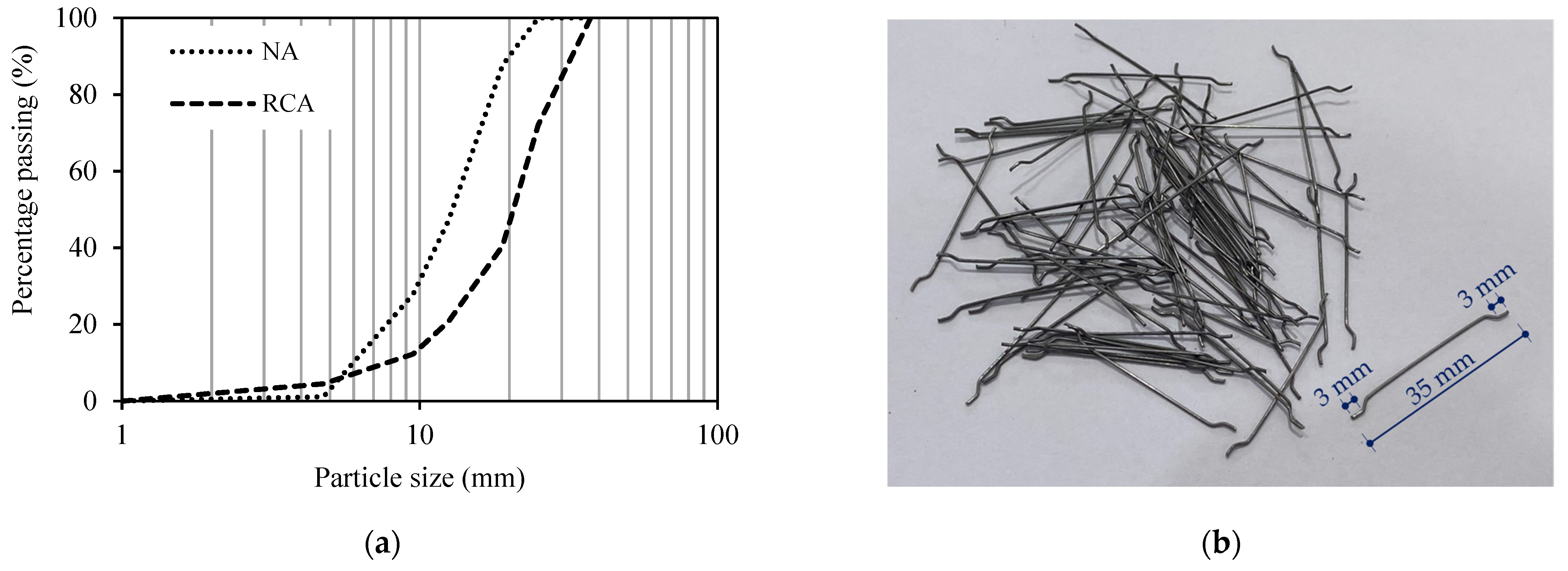
The study comprised testing of seven RC deep beam specimens with a/h of 1.6. Details of the experimental program are presented in the following subsections.

3.1. Materials

The concrete constituent materials included ASTM type I ordinary Portland cement (OPC), coarse aggregates, fine aggregates, and tap water. Coarse aggregates were in the form of NAs and RCAs. The NAs were crushed dolomitic limestone with a nominal maximum particle size (NMS) of 19 mm, obtained from the Emirate of Ras Al Khaimah, United Arab Emirates (UAE). The RCAs were collected from a local concrete recycling plant, located in the Emirate of Abu Dhabi, with an NMS of 25 mm. The concrete recycling plant crushes old concrete structures with an unknown compressive strength. The fine aggregates were locally abundant desert dune sand with a bulk density of 1663 kg/m3, surface area of 116.8 cm2/g, specific gravity of 2.77, and fineness modulus of 1.45. Dune sand was used as a fine aggregate in all concrete mixtures to promote the concept of sustainable construction. The detailed physical properties of the NAs and RCAs are presented in Table 1. Compared to NAs, RCAs had lower bulk density, higher water absorption, higher LA abrasion mass loss, lower specific gravity, and higher fineness modulus. Properties of RCAs were within the acceptable limits except for the water absorption, which was higher [29,30,31,32,33]. The gradation curves of the coarse aggregates are shown in Figure 1a. The particle size distributions of coarse aggregate were within the upper- and lower-limit bounds of ASTM C33 [34].
The measured yield strength of the longitudinal reinforcing steel bars used in the beam specimens was 539 MPa, whereas the shear reinforcement had a measured yield strength of 505 MPa. The Young’s modulus of the reinforcing steel bars was 200 GPa. Dramix® 3D 65/35BG hooked-end steel fibers, supplied by Bekaert, Dubai, UAE, were used in the current study. They are low-carbon, cold-drawn round steel fibers with a tensile strength of 1345 N/mm2, Young’s modulus of 210 GPa, diameter (Df) of 0.55 mm, length (lf) of 35 mm, and an aspect ratio (lf/Df) of 65 [35]. Figure 1b shows a photograph of the steel fibers used in the present study. It should be noted that the manufacturer does not recommend a maximum dosage of steel fibers in concrete mixtures. Generally, the maximum dosage of steel fibers depends on the concrete composition, placing method, and type of application. In the present study, trial mixes were carried out prior to casting of the beams to ensure adequate workability of the concrete and a homogeneous distribution of the steel fibers within the concrete mixture. Segregation, bleeding, and agglomeration of steel fibers were not observed in any of the mixtures. Similarly, preliminary trial mixes and tests should be done in a practical setting to evaluate fresh and hardened properties of designed steel-fiber-reinforced concrete mixtures with different dosages of steel fibers before adopting a particular mix design in construction projects.

3.2. Mixture Proportioning

The concrete control mixture was prepared based on the concrete mix design procedure of ACI 211.1 [36] to develop a design compressive strength of f′c = 30 MPa. Table 2 presents the proportions of the concrete mixtures used in this study. The mixtures are labeled RX-SFY, where ‘X’ denotes the RCA replacement percentage and ‘Y’ refers to vf. The RCA replacement percentage is defined as the mass ratio of RCA relative to the coarse aggregates. For instance, R100-SF1 is the designation of the mixture made with a 100% RCA with the incorporation of steel fibers at vf of 1%. The total amount of coarse aggregates, cement, dune sand, and water were kept constant in all mixtures.

3.3. Specimens Preparation

Concrete mixture constituents were mixed in a laboratory mechanical mixer. The quantity of water needed in the mix design (Table 2) was based on using the aggregates in a saturated surface dry (SSD) condition. To account for the water absorption capacity of the NAs and RCAs, the dry aggregates were first placed into the mixer. The amount of water needed for the aggregates to reach the SSD condition was then added and mixed with the coarse aggregates for 3 min. The steel fibers, if present, were then mixed with the coarse aggregates to ensure a uniform dispersion of fibers. The cement and dune sand were then added at a later stage and mixed for another 2 min. Finally, the amount of free water, per the mix design, was gradually added and mixed with other components for an additional 2 min. This mixing procedure ensured a homogenous and uniform mixture. Wooden molds were used in the fabrication of the deep beam specimens. The reinforcement cages were placed in their designated positions. The concrete mixture was placed, compacted by a vibrator, and then leveled. The concrete surface was smoothened using a finishing trowel. Segregation, bleeding, and agglomeration of steel fibers were not observed during casting. The deep beam specimens were cured using wetted burlaps for seven consecutive days, then air-cured for a minimum of 28 days. Concrete cylinders and cubes were also sampled for characterization of concrete mechanical properties, compacted on a vibration table, demolded after 24 h, and then water-cured for 28 days. Figure 2 shows photographs of steel-fiber-reinforced concrete mixtures during placement and after being trowel-finished.

3.4. Properties of Concrete Mixtures

The fresh concrete slump was measured directly after mixing, following the procedure of ASTM C143 [37]. The compressive strength characteristics of the concrete used in this study were determined from three 150 mm cubes and three cylinders 150 mm × 300 mm (diameter and height), tested in accordance with BS 12390-3 [38] and ASTM C39 [39], respectively. The modulus of elasticity was obtained in accordance with ASTM C469 [40]. The splitting tensile strength was obtained from three cylindrical specimens with dimensions of 150 mm × 300 mm (diameter and height) and tested as per ASTM C496 [41]. The average values along with the corresponding standard deviation of the 28-day concrete cylinder compressive strength, f′c, cube compressive strength, fcu, modulus of elasticity, Ec, and splitting tensile strength, fsp, are reported in Table 3.

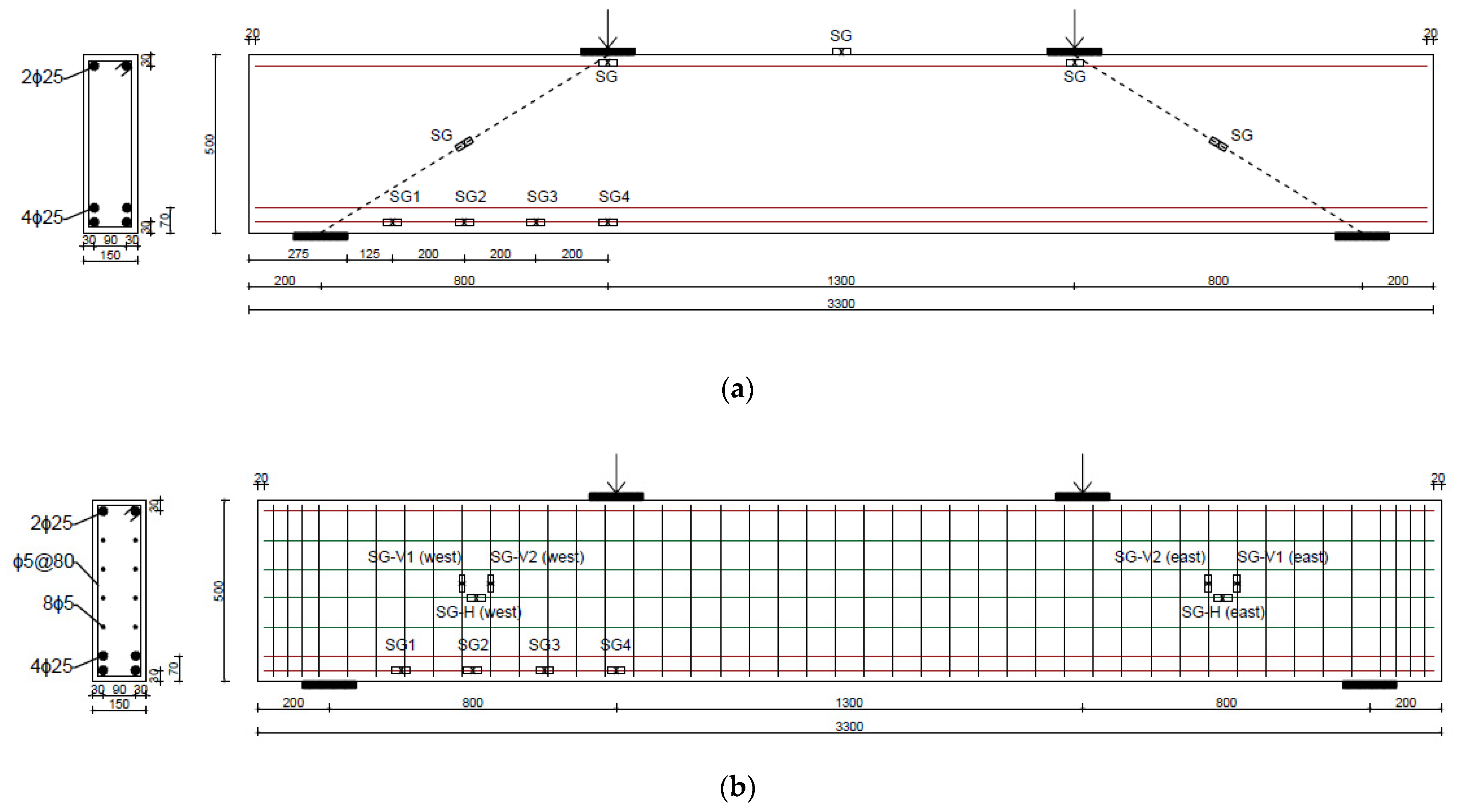
3.5. Deep Beam Test Specimens

Seven RC deep beam specimens were tested under four-point loading. The test matrix is given in Table 4. The deep beams are designated using the notation BRX-SFY, where ‘X’ is the RCA replacement percentage and ‘Y’ is vf. The notation BRX-SFY-S designates a beam specimen with traditional shear reinforcement. Two beams were made of NA without steel fibers, two beams were made of a 100% RCA without steel fibers, and three beams were made of a 100% RCA and steel fibers at vf of 1, 2, and 3%. Two of the beams without steel fibers included a minimum amount of traditional shear reinforcement. Concrete dimensions and details of reinforcement of beam specimens with and without traditional shear reinforcement are shown in Figure 3a,b, respectively. All beams had a rectangular cross-section of 150 mm in width and 500 mm in depth. The length of the beam was 3300 mm with an effective span of 2900 mm. A distance of 200 mm from each side of the beam was left free to provide a sufficient development length for the longitudinal steel reinforcement. The a/h was 1.6, resulting in a shear span of 800 mm and a constant moment region of 1300 mm. The beams were reinforced with four no. 25 (25 mm in diameter) longitudinal steel reinforcing bars at the tension side and two no. 25 (25 mm in diameter) bars at the compression side. The concrete cover to the center of the steel reinforcement was 50 mm, rendering an effective depth of d = 450 mm. This arrangement of steel reinforcement was decided to ensure that the beams would fail by shear. The traditional shear reinforcement, when employed, was detailed in accordance with the minimum shear reinforcement provisions of ACI 318-14 [22] for deep beams, resulting in an 80 mm stirrup spacing of 5 mm diameter placed in the horizontal and transverse directions. Steel plates (150 mm × 150 mm × 20 mm) were placed at the load and support points.

3.6. Test Setup

Two actuators, 1300 mm apart, were used to apply the load to the top surface of the beam. The applied loads of the actuators were recorded by two load cells. Initially, the tests were conducted under a load control rate of 0.5 kN/s. At approximately 80% of the expected shear capacity, the loading scheme was switched to a displacement control at a rate of 0.6 mm/min for safety considerations. Three linear variable differential transducers (LVDTs) were placed below the beam, one at midspan and one at each support, to measure the net midspan deflection. The net midspan deflection was calculated as the difference between the measured deflection at the midspan and the average of the deflection at the supports. Four strain gauges (SGs), 5 mm long each, were bonded to the bottom layer of the longitudinal steel reinforcing bars within the shear span at a spacing of 200 mm to measure the tensile steel strain. Three SGs, 5 mm long each, were installed on one horizontal and two vertical stirrups located at the center of each shear span with shear reinforcement. Figure 3b shows the location of the strain gauges attached to steel reinforcing bars and stirrups. Five SGs, 60 mm long each, were bonded to the concrete surface to measure the concrete strains. The concrete SGs were placed longitudinally at the midspan and under the loading points and diagonally at the middle of each shear span. Figure 3a shows the location of the concrete SGs attached to the concrete surface. Concrete SGs were also attached to the concrete surface of the beams with stirrups, but are not shown in Figure 3b for clarity. The load cells, LVDTs, and SGs were connected to a data acquisition system. Before conducting the tests, the front surfaces of the beams were painted white to facilitate tracing of cracks. Cracks developed during testing were marked, and the corresponding load values were recorded.

4. Experimental Results and Discussion

The shear behavior of the tested deep beams is evaluated in this section based on the shear load–deflection response, shear cracking load, shear capacity, crack pattern, failure mode, and strain measurements.

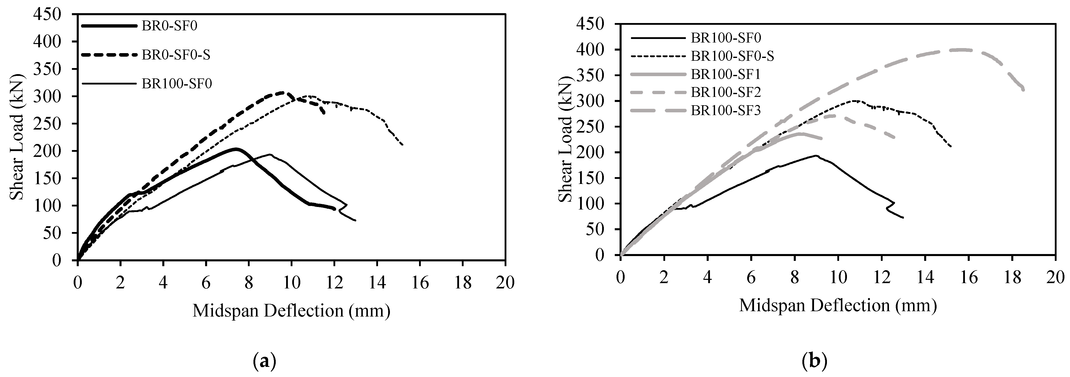
4.1. Deflection Response

The shear load–deflection responses of the beams without steel fibers are depicted in Figure 4a. Specimens BR0-SF0 and BR100-SF0, without traditional shear reinforcement, exhibited a load decay at the onset of shear cracking followed by a significant change in slope of the deflection response. Conversely, specimens BR0-SF0-S and BR100-SF0-S, with traditional shear reinforcement, exhibited a quasilinear response till the peak load. The RCA-based specimens BR100-SF0 and BR100-SF0-S exhibited a lower stiffness than those of their NA-based counterparts BR0-SF0 and BR0-SF0-S, respectively. Yet, the reduction in the beam stiffness was less pronounced in the presence of traditional shear reinforcement. For instance, at 150 kN, the midspan deflection of specimen BR100-SF0 was 6 mm, whereas specimen BR0-SF0 exhibited a midspan deflection of 4 mm only. At the same load of 150 kN, specimens BR100-SF0-S and BR0-SF0-S exhibited midspan deflections of 4 and 3.5 mm, respectively. The midspan deflection values at shear cracking, Δcr, and that recorded at shear capacity, Δmax, are reported in Table 5. The RCA-based specimens reached their shear capacity at midspan deflections higher than those of their NA-based counterparts. The increase in the deflection of RCA-based beams can be attributed to the lower Young’s modulus of the RCA-based concrete mixtures and the porosity of the RCA used [16,17].
Figure 4b shows the shear load–deflection response of the RCA-based concrete beams with and without steel fibers. It is evident that the addition of steel fibers improved the shear response of the RCA-based beams. Such specimens did not exhibit a load decay or a significant change in slope at the onset of shear cracking. The midspan deflection values at shear cracking loads of the RCA-based specimens with steel fibers were higher than those of the beams without fibers and further increased by increasing the fiber volume fraction (Table 5). Increasing the steel fiber volume fraction in RCA-based beams with steel fibers increased the deflection at the shear capacity. The RCA-based beams with steel fibers exhibited a quasilinear deflection response similar to that of the specimens with traditional shear reinforcement. This behavior can be attributed to the effect of steel fibers on restricting crack growth in the post-cracking phase. Additionally, the stiffness of specimens BR100-SF1 and BR100-SF2 with vf of 1 and 2%, respectively, coincided with that of BR100-SF0-S, with traditional shear reinforcement, while that of specimen BR100-SF3 with vf of 3% was superior to that of BR100-SF0-S. In fact, the stiffness of BR100-SF3 coincided with that of BR0-SF0-S, with NAs and traditional shear reinforcement. The improved stiffness of the RCA-based specimens with steel fibers could be ascribed to the bridging effect of the fibers, which acted as a crack arrestor during the post-cracking stage.

4.2. Shear Cracking Load and Shear Capacity

The shear cracking load, Vcr, and shear capacity, Vmax, along with the corresponding deflections, are reported in Table 5. The table also compares the ratio of Vcr/Vmax and the gain in the shear capacity of the tested specimens caused by the addition of steel fibers at different volume fractions. The shear cracking load, Vcr, is defined as the load at which the first visible shear crack appears in the shear span. The shear cracking and capacity of the RCA-based specimen BR100-SF0 were 25 and 5% lower than those of BR0-SF0, respectively. The impact of using a 100% RCA rather than NAs was less significant in the presence of traditional shear reinforcement since only 12 and 2% reductions in the shear cracking load and capacity were recorded, respectively. Specimens with RCAs also exhibited lower Vcr/Vmax ratios than those of their counterparts with NAs. The reductions in the shear cracking load and capacity of the RCA-based specimens can be attributed to the inferior mechanical properties of the RCA-based mixture.
Table 5 also shows that the inclusion of steel fibers in the RCA-based beams resulted in a remarkable increase in their shear cracking load to a level even higher than that of the NA-based specimen BR0-SF0-S with traditional shear reinforcement. The RCA-based specimens with steel fibers also exhibited higher Vcr/Vmax values than that of the beam specimens with traditional shear reinforcement, owing to the ability of steel fibers to delay the initiation of shear cracks. The shear capacity of the RCA-based beams with steel fibers was also improved. Specimens BR100-SF1, BR100-SF2, and BR100-SF3 exhibited shear capacity gains of 22, 40, and 107%, respectively, relative to that of BR100-SF0 without fibers. The increase in shear capacity can be attributed to the improved post-cracking resistance of the steel-fiber-reinforced specimens and their ability to restrict crack propagation and growth. The shear capacities of BR100-SF1 and BR100-SF2 were approximately 80 and 90% of that of specimen BR100-SF0-S with traditional shear reinforcement, respectively. Specimen BR100-SF3 with vf of 3% exhibited a shear capacity even higher than those of BR0-SF0-S and BR100-SF0-S, which had traditional shear reinforcement. This finding indicates that the use of steel fibers in RCA-based beams has great potential to substitute the minimum traditional shear reinforcement specified by ACI 318-14 [22].

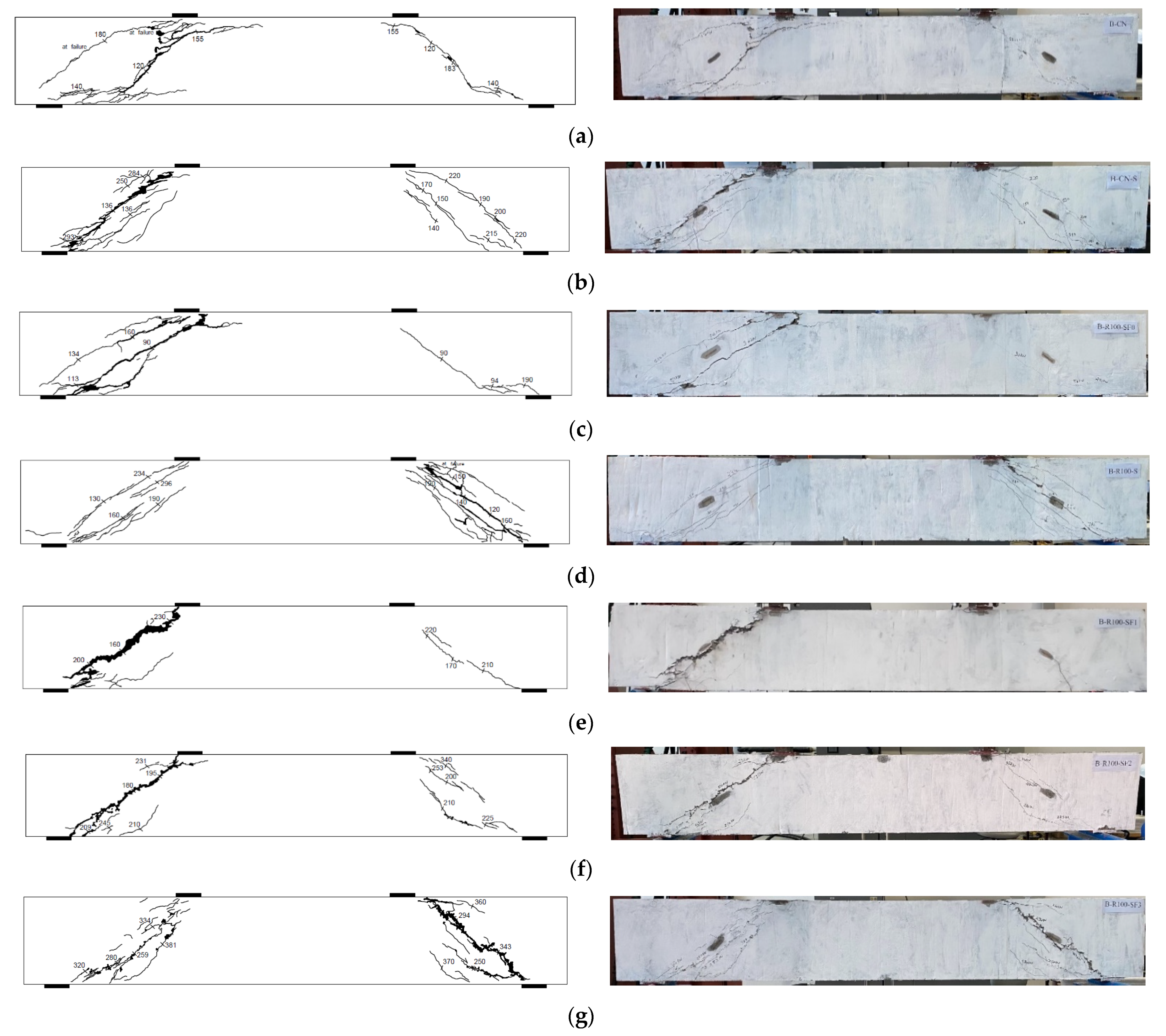
4.3. Crack Pattern and Failure Mode
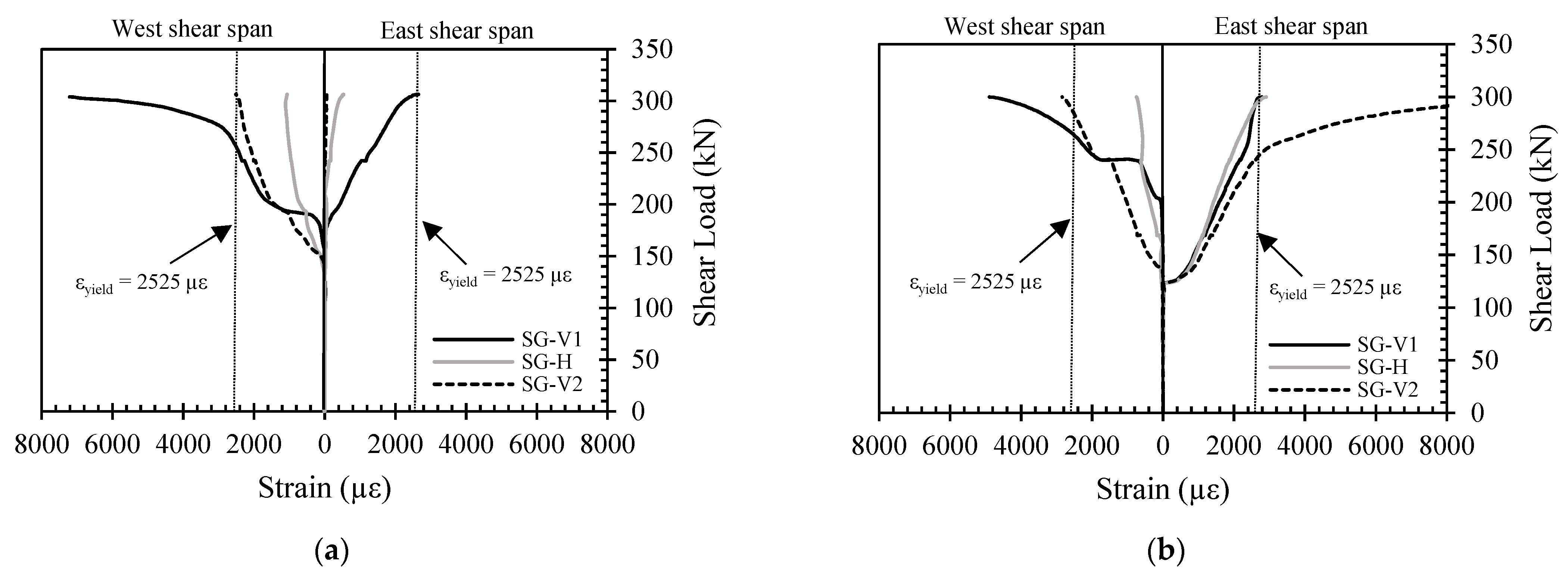
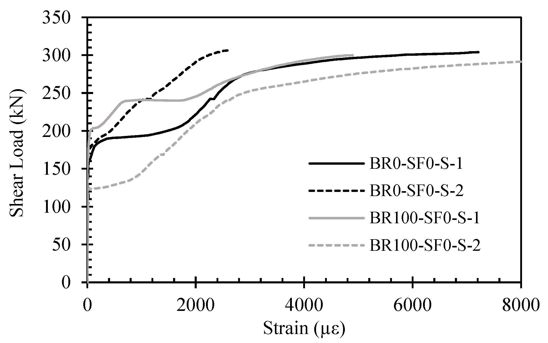
Figure 5 shows the crack patterns observed at failure. All beams failed in shear as planned in the design. Initially, the beams experienced inclined shear cracks at the mid-height of the shear span. As the load progressed, the cracks propagated toward the load and support points. Specimens BR0-SF0 and BR100-SF0, which had neither traditional shear reinforcement nor steel fibers, exhibited splitting cracks in the shear span parallel to the longitudinal steel reinforcing bars. At the onset of failure, specimen BR0-SF0 exhibited an additional diagonal crack in the west shear span accompanied by crushing of concrete at the top part of the diagonal concrete strut in the west shear span (Figure 5a). Specimen BR100-SF0 also exhibited a diagonal crack parallel to the initially formed major shear crack during testing, then eventually in a shear compression mode of failure due to crushing of the concrete above the head of the major diagonal crack developed in the shear span. Spalling of concrete was also observed at the level of the longitudinal tensile reinforcement at crack intersection points (Figure 5c). The two specimens, BR0-SF0-S and BR100-SF-S, with traditional shear reinforcement but without steel fibers exhibited a band of multiple cracks within the shear span, then eventually failed due to crushing of the concrete along the diagonal concrete strut as shown in Figure 5b,d, respectively.
The steel fibers in RCA-based beams played a role similar to that of the traditional shear reinforcement, since they delayed initiation and propagation of diagonal shear cracks and prevented formation of premature splitting cracks along the tensile reinforcement. Following crack initiation, the steel fibers controlled widening of cracks, delayed their propagation, and helped to maintain the integrity of the beams until failure occurred. Specimen BR100-SF1 with vf of 1% exhibited one major crack in the shear span in addition to a very fine crack that was observed at the onset of failure (Figure 5e). Specimen BR100-SF1 failed due to fracture of concrete across the major diagonal crack developed in the shear span accompanied by crushing of the top and bottom parts of the diagonal strut. Specimens BR100-SF2 and BR100-SF3 with vf of 2 and 3%, respectively, failed due to crushing of the diagonal concrete strut in the shear span (Figure 5f,g).

4.4. Sirrup Strains

The relationship between the shear load and stirrup strains is illustrated in Figure 6. The maximum measured strains in the shear reinforcement are plotted in Figure 7. The stirrup strain profile can be divided into two or three phases depending on whether stirrups have yielded or not. The first phase represents the pre-cracking stage, while the second phase signifies the post-cracking stage, i.e., from shear crack initiation to stirrup yielding or beam failure. The third phase occurs only in the case of yielded stirrups, i.e., the post-yielding phase. From Figure 6, it can be noted that the shear reinforcement was not strained in the first stage. Meanwhile, in the second stage, the strain in the shear reinforcement increased almost linearly, although some load decays were observed in some cases, possibly due to the development of new shear cracks at the location of the SGs. The third phase, if it existed, exhibited a significant increase in the stirrup strain with an insignificant increase in load. From Figure 6a, it can be seen that two vertical stirrups, one at each shear span, in addition to a horizontal stirrup in the west shear span of specimen BR0-SF0-S, have yielded prior to failure. Figure 6b shows that all measured strains in the shear reinforcement of BR100-SF0-S, except one reading for the horizontal stirrups in the west shear span, reached the yield strain at the peak shear load. Figure 7 shows that the rate of increase in stirrup strain of specimens BR0-SF0-S and BR100-SF0-S was insignificantly different. Only one vertical stirrup in specimen BR0-SF0-S exhibited a lower rate of stirrup strain than that experienced by other stirrups. The variation in the rate of increase in stirrup strain may be ascribed to the location of SG with respect to the location of the shear cracks. Strain gauges that are intersected by major shear cracks are expected to exhibit higher strains than those away from the cracks. Strain measurements confirmed the yielding of shear reinforcement at different locations in specimens BR0-SF0-S and BR100-SF0-S prior to failure.

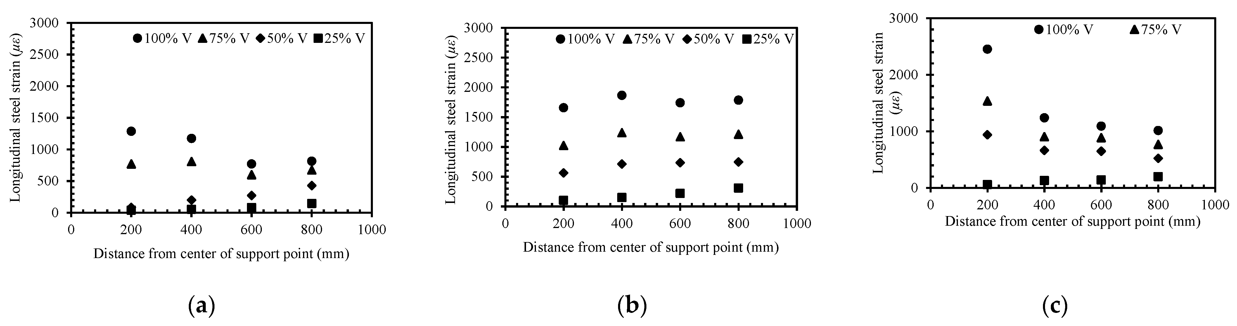
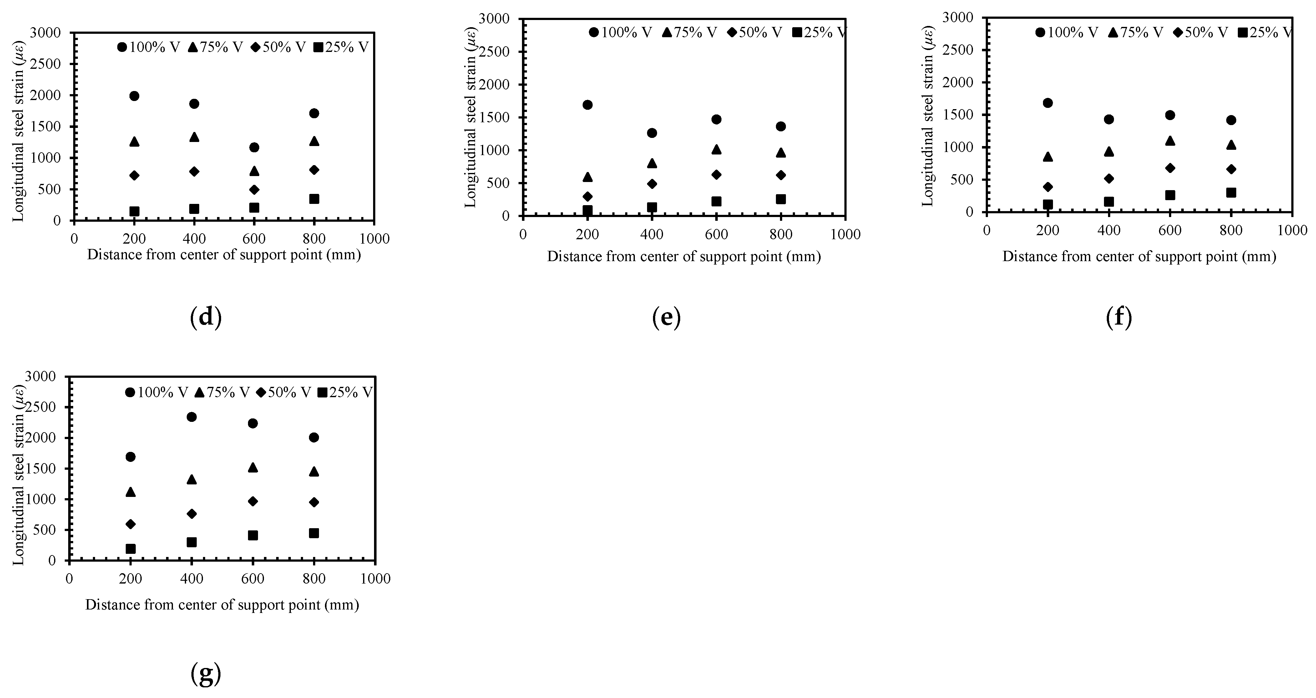
4.5. Tensile Steel Strains

The tensile steel strain profiles of the tested specimens at four different loading stages, 25, 50, 75, and 100% of the shear capacity, are shown in Figure 8, whereas the maximum measured tensile steel strains at the shear capacity are presented in Table 6. It is evident that the steel strains in all beams were less than the yield strain as planned in the design (εyield = 2695 µε). The steel strain values increased at all locations as the load increased. The specimens exhibited almost a uniform steel strain profile within the shear span which confirmed the occurrence of the deep beam action. Specimen BR100-SF0 (Figure 8c) showed a slightly different trend. It exhibited an almost uniform strain profile within the shear span until it reached approximately 50% of the shear capacity. At higher values of load, local spalling of concrete caused by the intersection of cracks at a distance of 200 mm from the support resulted in an increase in the steel strain at this location to a level higher than those recorded at other locations with the shear span. Additionally, in specimen BR100-SF0-S (Figure 8d), the strain did not increase at the same rate at 600 mm from the support after reaching 25% of the shear capacity, possibly due to the absence of major cracks that intersected the longitudinal reinforcement at this location.
The maximum measured tensile steel strain at the shear capacity reported in Table 6 was almost proportional to the load capacity of the tested specimens. Specimen BR100-SF0 was an exception since it exhibited the highest steel strain at the shear capacity, possibly due to the local spalling of concrete that occurred at the crack intersection located at a distance of 200 mm from the support, which left the steel exposed, and thus increased the steel strain values. It is worth noting that specimen BR100-SF3 exhibited the highest steel strain at the shear capacity among the steel-fiber-reinforced specimens and those with traditional shear reinforcement. This behavior can be attributed to the presence of steel fibers in the concrete mixture, which allowed the beam to sustain higher loads, and hence, higher tensile steel strains at shear capacity.

4.6. Concrete Strains

The maximum longitudinal and diagonal concrete strains measured at the shear capacity are reported in Table 6. It can be seen that the RCA-based control specimens BR100-SF0 and BR100-SF0-S exhibited higher maximum diagonal concrete strains compared to those of the NA-based control specimens BR0-SF0 and BR0-SF0-S, respectively, possibly because of the reduced Young’s modulus of the RCA-based concrete. This behavior was less evident for the longitudinal concrete strains of the counterpart specimens. The maximum concrete strains at the shear capacity of the specimens with traditional shear reinforcement were significantly different than those of their counterparts without shear reinforcement, except for the longitudinal concrete strain values of the counterpart specimens BR100-SF0 and BR100-SF0-S, which showed higher strains at the shear capacity in the presence of stirrups.
The steel-fiber-reinforced RCA specimens exhibited higher maximum longitudinal concrete strains at the shear capacity than those of the control RCA-based specimen BR100-Sf0. Their diagonal concrete strains at the shear capacity were higher than those of all other specimens. Specimen BR100-SF3 with vf of 3% exhibited the highest longitudinal and diagonal concrete strain values at the shear capacity. The higher concrete strain values exhibited by the steel-fiber-reinforced RCA specimens can be ascribed to the confinement effect provided by the steel fibers and their ability to increase the strain capacity of the diagonal strut.

5. Analytical Procedure

The nominal shear capacity of RC deep beams can be expressed by Equation (1), where Vc is the concrete contribution to the shear resistance including the dowel action and effect of steel fibers, and Vsh is the contribution of the internal shear reinforcement to the shear capacity. The concrete contribution to the shear capacity, Vc, including the influence of steel fibers and dowel action, is affected by mechanical properties of the concrete, fiber volume fraction (vf), flexural steel reinforcement ratio (ρ), and a/d. The contribution of the internal shear reinforcement, Vsh, is influenced by the type of steel, area of shear reinforcement bars, and number of shear reinforcing bars intersected by the critical shear crack.
Vn = Vc + Vsh
Narayanan and Darwish [42] proposed the empirical formula of Equation (2) for the average concrete shear stress at shear failure (i.e., ultimate shear stress), vu, which is defined by Vc/bd, where b is the beam width and d is the effective depth of the beam (i.e., distance between the compression face and centroid of the tension steel reinforcement). The magnitude of e in Equation (2) depends on a/d; e = 1 when a/d > 2.8 and e = 2.8(d/a) when a/d ≤ 2.8, whereas df is a bond factor that accounts for the bond characteristics of steel fibers and equals 0.5 for round fibers, 0.75 for crimped fibers, and 1 for indented fibers. The parameter τ is the average fiber matrix interfacial bond stress, 4.15 MPa.
vu = e [0.24fsp + 80ρ(d/a)] + 0.41τ (lf vf df/Df)
Ashour et al. [43] proposed Equation (3) to predict the ultimate shear stress of RC beams with a/d ≥ 2.5 and Equation (4) for beams with a/d < 2.5.
v u = [ 2.11 f c 3 + 7 ( l f v f   d f D f ) ]   [ ρ ( d / a ) ] 1 / 3 ;   for   a / d     2.5
v u = [ 2.11 f c 3 + 7 ( l f v f   d f D f ) ]   [ ρ ( d / a ) ] 1 / 3   [ 2.5 ( a / d ) ] + 0.41 τ ( l f v f   d f D f )   [ 2.5 ( a / d ) ] ;   for   a / d   <   2.5
Kwak et al. [44] proposed Equation (5) as a modified version of that developed earlier by Narayanan and Darwish [42] to predict the ultimate shear stress of RC beams. The factor k in Equation (5) depends on a/d; k = 1 for a/d > 3.4 and k = 3.4(d/a) for a/d ≤ 3.4.
vu = 3.7k(fsp)2/3[ρ(d/a)]1/3 + 0.8[0.41τ (lf vf df/Df)]
The contribution of the internal shear reinforcement to the shear capacity, Vsh, can be expressed by Equation (6), proposed by Kong et al. [45] and adopted by the CIRIA guide [46], where Cs is an empirical coefficient equal to 100 MPa for plain round bars and 225 MPa for deformed bars, h is the beam depth, and Ast is the area of an individual web steel bar, y is the depth of the intersection between the web steel bar and a potential critical shear crack measured from the compression face of the beam, and α is the angle of intersection between the web steel bar and the potential critical shear crack. The potential critical shear crack in RC deep beams is typically assumed to be developed in the direction of the natural load path, which is the line connecting the inner points of the load and support plates.
Vsh = Cs ∑[(Ast × y)/h] sin2α
The shear capacities predicted analytically are compared to those obtained from the tests in Table 7. The analytical approach of Narayanan and Darwish [42] provided reasonable predictions for the shear capacity of the tested beams, except for BR100-SF1 and BR100-SF2, where their shear capacities were overestimated by 17 and 26%, respectively. The ratio of predicted-to-measured shear capacity (Vn/Vmax) of the model by Narayanan and Darwish [42] was on average 1.07, with a corresponding standard deviation (Std Dev) of 0.11 and coefficient of variation (COV) of 11%.
The analytical approach by Ashour et al. [43] provided conservative predictions for the shear capacity of all of the tested beams, except BR100-SF2, where its shear capacity was overestimated by 14%. The deviation between predicted and experimental results was more significant for the beams without steel fibers. The model by Ashour et al. [43] computes the contribution of the plain concrete to the shear resistance as a function of the concrete compressive strength, f′c, rather than the splitting tensile strength, fsp. This fact may explain why the model by Ashour et al. [43] tended to provide conservative predictions for the shear capacity. The value of Vn/Vmax of the model by Ashour et al. [43] was on average 0.9 with a corresponding Std Dev of 0.14 and COV of 15%.
The model by Kwak et al. [44] overestimated the shear capacity of the majority of the tested beams. The value of Vn/Vmax of the model by Kwak et al. [44] was in the range of 0.95 to 1.27 with an average of 1.12, Std Dev of 0.13 and COV of 11%.
The difference between experimental results and those predicted by the models is considered within the typical margin of error considering the variability in shear test results. As such, it can be concluded that the three analytical models can provide reasonable predictions for the nominal shear capacity of the RC deep beams tested in the present study, noting that the model by Narayanan and Darwish [42] provided the most accurate prediction for the beams without steel fibers and that by Ashour et al. [43] provided the most accurate prediction for the beams with steel fibers.

6. Conclusions

This research examined the shear behavior of steel-fiber-reinforced RCA concrete deep beams. The effect of full replacement of NAs with RCAs on the shear response of the deep beam specimens with and without traditional shear reinforcement was elucidated (objective one). The effectiveness of using steel fibers at different volume fractions to improve the shear behavior of RCA-based concrete deep beams was revealed (objective two). The potential use of steel fibers as a substitution to traditional shear reinforcement in RCA-based concrete deep beams was investigated (objective three). A comparative analysis has been conducted to examine the accuracy and validity of three different analytical models published in the literature to predict the shear capacity of the tested beams (objective four). The main conclusions of the work are summarized hereafter:
  • Concrete deep beam specimens with a 100% RCA without steel fibers exhibited a lower stiffness, reduced shear cracking load, lower shear capacity, and higher midspan deflections than those of their NA-based counterparts. This is a new finding since no information is available in the literature on the shear behavior of RCA-based concrete deep beams. Nevertheless, this conclusion is in line with data published in the literature for slender beams [5,6,7,8,9], indicating the inferior structural shear performance for RCA-based concrete slender beams.
  • The impact of using a 100% RCA rather than NAs on the shear response was less significant in the presence of traditional shear reinforcement. The shear cracking load and shear capacity were reduced by 25 and 5% in the absence of traditional shear reinforcement due to the full replacement of NA by RCA. Nevertheless, only 12 and 2% reductions in the shear cracking load and shear capacity, respectively, were recorded in the presence of traditional shear reinforcement. The negligible shear strength reduction observed in the present study for RCA-based beams with internal shear reinforcement is consistent with that reported in the literature for beams with internal steel stirrups with a/h of 2.5 [28].
  • The inclusion of steel fibers in RCA-based deep beam specimens significantly improved their post-cracking stiffness. The stiffness of the RCA-based specimens with vf of 1 and 2% coincided with that of their RCA-based counterpart with traditional shear reinforcement. The inclusion of steel fibers at vf of 3% further improved the beam stiffness to a level even higher than that of its counterpart with traditional shear reinforcement. The improvement in the post-cracking stiffness of RCA-based beams due to the addition of steel fibers is a new finding, despite being consistent with other findings published in the literature for NA-based concrete deep beams [23,24,25,26,27].
  • The inclusion of steel fibers in the RCA-based beams resulted in a remarkable increase in their shear cracking load to a level even higher than that of the control NA-based containing traditional shear reinforcement. The addition of steel fibers also improved the shear capacity of the RCA-based beams. The RCA-based beams with vf of 1, 2, and 3% exhibited respective shear capacity gains of 22, 40, and 107%, relative to that of the control RCA-based counterpart without fibers. The feasibility and effectiveness of using steel fibers at volume fractions of up to 3% to improve the shear response of RCA-based deep beams demonstrated in the present study are new findings that have not been reported previously in the literature. Nevertheless, the improved shear capacity of the RCA-beams with fibers is in line with findings of a single study conducted previously on the shear behavior of RCA-based beams with a/h of 2.5, where a 56% increase in the shear capacity of RCA beams without steel stirrups was reported at vf of 2% [28].
  • The use of steel fibers in RCA-based beams has great potential to substitute the minimum traditional shear reinforcement. The shear capacities of the RCA-based beams with vf of 1 and 2% were approximately 80 and 90% of that of their RCA-based counterpart with traditional shear reinforcement. The deep beam specimen with vf of 3% exhibited a shear capacity even higher than those of the RCA- and NA-based counterparts containing traditional shear reinforcement. The viability of using steel fibers as a replacement to internal shear reinforcement in RCA-based deep beams is a new finding, despite being reported previously in the literature for NA-based concrete deep beams with a/h of 0.9 [25].
  • Shear strength prediction of three published analytical models were compared to those obtained from the experiments. The analytical model by Narayanan and Darwish [42] tended to provide reasonable predictions for the shear capacity, although it overestimated the capacity of two beams by up to 26%. The model by Ashour et al. [43] provided conservative predictions for the shear capacity of the tested beams, except for one where the shear capacity was overestimated by 14%. Despite being conservative, the difference between measured and predicted shear capacities was more significant for the beams without steel fibers. The model by Kwak et al. [44] tended to overestimate the shear capacity by up to 27%. The ratio of predicted-to-measured shear capacity of the model by Narayanan and Darwish [42] was, on average, 1.07, whereas the models by Ashour et al. [43] and Kwak et al. [44] had respective values of 0.90 and 1.12. The Std Dev of the models was in the range of 0.11 to 0.14 whereas the COV was in the range of 11 to 15%.
This research provided an insight into the structural performance of RC deep beams made with RCA and steel fibers at different volume fractions. Replacement of NA by RCA would preserve natural resources, reduce the cost, and diminish the environmental impacts associated with the storage of construction and demolition waste. The use of steel fibers in RCA-based concrete structures as a substitution to traditional shear reinforcement could compensate for the initial cost of the steel fibers, eliminate congestion of steel, reduce the risk of defects and cracks, and therefore prolong the service life. Future research should investigate the environmental and economic impact of replacing NAs with RCAs to produce sustainable concrete with different steel fiber volume fractions and cement replacement materials (e.g., fly ash, slag, silica fume, and microsilica). The use of such cement replacement materials would reduce the consumption of cement and emissions of CO2.

Author Contributions

Conceptualization, T.E.-M., H.E.-H. and N.K.; methodology, T.E.-M., H.E.-H. and N.K.; s validation, T.E.-M., H.E.-H., B.E.-A. and N.K.; formal analysis, N.K.; investigation, N.K.; resources, T.E.-M.; data curation, N.K.; writing—original draft preparation, N.K.; writing—review and editing, T.E.-M., H.E.-H., B.E.-A. and N.K.; visualization, N.K.; supervision, T.E.-M., H.E.-H., B.E.-A.; project administration, T.E.-M.; funding acquisition, T.E.-M. All authors have read and agreed to the published version of the manuscript.

Funding

This research was funded by UAE University, grant numbers 31N372 and 12N004.

Institutional Review Board Statement

Not applicable.

Informed Consent Statement

Not applicable.

Data Availability Statement

The data presented in this study are available on request from the corresponding author. The data are not publicly available due to privacy issues.

Acknowledgments

The support provided by the lab specialists during testing at UAE University is appreciated.

Conflicts of Interest

The authors declare no conflict of interest.

References

  1. Radonjanin, V.; Malešev, M.; Marinković, S.; Malty, A.E.S.A. Green recycled aggregate concrete. Constr. Build. Mater. 2013, 47, 1503–1511. [Google Scholar] [CrossRef]
  2. Debieb, F.; Kenaï, S.; Courard, L.; Degeimbre, R. Mechanical and durability properties of concrete using contaminated recycled aggregates. Cem. Concr. Compos. 2010, 32, 421–426. [Google Scholar] [CrossRef]
  3. Guo, M.; Grondin, F.; Loukili, A. Numerical analysis of the failure of recycled aggregate concrete by considering the random composition of old attached mortar. J. Build. Eng. 2020, 28, 101040. [Google Scholar] [CrossRef]
  4. Wagih, A.; El-Karmoty, H.; Ebid, M.; Okba, S. Recycled construction and demolition concrete waste as aggregate for structural concrete. HBRC J. 2013, 9, 193–200. [Google Scholar] [CrossRef] [Green Version]
  5. Arezoumandi, M.; Smith, A.; Volz, J.S.; Khayat, K.H. An experimental study on shear strength of reinforced concrete beams with 100% recycled concrete aggregate. Constr. Build. Mater. 2014, 53, 612–620. [Google Scholar] [CrossRef]
  6. Rahal, K.N.; Alrefaei, Y.T. Shear strength of longitudinally reinforced recycled aggregate concrete beams. Eng. Struct. 2017, 145, 273–282. [Google Scholar] [CrossRef]
  7. Rahal, K.N.; Alrefaei, Y.T. Shear strength of recycled aggregate concrete beams containing stirrups. Constr. Build. Mater. 2018, 191, 866–876. [Google Scholar] [CrossRef]
  8. Wardeh, G.; Ghorbel, E. Shear strength of reinforced concrete beams with recycled aggregates. Adv. Struct. Eng. 2019, 22, 1938–1951. Available online: https://journals.sagepub.com/doi/abs/10.1177/1369433219829815 (accessed on 6 June 2021). [CrossRef]
  9. Al Mahmoud, F.; Boissiere, R.; Mercier, C.; Khelil, A. Shear behavior of reinforced concrete beams made from recycled coarse and fine aggregates. Structures 2020, 25, 660–669. [Google Scholar] [CrossRef]
  10. Gonzalez-Fonteboa, B.; Martinez-Abella, F. Shear strength of recycled concrete beams. Constr. Build. Mater. 2007, 21, 887–893. Available online: https://trid.trb.org/view/797793 (accessed on 6 June 2021). [CrossRef]
  11. Fathifazl, G.; Razaqpur, A.G.; Isgor, O.B.; Abbas, A.; Fournier, B.; Foo, S. Shear strength of reinforced recycled concrete beams without stirrups. Mag. Concr. Res. 2009, 61, 477–490. [Google Scholar] [CrossRef]
  12. Khergamwala, P.C.; Singh, J.; Kumar, R. Experimental Study on Shear Behavior of Reinforced Recycled Aggregate Concrete Beams. Int. J. Civ. Eng. Technol. 2016, 7, 128–139. Available online: https://iaeme.com/MasterAdmin/Journal_uploads/IJCIET/VOLUME_7_ISSUE_2/IJCIET_07_02_010.pdf (accessed on 6 June 2021).
  13. Ignjatovic, I.S.; Marinkovic, S.B.; Tošic, N. Shear Behaviour of Recycled Aggregate Concrete Beams With and without Shear Reinforcement. Eng. Struct. 2017, 141, 386–401. Available online: https://trid.trb.org/view/1464996 (accessed on 6 June 2021). [CrossRef]
  14. Shi, C.; Li, Y.; Zhang, J.; Li, W.; Chong, L.; Xie, Z. Performance enhancement of recycled concrete aggregate-A review. J. Clean. Prod. 2016, 112, 466–472. [Google Scholar] [CrossRef]
  15. Gao, D.; Zhang, L.; Nokken, M. Mechanical behavior of recycled coarse aggregate concrete reinforced with steel fibers under direct shear. Cem. Concr. Compos. 2017, 79, 1–8. [Google Scholar] [CrossRef] [Green Version]
  16. Kachouh, N.; El-Hassan, H.; El-Maaddawy, T. Effect of steel fibers on the performance of concrete made with recycled concrete aggregates and dune sand. Constr. Build. Mater. 2019, 213, 348–359. [Google Scholar] [CrossRef]
  17. Kachouh, N.; El-Hassan, H.; El-Maaddawy, T. Influence of steel fibers on the flexural performance of concrete incorporating recycled concrete aggregates and dune sand. J. Sustain. Cem. Based Mater. 2021, 10, 165–192. [Google Scholar] [CrossRef]
  18. Dinh, H.H.; Parra-Montesinos, G.; Wight, J. Shear Behavior of Steel Fiber-Reinforced Concrete Beams without Stirrup Reinforcement. ACI Struct. J. 2010. [Google Scholar] [CrossRef]
  19. Sahoo, D.R.; Sharma, A. Effect of Steel Fiber Content on Behavior on Concrete Beams with and without Shear Stirrups. ACI Struct. J. 2014, 111, 1157–1166. [Google Scholar] [CrossRef]
  20. Amin, A.; Foster, S.J. Shear strength of steel fibre reinforced concrete beams with stirrups. Eng. Struct. 2016, 111, 323–332. [Google Scholar] [CrossRef]
  21. Cucchiara, C.; La Mendola, L.; Papia, M. Effectiveness of stirrups and steel fibres as shear reinforcement. Cem. Concr. Compos. 2004, 26, 777–786. [Google Scholar] [CrossRef]
  22. ACI 318-14. Building Code Requirements for Structural Concrete. In Commentary on Building Code Requirements for Structural Concrete (ACI 318R-14); American Concrete Institute (ACI): Farmington Hills, MI, USA, 2014. [Google Scholar]
  23. Juarez, C.; Valdez, P.; Duran, A.; Sobolev, K. The diagonal tension behavior of fiber reinforced concrete beams. Cem. Concr. Compos. 2007, 29, 402–408. [Google Scholar] [CrossRef]
  24. Kang, T.H.K.; Kim, W.; Kwak, Y.K.; Hong, S.G. Shear Testing of Steel Fiber-Reinforced Lightweight Concrete Beams without Web Reinforcement. ACI Struct. J. 2011, 108, 553–561. [Google Scholar]
  25. Ma, K.; Qi, T.; Liu, H.; Wang, H. Shear Behavior of Hybrid Fiber Reinforced Concrete Deep Beams. Materials 2018, 11, 2023. [Google Scholar] [CrossRef] [Green Version]
  26. Garcia, S.; Pereira, A.; Pierott, R. Shear Strength of Sand-Lightweight Concrete Deep Beams with Steel Fibers. ACI Struct. J. 2021, 118, 203–214. [Google Scholar] [CrossRef]
  27. Do-Dai, T.; Tran, D.; Nguyen, M.L. Effect of fiber amount and stirrup ratio on shear resistance of steel fiber reinforced concrete deep beams. J. Sci. Technol. Civ. Eng. STCE NUCE 2021, 15, 1–13. Available online: https://stce.nuce.edu.vn/index.php/en/article/view/1838 (accessed on 6 June 2021).
  28. Chaboki, H.R.; Ghalehnovi, M.; Karimipour, A.; De Brito, J.; Khatibinia, M. Shear behaviour of concrete beams with recycled aggregate and steel fibres. Constr. Build. Mater. 2019, 204, 809–827. [Google Scholar] [CrossRef]
  29. ASTM C09 Commitee. Test Method for Soundness of Aggregates by Use of Sodium Sulfate or Magnesium Sulfate; ASTM International: West Conshohocken, PA, USA. [CrossRef]
  30. ACI Committee E-701. Cementitious Materials for Concrete; American Concrete Institute: Farmington Hills, MI, USA, 2013. [Google Scholar]
  31. Hossain, M.S.; Lane, D.; Schmidt, B. Use of the Micro-Deval Test for Assessing the Durability of Virginia Aggregates. 2007. Available online: https://www.virginiadot.org/vtrc/main/online_reports/pdf/07-r29.pdf (accessed on 6 June 2021).
  32. ASTM C131. Standard Test Method for Resistance to Degradation of Small-Size Coarse Aggregate by Abrasion and Impact in the Los Angeles Machine. Engineering360. Available online: https://standards.globalspec.com/std/842158/ASTM%20C131 (accessed on 6 June 2021).
  33. ASTM C09 Committee. Test Method for Relative Density (Specific Gravity) and Absorption of Coarse Aggregate; ASTM International: West Conshohocken, PA, USA. [CrossRef]
  34. Oliveros, C. Designation: C33/C33M−16 Standard Specification for Concrete Aggregates 1. Available online: https://www.academia.edu/39073939/Designation_C33_C33M_16_Standard_Specification_for_Concrete_Aggregates_1 (accessed on 6 June 2021).
  35. Bekaert. Dramix 3D 65/35 Report; Bekaert: Zwevegem, Belgium, 2012; p. 1. [Google Scholar]
  36. ACI Committee 211.1-91. Standard Practice for Selecting Proportions for Normal, Heavyweight and Mass Concrete; American Concrete Institute: Farmington Hills, MI, USA, 2009. [Google Scholar]
  37. ASTM C143. Standard Test Method for Slump of Hydraulic-Cement Concrete; ASTM International: West Conshohocken, PA, USA, 2015. [Google Scholar]
  38. British Standard. Testing Hardened Concrete-Compressive Strength of Test Specimens, BS EN 12390-3; British Standard: London, UK, 2009. [Google Scholar]
  39. ASTM C39. Standard Test Method for Compressive Strength of Cylindrical Concrete Specimens; ASTM: West Conshohocken, PA, USA, 2015. [Google Scholar]
  40. ASTM C469. Standard Test Method for Static Modulus of Elasticity and Poisson’s Ratio of Concrete in Compression; ASTM: West Conshohocken, PA, USA, 2014. [Google Scholar]
  41. ASTM C496/C496M-17. Standard Test Method for Splitting Tensile Strength of Cylindrical Concrete Specimens; ASTM International: West Conshohocken, PA, USA, 2017. [Google Scholar]
  42. Narayanan, R.; Darwish, I.Y.S. Use of Steel Fibers as Shear Reinforcement. ACI Struct. J. 1987, 84, 216–227. [Google Scholar]
  43. Ashour, S.A.; Hasanain, G.S.; Wafa, F.F. Shear Behavior of High-Strength Fiber Reinforced Concrete Beams. ACI Struct. J. 1992, 89, 176–184. [Google Scholar]
  44. Kwak, Y.K.; Eberhard, M.O.; Kim, W.S.; Kim, J. Shear Strength of Steel Fiber-Reinforced Concrete Beams without Stirrups. ACI Struct. J. 2002, 99, 530–538. [Google Scholar]
  45. Kong, F.K.; Robbins, P.J.; Sharp, G.R. The Design of Reinforced Concrete Deep Beams in Current Practice. Struct. Eng. 1975, 53, 173–180. [Google Scholar]
  46. CIRIA Guide 2. The Design of Deep Beams in Reinforced Concrete; Constrution Industry Research and Information Association (CIRIA): London, UK, 1984. [Google Scholar]
Figure 1. Materials: (a) gradation curves of the NAs and RCAs; (b) steel fibers.
Buildings 11 00423 g001
Figure 2. Casting of steel-fiber-reinforced concrete beams: (a) placement of concrete; (b) a trowel-finished concrete beam.
Buildings 11 00423 g002
Figure 3. Details of deep beam specimens (dimensions are in mm): (a) a beam without traditional shear reinforcement; (b) a beam with traditional shear reinforcement.
Buildings 11 00423 g003
Figure 4. Shear load–deflection response: (a) beams without steel fibers; (b) RCA-based beams with and without steel fibers.
Buildings 11 00423 g004
Figure 5. Crack pattern at failure: (a) BR0-SF0; (b) BR0-SF0-S; (c) BR100-SF0; (d) BR100-SF0-S; (e) BR100-SF1; (f) BR100-SF2; and (g) BR100-SF3.
Buildings 11 00423 g005
Figure 6. Shear load–stirrup strain response: (a) BR0-SF0-S; (b) BR100-SF0-S.
Buildings 11 00423 g006
Figure 7. Shear load versus maximum stirrup strain relationships.
Buildings 11 00423 g007
Figure 8. Steel strain profile: (a) BR0-SF0; (b) BR0-SF0-S; (c) BR100-SF0; (d) BR100-SF0-S; (e) BR100-SF1; (f) BR100-SF2; and (g) BR100-SF3.
Buildings 11 00423 g008aBuildings 11 00423 g008b
Table 1. Physical properties of coarse aggregates.
PropertyBulk
Density
Water
Absorption
LA
Abrasion
Surface
Area
Soundness (MgSO4)Specific
Gravity
Fineness
Modulus
Unitkg/m3%%cm2/g%--
ASTM testC29C127C131C136C88C127C136
NA16350.62162.491.22.826.82
RCA15636.6332.62.52.782.637.44
Table 2. Mixture proportions of different concrete mixtures (kg/m3).
Mixture No.Mixture
Designation
CementRCANADune SandWaterSteel Fibers
1R0-SF0470011305702300
2R100-SF0470113005702300
3R100-SF14701130057023078
4R100-SF247011300570230156
5R100-SF347011300570230234
Table 3. Properties of concrete mixtures.
Mixture
No.
Mixture
Designation
Slump
(mm)
f′c
(MPa)
fcu
(MPa)
Ec
(GPa)
fsp
(MPa)
1R0-SF022836.4 ± 1.540.5 ± 1.834.7 ± 1.83.1 ± 0.2
2R100-SF018323.6 ± 0.424.7 ± 1.019.8 ± 2.42.1 ± 0.2
3R100-SF18525.8 ± 0.332.2 ± 0.621.5 ± 2.93.1 ± 0.1
4R100-SF26025.6 ± 1.430.0 ± 1.020.7 ± 2.53.4 ± 0.2
5R100-SF32025.0 ± 0.828.3 ± 0.721.1 ± 1.64.1 ± 0.6
Table 4. Test matrix of the deep beam specimens.
Specimen DesignationRCA
(%)
vf
(%)
Presence of Traditional
Shear Reinforcement
BR0-SF0---
BR0-SF0-S--
BR100-SF0100--
BR100-SF0-S100-
BR100-SF11001-
BR100-SF21002-
BR100-SF31003-
Table 5. Summary of test results.
SpecimenShear Cracking StageUltimate StageVcr/VmaxGain in Shear Capacity *
Vcr (kN)Δcr (mm)Vmax (kN)Δmax (mm)
BR0-SF01202.62037.20.59-
BR0-SF0-S1363.23069.70.44-
BR100-SF0902.91939.00.47-
BR100-SF0-S1203.230010.70.4055%
BR100-SF11604.62358.20.6822%
BR100-SF21805.22719.80.6640%
BR100-SF32507.140015.60.63107%
* With respect to the shear capacity of BR100-SF0.
Table 6. Strain measurements at shear capacity.
SpecimenConcrete Strain (µε)Max. Longitudinal Steel Strain εs (µε)εsy
Max. Longitudinal StrainMax. Diagonal Strain
BR0-SF0212540012860.48
BR0-SF0-S185042518640.69
BR100-SF0140073024520.91
BR100-SF0-S209081519880.74
BR100-SF11650115016890.63
BR100-SF21670113016860.63
BR100-SF33150228023400.87
Table 7. Comparison between analytical and experimental results.
SpecimenExperimental Results
Vmax (kN)
Analytical Results
Vn (kN)
Ratio (Vn/Vmax)
Narayanan and Darwish [42]Ashour et al. [43]Kwak et al. [44]Narayanan and Darwish [42]Ashour et al. [43]Kwak et al. [44]
BR0-SF02032181692581.070.831.27
BR0-SF0-S306305 *256 *3451.000.841.13
BR100-SF01931921462000.990.761.04
BR100-SF0-S300280 *233 *2860.930.780.95
BR100-SF12352752302871.170.981.22
BR100-SF22713413103321.261.141.23
BR100-SF34004163893981.040.971.00
Average 1.070.901.12
Std Dev 0.110.140.13
COV (%) 111511
* Contribution of internal shear reinforcement is calculated based on Equation (6).
Publisher’s Note: MDPI stays neutral with regard to jurisdictional claims in published maps and institutional affiliations.

