Article

Plug and Play Modular Façade Construction System for Renovation for Residential Buildings

1
TECNALIA, Basque Research and Technology Alliance (BRTA), 48160 Derio, Spain
2
CAVIAR Research Group, Department of Architecture, University of the Basque Country UPV/EHU, Plaza Oñati, 2, 20018 Donostia-San Sebastián, Spain
3
R2M Solution, S.r.l.; Via Fratelli Cuzio 42, 27100 Pavia, Italy
4
Focchi Spa, 47825 Poggio Torriana, Italy
5
Durango Eraikitzen S.A.U., 48200 Durango, Spain
6
MAAB Arquitectura y Urbanismo SLP., 48007 Bilbao, Spain
*
Author to whom correspondence should be addressed.
Buildings 2021, 11(9), 419; https://doi.org/10.3390/buildings11090419
Submission received: 29 July 2021 / Revised: 30 August 2021 / Accepted: 11 September 2021 / Published: 18 September 2021
(This article belongs to the Section Building Materials, and Repair & Renovation)

Abstract

:
The present paper focuses on the architectural and constructional features required to ensure that building envelope renovation are safe, functional, and adaptable to the building stock, with particular focus on “plug and play” modular facade construction systems. It presents the design of one such system and how it addresses these issues. The outcome of early-stage functional test with a full-scale mock-up system, as well as its applicability to a real construction project is presented. It is found crucial to obtain high quality information about the status of the existing façade with the use of modern technologies such as topographic surveys or 3D scans and point cloud. Detailed design processes are required to ensure the compatibility of manufacture and installation tolerances, along with anchor systems that deliver flexibility for adjustment, and construction processes adapting standard installation methods to the architectural particularities of each case that may hinder its use or require some modification in each situation. This prefabricated plug and play modular system has been tested by reproducing the holistic methodology and new technologies in the market by means of real demonstrators. When compared to more conventional construction methods, this system achieves savings in a real case of 50% (time), 30% (materials) and 25% (waste), thus achieving significant economic savings.

1. Introduction

The objective of European public policies and recommendations for building renovation have varied over time. While initially focused on building conservation and maintenance [1], emphasis is now placed on achieving more ambitious energy efficiency levels. This is relevant due to the high share of final energy consumed in buildings, 34% in 2018 [2].
Considering that new buildings represent at most 1% a year in the European Union (EU) stock [3], there is large need and potential for performance improvement in the remaining 99%. Energy renovation policies, roadmaps and set-plans, therefore, promote “energy refurbishment” as a top priority in current EU and national policies [4,5,6,7]. The EU has set itself targets for reducing its greenhouse gas emissions progressively up to 2050 to achieve the transformation towards a low-carbon region [8]. The European Commission’s (EC) recent policy report [9] provides an updated evidence-based scientific assessment overview of the impact of building renovation strategies under the Energy Efficiency Directive [4].
There are approximately 131 million buildings within the member states of the EU, the vast majority of these buildings are residential (90%). However, if measured by floor area the residential building stock accounts for approximately 75% of the total with the remaining 25% being non-residential buildings [10]. A large share of them were erected between the 1960s and 1980s with poor energy performance by current standards [11]. According to TABULA [12], these buildings are mostly constructed in concrete. This segment of aged and poor-performing buildings poses a major opportunity for building renovation to achieve the aforementioned objectives.
Many studies with different scopes and approaches have been carried out for the assessment of energy efficiency interventions in buildings. Some of them define optimal renovation strategies to achieve the highest possible energy savings [13]. Others assess reductions in energy demand and consumption in refurbishment, showcasing energy consumption reductions in the range of 55% [14] to 90% [15] over unrefurbished buildings.
Some studies develop a wider approach considering sustainability [16,17]. These are typically based on life-cycle assessment methods which deliver a way to evaluate the environmental impact of a refurbished building [11]. In addition, we also want to identify optimal strategies to obtain the lowest possible environmental impact [18].
Moreover, some authors assess energy refurbishment interventions on historical buildings to upgrade and promote their conservation [19,20,21,22,23]. Regardless of this potential for energy and emissions saving, building renovation has other relevant benefits beyond the value of saved energy. The analysis of the impact of energy efficiency renovations on the quality of life and health of inhabitants is receiving an increasing amount of attention in the literature [24,25].
The concept of how to energetically refurbish a building to meet the guidelines set by the European Directive [4] and Roadmap [6], is related to the theory of ‘Trias Energetica’ [26]. This concept was introduced in 2001 to help achieve energy savings, reduce the dependence on fossil fuels, and save the environment [27]. Following this perspective, energy conservation measures (ECMs) are classified in three different groups: (1) passive, (2) active and (3) renewable energy sources.
Passive ECMs aim at a significant reduction in heating and cooling loads in buildings mainly by means of the improvement of the thermal resistance of the building envelope elements (roof, façade, floor or windows). Furthermore, these ECMs improve the indoor thermal comfort of the users.
Passive ECMs improving for opaque envelopes are commonly classified according to the location where the thermal performance is improved with regards to the envelope: external side (e.g., ventilated façades, external thermal insulation composite systems), interior side, and within the façade construction (e.g., air chambers). Typical achievable insulation levels are in the range of 0.1X W/(m2·k), depending on insulation thickness and/or technologies. Some systems incorporate superinsulation materials such as aerogel [28] and vacuum insulation panels [29], now under research and/or early adoption stages.
Another key point to improve the thermal performance of a building is the windows. Current solutions on the market reach U-values of less than 0.6 W/(m2·k) for the glazing and 1.0 W/(m2·k) for the frame.
Active ECMs involve the replacement of the energy supply components by others with increased performance and/or reduced primary energy intensity. These kind of strategies are focused on being efficient, where fossil fuels have to make up the shortfall in energy supply, and this should be completed as cleanly and as sparingly as possible. In the ideal situation, the use of conventional fuels would be diminished to zero.
Renewable energy source ECMs include the use of sources such as wind, sun, water and geothermal energy to reduce the carbon footprint associated with energy consumption. One of the key aspects for the success of integrating sources of renewable energy in buildings will be their integration capacity in building designs.
Technological development is allowing to improve different performances, from environmental, technological or economical of these ECMs. However, optimizing and applying each ECM in isolation in a building retrofitting process will not allow to achieve the global objectives set by the directive on the energy performance of buildings [4] or the roadmap for moving to a competitive low carbon economy in 2050 [6], as they will only be able to improve certain aspects of the building.
Given the need for retrofitting processes to improve the thermal, energy and/or environmental performance of buildings, the construction sector is moving forward to the integration of different ECMs within the same system. This will allow that the same system to reduce the energy demand of the building by increasing the thermal resistance of the envelope while that same envelope integrates new mechanical ventilation systems [30,31], and thermal heat production [32,33] and PV electricity production. Therefore, the trends of recent years highlight the benefit of an integrated approach to the Trias Energetica.
Technological and constructive complexity of these new systems imply that industrialization will be a key pillar to achieve their widescale adoption. Industrialization will allow the integration of individual components and systems previously manufactured with high quality standards in controlled environments. This significantly increases the speed of construction, leading to a reduction in execution time [34] and construction costs [35]. According to several studies, the use of modular strategies in construction can achieve time savings of 30 to 50% and ultimately cost savings of 20 to 40% [36]. Furthermore, the modular system represents a new way of thinking about building in the field of insulation, building method, raw materials, labor requirements and overall economy [37].
Numerous studies have led to the development of new industrialized construction systems for building renovation. Calelgari et al. presented an opaque, modular and prefabricated vertical façade, made of wood and lightweight components intended for the retrofitting of existing buildings, to improve both the energy performance of the building and its architectural aspect [38]. Ruud et al. evaluated the energy savings of a wooden prefabricated facade element compared to two different conventional on-site façade refurbishment solutions [39]. Malacarne et al. described a timber-based solution for the energy refurbishment of the existing building façades, targeted at solving specific Italian seismic constraints, which are not relevant for most of European countries [40]. Sandberg presented a prefabricated wood system for sustainable renovation of residential building façades [41]. This system has a high level of flexibility by adjusting the length of connection rods and adaptable to timber, concrete and brick structures. Adjustability to different types of buildings structures, materials, tolerances, geometries and energy requirements makes it very applicable and efficient. Pittau et al. presented a case study for the application of two prefabricated building systems for the energy retrofit [42]. The first one consisted in a preassembled insulated panel for the retrofit of facades, based on two textile reinforced concrete thin precast layers rigidly connected to an EPS core. The second one consists in a preassembled timber panel for existing pitched roofs. The combination of the two prefabricated construction systems, applied on the case study, allowed the reduction of the building energy demand by 82%.
One of the main barriers to the use of modular façade systems in energy efficient retrofitting is the need to adapt to the potential irregularities of the façades. Modular systems offer a standard envelope solution; however, their anchoring and fastening system may not be applicable to a large percentage of the building stock. Several studies have been carried out to try to solve this problem and design a flexible and adaptable fastening system that allows its use in any type of building [43,44]. Ilhan et al. have analyzed different strategies and procedures for the fastening system of modular facade systems and have detected the need for the anchoring system to allow high tolerances in order to be able to adapt to the irregularities of the façade [45].
There have been several experimental works for the assessment of the improvement of the thermal performance of building envelopes with prefabricated systems in timber [46], hemp [47] and lightweight concrete [48].
While these studies only focused on improving the thermal performance of the envelope and thereby mainly reducing the building’s energy demand, other studies propose to combine different technologies within the same system. Dermentzis et al. described an innovative heating and ventilation system—consisting of an exhaust air heat pump combined with a heat recovery ventilation unit, both integrated into a prefabricated timber frame façade [30]. This system was developed and installed in a renovated multi-family house in Germany. Dugue et al. presented the concept of the E2VENT module, with specific functionalities for ventilation to improve indoor air quality [31]. The passive impact of this system in the building was further analyzed by Garay et al. [49], reaching a reduction of the heat loss coefficient in the range of 55%. In addition, Hejtmánek et al. presented a deep renovation study consisting of prefabricated insulating panels, implementation new smart HVAC systems and use of renewable energy sources [34].
From the authors’ point of view, the above-mentioned works present a promising environment for the development of integrated refurbishment systems for buildings. With clear policy and market drivers, and energy improvements justified by many scientific works.
However, the integration of these systems in real-life buildings has not been sufficiently tested. Similarly, scientific works do not report on systems and methods for the adaptation of systems to irregularities in buildings. These two issues are key to ensure the implementation of such systems in the market.
This work presents a new industrialized building envelope retrofitting system which makes an integrated implementation of the aforementioned “trias energetica”. This paper is mainly focused on integration and adaptation capacities of the modular system, and the details of an innovative anchoring system which allows it to adapt to real-life irregularities in building envelopes. This fixation system has been specifically designed for the optimisation of the on-site installation works.
The paper is structured as follows. First, a review of different Passive ECMs has been developed. After, the Section 2 described the new systems characteristics and the advantages they offer. An early-stage full scale deployment process is described by the Section 3. A case study used to test the proposed system is described in Section 4. The results are shown and discussed in Section 5. Finally, the paper ends with conclusions.

2. Plug and Play Modular Façade System

The building envelope retrofit system presented in this paper is an industrialized modular facade system with insulation properties. It is designed to incorporate ventilation, solar thermal and photovoltaic systems, so that the ensemble achieves a very high thermal and energy performance of the renovated building. The system is designed to be a prefabricated plug and play system so that the time required to carry out the building renovation process can be reduced to a minimum. With concrete buildings being the larger share of the building stock [12], the system presented in this work aims at delivering a solution to retrofit such types of buildings.
The “plug and play” modular façade overlaps the existing building without removing its original envelope and performs the following functions: addition of insulation, improvement of envelope airtightness, replacement of fenestration and the integration of solar systems and efficient HVAC systems (see Figure 1).
The system delivers two advantages over other modular facade construction systems and solutions: the optimization of the installation process by correcting and absorbing irregularities in the existing façade, and the integration of energy systems within the facade system.

2.1. Module Design

The system is composed of bidimensional modules. These are composed by aluminum frames with insulation on the inside, an anchoring system and an exterior finish.
Module dimensions are around 1200 × 3000 mm. These are adapted to the particularities of the building, selection of finish materials, and the required architectural design. The aluminium profiles have mechanical functions but are also used for the installation of sealing materials and to facilitate the installation process. The aluminum frames are equipped with polyamide profiles to break the thermal bridges (see Figure 2). These polyamide profiles combined with the inner layer of insulation installed in the cavity ensure that there are no thermal bridges in the facade system. The evaluation of thermal performance, thermal bridges behavior and condensation risk has been checked and verified by tests and simulations according to EN ISO 10077-2:2019.
The modules are designed to be hung from brackets that must be installed in the façade beforehand. They are installed and are connected to each other by a single “plug and play” system, which connects them with two simple movements. Panels are positioned vertically until they are properly hung from the anchor bracket, and then displaced horizontally to its final position (see Figure 3).
A series of gaskets around the perimeter ease and guide the assembly between panels. The junction is designed to be watertight by means of EPDM (ethylene propylene diene monomer) rubber insertions.
The external finish can be customized so that active systems such as photovoltaic, solar thermal or other HVAC components can be integrated. With regards to non-active cladding systems, materials such as fiber-cement, aqua panel, ceramic tiles and timber can be used. In all cases, between the inner insulation layer of the modular panel and the cladding, a 64 mm air chamber is formed to achieve the drainage of water vapour and allow for the installation of PV and solar thermal panel cladding systems to pass through. This cavity is not ventilated.

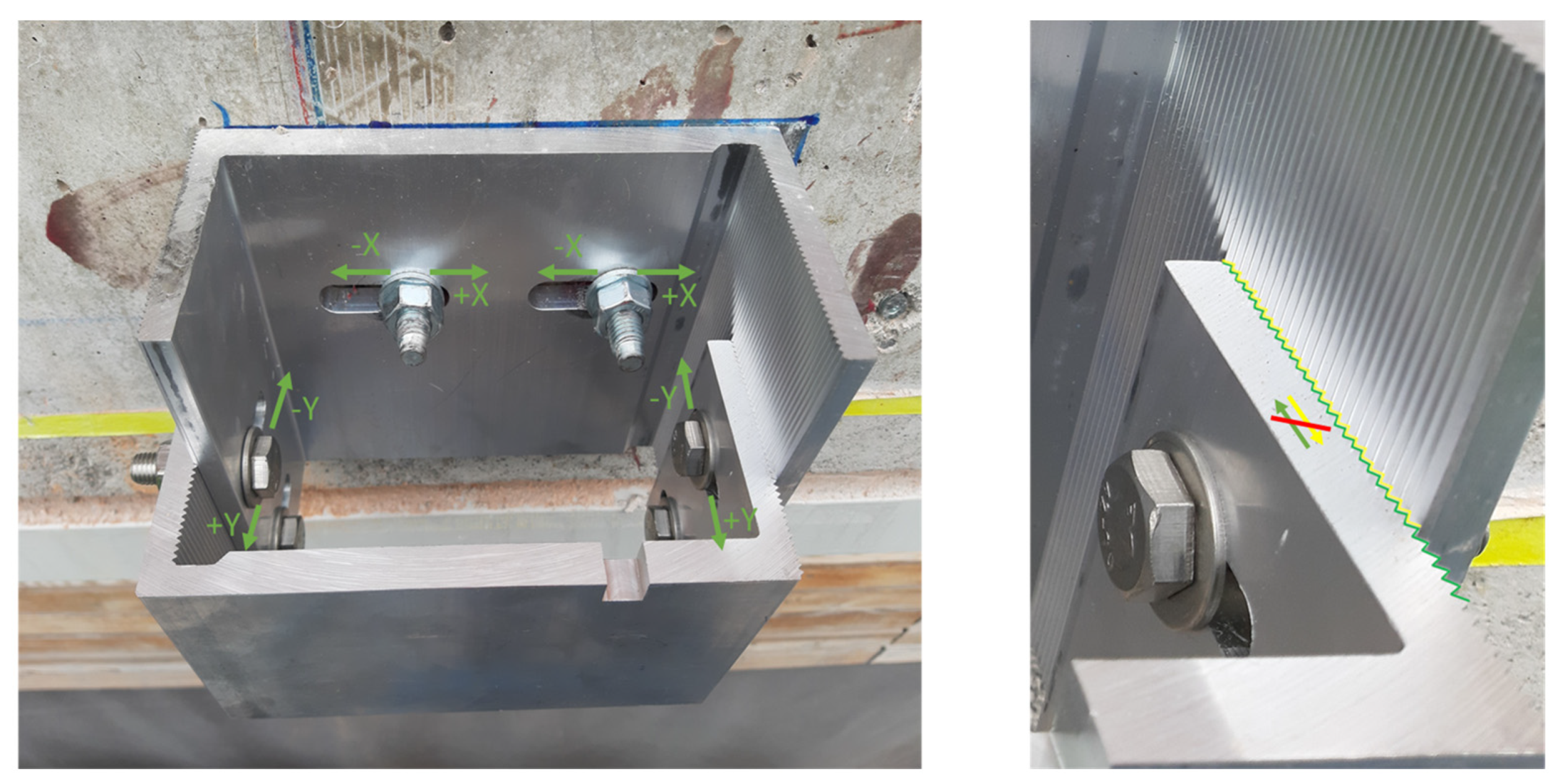
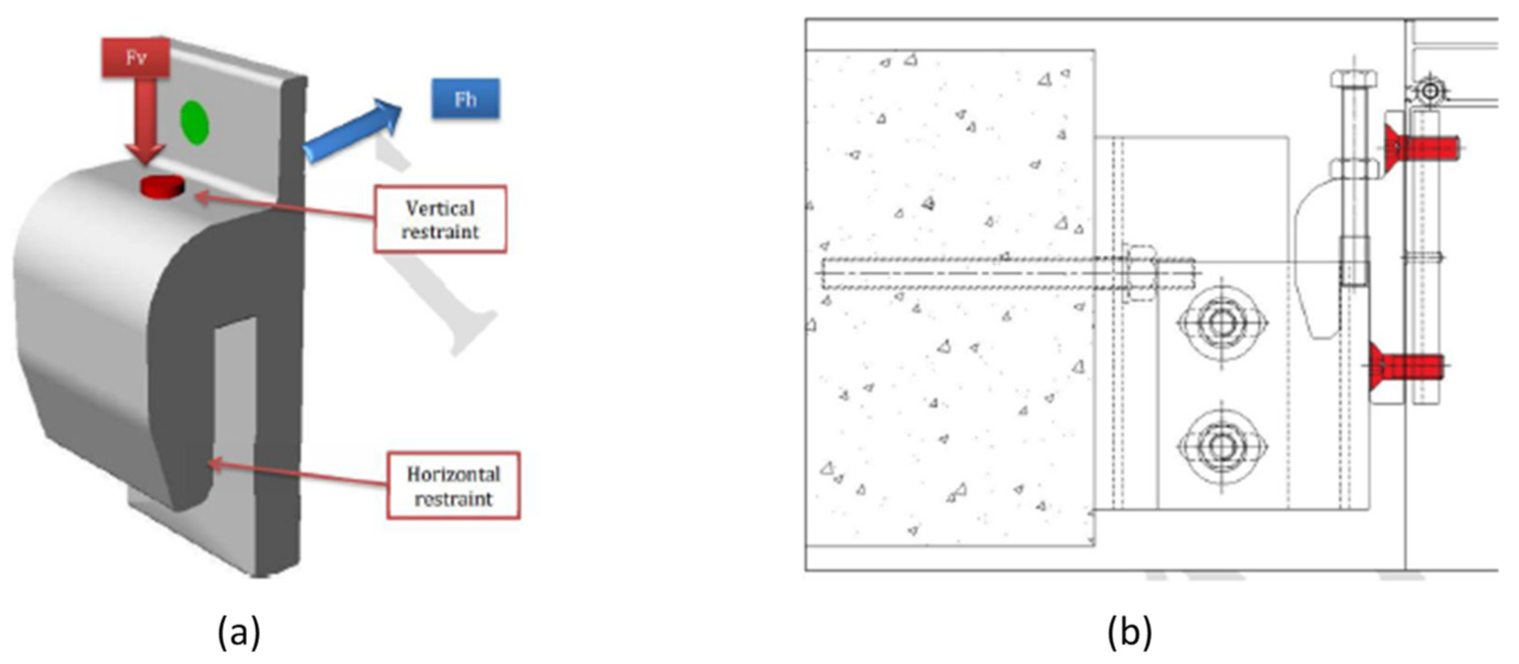
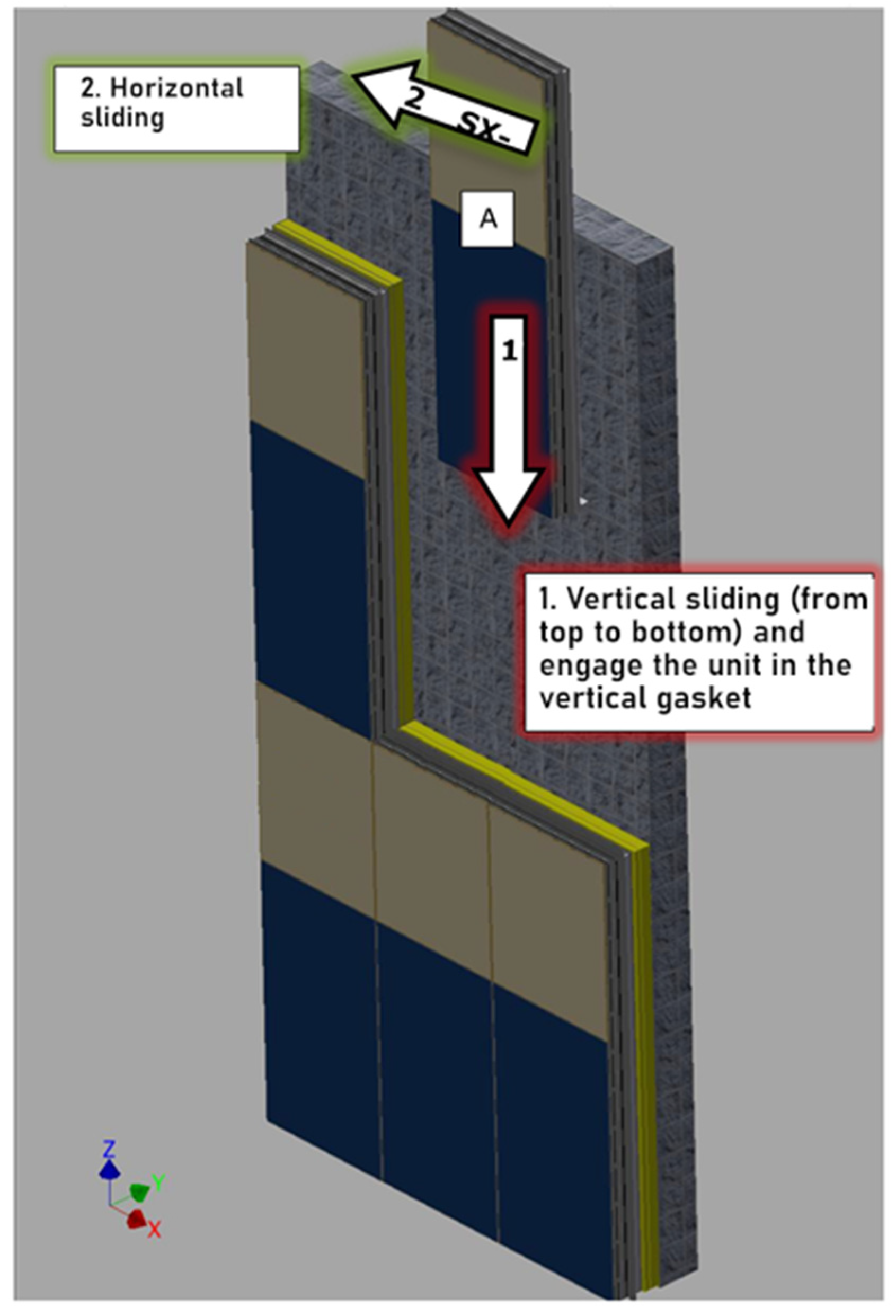
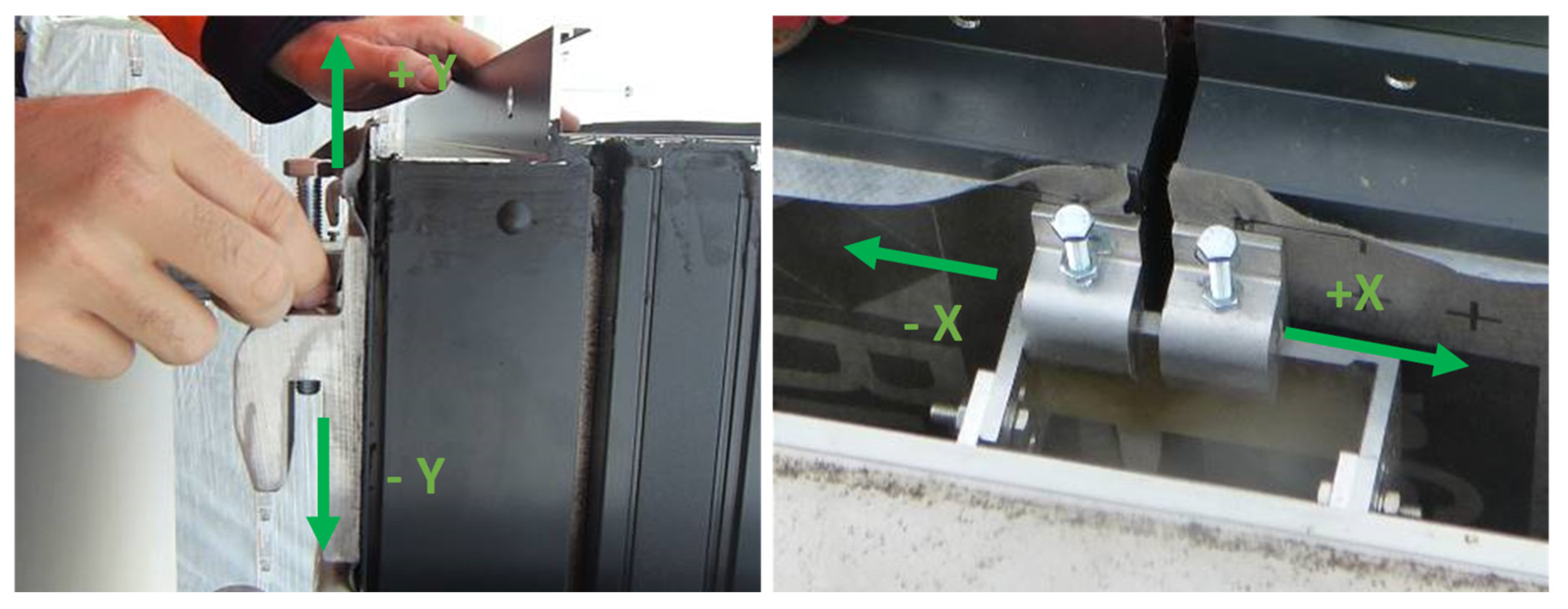
2.2. Mechanical Concept and Installation Process

The concept of the system is based on that of modular curtain wall systems, where modules are hung from anchors located in the upper area of the façade. Each panel requires two loadbearing anchor points, except for the lower panels, which are hung from four anchor points. The distance between these is defined by the width of the panel to be installed and all anchorage points have the same system and design. The assembly always starts with the lower side panels and continues with the adjacent panels, all of which are hung from four anchor points. Once the first level of panels is finished, the installation of the second level begins, which are only hung on two anchorages in the upper area and these are supported by the lower panels. The process will continue in this way until the entire surface of the facade of the building to be renovated is covered.
The structural integration with the existing buildings has a central relevance as it is critical to ensure that the building can incorporate the additional loads due to the self-weight of the modular system, wind loads and the combination of both. Each building should be studied to determine the load bearing capacity and stresses in each anchor point. Considering common restrictions, anchors will typically be attached the load bearing structure (pillar-slabs), usually made in concrete (see Figure 4 and Figure 5).
Once the anchor points are in place, the panels are raised (maximum weight 600 kg). To perform this, steel clamp with hooks are attached at the top of the panel. The main design foresees that panels are positioned with cranes. This is valid for most of the surface of the buildings, however, it has limitations in specific encounters of a building, such as the encounter of the facade with the skirt of a pitched roof. For these cases adaptations are required in the positioning of hooks and the selection of auxiliary equipment. The required adaptations are presented in Section 4 of this paper.
The anchors need to allow for adaptation to irregularities in the existing façade. Systems described by Iturralde et al. [43] or Pan et al. [50] allow for adaptation in some dimensions. However, when dealing with a fully modular façade system, very tight tolerances are required in the positioning of the panels. A specific fastening system has been designed consisting of brackets fixed to the building structure on which the façade panels are hung that allow a variable adjustment to adapt to façade irregularities, and a hanging system for the façade panels that also allows 2D in horizontal and vertical positioning of panels. This fastening system is capable of absorbing the possible irregularities and deviations of various centimeters that a flat facade may present. If the deviations are greater, it is understood that there may be a risk of collapse of the existing façade. The facade system can also be adapted and used in flat facades with recesses and protruding facade areas, however, in this case the specific situation must be analyzed in order to make the necessary modifications.
The brackets are fixed to the building structure by means of chemical or mechanical bolts. They are designed with a micro-grooved design that prevents the possible movement of components while allowing for adaptation. Another feature that differentiates this system from other modular systems on the market is the ability to absorb the irregularities of the façade offering flexibility for adjustment and installation. The anchorage for fastening to the building slab can accommodate three-dimensional adjustments between building structure and façade module in line with tolerance requirements, allowing for corrections in the X and Y directions (see Figure 4).
With horizontal adaptations guaranteed by the aforementioned anchor composition, the anchor installed in the module allows for the two-dimensional adjustment and levelling of the panel (see Figure 4, Figure 5 and Figure 6). This simple adjustment will guarantee the alignment of all the panels, and the corrections of potential deviations and lack of flatness in the existing façades.
The structural calculations of the system have been made so that the vertical distance between elements of fixation can be larger than 3 m, thus enabling the use of these panels in the renovation in almost all the building stock. In the case of Spain, residential buildings with this type of construction, with a separation between floors of around 3 m, represent 85% of the total built area [51].

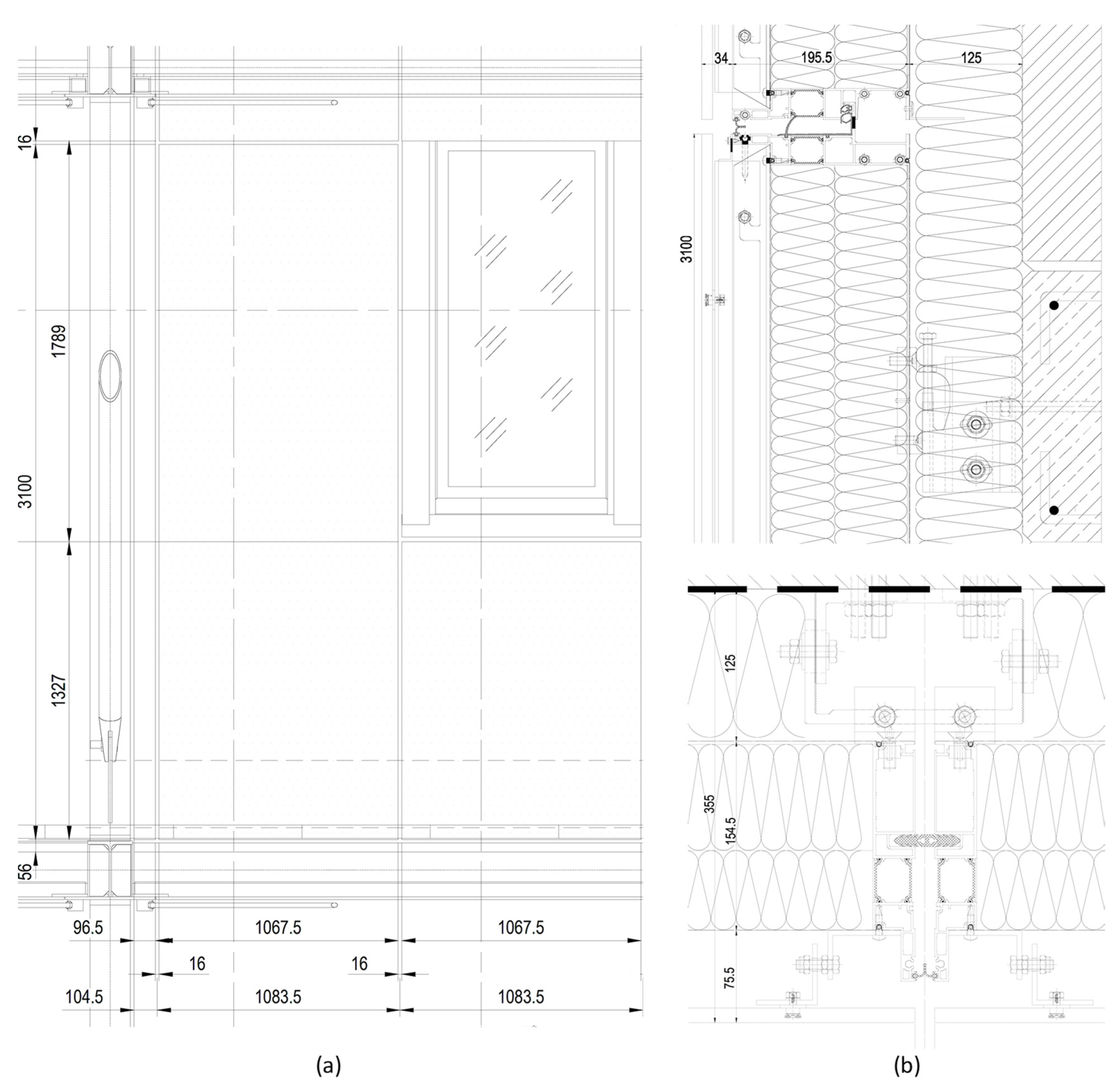
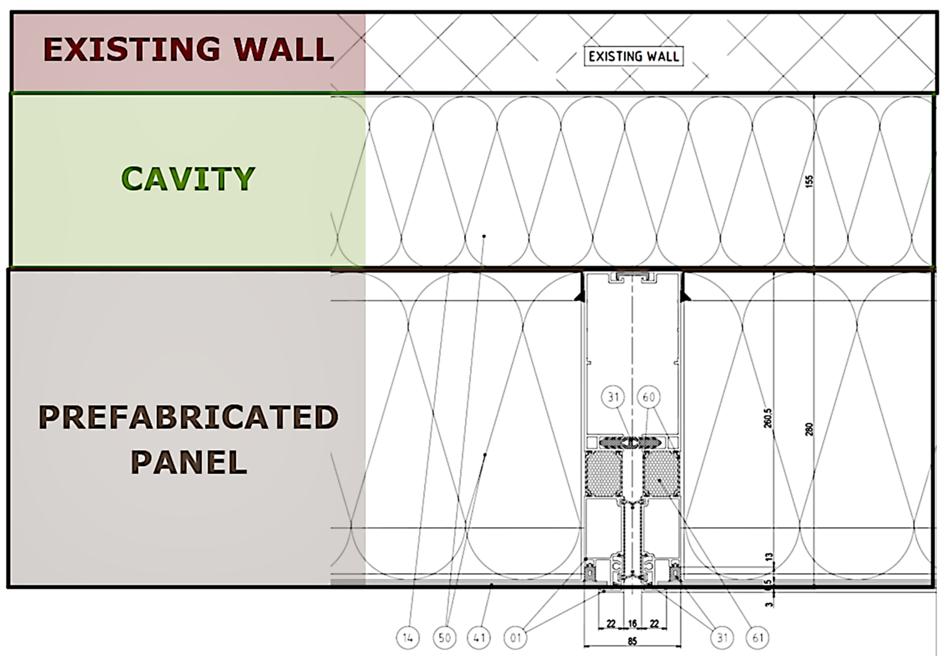
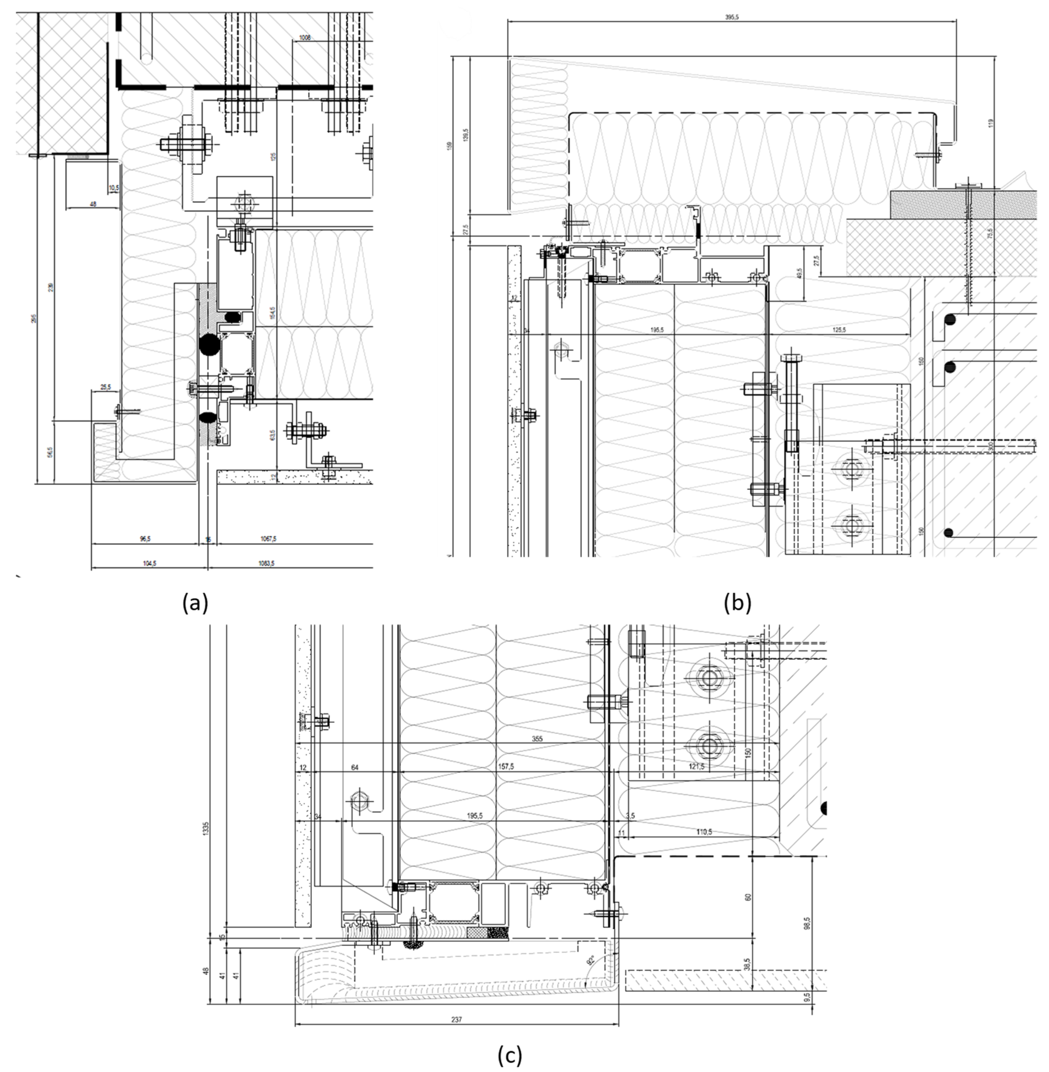
2.3. Wall Composition

The composition after the installation of the plug and play modular façade system in the building composed of three main groups or layers (see Figure 7):
  • Existing wall: This layer is not altered within the renovation process. May be composed by various sub-layers and materials. Typical constructions are brick cavity walls.
  • Cavity: This layer has a dual function of hosting the anchors and absorbing eventual tolerances of the existing wall. It can also accommodate additional ducting and piping systems. This cavity has a thickness of 125 mm. The cavity may be filled with insulation materials for thermal and acoustic performance improvement.
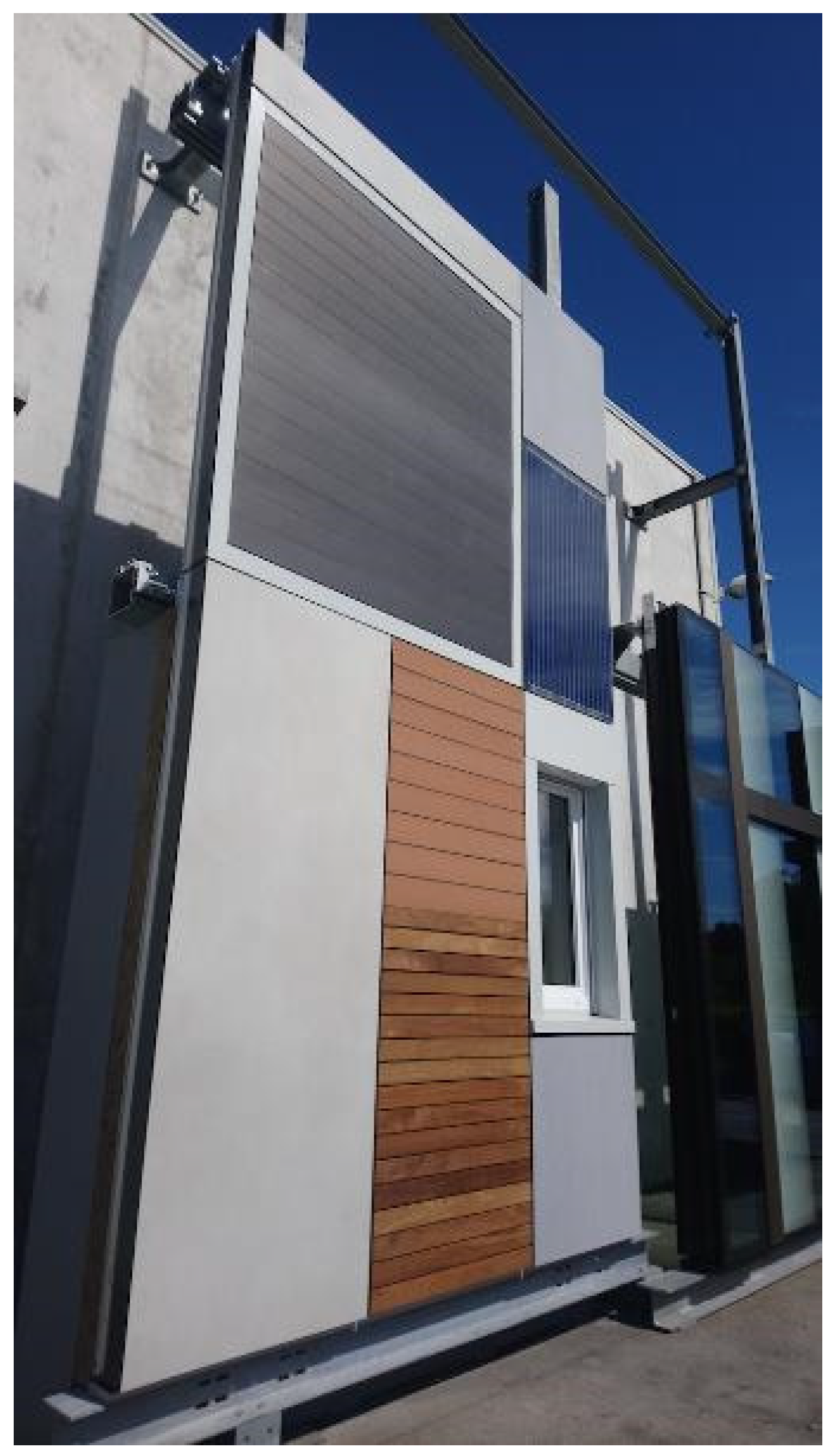
  • Modular retrofit panels: An aluminium-framed panel system with 155 mm of insulation thickness inside. It hosts a variety of aesthetic finishes, fenestration units and/or technical systems.

2.4. Variants and Additional Functionalities

The modular prefabricated unit has the potential to integrate a significant range of insulation materials, mount fenestration units and integrate various HVAC technologies and energy distribution systems as follows.

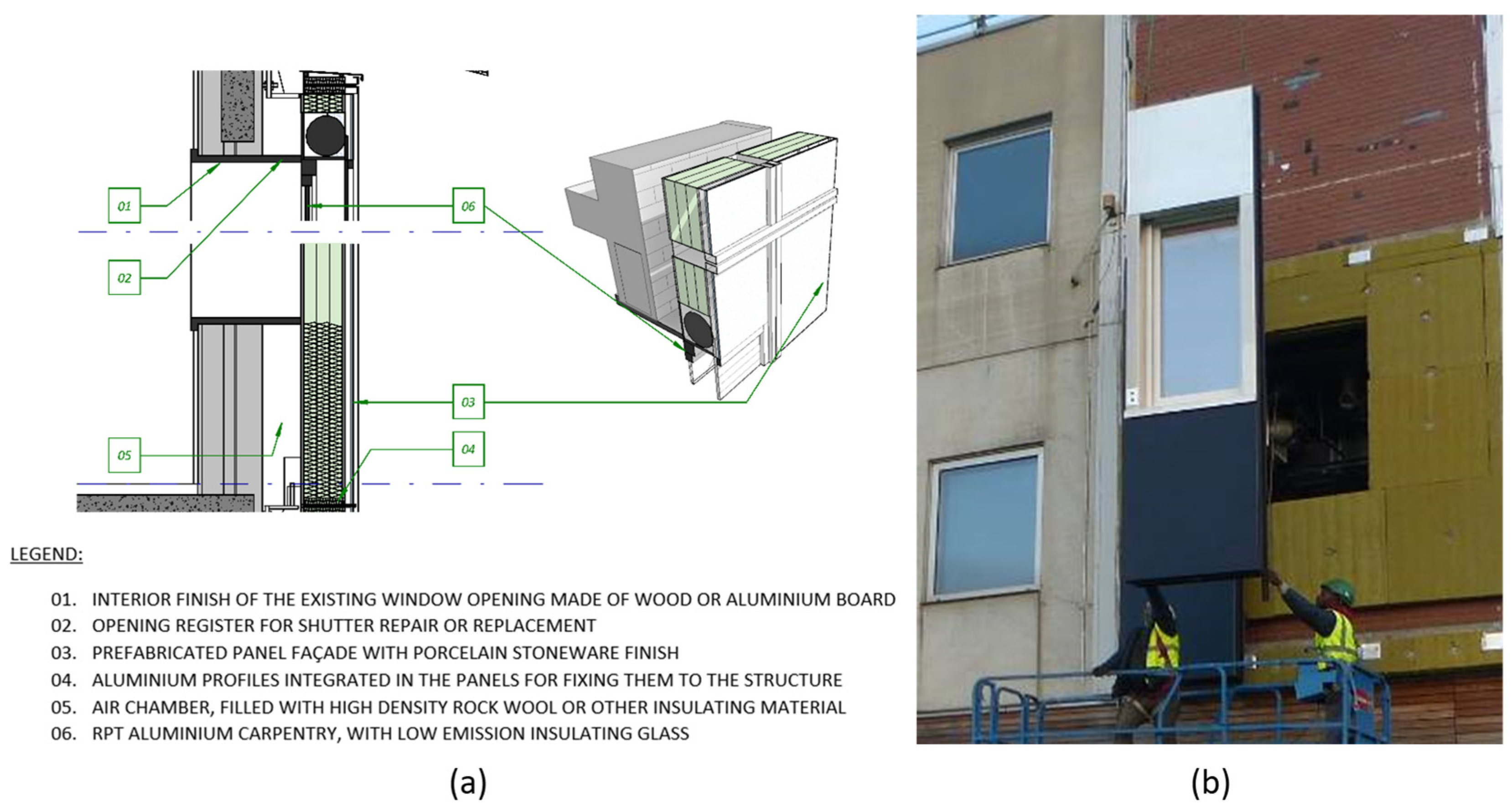
2.4.1. Fenestration Unit

The fenestration unit is based on the opaque module with an opening where a window frame module is installed. The design adapts for the possibility to integrate various framing and glazing systems, as well as shading systems such as roller shutters or venetian blinds. Original windows are removed, and a new sill is created on the inside of the window (see Figure 8).
The fenestration size is only limited by the size of the panel itself (ca 2500 × 2100 mm). These dimensions make it is easy to integrate typical window sizes in buildings to be renovated.

2.4.2. Insulation Module

The characteristics of the insulation layer can be adapted to meet the demands of specific building codes and climate zones. Most insulation materials have been proven to be adaptable, both in rigid panel and roll formats. With a thickness of 236 mm and an additional cavity insulation of 125 mm. The plug and play modular façade system allows a U-value of up to 0.09 W/(m2·K) to be achieved.

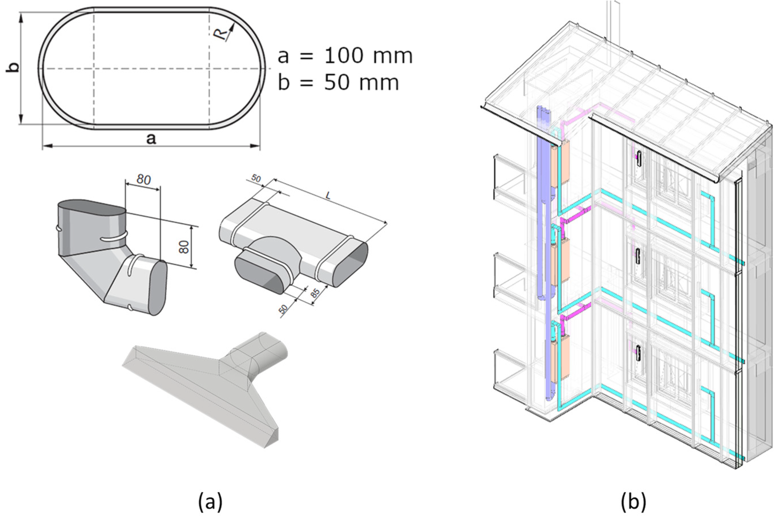
2.4.3. Ventilation Systems

The modular system allows to integrate ducts through the cavity. The air inlet in the rooms is mounted on the sides of the windows and connected to the ducts (see Figure 9).
Ventilation fans and heat recovery systems are mounted in places with good access for maintenance. Typically close to staircases, technical rooms, etc.

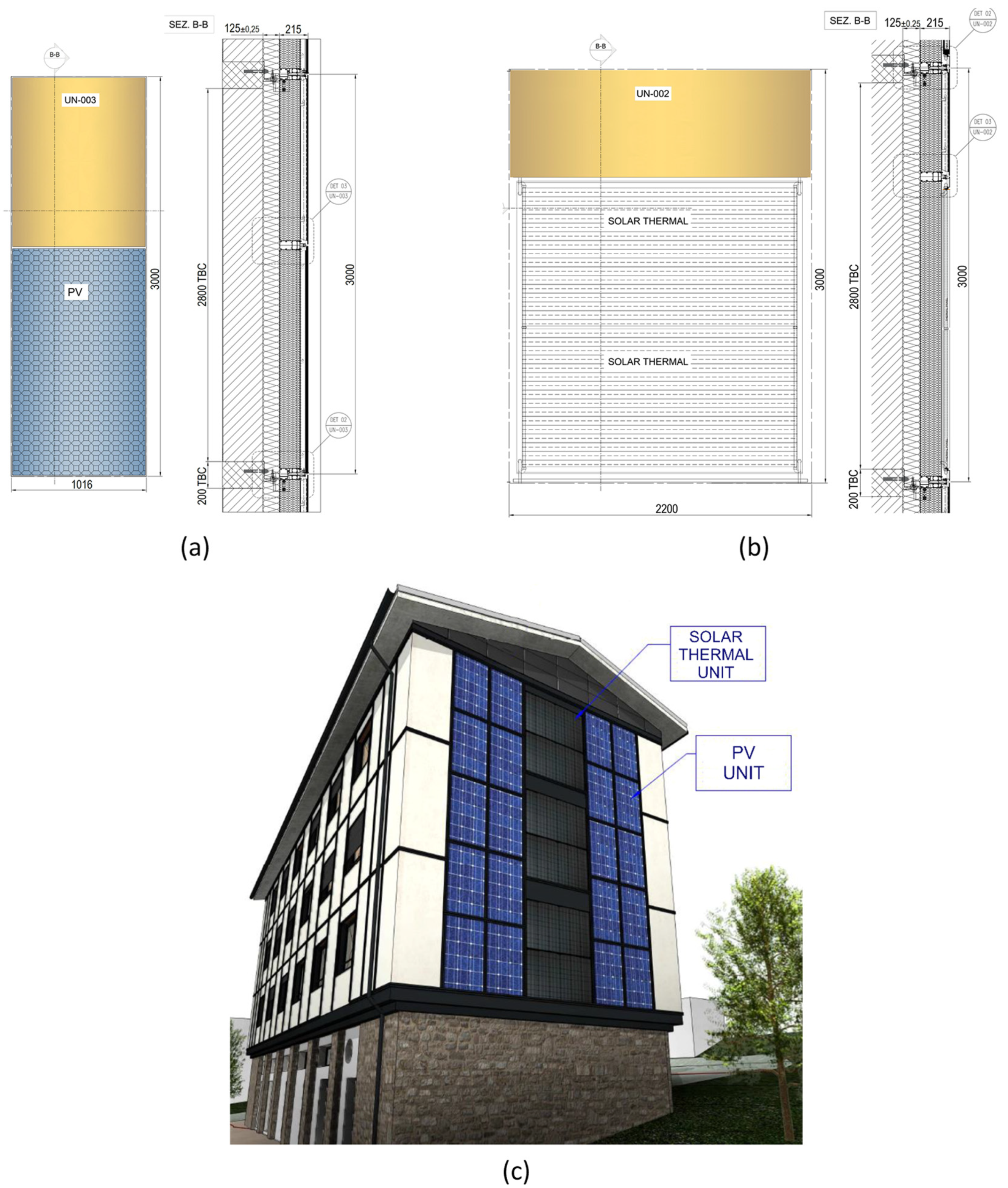
2.4.4. Building Integrated Photovoltaics (BIPV)

The integration of photovoltaics as a cladding material extends the capacity of the system, allowing for the generation of carbon-free electricity. The photovoltaic unit consists of an external PV polycrystalline glass integrating 60 PV cells covering almost all the panel surface. It has a generation potential of 315 Wp (see Figure 10).
Already being a laminated assembly, PV glass is already in agreement with the requirements of building codes towards glass, with similar mechanical and strength properties as architectural glass. The photovoltaic unit is structured in the same way as the opaque panel unit. Using the same aluminum frame anchored to the existing wall, the exterior finish is replaced by a photovoltaic system.
The wiring of the photovoltaic façade panels to the inverter, which must be located in an accessible local of the building on the first floor or under the roof, runs through the space between the original façade of the building and the prefabricated panels system.
Connection schemes to local electric networks is ruled by local regulation such as the Spanish Royal Decree-Laws 15/2018 [52] and 244/2019 [53]. This module unit in addition to insulation, hosts the battery connected to the PV installed on the envelope surface and the related electrical system.

2.4.5. Solar Thermal Systems

The solar system is an unglazed solar thermal collector integrated into a sandwich panel as an active façade, with the absorber acting as external cladding [32] (see Figure 10). This panel acts at the same time as cladding material and absorber. Capillary copper pipes (typically 20/22 mm) are melded to the metal sheet pipes. A heat transfer medium, (generally a water-glycol mixture) is circulated through capillary pipes, located on the outer metal sheet, which acts as an absorber so that solar radiation is transferred to it converted into thermal energy. Finally, the energy generated is transferred to the heat transfer system via a heat exchanger. The heat exchanger is typically located in a technical room.

2.4.6. Weatherproofing and Flashings

To ensure the watertightness of the modular façade system, the entire perimeter of the façade is closed by means of a series of profiles designed for the side, bottom and top closures. The window units already have a perimeter closure (see Figure 11). All of these end caps are designed to guarantee the tightness of the façade system and to continue with the façade insulation. All of them are composed of different aluminum pieces with a layer of thermal insulation inside to avoid thermal bridges on the perimeter of the modular system and sealing gaskets to prevent water from entering. In the case of the corner junction between two modular panels, this is solved as in a conventional ventilated facade. Depending on the type of roof of the building to be rehabilitated: flat or pitched, the design of the top finish may need to be modified.

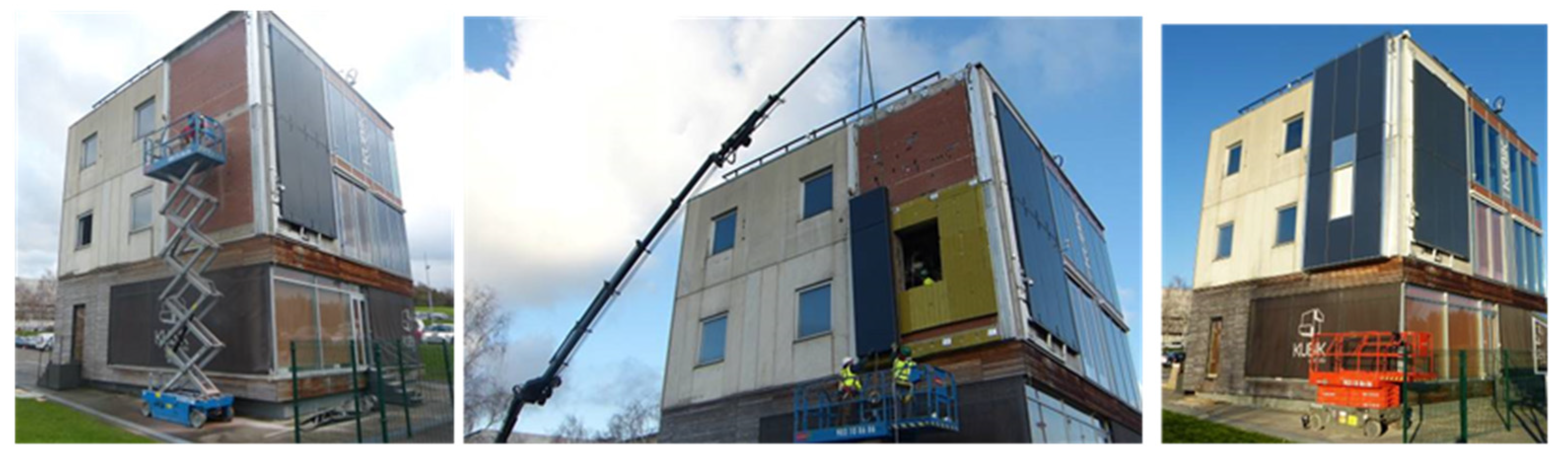
3. Early-Stage Full Scale Deployment

Transitioning from research and development to implementation in commercial projects tends to take significant time and may imply undertaking considerable risks. To minimize these risks and accelerate the escalation of the “plug and play” modular system to ready-to-use innovative façade solutions the project, an early-stage deployment was performed at the KUBIK by Tecnalia test facility (see Figure 12).
KUBIK is a full-scale experimental infrastructure for R&D on energy efficiency and testing of building envelope systems [54]. Located in the vicinity of Bilbao (Spain), KUBIK allows for the validation of systems in conditions close to those of service, in terms of architectural design, implementation and performance assessment. This building has already served as test environment for various building envelope retrofit systems [46,55,56]. Additionally, to the thermal performance, it also allows to evaluate and develop the assembly and erection procedures, especially for industrialized solutions such as the “plug and play” modular construction system [48,57].
In this case, specific focus was made in testing design, construction and assembly processes and guidance for on-site crews. The test setup has consisted of a two-floor façade section with an area of more than 20 m2. Five opaque panel units and one panel with a window have been used.
This test was used to validate critical points in the installation process. The full installation procedure was tested, including the installation of anchors in the façade, hanging of façade elements on them and sealing of junctions, and the entire assembly process was checked. A validation protocol was set so that the system proved to be adaptable to variations in anchor locations in 3D, allowed access for the assembly team to perform such adaptations and resulted in a satisfactory seal of junctions.

4. Retrofit of a Real Building

A multi-dwelling residential building located in Durango (Spain) has been retrofitted. Durango classifies as an oceanic climate (Cfb) according to the Köppen climate classification [58]. The annual average temperature is 14 °C. In summer, the daily average temperature is below 20 °C, so cooling systems are generally unnecessary, particularly if measures such as solar shading or night cooling are implemented.

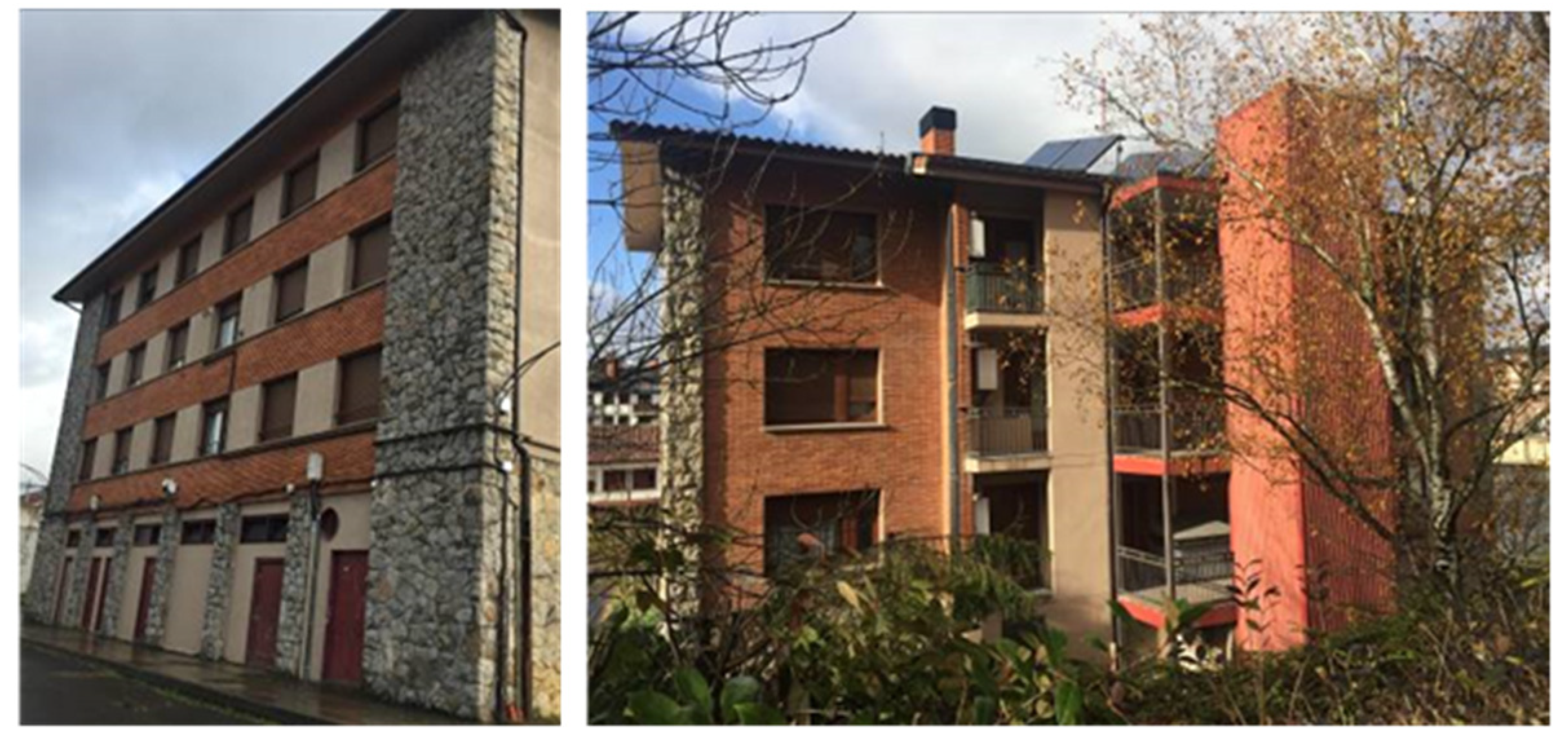
4.1. Pre-Intervention Status
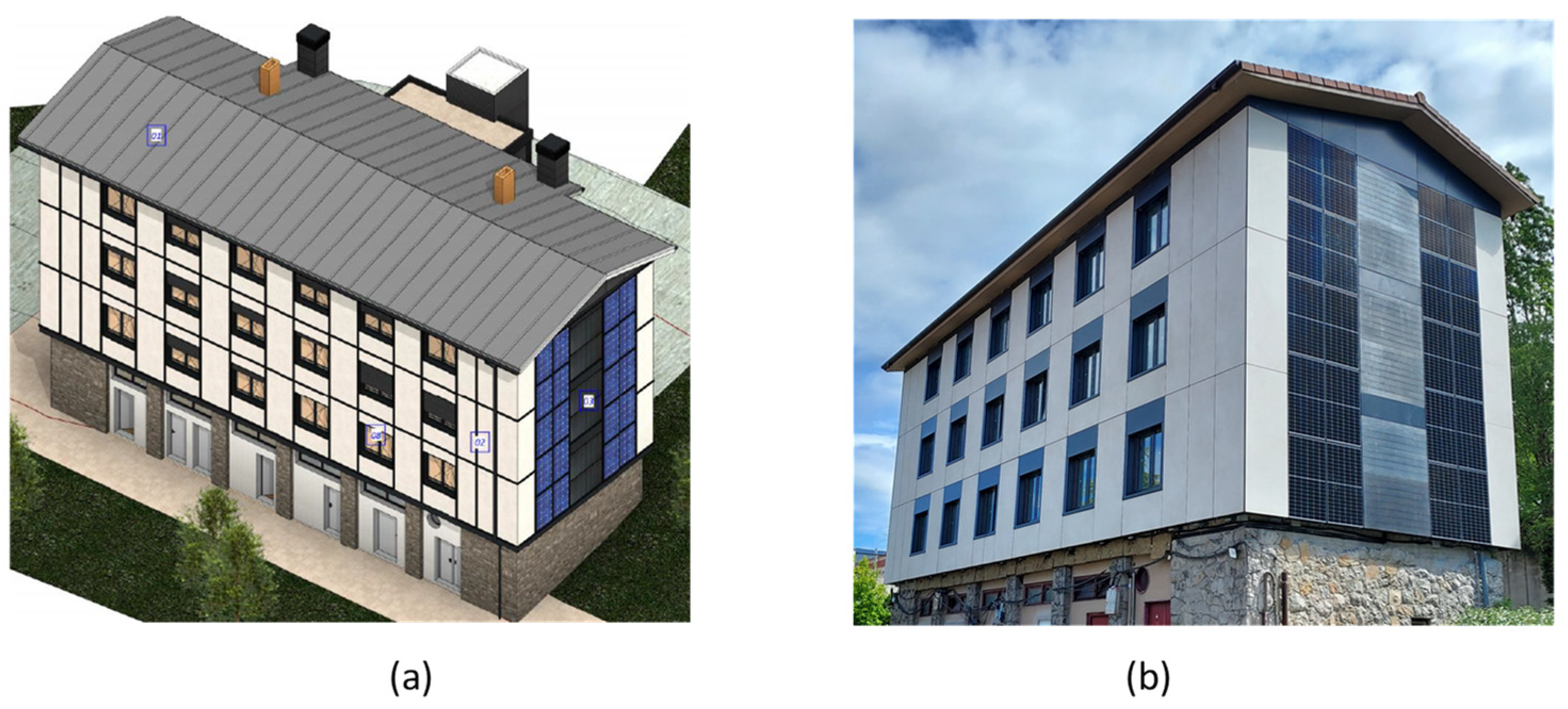
The building consists of a three-floor residential building with seven apartments, with an exempt rectangular floor plan (22 m × 9 m) and 12.00 m in height, a gross area of 792 m2 and net space conditioned area of 374 m2 (see Figure 13).
The apartments were heated by individual natural gas boilers serving space heating and domestic hot water (DHW) services. All apartments were naturally ventilated and lacked mechanical ventilation or cooling. No renewable energy systems were installed.
Originally built in 1965 with a reinforced concrete structure. The façades consist of a cavity wall comprising, an outer hollow brick layer, a layer of waterproof cement, air chamber, an interior hollow brick layer and 3 cm of plaster, with an estimated U value of 1.49 W/(m2·K). The facades have an exterior face brick finish with natural stone in the edges.
The four-slope roof is formed from poplar partitions and with and exterior closure in curved ceramic tile with a U value of 0.9 W/(m2·K). Regarding fenestration, double glazing windows with estimated U-value of 2.73 W/(m2·K) are present. These values do not meet the minimum requirements specified by current national building regulations [59].

4.2. Intervention

Although other studies have used other tools, applications or methodologies to perform building energy assessments [60,61], due to the accuracy and possibilities it offers for integrating building usage data, this study has selected the use of Design Builder [62] along with its simulation engine EnergyPlus to perform the energy assessments of the real building retrofit. Simulation schedules for the energy performance calculation can generally be derived from the building regulations. In this study, parameters such as the heating setpoint, infiltrations, ventilation rate, occupancy rate, schedules, and internal gains have been taken from Spanish building regulations [59]. In this work, design alternatives were tested, and the configuration defined below was chosen (see Figure 14).
A façade intervention with the plug and play modular façade system in 416 m2 was designed, comprising 75 opaque panels, 30 panels with windows, 20 PV modules and 6 solar thermal panels.
Total insulation levels in opaque panels of 0.2 W/(m2·K) were achieved with 12 cm high density rock wool insulation. PVC-framed window frames with U value of 1.8 W/(m2·K) were used to mount double low-emission glazing units with a U value of 1.1 W/(m2·K).
PVGIS was used to design and size the PV field [55]. With a target value of producing 39.5% of the thermal energy linked to the DHW load (19 kWh/m2) and 48% of electrical load in the building (9500 kWh/yr). A total of 20 panels in the south facade of the building with 90° inclination and 10° azimuth with a total area of 52 m2 were selected for this purpose.
Due to the renovation of the facade and windows, the proposed new facade will be much more airtight, for this reason a mechanical air ventilation system with heat recovery has been installed. This system integrates the ducts into the facade cavity and has air inlets in the rooms at the sides of the windows. The fans and heat recovery systems have been installed on the terraces and balconies of the dwellings.
Considering energy improvements associated to the integration of the ventilation system, PV and solar thermal heat production, along with the refurbishment of the roof, the initial heating load of 110 kWh/m2 is reduced by 86% down to 14.5 kWh/m2.

4.3. Façade Inspection, Modulation and Positioning of Anchors

As any other modular system, accurate information is required for its design and manufacture process. Although flexible, modules impose much higher limitations in the installation process compared to other traditional systems. It is necessary to carry out a layout of all its components, panel modules and fastening systems in the design phase. Relying on a real model obtained from a point cloud can facilitate the task of accurately setting out the anchorages.
Although the system allows correcting both irregularities of the facade and deviations produced in the installation of the anchors, the staking out of the anchors must be performed meticulously. For large façade spans, the accumulation of small deviations in each junction can cause that in the case of a window panel it does not coincide exactly with the real opening of the building. For this reason, special care must be taken in the installation of window panel modules.
With regards to system mechanics, the anchors were adapted and verified to be strong enough to support the actions produced by the panel system. In this particular case, a system with six chemical fixings were used for each anchor, whose performance was defined through the Hilti Profis Anchor software [63]. Anchors were prescribed at horizontal distances of 1.35 to 1.7 m, depending on the type of panel installed. In all cases, vertical distance was set to be equal to the slab-to-slab height.

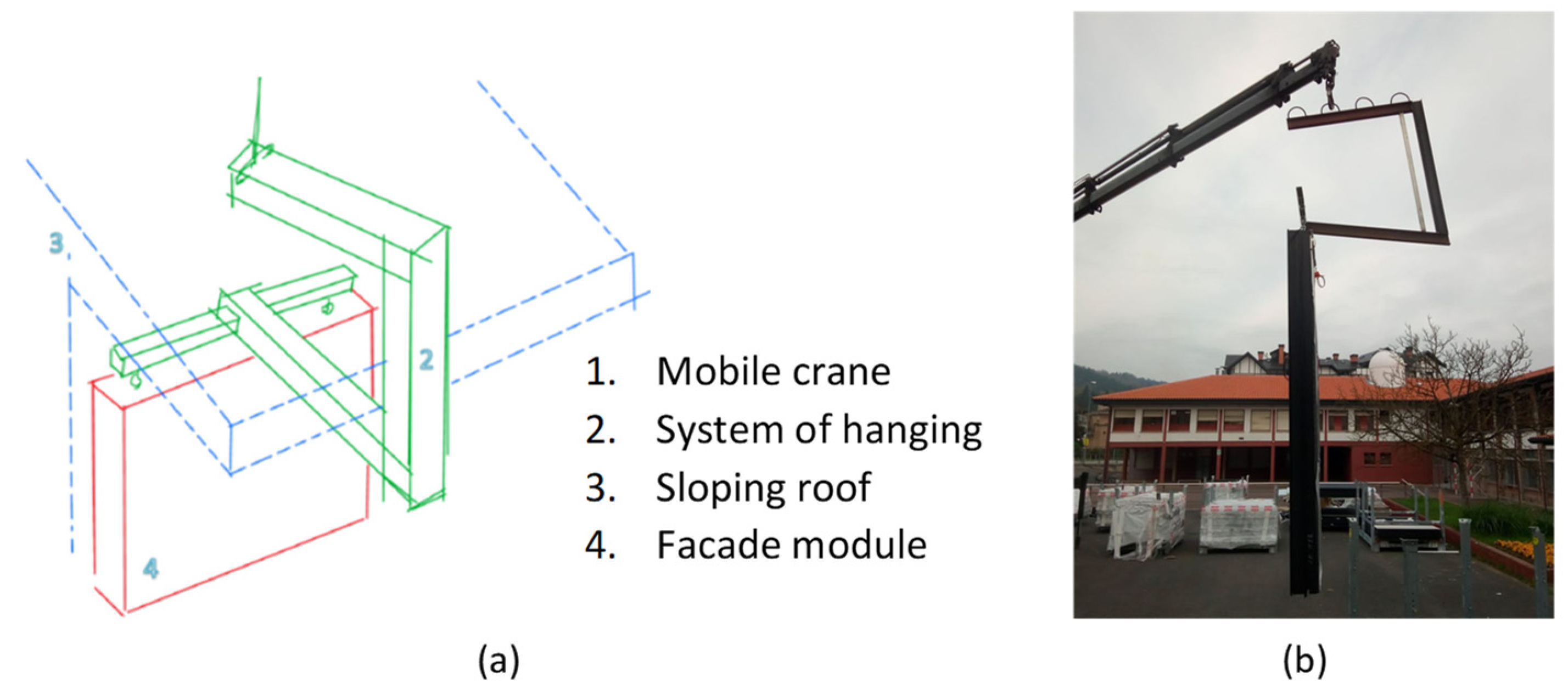
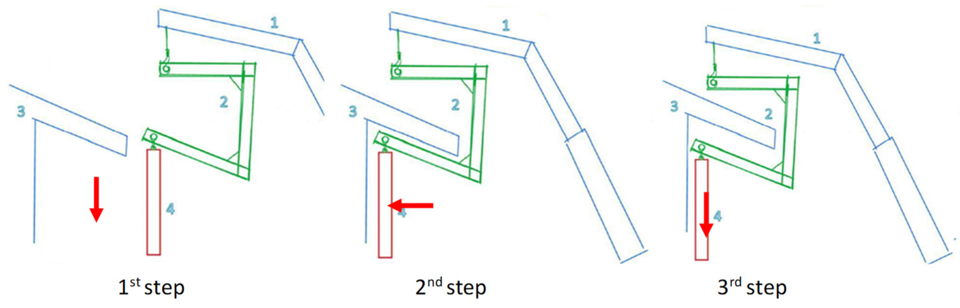
4.4. Installation Process

The erection process developed and tested in the early-stage deployment was found to be successful also in most cases also for the real building. However, incompatibilities were identified in the eaves of the pitched roof. In these locations, the standard installation with a standard crane system was not possible, as the roof overhang prevented the panels from getting close to the brackets anchored to the structure.
It was necessary to modify the fastening process of the upper façade panels. A special tool that avoided the roof eaves was developed. This tool allowed to bring the panels closer to the facade, avoiding the roof eaves, and to proceed with their fastening.
The designed tool and the installation process are shown in the Figure 15 and Figure 16. An initial first horizontal movement brings the panel closer to the façade, and a second vertical movement hangs the panels from the anchorage systems.

5. Advantages and Savings

The proposed system not only allows to integrate fenestration and various HVAC technologies, but is also expected to deliver cost reductions to the building renovation process. Economic savings are achieved in the use of materials, execution time and labor intensity.
A reduction in the materials used is achieved, as all surplus material is recycled or re-used as part of an industrial process. Based on the authors’ experience, which has been involved in the design and execution management of various energy refurbishment projects throughout their careers outside of research, the modular facade system was expected to perform reductions in cladding materials (30%), insulation boards (20%) and construction waste (25%). These savings have been verified in the retrofit of a real building. The façade modules are completely prefabricated, so it has not been necessary to cut the cladding material, as is the case in conventional ventilated façade renovations. In these cases, in the window joints, corners and perimeter of the facade, it is necessary to cut the cladding pieces to adapt them to the geometry, producing a waste of material that has not occurred with the modular façade system presented in this paper. The same occurs with the insulating material. As it is included in the modular panel itself, there has been no waste of insulating material to adapt it to the geometry of the building. Regarding construction waste, as all the elements that make up the façade system (profiles, trims, anchors, insulation material, etc.) are included inside the façade modules, not so much construction waste has been generated during assembly.
A reduction in the execution time, labor and auxiliaries is expected thanks to the “plug and play” concept. The substructure of the system is simpler than in a conventional ventilated facade system. In addition, the prefabricated “plug and play” system allows for quick and easy assembly of the facade, and of cranes are used instead of scaffolding. Altogether, this leads to estimations of time reductions in the range of 40–50% lower than in a ventilated facade system.
The aforementioned reductions were verified in the demonstration building. Installation times for ventilated facades of similar size (~300 m2) typically require four months of construction with three to four workers. This timespan includes the time for the assembly of scaffolding, layout and assembly of substructure, installation of thermal insulation, installation of finishing material and final finishing. In the demonstration site, the erection of the panels was performed much faster. Approximately, two months were required for the installation of the anchors and the installation of the panels. Additionally, two weeks were required for the removal of existing windows and the restoration of the window sills.
In addition to saving time, the modular system also allows for considerable savings in auxiliary equipment. For its installation it is not necessary to assemble a tubular scaffolding, with the time and cost that this represents. This system only needs a scissor lifts or a platform lift to access work area from externally, depending on the height of the building to be renovated, one or the other equipment will be used and a mobile crane/telescopic handler to lift the units during installation.

6. Discussion and Conclusions

The modular “plug and play” facade system presented in this paper responds to the need for renovation packages for buildings. It facilitates the improvement of the building fabric, incorporating insulation, providing air-tightening and allowing integration of building services and solar technologies. The proposed concept allows a simple and fast way to carry out the renovation of an existing building to nZEB performance levels, reducing the final duration of the on-site operations of the renovation work with the consequent reduction of the work costs. Time saving are known to have a great impact and economic savings in countries with high labor costs.
The design, construction, manufacture and installation cycle, and the solution of anchoring and fixing of the modular “plug and play” facade system has been tested in a real environment. Reductions in execution time and auxiliary equipment have been verified.
The implementation of the “plug and play” modular facade system at full-scale in KUBIK has served to validate the system under controlled conditions and remove uncertainty from the escalation process.
The current design allows for a separation between the fixings of about 3 m, which is considered to be in good agreement with its proposed application to the renovation of residential building blocks. This system could be adapted to other building typologies with similar geometric configurations.
The fixation system developed for the system allows for adaptation to the common irregularities in existing walls, so that the plug and play system can be applied under real conditions. With the possibility to correct for irregularities any irregularities in the façade deviations in the placement of brackets or connectors, large areas of facade can be installed quickly and easily in a short period of time, reducing the final duration of the on-site operations of the renovation work.
System mechanics has been validated against requirements in building codes. However, the authors’ acknowledge that a proper structural analysis of the existing wall needs to be performed so that its load bearing capacity is guaranteed and it is necessary to resolve how the modular facade system are integrated in the building’s system, considering all the adjacent elements, such as wall-to-roof junction.
In the retrofit of a real building, it has been necessary to modify the system of hanging the panels in order to be able to carry out the installation because the sloping roof prevented the vertical displacement of the panel for its fixation on the façade, which has posed a significant challenge for the definition of a system to hang the panels, but will be replicable for any other building with this type of roof.

Author Contributions

Conceptualization, J.T., R.G.-M., A.U.-A., and A.P.; methodology, A.U.-A., J.I.T.-G., A.P., O.C. and N.A.; validation, J.T., J.I.T.-G., A.U.-A., A.P., O.C., S.M., N.A. and A.M.C.; formal analysis, J.T., S.M., N.A., A.M.C.; investigation, J.T., X.O., R.G.-M. and J.I.T.-G.; writing original draft preparation, J.T., R.G.-M. and X.O.; writing review and editing, J.T., R.G.-M. and X.O. All authors have read and agreed to the published version of the manuscript.

Funding

This project has received funding from the European Union’s Horizon 2020 research and innovation programme under grant agreement No 768718.

Institutional Review Board Statement

Not applicable.

Informed Consent Statement

Not applicable.

Data Availability Statement

Data sharing is not applicable to this article.

Conflicts of Interest

The authors declare no conflict of interest.

References

  1. Venice Charter. International Charter for the Conservation and Restoration of Monuments and Sites. In Proceedings of the IInd International Congress of Architects and Technicians of Historic Monuments, Venice, Italy, 25–31 May 1964. [Google Scholar]
  2. International Agency of Energy. Available online: https://www.iea.org/data-and-statistics?country=EU28&fuel=Energy%20consumption&indicator=TFCShareBySector (accessed on 16 July 2021).
  3. Power, A. Does demolition or refurbishment of old and inefficient homes help to increase our environmental, social and economic viability? Energy Policy 2008, 36, 4487–4501. [Google Scholar] [CrossRef]
  4. European Union. Directive (EU) 2018/844 of the European Parliament and of the Council of 30 May 2018. Amending Directive 2010/31/EU on the Energy Performance of Buildings and Directive 2012/27/EU on Energy Efficiency. 2018. Available online: https://eur-lex.europa.eu/legal-content/EN/TXT/PDF/?uri=CELEX:32018L0844&from=EN (accessed on 21 March 2020).
  5. Capros, P.; Mantzos, L.; Tasios, N.; De Vita, A.; Kouvaritakis, N. EU Energy Trends to 2030; Update 2009; Publications Office of the European Union: Luxembourg, 2010. [Google Scholar] [CrossRef]
  6. European Commission COM 112 Final. A Roadmap for Moving to a Competitive Low Carbon Economy in 2050. 2011. Available online: https://eur-lex.europa.eu/LexUriServ/LexUriServ.do?uri=COM:2011:0112:FIN:EN:PDF (accessed on 16 July 2021).
  7. European Commission. The Strategic Energy Technology (SET) Plan. 2017. Available online: https://publications.europa.eu/en/publication-detail/-/publication/771918e8-d3ee-11e7-a5b9-01aa75ed71a1/language-en/format-PDF/source-51344538. (accessed on 16 July 2021).
  8. European Commission. Energy, Climate Change, Environment, Climate Action. Available online: https://ec.europa.eu/clima/policies/strategies_en (accessed on 1 July 2020).
  9. Castellazzi, L.; Zangheri, P.; Paci, D.; Economidou, M.; Labanca, N.; Ribeiro, T.; Panev, S.; Zancanella, P.; Broc, J.S. Assessment of Second Long-Term Renovation Strategies under the Energy Efficiency Directive, EUR 29605 EN; Publications Office of the European Union: Luxembourg, 2019. [Google Scholar] [CrossRef]
  10. RICS. Building Stock in the EU: Energy Efficient Retrofits in Renovations. Available online: https://www.rics.org/es/news-insight/latest-news/news-opinion/building-stock-in-the-eu-energy-efficient-retrofits-in-renovations/ (accessed on 25 August 2021).
  11. Oregi, X.; Hernandez, P.; Hernandez, R. Analysis of life-cycle boundaries for environmental and economic assessment of building energy refurbishment projects. Energy Build. 2017, 136, 12–25. [Google Scholar] [CrossRef]
  12. Loga, T.; Stein, B.; Diefenbach, N. TABULA building typologies in 20 European countries—Making energy-related features of residential building stocks comparable. Energy Build. 2016, 132, 4–12. [Google Scholar] [CrossRef]
  13. Junghans, L. Sequential equi-marginal optimization method for ranking strategies for thermal building renovation. Energy Build. 2013, 65, 10–18. [Google Scholar] [CrossRef]
  14. Nicolae, B.; George-Vlad, B. Life cycle analysis in refurbishment of the buildings as intervention practices in energy saving. Energy Build. 2015, 86, 74–85. [Google Scholar] [CrossRef]
  15. Konstantinou, T.; Knaack, U. An approach to integrate energy efficiency upgrade into refurbishment design process, applied in two case-study buildings in Northern European climate. Energy Build. 2013, 59, 301–309. [Google Scholar] [CrossRef]
  16. Pombo, O.; Rivela, B.; Neila, J. The challenge of sustainable building renovation: Assessment of current criteria and future outlook. J. Clean. Prod. 2016, 123, 88–100. [Google Scholar] [CrossRef]
  17. Kamari, A.; Corrao, R.; Kirkegaard, P.H. Sustainability focused decision-making in building renovation. Int. J. Sustainability Built Environ. 2017, 6, 330–350. [Google Scholar] [CrossRef] [Green Version]
  18. Passer, A.; Ouellet-Plamondon, C.; Kenneally, P.; John, V.; Habert, G. The impact of future scenarios on building refurbishment strategies towards plus energy buildings. Energy Build. 2016, 124, 153–163. [Google Scholar] [CrossRef]
  19. Franco, G.; Magrini, A.; Cartesegna, M.; Guerrini, M. Towards a systematic approach for energy refurbishment of historical buildings. The case study of Albergo dei Poveri in Genoa, Italy. Energy Build. 2015, 95, 153–159. [Google Scholar] [CrossRef]
  20. Todorović, M.S.; Ećim-Đurić, O.; Nikolić, S.; Ristić, S.; Polić-Radovanović, S. Historic building’s holistic and sustainable deep energy refurbishment via BPS, energy efficiency and renewable energy—A case study. Energy Build. 2015, 95, 130–137. [Google Scholar] [CrossRef]
  21. Buda, A.; de Place Hansen, E.J.; Rieser, A.; Giancola, E.; Pracchi, V.; Mauri, S.; Marincioni, V.; Gori, V.; Fouseki, K.; López, C.P.; et al. Conservation-Compatible Retrofit Solutions in Historic Buildings: An Integrated Approach. Sustainability 2021, 13, 2927. [Google Scholar] [CrossRef]
  22. Marincioni, V.; Gori, V.; de Place Hansen, E.J.; Herrera-Avellanosa, D.; Mauri, S.; Giancola, E.; Egusquiza, A.; Buda, A.; Leonardi, E.; Rieser, A. How Can Scientific Literature Support Decision-Making in the Renovation of Historic Buildings? An Evidence-Based Approach for Improving the Performance of Walls. Sustainability 2021, 13, 2266. [Google Scholar] [CrossRef]
  23. Pickles, D.; McCaig, I. Energy Efficiency and Historic Buildings: How to Improve Energy Efficiency; Historic England: London, UK, 2018. [Google Scholar]
  24. Ortiz, J.; Fonseca, A.; Salom, J.; Garrido, N.; Fonseca, P.; Russo, V. Comfort and economic criteria for selecting passive measures for the energy refurbishment of residential buildings in Catalonia. Energy Build. 2016, 110, 195–210. [Google Scholar] [CrossRef]
  25. Ferreira, M.; Almeida, M.; Rodrigues, A. Impact of co-benefits on the assessment of energy related building renovation with a nearly-zero energy target. Energy Build. 2017, 152, 587–601. [Google Scholar] [CrossRef]
  26. Brouwers, J.; Entrop, A.G. New triplet visions on sustainable building, in: Action for Sustainability. In Proceedings of the 2005 World Sustainable Building Conference, Tokyo, Japan, 27–29 September 2005; pp. 4330–4335. [Google Scholar]
  27. Entrop, A.G.; Brouwers, H.J.H. Assessing the sustainability of buildings using a framework of triad approaches. J. Build. Apprais. 2010, 5, 293–310. [Google Scholar] [CrossRef]
  28. Martinez, R.G.; Goiti, E.; Reichenauer, G.; Zhao, S.; Koebel, M.; Barrio, A. Thermal assessment of ambient pressure dried silica aerogel composite boards at laboratory and field scale. Energy Build. 2016, 128, 111–118. [Google Scholar] [CrossRef]
  29. Uriarte, A.; Garai, I.; Ferdinando, A.; Erkoreka, A.; Nicolas, O.; Barreiro, E. Vacuum insulation panels in construction solutions for energy efficient retrofitting of buildings. Two case studies in Spain and Sweden. Energy Build. 2019, 197, 131–139. [Google Scholar] [CrossRef]
  30. Dermentzis, G.; Ochs, F.; Siegele, D.; Feist, W. Renovation with an innovative compact heating and ventilation system integrated into the façade—An in-situ monitoring case study. Energy Build. 2018, 165, 451–463. [Google Scholar] [CrossRef]
  31. Dugué, A.; Raji, S.; Bonnamy, P.; Bruneau, D. E2VENT: An Energy Efficient Ventilated Façade Retrofitting System. Presentation of the Embedded LHTES System. Procedia Environ. Sci. 2017, 38, 121–129. [Google Scholar] [CrossRef]
  32. Elguezabal, P.; Lopez, A.; Blanco, J.M.; Chica, J.A. Assessment on the Efficiency of an Active Solar Thermal Facade: Study of the Effect of Dynamic Parameters and Experimental Analysis When Coupled/Uncoupled to a Heat Pump. Energies 2020, 13, 597. [Google Scholar] [CrossRef] [Green Version]
  33. Elguezabal, P.; Garay, R.; Martinez, R.G. Experimentation under real performing conditions of a highly integrable unglazed solar collector into a building façade. Energy Procedia 2017, 122, 775–780. [Google Scholar] [CrossRef] [Green Version]
  34. Hejtmánek, P.; Volf, M.; Sojková, K.; Brandejs, R.; Kabrhel, M.; Bejček, M.; Novák, E.; Lupíšek, A. First Stepping Stones of Alternative Refurbishment Modular System Leading to Zero Energy Buildings. Energy Procedia 2017, 111, 121–130. [Google Scholar] [CrossRef]
  35. D’Oca, S.; Ferrante, A.; Ferrer, C.; Pernetti, R.; Gralka, A.; Sebastian, R.; Veld, P.O. ‘T Technical, Financial, and Social Barriers and Challenges in Deep Building Renovation: Integration of Lessons Learned from the H2020 Cluster Projects. Buildings 2018, 8, 174. [Google Scholar] [CrossRef] [Green Version]
  36. Fenner, A.E.; Zoloedova, V. Conference Report 2017: State-of-the-Art of Modular Construction; Rinker School of Construction Management University of Florida: Gainesville, FL, USA, 2017. [Google Scholar]
  37. Bystedt, A.; Östman, L.; Knuts, M.; Johansson, J.; Westerlund, K.; Thorsen, H. Fast and Simple—Cost Efficient Façade Refurbishment. Energy Procedia 2016, 96, 779–787. [Google Scholar] [CrossRef] [Green Version]
  38. Callegari, G.; Spinelli, A.; Bianco, L.; Serra, V.; Fantucci, S. NATURWALL©—A Solar Timber Façade System for Building Refurbishment: Optimization Process through in Field Measurements. Energy Procedia 2015, 78, 291–296. [Google Scholar] [CrossRef] [Green Version]
  39. Ruud, S.; Östman, L.; Orädd, P. Energy Savings for a Wood Based Modular Pre-fabricated Façade Refurbishment System Compared to Other Measures. Energy Procedia 2016, 96, 768–778. [Google Scholar] [CrossRef] [Green Version]
  40. Malacarne, G.; Monizza, G.P.; Ratajczak, J.; Krause, D.; Benedetti, C.; Matt, D.T. Prefabricated Timber Façade for the Energy Refurbishment of the Italian Building Stock: The Ri.Fa.Re. Project. Energy Procedia 2016, 96, 788–799. [Google Scholar] [CrossRef]
  41. Sandberg, K.; Orskaug, T.; Andersson, A. Prefabricated Wood Elements for Sustainable Renovation of Residential Building Façades. Energy Procedia 2016, 96, 756–767. [Google Scholar] [CrossRef] [Green Version]
  42. Pittau, F.; Malighetti, L.E.; Iannaccone, G.; Masera, G. Prefabrication as Large-scale Efficient Strategy for the Energy Retrofit of the Housing Stock: An Italian Case Study. Procedia Eng. 2017, 180, 1160–1169. [Google Scholar] [CrossRef] [Green Version]
  43. Iturralde, K.; Linner, T.; Bock, T. Matching kit interface for building refurbishment processes with 2D modules. Autom. Constr. 2019, 110, 103003. [Google Scholar] [CrossRef]
  44. Iturralde, K.; Linner, T.; Bock, T.L.A.T. Development of a Modular and Integrated Product-Manufacturing-Installation System Kit for the Automation of the Refurbishment Process in the Research Project BERTIM. In Proceedings of the 33rd International Symposium on Automation and Robotics in Construction (ISARC), Auburn, AL, USA, 18–21 July 2016; pp. 1081–1089. [Google Scholar]
  45. Ilhan, B.; Bock, T.; Linner, T.; Iturralde, K.; Pan, W.; Hu, R. Innovative robotics and automation for offsite manufacturing. In Offsite Production and Manufacturing for Innovative Construction; Goulding, J.S., Rahimian, F.P., Eds.; Routledge: London, UK, 2019; pp. 309–336. [Google Scholar]
  46. Martinez, R.G.; Ayucar, J.B.; Goikolea, B.A. Full scale experimental performance assessment of a prefabricated timber panel for the energy retrofitting of multi-rise buildings. Energy Procedia 2017, 122, 3–8. [Google Scholar] [CrossRef]
  47. Martinez, R.G. Hygrothermal Assessment of a Prefabricated Timber-frame Construction Based in Hemp. Procedia Environ. Sci. 2017, 38, 729–736. [Google Scholar] [CrossRef]
  48. Garay, R.; Arregi, B.; Elguezabal, P. Experimental Thermal Performance Assessment of a Prefabricated External Insulation System for Building Retrofitting. Procedia Environ. Sci. 2017, 38, 155–161. [Google Scholar] [CrossRef] [Green Version]
  49. Garay-Martinez, R.; Arregi, B.; Lumbreras, M.; Zurro, B.; Gonzalez, J.M.; Hernandez, J.L. Data driven process for the energy assessment of building envelope retrofits. E3S Web Conf. 2020, 172, 25001. [Google Scholar] [CrossRef]
  50. Pan, W.; Iturralde, K.; Bock, T.; Martinez, R.; Juez, O.; Finocchiaro, P. A Conceptual Design of an Integrated Façade System to Reduce Embodied Energy in Residential Buildings. Sustainability 2020, 12, 5730. [Google Scholar] [CrossRef]
  51. Nucete, E.; Rincón, M.R. Potential for Energy Savings and CO2 Emissions Reduction from Spain’s Existing Residential Buildings in 2020; WWF: Madrid, Spain, 2010. [Google Scholar]
  52. Government of Spain. Royal Decree-Law 15/2018, of October 5, on Urgent Measures for Energy Transition and Consumer Protection. Available online: https://www.boe.es/buscar/doc.php?id=BOE-A-2018-13593 (accessed on 16 July 2021).
  53. Government of Spain. Royal Decree 244/2019, of April 5, 2009, Which Regulates the Administrative, Technical and Economic Conditions for Self-Consumption of Electricity. Available online: https://www.boe.es/buscar/doc.php?id=BOE-A-2019-5089 (accessed on 16 July 2021).
  54. Garay, R.; Chica, J.A.; Apraiz, I.; Campos, J.M.; Tellado, B.; Uriarte, A.; Sánchez, V. Energy Efficiency Achievements in 5 Years Through Experimental Research in KUBIK. Energy Procedia 2015, 78, 865–870. [Google Scholar] [CrossRef] [Green Version]
  55. Garay, R.; Uriarte, A.; Apraiz, I. Performance assessment of thermal bridge elements into a full scale experimental study of a building façade. Energy Build. 2014, 85, 579–591. [Google Scholar] [CrossRef] [Green Version]
  56. Garay, R. Hybrid numerical and experimental performance assessment of structural thermal bridge retrofits. J. Facade Des. Eng. 2018, 6, 95–106. [Google Scholar] [CrossRef]
  57. Elguezabal, P.; Garay, R. Experiences when employing different alternatives for envelope upgrading. J. Facade Des. Eng. 2015, 3, 81–89. [Google Scholar] [CrossRef] [Green Version]
  58. Kottek, M.; Grieser, J.; Beck, C.; Rudolf, B.; Rubel, F. World Map of the Köppen-Geiger climate classification updated. Meteorol. Z. 2006, 15, 259–263. [Google Scholar] [CrossRef]
  59. Government of Spain. Ministry of Fomento, “Spanish Technical Building Code, Basic Document. DB-HE ‘Energy Saving’” 2019. Available online: http://www.codigotecnico.org/DocumentosCTE/AhorroEnergia.html (accessed on 25 August 2021).
  60. Soutullo, S.; Giancola, E.; Franco, J.; Boton, M.; Ferrer, J.; Heras, M. New simulation platform for the rehabilitation of residential buildings in Madrid. Energy Procedia 2017, 122, 817–822. [Google Scholar] [CrossRef]
  61. Soutullo, S.; Giancola, E.; Sánchez, M.N.; Ferrer, J.A.; García, D.; Súarez, M.J.; Prieto, J.I.; Antuña-Yudego, E.; Carús, J.L.; Fernández, M. Ángel; et al. Methodology for Quantifying the Energy Saving Potentials Combining Building Retrofitting, Solar Thermal Energy and Geothermal Resources. Energies 2020, 13, 5970. [Google Scholar] [CrossRef]
  62. Daemei, A.B.; Limaki, A.K.; Safari, H. Opening Performance Simulation in Natural Ventilation Using Design Builder (Case Study: A Residential Home in Rasht). Energy Procedia 2016, 100, 412–422. [Google Scholar] [CrossRef] [Green Version]
  63. Profis Anhor Channel. Available online: https://www.hilti.es/c/CLS_CUSTOMER_SOFTWARE/CLS__SOFTWARE_FASTENING_SYSTEMS/r3604720 (accessed on 16 July 2021).
Figure 1. Different finishes and systems of the plug and play façade module.
Buildings 11 00419 g001
Figure 2. (a) Elevation; (b) detailed sections of the plug and play façade module (measurements in mm).
Buildings 11 00419 g002
Figure 3. Connection between panels.
Buildings 11 00419 g003
Figure 4. System’s anchorage design, with possibility of adjustment in the “y” axis and in the “x” axis and guarantee load transmission.
Buildings 11 00419 g004
Figure 5. (a) Intermediate element for hanging panels and adjustment and leveling; (b) final detail of the joint between the slab and in plug and play modular system.
Buildings 11 00419 g005
Figure 6. System’s fixing design, with possibility of adjustment in the “y” axis and in the “x” axis.
Buildings 11 00419 g006
Figure 7. Envelope system’s wall composition.
Buildings 11 00419 g007
Figure 8. (a) Cross section and parts of the fenestration unit; (b) real image of fenestration unit.
Buildings 11 00419 g008
Figure 9. (a) Ventilation system: components; (b) system diagram (measurements in mm).
Buildings 11 00419 g009
Figure 10. (a) PV unit cross section; (b) solar thermal unit; (c) photovoltaic and solar thermal energy installation (measurements in mm).
Buildings 11 00419 g010
Figure 11. (a) Lateral closing trim; (b) top closing trim; (c) lower closing trim (measurements in mm).
Buildings 11 00419 g011
Figure 12. Installation of the plug and play façade system.
Buildings 11 00419 g012
Figure 13. Pictures of the façade of the existing building located in Durango (Spain).
Buildings 11 00419 g013
Figure 14. (a) Retrofitting proposal; (b) result of retrofitting.
Buildings 11 00419 g014
Figure 15. (a) Fastening system meeting with sloping roof; (b) designed tooling.
Buildings 11 00419 g015
Figure 16. Assembly steps fastening system meeting with sloping roof.
Buildings 11 00419 g016
Publisher’s Note: MDPI stays neutral with regard to jurisdictional claims in published maps and institutional affiliations.

