Abstract
This study numerically explored the torsional behavior of circular concrete-filled steel tubes (CFST) under pure torsion. Numerical models of CFSTs were developed in ABAQUS. The models were validated by comparing with the experimental results available in the literature; then, these models were used for parametric study. Based on the obtained results, the mechanism of torsional moment transferring from steel plates to CFST was presented. The results obtained from the parametric study indicated that the compressive strength of concrete marginally improved the torsional moment capacity of the CFST while concrete prevented buckling and helped the steel tubes to work more effectively. The steel strength significantly affected the torsional moment capacity of the CFST. When the yield strength of steel increased from 235 to 420 MPa, the yield torsional moment of the CFST increased by approximately 50%. The yield torsional moment capacity of the steel tube had the strongest correlation with the yield moment of the CFST, followed by the ratio of diameter to thickness of the steel tube while the parameters related to the compressive strength of concrete exhibited a poor correlation with the yield torsional moment.
1. Introduction
Compared to conventional reinforced concrete, concrete-filled steel tubes (CFST) demonstrate several favorable characteristics during the construction and operational phases. During the construction phase, steel tubes of CFSTs dismiss a considerable workload of formwork and support construction loads during the early-age stage of concrete, which can result in a lower construction time and cost. In the operational stage, CFSTs exhibit their outstanding strength and ductility under monotonic and seismic loads [1] because the steel tubes confine the whole concrete section, thereby preventing concrete spalling. The characteristic of confinement in CFSTs is more ‘uniform’ compared to that in reinforced concrete. At the same load, the amount of materials used for CFSTs is much less than that used for reinforced concrete. Therefore, CFST components have much smaller cross sections and are lighter than reinforced concrete ones. The above-mentioned advantages have made CFST widely usable in construction and have attracted researchers globally. There are tremendous studies conducted on CFST subjected to different loading types e.g. compression [2,3,4], tension [5,6], cyclic loading [7,8], impact [9,10], etc. Different cross sections of CFSTs have been investigated [11]. Diverse materials have been used to fabricate CFSTs, such as normal/high strength steel [12,13] or stainless steel [14,15]; concrete made of recycled aggregate [3,16,17] or dune sand [18]; and normal [7] or high [2,19,20,21] strength concrete. To improve the efficiency of CFST, different stiffeners can be employed as reviewed by Alatshan et al. [22]. CFSTs have also been studied for joints [23] and frames [24,25].
In several cases, asymmetric loads act on structures, such as in bridge piers under the accelerating or braking force of vehicles traveling on opposite lanes, corner columns of buildings, piers of curve girder bridges experiencing earthquake loading, or electric poles carrying the tension forces of cables. When it comes to minimizing visual obstruction (e.g., overpass piers of flyovers in crowded cities) or maximizing living space in buildings, CFSTs are a much better choice than reinforced concrete because CFSTs require less material and have a much higher ratio of load carrying capacity to sectional area. In the literature, numerous theoretical, numerical, and experimental studies have been conducted on CFSTs subjected to compression, tension, flexure, or a combination of them. However, the torsional behavior of CFSTs has been less explored.
Torsion combined with compression, shear force or bending moment has been used by researchers to investigate the behavior of structural members. Nie et al. [26] tested four circular and four square CFST samples under torsion and cyclic torsion combined with compression. They found that circular CFSTs under pure torsion and torsion with low compression exhibited high ductility and ultimate angle of twist, while their modes of failure were similar. The effects of confinement and bonding resulted in a delay on the cracking of the infilled concrete. In other study, Nie et al. [27] concluded that CFSTs exhibited plump hysteretic curves with a high energy dissipation capability when they experienced combinations of compression, bending, and torsion. Lee et al. [28] theoretically explored the behavior of CFSTs under torsion-compression combinations and found that the plastic torsional deformation capacity of CFSTs was large, while strength degradation was not observed as the infill concrete prevented local buckling for steel tubes. In a modelling study, Wang et al. [29] invented a novel fiber beam column element to estimate the behaviour of CFSTs under combinations of compression, bending, and torsion. Recently, Xin et al. [30] conducted experiments on 8 CFSTs subjected to combinations of bending, shearing, and torsion and found that the bending/torsional moment ratio importantly affected the failure mechanism of these CFSTs. The increase of torsional moment greatly decreased the ultimate capacity. In the same year, Han et al. [31] used ABAQUS to scrutinize the performance of CFSTs subjected to different combinations of compression, bending, and torsion. Based on the obtained results, formulas for the ultimate strength were proposed. These loading combinations were also used to study the performance of reinforced columns confined by steel tubes [32], reinforced concrete bridge piers [33], concrete-encased CFSTs [34], and CFRP-confined CFST columns [35].
Of a basic component for combination, the behavior of CFSTs subjected to pure torsion is another attention-grabbing aspect. In 2003, Beck and Kiyomiya [36] tested four CFSTs, three steel tubes and one concrete column subjected to torsional moment. The length of the samples was 1000 mm and the D/t ratio varied from 31.1 to 39.9. Although the number of the tested samples was small, the results indicated that the torsional behaviour of CFSTs was significantly better that that of steel tubes, as the concrete infill helped to prevent the buckling of steel tubes in CFSTs. As a result, the ultimate torsional strength of the CFSTs increased by 26% compared to the total ultimate torsional strength of steel tube and concrete components. Additionally, the deformation capacity of the CFST samples remarkably increased. Four years later, Han et al. [37] assessed the pure torsional behaviour of CFSTs using ABAQUS. The models developed in ABAQUS were used to carried out a parametric study on the effects of important parameters on the ultimate strength and behaviour of the CFSTs under torsion. In 2017, Wang et al. [38] performed an experimental study on eight CFSTs subjected to monotonic, cyclic pure torsion, and eccentric cyclic compression-torsion. They found that energy dissipation capacity of the tested CFSTs was high, while square sectional CFSTs were more pronounced in their stiffness degradation under eccentric cyclic compression-torsion. The eccentric compression reduced the absorption energy capacity of square section samples. Recently, Wang et al. [39] tested six concrete filled double skin tube (CFDST) specimens under cyclic pure torsion. The results showed that the moment-rotation curves of the tested specimens were plump, while a pinching effect was not observed. The circular CFDSTs demonstrated a higher strength and stiffness degradations than square/rectangular ones. The seismic performance of circular CFDSTs was much better compared to that of square/rectangular CFDSTs. Ding et al. [40,41] numerically studied the influence of several parameters on the torsional behaviours of rectangular [40] and circular [41] CFSTs subjected to pure torsional moment. The results indicated that CFST columns exhibited a significantly higher torsional strength compared with plain concrete columns. The buckling failure of steel tubes in CFSTs was prevented. The steel ratio importantly distributed the torsional moment to the concrete and steel tubes. A formula to estimate the torsional moment strength of CFSTs was proposed. Pure torsion was also used to investigate the torsional performance of centrifugal concrete filled steel tubes [42,43], reinforced concrete filled steel tubes [44], reinforced concrete beams strengthened by FRP [45], and circular concrete filled FRP tubes [46].
Generally, studies conducted on CFST under pure torsion are very limited, as stated in Refs. [37,38,39]. Therefore, the complicated problems of mutual/beneficial interaction/collaboration between steel tubes and the infill concrete of CFSTs under torsion are still pending. The objective of this study was to numerically investigate the behavior of CFSTs under pure torsion.
2. Research Significance
This study aims at different aspects to better understand the torsional behavior of CFSTs. Towards this aim, finite element models of CFSTs subjected to pure torsion were developed in ABAQUS [47]. These models were validated by comparing them with test results available in the previous studies. The models were then used to explore the effects of various parameters, such as the concrete strength, steel strength, ratio of diameter to thickness (D/t) of steel tube, and the parameters related to concrete and steel tube. The obtained results were analyzed to reach the conclusions, which provide useful information for engineers designing CFSTs subjected to torsional moment.
3. Material Models
3.1. Stress-Strain Model of Steel
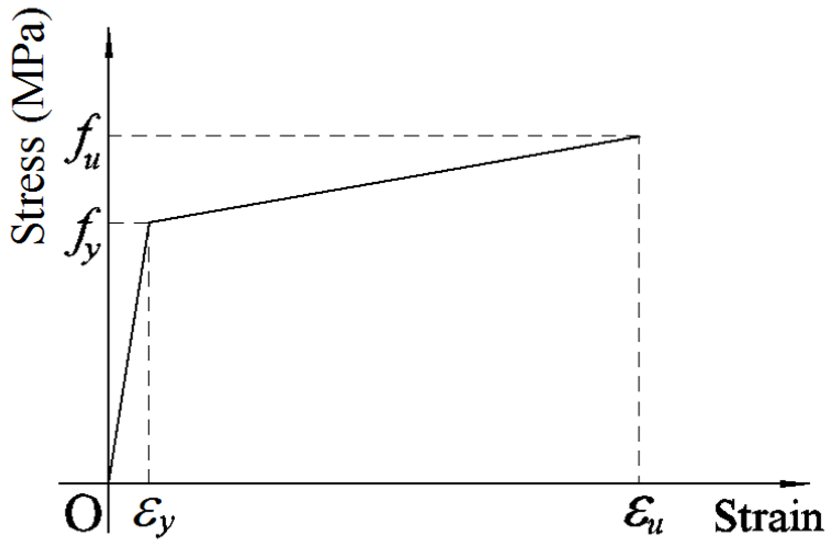
A bilinear stress-strain model of steel, which was employed in Eurocode 2 [48] and used by several researchers [12,36], was selected for use in this paper. This stress-strain model is presented in Figure 1. The elastic modulus was taken as Es = 2 × 10⁵ MPa if the modulus of material was not measured. Otherwise, the measured modulus was used. Similarly, the yield and ultimate strengths of steel were used if these strengths were obtained from tests. If limited test information was provided, the ultimate strength fu was determined by Equation (1) or Equation (2) [49] and the ultimate strain was taken as εu = 0.025 as recommended by Eurocode 2 [48].
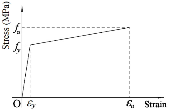
Figure 1.
Bilinear stress-strain model of steel.
3.2. Compressive and Tensile Stress-Strain Model of Concrete
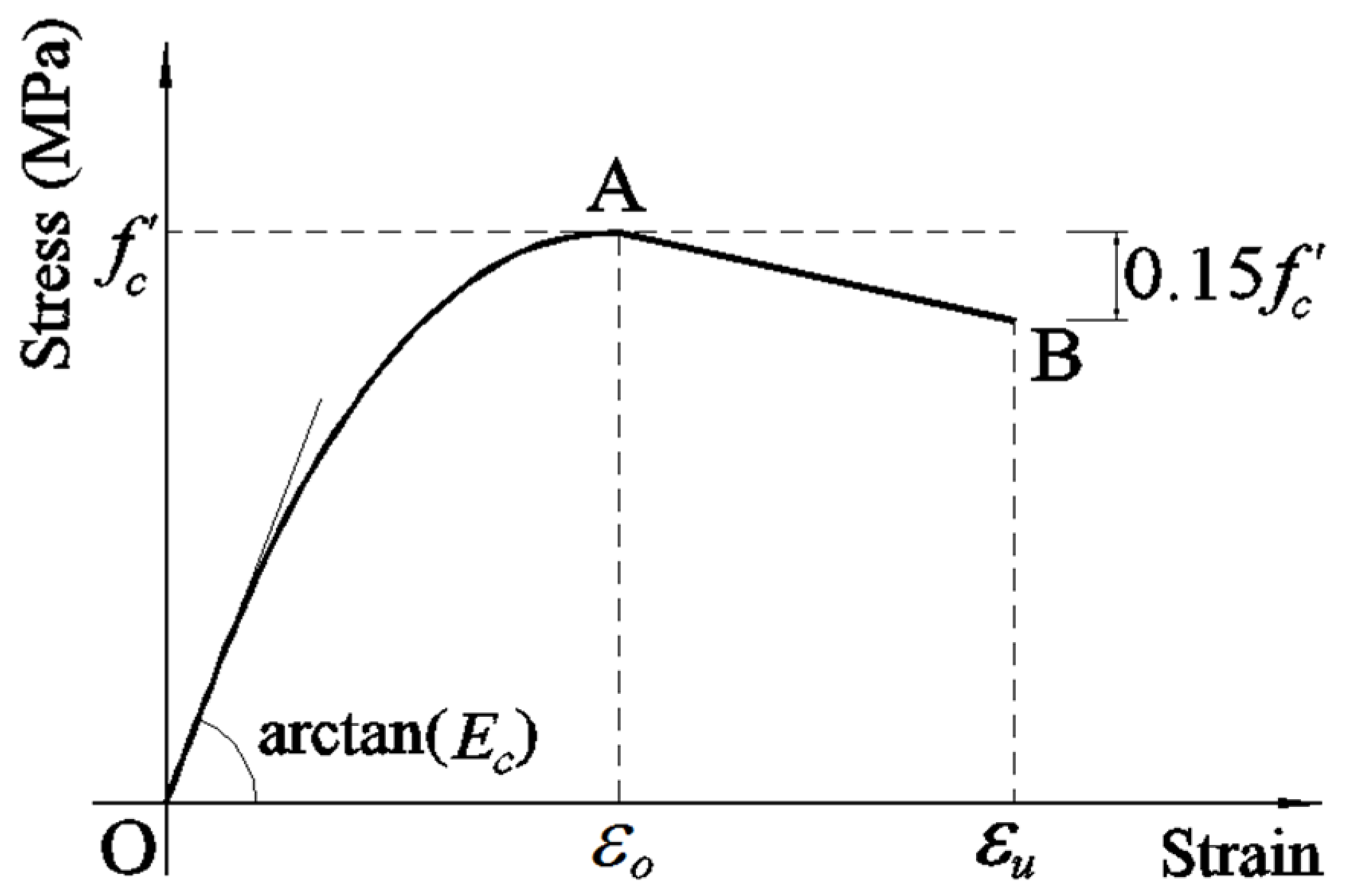
The compressive strength of concrete in CFSTs significantly increases due to the confinement effects of steel tube when CFSTs are subjected to axial compression. However, the confinement effect of steel tubes under torsional moment is a different story, in which it may not significantly increase the compressive strength while it clearly prevents the spalling of concrete. Therefore, the model proposed by Hognestad [50], and shown in Figure 2, which has been widely used to model unconfined concrete under compression, was selected for this study. The stress-strain relationship up to the maximum point is a parabola, expressed by Equation (3), in which, εc is the strain, εo is the strain corresponding to maximum stress computed by Equation (4), f′c is the maximum stress, Ec is the modulus of elasticity and can be taken as [51].

Figure 2.
Hognestad [50] model.
After the maximum point, the stress-strain relationship is linear, expressed by Equation (5). The stress reduces 15% comparing to f′c when the strain εu = 0.0038.
The stress-strain curve of concrete up to f′c/2 is almost linear [52]. Therefore, the plastic part can be taken from f′c/2 to the end of the curve. At the stress f′c/2, the corresponding strain is determined by Equation (6).
4. Modelling
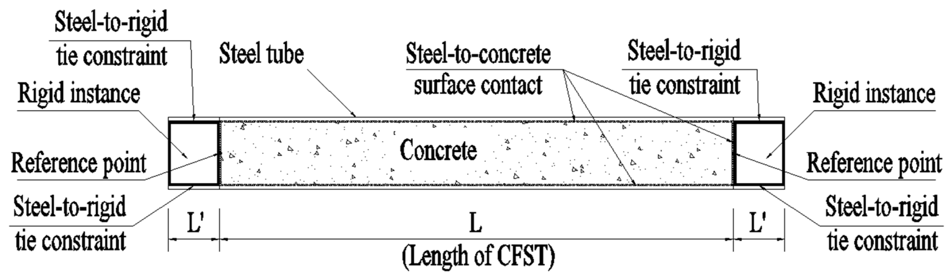
Figure 3 shows the illustration, while Figure 4 presents details the modelling of CFSTs using ABAQUS [47]. Steel tube and infill concrete are the two main components in modelling CFSTs. The additional components are the two steel plates at two ends of CFSTs. To model these two steel plates, Li et al. [12,53] treated these plates as elastic blocks with large modulus materials to convert them into rigid bodies. Ellobody [54], and Le and Fehling [55], directly used rigid bodies for these two steel plates. This technique was adopted with a modification in this study in which the two steel plates were modelled using two rigid cylinder blocks with discrete rigid parts available in ABAQUS [47]. The radius of these rigid blocks was equal to the inner radius of the steel tube. The length of these rigid blocks is L′ and that of CFST is L as shown in Figure 3. The discrete rigid parts were modelled using rigid R3D4 shell elements. The important reason for using the rigid cylinder blocks is that they provide surfaces (one circumferential surface and two sectional surfaces), which are very convenient for modelling “surface-to-surface” contacts. The cylinder blocks are also convenient for applying torsional loading and boundary conditions.
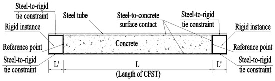
Figure 3.
Illustration of modelling.

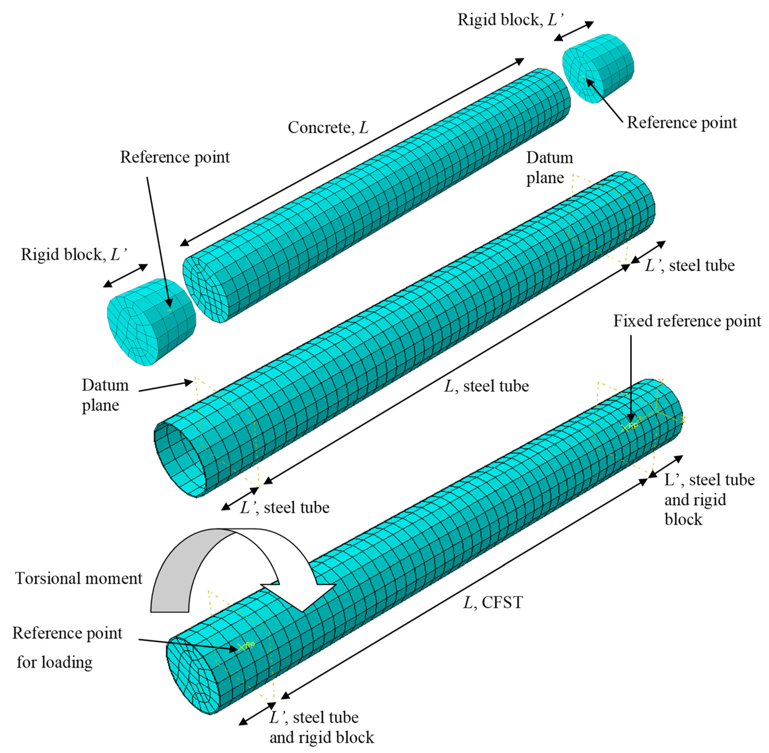
Figure 4.
Details in modelling CFST under torsion.
Tie constraints were used for connection between the circumferential surface of the rigid cylinder blocks and the inner surfaces of steel tubes within the length L′. These are steel-to-rigid tie constraints as shown in Figure 3. “Surface-to-surface” contact was used to model the interaction between surfaces of concrete and steel tube. “Surface-to-surface” contact was also used for modelling the interaction between the rigid blocks and concrete surface at the two ends. These steel-to-concrete contacts are shown in Figure 3. A reference point was assigned for each rigid block. It is worth noting that the reference points were at the center of the sectional rigid-block surface, which was adjacent to the concrete as shown in Figure 3. After assembling instances, the reference points were located at the two ends and on the axial axis of CFST.
The “surface-to-surface” contact in ABAQUS [47], which was used for modelling the interaction between the inner steel tube surface and concrete surface, is described as follows. The surface of infill concrete was modelled as a slave surface while the steel surface was modelled as a master surface. Similar interaction was assigned for the contact between surfaces of the rigid blocks and concrete. The master surface possibly penetrates the slave surface, while the reverse does not occur. The contact between the rigid blocks and steel tube within the length L′ was modelled by ‘tie contact’, in which displacements and rotations of these two surfaces are the same during the loading. ‘Hard contact’ was employed to model the contact between the steel tube and concrete under normal contact, while the ‘penalty’ friction model was used to model the tangent contact. The normal pressure (p) can fully transfer between surfaces. The shear stress is also transferred when it is less than or equal to the limit shear stress τcritical = μp, where μ is the coefficient of friction [35]. After this limit shear stress, the stress on surfaces remains as constant surface stress corresponding to the critical shear stress. The penalty method allows relative motions of surfaces as an elastic slip. The friction coefficient can vary from 0.2 to 0.6, as suggested by Baltay and Gjelsvik [56]. The values 0.25, 0.3, and 0.6 were used by Han et al. [37], Lam et al. [57], and Schneider [58]. The value 0.6 was the most suitable, as reported by Rabbat and Russell [59], and was thus used in this paper.
‘Solid 8-noded reduced integration’ (C3D8R) elements were adopted in this paper to model both steel tubes and concrete. These C3D8R elements were employed by Han et al. [37], Qiu et al. [60], Dai et al. [61], and Espinos et al. [62]. The mesh density was also studied for convergence, relatively accurate results, and appropriately computational time. A fine element size may lead to problems of computational time and numerical convergence, while a coarse mesh size may cause inaccurate results. Thus, an identification of appropriate mesh sizes was conducted to obtain reliable results. The element meshes for steel tubes and concrete are shown in Figure 4.
The boundary conditions and loading were assigned to the reference points. At the initial step of the modelling, one reference point was fixed for all degrees of freedom: U1 = U2 = U3 = 0, UR1 = UR2 = UR3 = 0. The other reference point was fixed for five degrees of freedom: U1 = U2 = U3 = 0, UR1 = UR2 = 0, while the degree of freedom UR3 was set as free. The purpose of this free degree of freedom UR3 was its later use in applying torsional loading. In the analysis step, the rotational moment was applied using rotational displacement control. The rotational displacement, with respect to the free degree of freedom UR3, was compulsorily increased step-by-step; correspondingly, the torsional moment was computed. Previous studies [28,32,37,39] used different target angles of twist in their analyses and experiments. Absolute angles of twist up to about 20° were employed in previous studies [32,37,39]. The strain and deformation of CFSTs depend not only the angle of twist, but also the length of the specimens; therefore, the relative angle of twist (angle of twist per unit length) seems to be more general. Lee et al. [28] used the relative angle of twist 0.4 rad/m in their analytical study. In this study, the target rotation 0.4 rad/m was adopted. When the rotation increased from zero to the assigned angle of twist, the moment-rotation curve was obtained.
5. Verifications
5.1. Moment-Rotation Curve
The numerical models were verified using different results available in the literature. Verification using the test results of CFSTs under pure torsion, as obtained by Beck and Kiyomiya [36], is presented in Section 5.1.1. In Section 5.1.2, the numerical model is compared with the test result obtained by Han and Zhong [63] and the numerical result obtained by Han et al. [37]. Section 5.1.3 presents the verification using the test data obtained by Le et al. [64].
5.1.1. Comparing with the Test Results Obtained by Beck and Kiyomiya
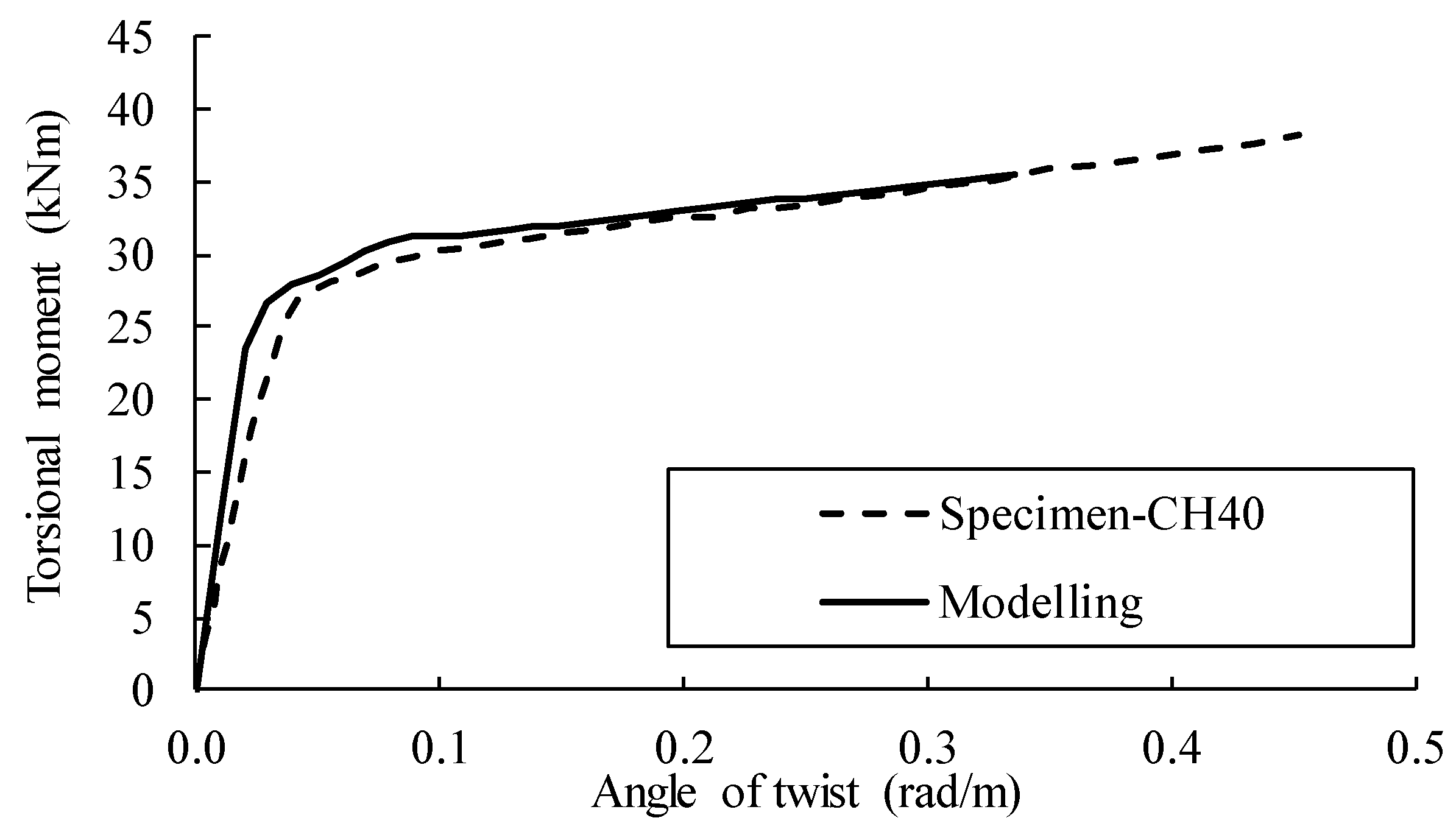
The CFST specimen CH40 tested by Beck and Kiyomiya [36] was selected for verification. The dimensions D × t × L were 139.8 × 4.0 × 1000 (mm). The yield and ultimate steel strengths were 340.3 and 417.0 MPa, respectively. The compressive strength of concrete was 27 MPa. Further details of this specimen can be found in Ref. [36]. The length 150 mm at each end of the CFST specimen CH40 was strengthened using a steel structure, which was used for transferring the torsion moment from the testing machine to the specimen. Therefore, in modelling this specimen, the length of 700 mm was used. Figure 5 compares the numerical results with the experimental result, and there is a good agreement between the two results.
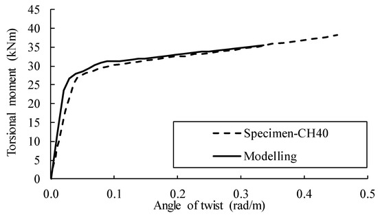
Figure 5.
Numerical vs. experimental (adapted from [36]) results.
5.1.2. Comparing with the Experimental Results Obtained by Han and Zhong
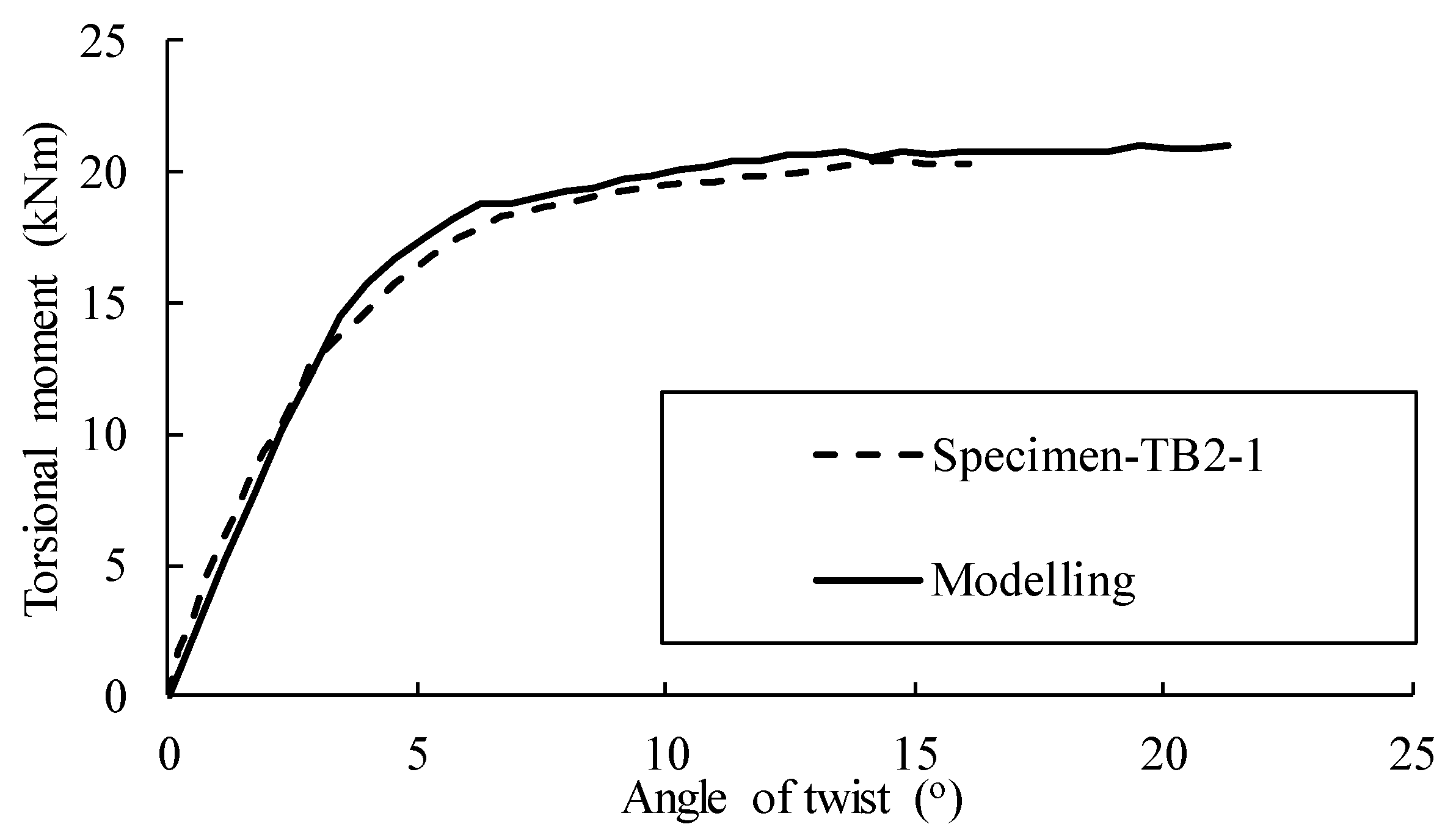
The specimen TB2-1, tested by Han and Zhong [63], was selected to verify the numerical model in ABAQUS [47]. The dimensions D × t × L were 130 × 3.0 × 2000 (mm). The yield strength of steel was 324.34 MPa, while the ultimate strength was not provided. The compressive strength of concrete was 30.4 MPa (cubic samples). Further details of these specimens can be found in Ref. [63]. Because the ultimate strength was not provided, the elastic-perfectly plastic model of steel was used in modeling this specimen. Figure 6 compares the numerical results with the experimental result [63], and a good agreement between the two results can be observed.
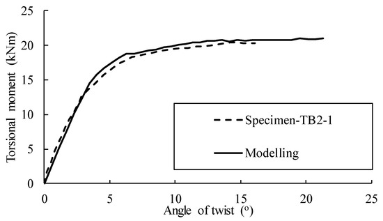
Figure 6.
Comparing the numerical and experimental (adapted from [63]) results.
5.1.3. Comparing with the Experimental Data Obtained by Le et al.
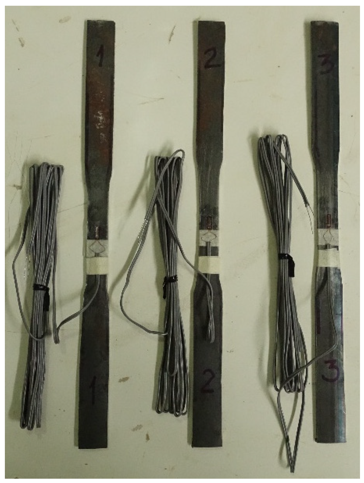
The experimental data obtained by Le et al. [64] was used to verify the numerical models. In these experiments, three coupons of steel were tested to determine the yield and the ultimate strengths. When the CFST specimens were modeled, the elastic modulus is required. This can be taken as 2 × 10⁵ MPa, which is commonly used. However, the authors decided to further conduct coupon tests to obtain the measured modulus, instead of using the widely used value stated above. Three coupon specimens of steel were taken for this purpose. These coupon specimens were fabricated and strain gauges were installed, as shown in Figure 7.
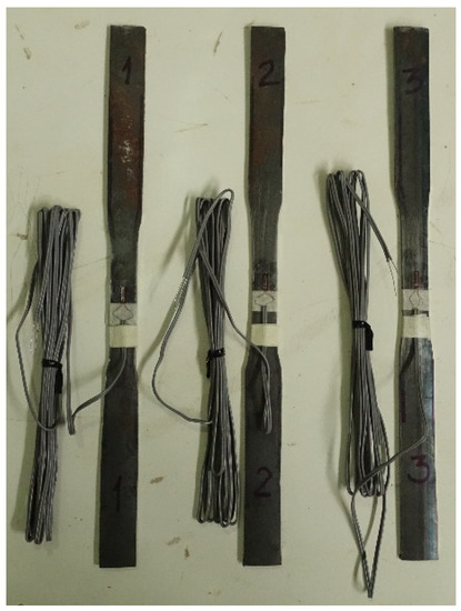
Figure 7.
Specimens with strain gauges for testing the elastic modulus.
The three coupon specimens of steel were tested in the elastic range to determine the elastic modulus. As shown in Figure 7, these specimens were labelled from left to right as ‘1’, ‘2’ and ‘3’, respectively. The measured modulus of specimens ‘1’, ‘2’ and ‘3’ was 188,809, 186,376, and 193,007 MPa, respectively. The average modulus was 189,397 MPa. This modulus is quite close to the commonly used value 2.105 MPa, which is regulated in many design codes. The measured modulus was used for the modelling.
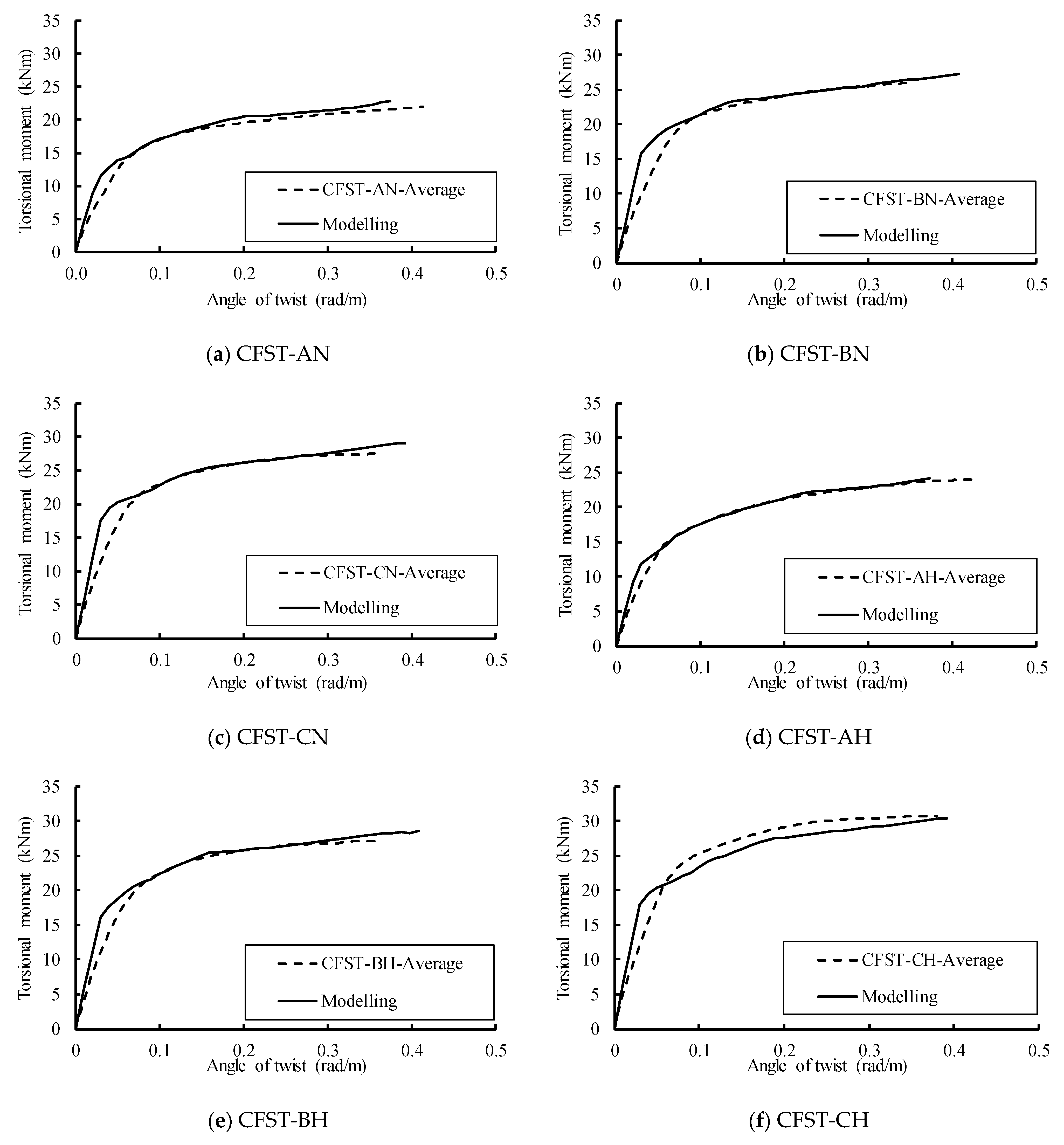
Six CFST specimen groups were used to verify the numerical model. Three thicknesses of 2.3, 3.0, and 3.5 mm were used in the tests. The outer diameter of the steel tube was 140 mm. Thus, the D/t ratios were 60.9, 46.7, and 40.0. The two compressive strengths of the concrete were 24.2 and 33.3 MPa. Details of these specimens are presented in Table 1.

Table 1.
Tested specimens (adapted from [64]).
Figure 8 compares the moment-rotation curves obtained from our modelling and experiments. Overall, good agreements between the two results can be seen in this figure. There was a slight difference, which can be explained by the boundary conditions (such as the bolt connection and the steel plate) in the experiments, which were not taken into account in the modelling as the steel plates at the two ends were modelled as rigid instances.
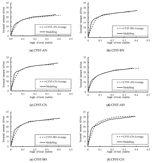
Figure 8.
Comparing the numerical and experimental (adapted from [64]) results.
6. Load Transferring Mechanism
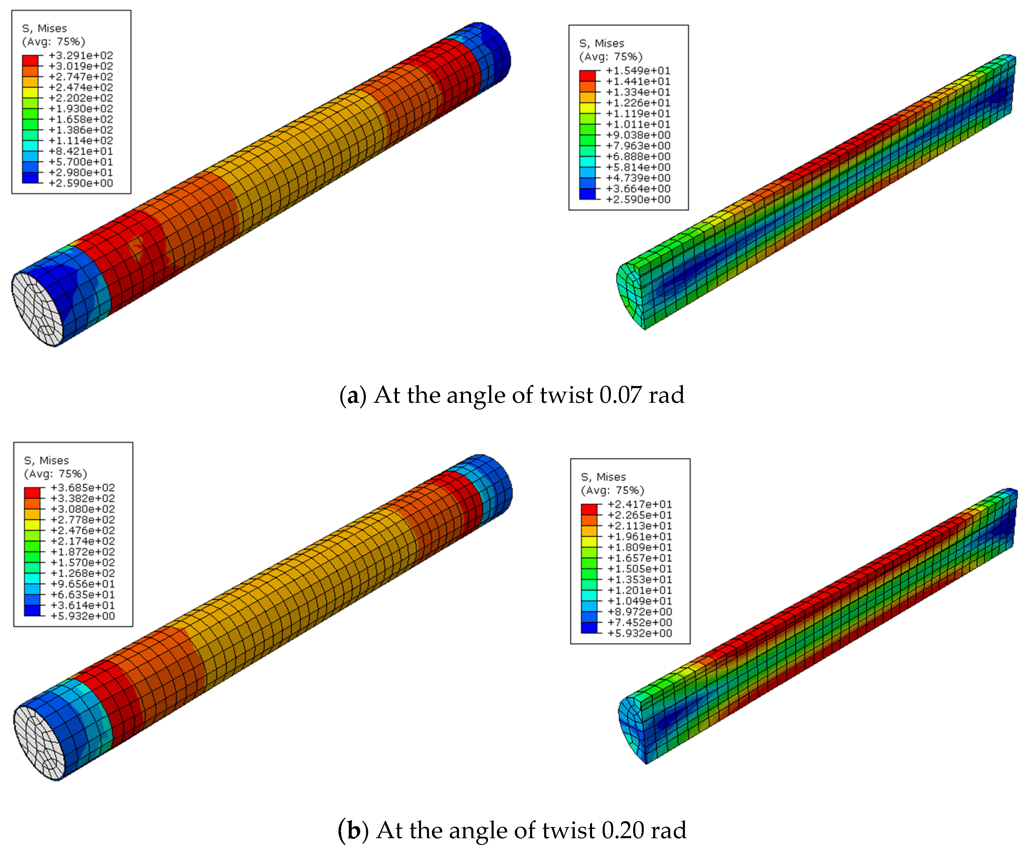
Figure 9a,b show examples of stress variations in steel tube and concrete at the twist angles of 0.07 and 0.20 radians, respectively. In each figure, the left image is the stress of the steel tube while the right image is that of concrete. Along the axial axis, the stress at the two ends of the steel tube was greater than that at the middle region. On the contrary, the stress at the middle region of concrete was higher than that at the two ends. This confirms the non-uniform distribution of stress in steel tube and concrete. Although the total torsional moment is the same for all cross sections of the CFSTs, the moments sustained by the steel tube and concrete vary along the longitudinal axis. Moving from one end to the middle, the moment sustained by steel tube decreases and the moment sustained by the concrete increases.

Figure 9.
Examples of stress distribution in steel tube and concrete (unit is in MPa).
A load transferring mechanism can be observed from Figure 9 as follows. The moment acting on the steel plates (modelled by the rigid blocks) was transferred to steel tube and concrete. The steel tube was welded to the steel plate; therefore, the steel plate (rigid block) and steel tube have the same rotation, which was modelled by the tie constraint in ABAQUS. On the contrary, the connecting between the steel plate (rigid block) and the concrete sectional surface was ‘surface-to-surface’, not ‘welded’. This connection depended only on the friction between surfaces of the steel plate and concrete. Therefore, the moment from the steel plate transferring to the concrete depended on the friction noted above. Obviously, compared with the ‘weld’ contraints of steel tube, the moment sustained by the friction was much smaller. This small torsional moment at the two ends of concrete caused small stress at these locations, as observed in Figure 9. Going from the end section to the middle section of the CFST, the area of contact surface increased, leading to an increase of the friction. This provided the condition to transfer the higher torsional moment to the concrete.
7. Parametric Study
After validating the finite element models with a satisfactory agreement between the results obtained from the modelling and experiments, a parametric study was conducted using the validated models. The effects of the parameters on the torsional strengths of CFSTs were analyzed. The studied parameters included the yield shear strength of steel τy, the compressive strength of concrete f′c, the D/t ratio and the confinement factor ξ. It should be noted that, when under pure shear torsion, the yield shear strength of steel τy is equal to the tensile strength fy. The results of the parametric study are presented in each subsection.
7.1. Effect of Yield Strength of Steel on the Torsional Behaviour of CFSTs
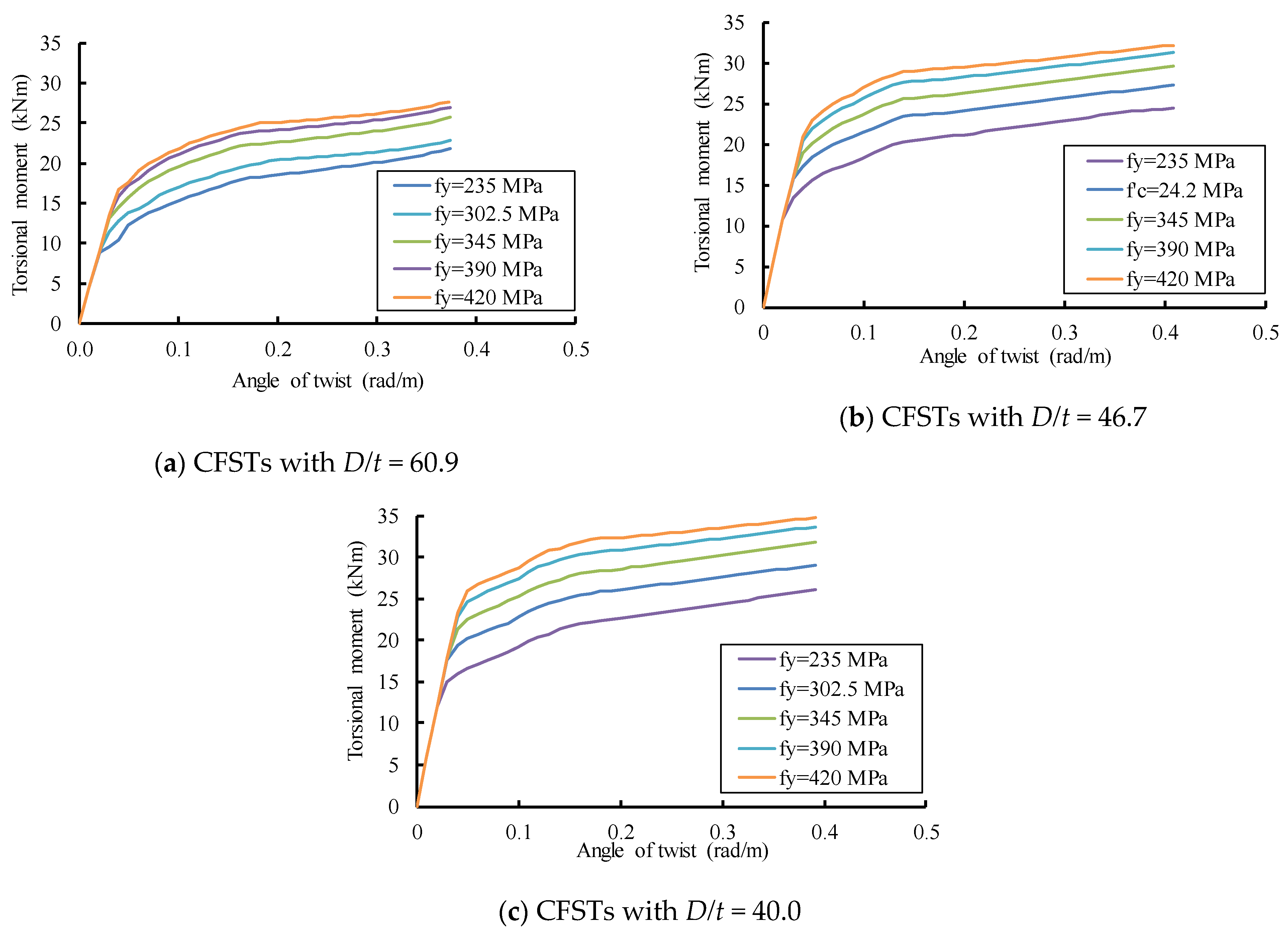
Four yield steel strengths of 235, 345, 390 and 420 MPa, which were used by Nie et al. [44], were also used in this study. Figure 10 shows the effects of the yield steel strength on the behavior of CFSTs. As Figure 10 illustrates, the elastic branches are almost identical up to the point where the curves deviate from their linearity. The un-change of elastic stiffness was attributed to the fact that the increase of yield strength fy had a marginal influence on the elastic modulus. The yield moment of the CFSTs significantly increased as the yield strength of steel increased. The yield steel strength exhibited important impacts on the plastic behavior of the CFSTs. For the same concrete strength of 24.2 MPa, when the yield steel strength increased from 235 MPa to 420 MPa, the yield moment of CFSTs with D/t ratios of 60.9, 46.7, and 40.0 increased by 51.6%, 50.6% and 56.6%, respectively. This increase of the yield moment can be approximated by 1.5 times.
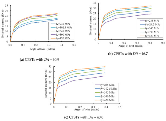
Figure 10.
Effect of yield strength of steel on the torsional behavior of CFSTs with different D/t ratios.
7.2. Effect of Concrete Strength on the Torsional Behavior of CFSTs
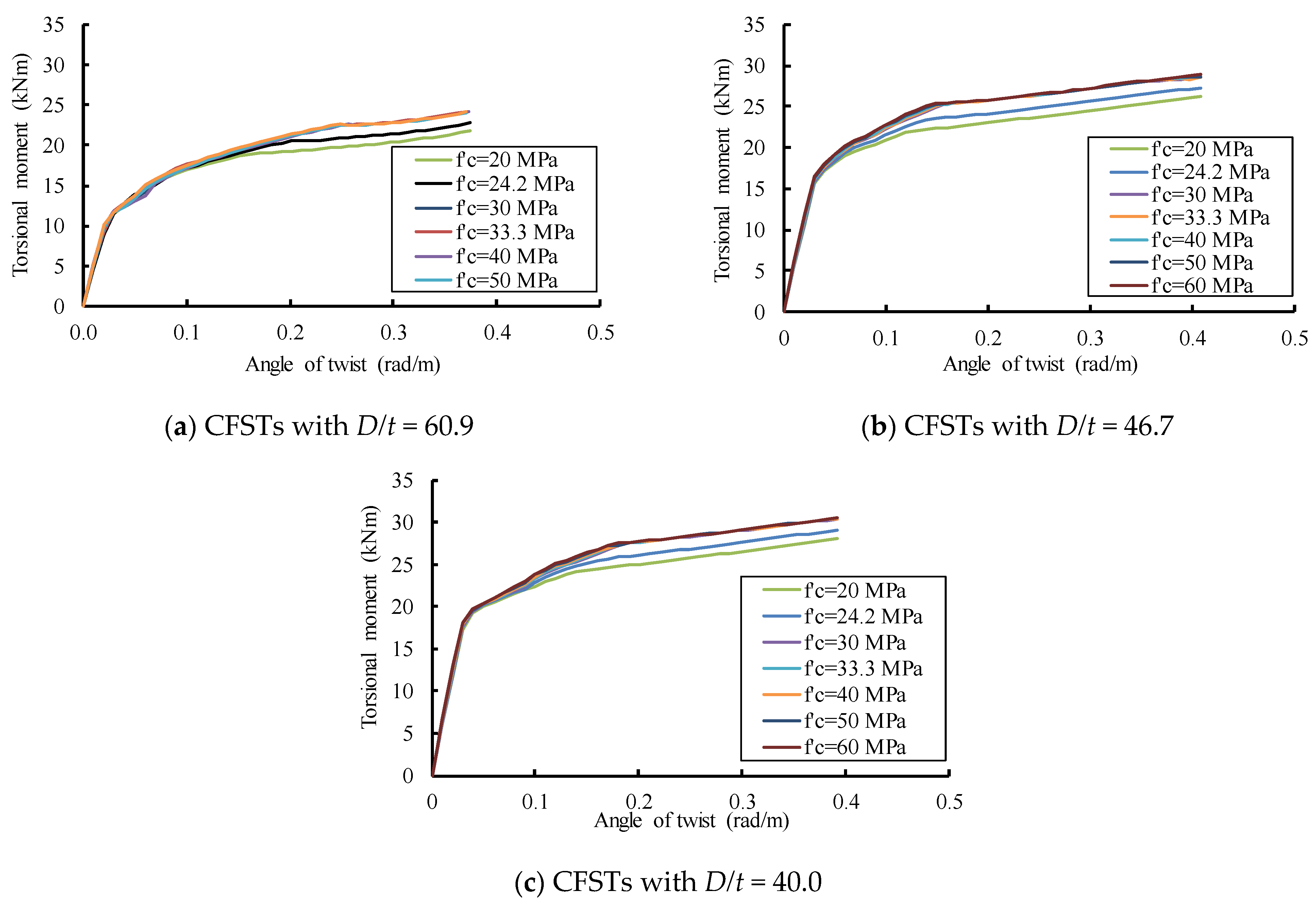
The compressive strengths of concrete f’c 20, 30, 40, 50, and 60 MPa were used in the modeling. Figure 11 shows the effect of concrete strength on the torsional behavior of CFSTs with different D/t ratios. It can be observed that the concrete strength does not exhibit any influence on the behavior up to the yield and the early plastic stage. The concrete strength had a marginal effect on the latter plastic stage. The ultimate torsional moment of CFSTs increased by only 10% when the concrete strength increased from 20 MPa to 60 MPa. The concrete strength had slight influence on the ultimate torsional capacity of the CFSTs. This can be explained by the fact that the moment sustained by the concrete relies on the friction between the contact surfaces of the steel tube and concrete. The main function of concrete is to prevent buckling for steel tube, helping steel tube to work effectively. For the same yield strength of steel, when the concrete strength increased from 20 MPa to 60 MPa, the yield moment of the CFSTs with D/t ratios of 60.9, 46.7, and 40.0 marginally increased by 3.6%, 11.2 and 6.5%, respectively.
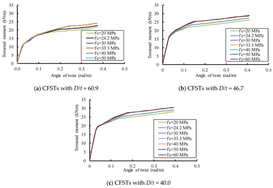
Figure 11.
Effect of concrete strength on the torsional behavior of CFSTs with different D/t ratios.
7.3. Analyses of the Numerical Results
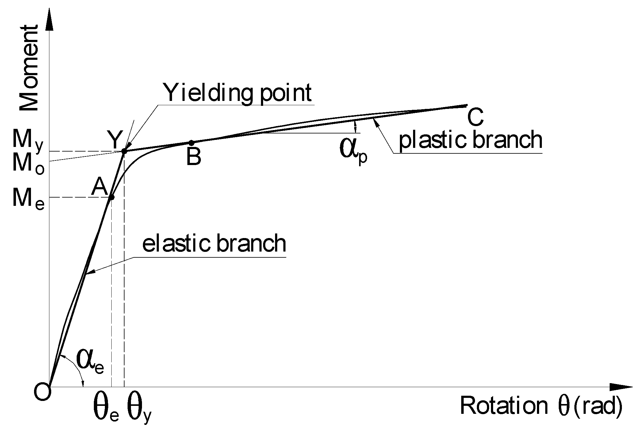
The nominal yielding point can be determined using different methods proposed by Park [65]. Among these methods, the equivalent elastic-plastic yield method was adopted in this study. Because the moment-rotation curves of CFSTs have no obvious descending branches, this method was applied with a modification in which the yielding point Y is the intersection of the elastic branch OA and the plastic branch BC. Each branch can be approximated using a straight line, as illustrated in Figure 12. The slope of the branches OY and YC are the elastic stiffness and plastic stiffness, respectively. The intersection of these two branches can be defined as the nominal yielding point. Equation (7) expresses the elastic branch, while the Equation (8) expresses the plastic branch. In these equations, ke is the elastic stiffness, kp is the plastic stiffness, and Mo is the moment at the intersection of the plastic branch and the vertical axis. At the nominal yielding point (the intersection of the elastic and plastic branches), the right sides of Equations (7) and (8) are equaled to solve for θ, which is then substituted into Equation (7) to obtain the nominal yield moment. This nominal yield moment is expressed by Equation (9).

Figure 12.
Idealized moment-rotation curve.
Table 2 shows the calculation results. In this Table, the torsional inertia modulus Ws of steel tube and the product Wsfy are also computed for correlation analyses in Section 7. In the last column, the increases of My (in percentage) are calculated by comparing them with the first subgroup of the corresponding group. As shown in the last column of Table 2, the yield strength of CFST marginally increased with the increase of concrete strength. As concrete strength increased from 20 MPa to 60 MPa, the nominal yield strength of the CFSTs increased by 3.6%, 11.4%, and 6.5% when the D/t ratios were 60.9, 46.7, and 40.0, respectively. However, when the yield strength of the steel increased from 235 to 420 MPa, the yield torsional moment of CFST increased by 51.6%, 50.6%, and 56.6%, which can be approximated by 50%.
Table 2.
Calculation results.
8. Correlation Analyses
A correlation coefficient [66] was used to analyze the correlation between the mechanical properties and parameters of the CFSTs. It is worth mentioning that the Spearman’s rank correlation was used for two random variables: X(X1, X2, …, Xn) and Y(Y1, Y2,…, Yn), which are in monotonic ranking schemes, while the Pearson’s correlation was used for variables X and Y in random ranking schemes [66,67]. The mechanical properties and parameters of the CFSTs are of random ranking schemes; thus, the Pearson’s correlation was used in this paper. The Pearson’s correlation coefficient [66,67] between variables X and Y is defined by Equation (10), where, and are the means of the variables X and Y.
Figure 13 and Figure 14 show the results of the correlation between the mechanical properties (Me, elastic stiffness, plastic stiffness, My) and parameters of the CFSTs. It is worth noting that some correlation coefficients are negative. For the sake of visual comparison and clarity, their absolute values were used to plot these Figures. Values with the mark (*) in Figure 13 and Figure 14 are originally negative.
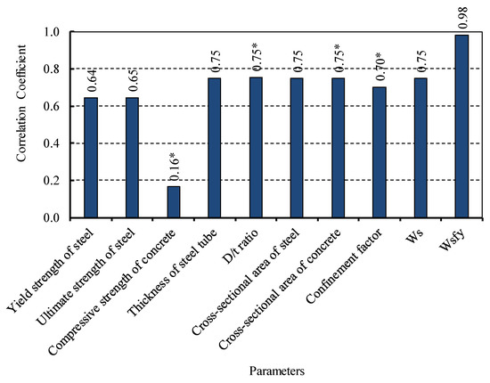
Figure 13.
Correlation between Me and parameters.
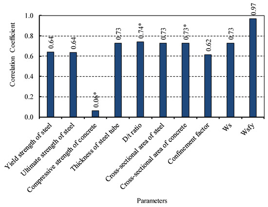
Figure 14.
Correlation between the nominal yield moment My and parameters.
It can be observed in Figure 13 that compressive strength of concrete exhibits a poor correlation; on the contrary, the product Wsfy shows the strongest correlation with the elastic moment. Other parameters have the values of correlation coefficients varied from 0.64 to 0.75. It should be pointed out that these parameters directly or indirectly relate to the steel tube. For example, the cross-sectional area of concrete has the correlation coefficient of 0.75 because it indirectly relates to the cross-sectional area of steel tube. The compressive strength of concrete is the only parameter that is independent with the steel tube; thus, it has the poor correlation with Melastic.
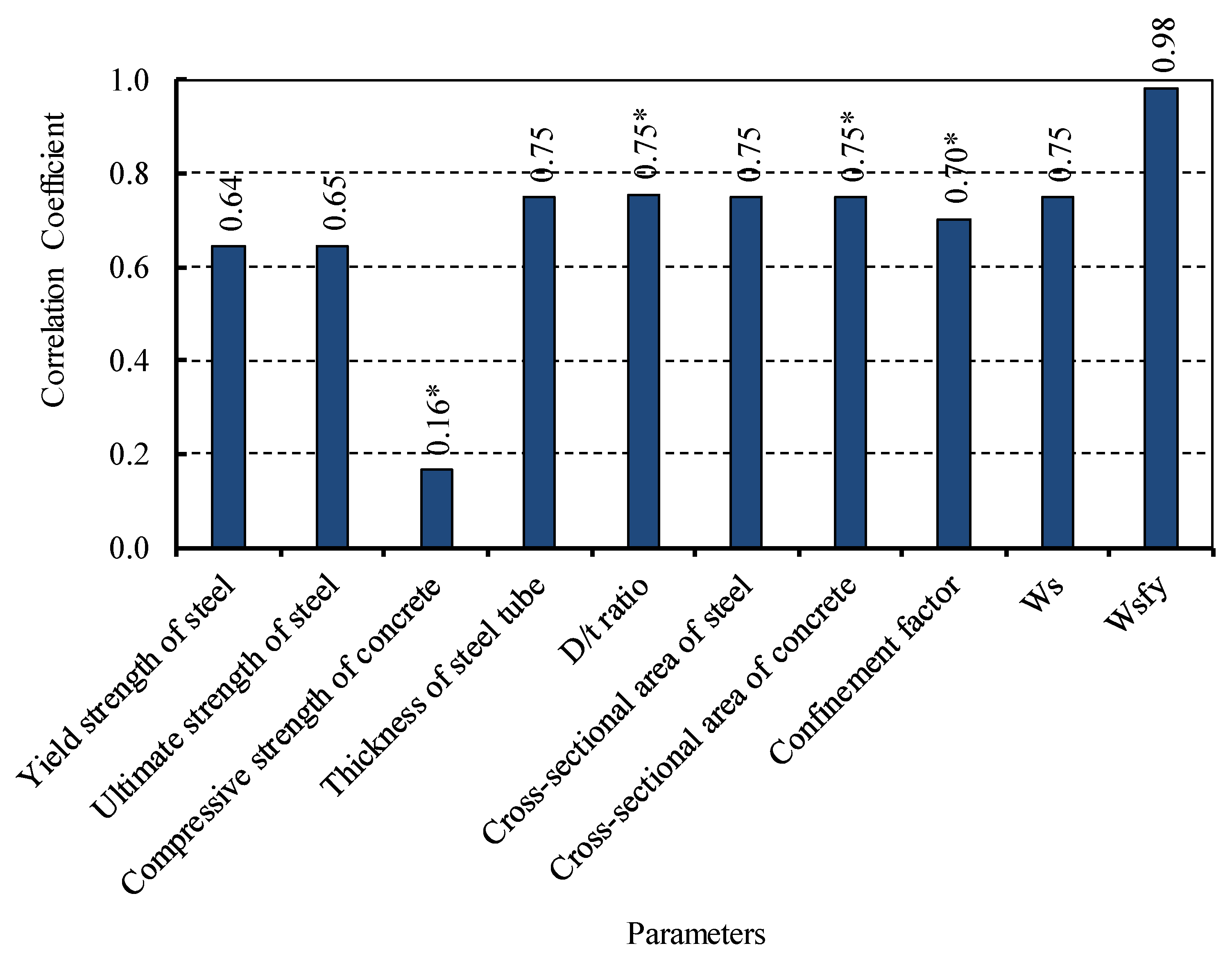
Figure 14 shows the correlation between nominal yield moment My and parameters of the CFSTs. Again, the compressive strength of concrete shows the poorest candidate on the correlation with My. This poor correlation is because My mainly relies on the steel tube, while the concrete plays as a ‘helper’ to make steel tube avoid buckling and work more effectively. The majority of parameters have correlation coefficients that vary from 0.62 to 0.74. Interestingly, although My has a moderate correlation with the torsional modulus of inertia Ws, it shows the best correlation with the product Wsfy. This can be explained by the fact that My depends on not only the sectional property (represented by Ws), but also the mechanical property of steel (represented by fy). Table 3 provides further details on the correlation between My and parameters, in which the correlation coefficients were sorted in a descending order. The best correlation belongs to the product Wsfy, followed by D/t ratio, Ws, the cross sectional areas of steel As, and concrete Ac, while the compressive strength of concrete comes in the last position.
Table 3.
Correlation between the nominal yield moment My and parameters.
9. Conclusions
In this study, numerical models of CFSTs were developed in ABAQUS. The models in ABAQUS were verified by comparing the results obtained from these models with experimental/numerical results available in the literature. After validating, the validated models were used for a parametric study. The main parameters studied included the steel strength, concrete strength, D/t ratio, confinement factor, and parameters related to concrete and steel tube. Conclusions are drawn as follows, which may help engineers when designing CFSTs subjected to torsional moment.
- The distribution of stress exhibited a mechanism of torsional moment transferring. Moving from one end section to the middle section of the CFST, the moment sustained by steel tube decreased while that of concrete increased. The stress of steel at the end regions was greater than that at the middle region. On the contrary, the stress on concrete at the end regions was smaller than that at the middle region.
- Concrete strength marginally affected the moment-rotation behavior of the CFSTs. Improving the behavior and capacity of the CFST was not the main function of concrete, while its main function was to prevent buckling of steel tubes and thus to make steel tubes work more effectively.
- The steel strength did not affect the elastic stiffness; however, it decisively affected the nominal yield strength and the plastic behavior of the CFSTs. When the yield steel strength increased from 235 to 420 MPa, the nominal yield torsional moment of the CFSTs increased by approximately 50%.
- Correlation analyses were performed to see the correlation degree between the mechanical properties and parameters of the CFSTs. The results showed that the parameters related to the steel tube had higher correlation coefficients than those related to concrete. Interestingly, the yield torsional moment of steel tube had the strongest correlation with the nominal yield moments of the CFSTs followed by D/t ratio, while the compressive strength of concrete came in the last position.
Author Contributions
K.B.L.: Conceptualization, Methodology, Formal analysis, Writing—Original draft preparation, Project administration, Funding acquisition, Supervision. V.V.C.: Resources, Investigation, Validation, Data curation, Formal analysis, Visualization, Writing—Reviewing and Editing. All authors have read and agreed to the published version of the manuscript.
Funding
This research is funded by Vietnam National University HoChiMinh City (VNU-HCM) under grant number B2020-20-05.
Institutional Review Board Statement
Not applicable.
Informed Consent Statement
Not applicable.
Data Availability Statement
Data is contained within the article.
Conflicts of Interest
The authors state that there is no conflict of interest.
Abbreviations
| D | diameter of steel tube |
| t | thickness of steel tube |
| L | length of CFST |
| L′ | length of rigid blocks |
| Es | elastic modulus of steel |
| fy | yield strength of steel |
| fu | ultimate strength of steel |
| εy | yield strain of steel |
| εu | ultimate strain of steel |
| εc | strain of concrete |
| εo | strain corresponding to maximum stress of concrete |
| f′c | maximum stress of concrete |
| Ec | elastic modulus of concrete |
| μ | coefficient of friction |
| p | normal pressure |
| ξ | confinement factor |
| τy | yield shear strength of steel |
| ke | elastic stiffness |
| kp | plastic stiffness |
| Mo | moment at the intersection of the plastic branch and the vertical axis |
| θ | rotation |
| Ws | torsional inertia modulus of cross section of steel tube |
| As | cross sectional area of steel tube |
| Ac | cross sectional area of concrete |
| Me | elastic moment |
| My | yield moment |
| X, Y | variables |
| , | means of the variables X and Y |
References
- Dundu, M. Compressive strength of circular concrete filled steel tube columns. Thin-Walled Struct. 2012, 56, 62–70. [Google Scholar] [CrossRef]
- Xu, L.; Zhou, P.; Chi, Y.; Huang, L.; Ye, J.; Yu, M. Performance of the high-strength self-stressing and self-compacting concrete-filled steel tube columns subjected to the uniaxial compression. Int. J. Civ. Eng. 2017, 16, 1069–1083. [Google Scholar] [CrossRef] [Green Version]
- Van Cao, V. Experimental Behaviour of recycled aggregate concrete-filled steel tubes under axial loading. Int. J. Civ. Eng. 2019, 17, 1341–1351. [Google Scholar] [CrossRef]
- Tao, Z.; Uy, B.; Han, L.-H.; Wang, Z.-B. Analysis and design of concrete-filled stiffened thin-walled steel tubular columns under axial compression. Thin-Walled Struct. 2009, 47, 1544–1556. [Google Scholar] [CrossRef]
- Han, L.-H.; He, S.-H.; Liao, F.-Y. Performance and calculations of concrete filled steel tubes (CFST) under axial tension. J. Constr. Steel Res. 2011, 67, 1699–1709. [Google Scholar] [CrossRef]
- Chen, J.; Wang, J.; Li, W. Experimental behaviour of reinforced concrete-filled steel tubes under eccentric tension. J. Constr. Steel Res. 2017, 136, 91–100. [Google Scholar] [CrossRef]
- Van Cao, V.; Le, Q.D.; Nguyen, P.T. Experimental behaviour of concrete-filled steel tubes under cyclic axial compression. Adv. Struct. Eng. 2019, 23, 74–88. [Google Scholar] [CrossRef]
- Elchalakani, M.; Zhao, X.-L.; Grzebieta, R. Concrete-filled steel circular tubes subjected to constant amplitude cyclic pure bending. Eng. Struct. 2004, 26, 2125–2135. [Google Scholar] [CrossRef]
- Han, L.-H.; Hou, C.; Zhao, X.-L.; Rasmussen, K.J.R. Behaviour of high-strength concrete filled steel tubes under transverse impact loading. J. Constr. Steel Res. 2014, 92, 25–39. [Google Scholar] [CrossRef]
- Du, G.; Babic, M.; Wu, F.; Zeng, X.; Bie, X.-M. Experimental and numerical studies on concrete filled circular steel tubular (cfcst) members under impact loads. Int. J. Civ. Eng. 2019, 17, 1211–1226. [Google Scholar] [CrossRef]
- Dey, P.; Gupta, R.K.; Laskar, A.I. Numerical and Experimental Investigations of Different Cross-Sectional Configuration of Plain Concrete and CFST Short Columns under Axial Compression. Int. J. Civ. Eng. 2019, 17, 1585–1601. [Google Scholar] [CrossRef]
- Li, G.; Chen, B.; Yang, Z.; Feng, Y. Experimental and numerical behaviour of eccentrically loaded high strength concrete filled high strength square steel tube stub columns. Thin-Walled Struct. 2018, 127, 483–499. [Google Scholar] [CrossRef]
- Skalomenos, K.; Hayashi, K.; Nishi, R.; Inamasu, H.; Nakashima, M. Experimental Behavior of Concrete-Filled Steel Tube Columns Using Ultrahigh-Strength Steel. J. Struct. Eng. 2016, 142, 04016057. [Google Scholar] [CrossRef]
- Lam, D.; Gardner, L.; Burdett, M. Behaviour of axially loaded concrete filled stainless steel elliptical stub columns. Adv. Struct. Eng. 2010, 13, 493–500. [Google Scholar] [CrossRef]
- Tao, Z.; Uy, B.; Liao, F.-Y.; Han, L.-H. Nonlinear analysis of concrete-filled square stainless steel stub columns under axial compression. J. Constr. Steel Res. 2011, 67, 1719–1732. [Google Scholar] [CrossRef]
- Xiang, X.; Cai, C.; Zhao, R.; Peng, H. Numerical analysis of recycled aggregate concrete-filled steel tube stub columns. Adv. Struct. Eng. 2016, 19, 717–729. [Google Scholar] [CrossRef]
- Yang, Y.-F.; Han, L.-H.; Zhu, L.-T. Experimental performance of recycled aggregate concrete-filled circular steel tubular columns subjected to cyclic flexural loadings. Adv. Struct. Eng. 2009, 12, 183–194. [Google Scholar] [CrossRef]
- Ren, Q.-X.; Zhou, K.; Hou, C.; Tao, Z.; Han, L.-H. Dune sand concrete-filled steel tubular (CFST) stub columns under axial compression: Experiments. Thin-Walled Struct. 2018, 124, 291–302. [Google Scholar] [CrossRef]
- Ostrowski, K.; Dudek, M.; Sadowski, Ł. Compressive behaviour of concrete-filled carbon fiber-reinforced polymer steel composite tube columns made of high performance concrete. Compos. Struct. 2020, 234, 111668. [Google Scholar] [CrossRef]
- Yu, Q.; Tao, Z.; Wu, Y.-X. Experimental behaviour of high performance concrete-filled steel tubular columns. Thin-Walled Struct. 2008, 46, 362–370. [Google Scholar] [CrossRef]
- Elremaily, A.; Azizinamini, A. Behavior and strength of circular concrete-filled tube columns. J. Constr. Steel Res. 2002, 58, 1567–1591. [Google Scholar] [CrossRef]
- Alatshan, F.; Osman, S.A.; Hamid, R.; Mashiri, F. Stiffened concrete-filled steel tubes: A systematic review. Thin-Walled Struct. 2020, 148, 106590. [Google Scholar] [CrossRef]
- Ansari, M.; Jeddi, M.; Badaruzzaman, W.; Tahir, M.; Osman, S.; Hosseinpour, E. A numerical investigation on the through rib stiffener beam to concrete-filled steel tube column connections subjected to cyclic loading. Eng. Sci. Technol. Int. J. 2020, 24, 728–735. [Google Scholar] [CrossRef]
- Han, L.-H.; Wang, W.-H.; Yu, H.-X. Experimental behaviour of reinforced concrete (RC) beam to concrete-filled steel tubular (CFST) column frames subjected to ISO-834 standard fire. Eng. Struct. 2010, 32, 3130–3144. [Google Scholar] [CrossRef]
- Han, L.-H.; Wang, W.-H.; Yu, H.-X. Analytical behaviour of RC beam to CFST column frames subjected to fire. Eng. Struct. 2012, 36, 394–410. [Google Scholar] [CrossRef]
- Nie, J.-G.; Wang, Y.-H.; Fan, J.-S. Experimental study on seismic behavior of concrete filled steel tube columns under pure torsion and compression–torsion cyclic load. J. Constr. Steel Res. 2012, 79, 115–126. [Google Scholar] [CrossRef]
- Nie, J.-G.; Wang, Y.-H.; Fan, J.-S. Experimental research on concrete filled steel tube columns under combined compression-bending-torsion cyclic load. Thin-Walled Struct. 2013, 67, 1–14. [Google Scholar] [CrossRef]
- Lee, E.-T.; Yun, B.H.; Shim, H.J.; Chang, K.H.; Lee, G.C. Torsional behavior of concrete-filled circular steel tube columns. J. Struct. Eng. 2009, 135, 1250–1258. [Google Scholar] [CrossRef]
- Wang, Y.-H.; Nie, J.-G.; Fan, J.-S. Fiber beam-column element for circular concrete filled steel tube under axial–flexure–torsion combined load. J. Constr. Steel Res. 2014, 95, 10–21. [Google Scholar] [CrossRef]
- Xin, N.; Yu-Hang, W.; Shuo, L.; Ju, C. Coupled bending-shear-torsion bearing capacity of concrete filled steel tube short columns. Thin-Walled Struct. 2018, 123, 305–316. [Google Scholar] [CrossRef]
- Han, L.-H.; Yao, G.-H.; Tao, Z. Behaviors of concrete-filled steel tubular members subjected to combined loading. Thin-Walled Struct. 2007, 45, 600–619. [Google Scholar] [CrossRef]
- Wang, Y.-H.; Wang, W.; Chen, J. Seismic behavior of steel tube confined RC columns under compression-bending-torsion combined load. J. Constr. Steel Res. 2018, 143, 83–96. [Google Scholar] [CrossRef]
- Wang, P.; Han, Q.; Du, X. Seismic performance of circular RC bridge columns with flexure–torsion interaction. Soil Dyn. Earthq. Eng. 2014, 66, 13–30. [Google Scholar] [CrossRef]
- Ren, Q.-X.; Han, L.-H.; Hou, C.; Tao, Z.; Li, S. Concrete-encased CFST columns under combined compression and torsion: Experimental investigation. J. Constr. Steel Res. 2017, 138, 729–741. [Google Scholar] [CrossRef]
- Wang, Y.-H.; Zhou, X.-H.; Deng, R.; Lan, Y.-S.; Luo, W.; Li, P.; Yang, Q.-S.; Ke, K. Coupled ultimate capacity of CFRP confined concrete-filled steel tube columns under compression-bending-torsion load. Structures 2021, 31, 558–575. [Google Scholar] [CrossRef]
- Beck, J.; Kiyomiya, O. Fundemental pure torsional properties of concrete filled circular steel tubes. Doboku Gakkai Ronbunshu 2003, 60, 285–296. [Google Scholar] [CrossRef] [Green Version]
- Han, L.-H.; Yao, G.-H.; Tao, Z. Performance of concrete-filled thin-walled steel tubes under pure torsion. Thin-Walled Struct. 2007, 45, 24–36. [Google Scholar] [CrossRef]
- Wang, Y.-H.; Guo, Y.-F.; Liu, J.-P.; Zhou, X.-H. Experimental study on torsion behavior of concrete filled steel tube columns subjected to eccentric compression. J. Constr. Steel Res. 2017, 129, 119–128. [Google Scholar] [CrossRef]
- Wang, Y.-H.; Lu, G.-B.; Zhou, X.-H. Experimental study of the cyclic behavior of concrete-filled double skin steel tube columns subjected to pure torsion. Thin-Walled Struct. 2018, 122, 425–438. [Google Scholar] [CrossRef]
- Ding, F.-X.; Sheng, S.-J.; Yu, Y.-J.; Yu, Z.-W. Mechanical behaviors of concrete-filled rectangular steel tubular under pure torsion. Steel Compos. Struct. 2019, 31, 291–301. [Google Scholar] [CrossRef]
- Ding, F.-X.; Fu, Q.; Wen, B.; Zhou, Q.-S.; Liu, X.-M. Behavior of circular concrete-filled steel tubular columns under pure torsion. Steel Compos. Struct. 2018, 26, 501–511. [Google Scholar] [CrossRef]
- Chen, J.; Jin, W.L.; Fu, J. Experimental investigation of thin-walled centrifugal concrete-filled steel tubes under torsion. Thin-Walled Struct. 2008, 46, 1087–1093. [Google Scholar] [CrossRef]
- Chen, J.; Chen, J.; Jin, W.L. Design of thin-walled centrifugal concrete-filled steel tubes under torsion. Thin-Walled Struct. 2009, 47, 271–276. [Google Scholar] [CrossRef]
- Nie, X.; Wang, W.; Wang, Y.-H.; Yu, J.; Hou, C. Ultimate torsional capacity of steel tube confined reinforced concrete columns. J. Constr. Steel Res. 2019, 160, 207–222. [Google Scholar] [CrossRef]
- Majed, M.M.; Tavakkolizadeh, M.; Allawi, A.A. Finite element analysis of rectangular RC beams strengthened with FRP laminates under pure torsion. Struct. Concr. 2021. [Google Scholar] [CrossRef]
- Onge, J.S.; Fam, A. Torsional Behavior of Circular Concrete-Filled FRP Tubes. J. Compos. Constr. 2021, 25, 04021013. [Google Scholar] [CrossRef]
- Smith, M. ABAQUS/Standard User’s Manual; Dassault Systèmes Simulia Corp: Providence, RI, USA, 2017. [Google Scholar]
- CEN. Eurocode 2: Design of Concrete Structures-Part 1-1: General Rules and Rules for Buildings; European Committee for Standardization: Brussels, Belgium, 2004. [Google Scholar]
- Tao, Z.; Wang, Z.-B.; Yu, Q. Finite element modelling of concrete-filled steel stub columns under axial compression. J. Constr. Steel Res. 2013, 89, 121–131. [Google Scholar] [CrossRef]
- Hognestad, E. A Study of Combined Bending Axial Load in Reinforced Concrete Members; Bulletin Series, No. 399; Engineering Experimental Station, The University of Illinois: Urbana, IL, USA, 1951; Volume 49. [Google Scholar]
- ACI. Building Code Requirements for Structural Concrete (ACI 318M-08) and Commentary; American Concrete Institute: Farmington Hills, MI, USA, 2008. [Google Scholar]
- Park, R.; Paulay, T. (Eds.) Reinforced Concrete Structures; John Wiley & Sons: New York, NY, USA; London, UK; Sydney, Australia; Toronto, ON, Canada, 1975. [Google Scholar]
- Li, S.; Han, L.-H.; Hou, C. Concrete-encased CFST columns under combined compression and torsion: Analytical behaviour. J. Constr. Steel Res. 2018, 144, 236–252. [Google Scholar] [CrossRef]
- Ellobody, E. Numerical modelling of fibre reinforced concrete-filled stainless steel tubular columns. Thin-Walled Struct. 2013, 63, 1–12. [Google Scholar] [CrossRef]
- Le Hoang, A.; Fehling, E. Numerical study of circular steel tube confined concrete (STCC) stub columns. J. Constr. Steel Res. 2017, 136, 238–255. [Google Scholar] [CrossRef]
- Baltay, P.; Gjelsvik, A. Coefficient of friction for steel on concrete at high normal stress. J. Mater. Civ. Eng. 1990, 2, 46–49. [Google Scholar] [CrossRef]
- Lam, D.; Dai, X.; Han, L.-H.; Ren, Q.-X.; Li, W. Behaviour of inclined, tapered and STS square CFST stub columns subjected to axial load. Thin-Walled Struct. 2012, 54, 94–105. [Google Scholar] [CrossRef]
- Schneider, S.P. Axially loaded concrete-filled steel tubes. J. Struct. Eng. 1998, 124, 1125–1138. [Google Scholar] [CrossRef]
- Rabbat, B.G.; Russell, H.G. Friction coefficient of steel on concrete or grout. J. Struct. Eng. 1985, 111, 505–515. [Google Scholar] [CrossRef]
- Qiu, W.; McCann, F.; Espinos, A.; Romero, M.; Gardner, L. Numerical analysis and design of slender concrete-filled elliptical hollow section columns and beam-columns. Eng. Struct. 2017, 131, 90–100. [Google Scholar] [CrossRef]
- Dai, X.; Lam, D.; Jamaluddin, N.; Ye, J. Numerical analysis of slender elliptical concrete filled columns under axial compression. Thin-Walled Struct. 2014, 77, 26–35. [Google Scholar] [CrossRef]
- Espinos, A.; Romero, M.L.; Hospitaler, A. Advanced model for predicting the fire response of concrete filled tubular columns. J. Constr. Steel Res. 2010, 66, 1030–1046. [Google Scholar] [CrossRef]
- Han, L.; Zhong, S. The studies of pure torsion problem for concrete filled steel tube. Ind. Constr. 1995, 92, 562–573. [Google Scholar]
- Le, K.B.; Van Cao, V.; Cao, H.X. Circular concrete filled thin-walled steel tubes under pure torsion: Experiments. Thin-Walled Struct. 2021, 164, 107874. [Google Scholar] [CrossRef]
- Park, R. Ductility evaluation from laboratory and analytical testing. In Proceedings of the 9th World Conference on Earthquake Engineering, Tokyo, Japan, 2–9 August 1988. [Google Scholar]
- Spiegel, M.R. (Ed.) Theory and Problems of Statistics; McGraw-Hil: London, UK, 1990. [Google Scholar]
- Jones, M.C.; Gibbons, J.D.; Chakraborti, S. Nonparametric statistical inference. J. R. Stat. Soc. Ser. A Stat. Soc. 1993, 156, 503. [Google Scholar] [CrossRef]

Publisher’s Note: MDPI stays neutral with regard to jurisdictional claims in published maps and institutional affiliations. |
© 2021 by the authors. Licensee MDPI, Basel, Switzerland. This article is an open access article distributed under the terms and conditions of the Creative Commons Attribution (CC BY) license (https://creativecommons.org/licenses/by/4.0/).