Article

Seismic Performance Analysis of Tuned Mass Rocking Wall (TMRW)-Frame Building Structures

College of Civil Engineering, Fuzhou University, Fuzhou 350108, China
*
Author to whom correspondence should be addressed.
Buildings 2021, 11(7), 293; https://doi.org/10.3390/buildings11070293
Submission received: 4 June 2021 / Revised: 27 June 2021 / Accepted: 29 June 2021 / Published: 5 July 2021
(This article belongs to the Special Issue Seismic Performance of New-Designed and Existing RC Buildings)

Abstract

:
A tuned mass rocking wall (TMRW) is a passive control device that combines the merits of a traditional tuned mass damper (TMD) and a traditional rocking wall (RW). TMRWs not only help avoid weak story failure of the host structure but can also be regarded as a largely tuned mass substructure in the building structure. Through the appropriate design of the frequency ratio, the host structure can dissipate much more energy under earthquake excitations. In this paper, the basic equations of motion for the mechanical model of an SDOF structure-rigid rocking wall are established, and the optimization formulas of frequency ratio and damping ratio of TMRW are derived. Through the dynamic elastoplastic analysis of a six-story TMRW-frame model, the applicability of the derived parameter optimization formulas and the effectiveness of the TMRW in seismic performance control are investigated. The results demonstrate that the TMRW can coordinate the uneven displacement angle between stories of the host structure. Additionally, the TMRW is found to possess the merit of reducing both the peak and root-mean-square (RMS) structural responses when subjected to different types of earthquake excitations.

1. Introduction

Concrete frame structures can collapse due to yield failure from earthquake excitation [1]. Ductile design can improve the seismic performance of the structure, but it may also increase interstory drifts [2]. In order to realize the ideal damage mechanism of a frame structure, the RW, as a whole key component, has attracted the attention of many scholars. The RW relies on its own sufficient lateral bearing capacity and stiffness to control the lateral deformation mode of the host structure. The resulting change in stress of the original frame structure improves the overall seismic performance of the structure [3]. In order to introduce members that can effectively control the lateral deformation mode, Ajrab et al. [4] first proposed the concept of RW-frame structure in combination with the advantage of an unbonded, prestressed concrete self-resetting shear wall; that is, the weak story failure of the frame structure can be avoided through the lateral force resistance advantage of RW. Qu and Ye [5] investigated the damage mechanism of RW-frame structural systems through nonlinear dynamic analysis and then proposed a method to determine the stiffness of RW according to the stiffness demand of RW. Guo et al. [6] investigated the seismic performance of RW-frame structures by pushover analysis. The results show that the RW can significantly increase the overall bearing capacity of the structure, with a more consistent distribution of displacement among stories along with a more uniform plastic hinge distribution. Makris and Aghagholizad [7] analyzed the control results of the stepping rocking wall coupled with an SDOF oscillator and verified the superiority of suppressing displacement response for more flexible structures.
However, the RW has poor elastoplastic energy dissipation. Thus, many scholars use the relatively uniform deformation mode created by RW to arrange energy dissipation elements between the wall and the frame column or between the wall and the foundation. Qu [8] and Qu et al. [9] proposed an energy dissipation mechanism of setting shear dampers along the height of RW. The G3 Building of the Tokyo Institute of Technology in Japan is an example of such an approach. Compared with the other common building structures, the G3 Building shows remarkable seismic performance and has an exceptional ability to reduce the seismic responses of the structure. Based on the damage concentration mode, Feng et al. [10] proposed strengthening the RW with buckling-restrained braces (BRB) so that the RW can control the deformation mode and the BRB can provide lateral stiffness and hysteretic damping, which can give full play to the seismic capacity of each part of the structure. Chen et al. [11,12] proposed a rocking structure with a displacement damper set at the bottom of the rocking steel truss to improve the seismic performance of the structure. Zhang and Li [13] further analyzed the control performance of the RW-frame structure with buckling-restrained columns (BRC) and verified that adding BRC at the bottom of the RW can further improve the seismic performance of the RW-frame structure. Collini et al. [14] analyzed the control performance of the passive tuned pendulum connected with a rocking block under excitation of the base, which provides a theoretical basis for the application of real rocking structures.
Most of the existing research regarding RW has focused on the stiffness coordination function of the RW. Most of the energy dissipation elements described in the literature are related to vibration control and are attached between the host structure and the RW or between the RW and the foundation. Prior research efforts neglect the fact that the RW can be designed as a tuned mass substructure. Di Egidio et al. [15] proposed a rigid rocking block that functioned as the TMD. When coupled with the frame structure, this control device was found to possess the merit of reducing both the displacement of the first floor and the drift of the top floor.
In this paper, the energy dissipation capacity of RW is leveraged, and a new type of TMRW-frame system is proposed. The basic equations of motion for the controlled structure are established through the mechanical model of SDOF structure-rigid rocking wall, and the calculation method of frequency ratio and connection stiffness between the RW and the host structure is determined. Using ANSYS, the finite element models of the frame, RW-frame, and TMRW-frame structures are established, and dynamic elastoplastic analysis is carried out. The applicability of the designed formulas of TMRW and the superiority of seismic performance are verified according to the structural responses under earthquake excitations.

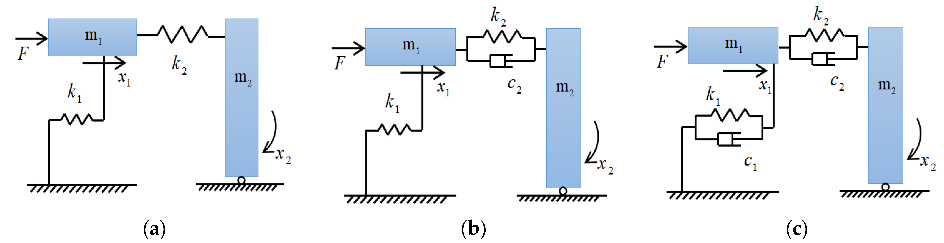
2. Propose of SDOF Structure-Rigid Rocking Wall Model

Referring to Figure 1, TMD is a passive damping device that transfers vibration energy from the main mass to a substructure through the passive resonance of the substructure. Unlike the TMD system, TMRW is placed on the right side of the main mass and hinged to the base. The mechanical model of the SDOF structure-rigid rocking wall is shown in Figure 2a. Considering the large stiffness of the RW in the actual structure, the TMRW is regarded as rigid here. An appropriate frequency ratio design will enable the RW to absorb the vibration energy of the main mass in the reciprocating rocking process, and the energy dissipation principle of the RW is like that of a giant TMD substructure.

2.1. Vibration Analysis of TMRW-1

Referring to Figure 2a, the equations of motion for an SDOF structure-TMRW mechanism are given as
m 1 x ¨ 1 ( t ) + ( k 1 + k 2 ) x 1 ( t ) k 2 h x 2 ( t ) = F ( t )
I 2 x ¨ 2 ( t ) k 2 h x 1 ( t ) + k 2 h 2 x 2 ( t ) = 0
where h is the height of the main mass; I 2 is the moment of inertia of the TMRW, and can be expressed as
I 2 = m 2 h 2 3
During harmonic loading,
F ( t ) = F 0 sin ( ω t )
is applied to m 1 the following expressions for x 1 ( t ) and x 2 ( t ) can be assumed
x 1 ( t ) = X 1 sin ( ω t )
x 2 ( t ) = X 2 sin ( ω t )
Substituting Equations (5) and (6) into Equations (1) and (2), we can derive the steady-state solution
X 1 = ( k 2 h 2 I 2 ω 2 ) F 0 ( k 1 + k 2 m 1 ω 2 ) ( k 2 h 2 I 2 ω 2 ) ( k 2 h ) 2
X 2 = k 2 h F 0 ( k 1 + k 2 m 1 ω 2 ) ( k 2 h 2 I 2 ω 2 ) ( k 2 h ) 2
In order to make the amplitude of the main mass zero, the molecular part of Equation (7) should be equal to zero, so there is
ω 2 = k 2 h 2 I 2
when ω is equal to the natural frequency ω n of the main mass, the expression for calculating stiffness k 2 can be given as
k 2 = m 2 ω n 2 3

2.2. Vibration Analysis of TMRW-2

Referring to Figure 2b, the equations of motion for this model are
m 1 x ¨ 1 ( t ) + c 2 x ˙ 1 ( t ) c 2 h x ˙ 2 ( t ) + ( k 1 + k 2 ) x 1 ( t ) k 2 h x 2 ( t ) = F 0 sin ( ω t )
I 2 x ¨ 2 ( t ) c 2 h x ˙ 1 ( t ) + c 2 h 2 x ˙ 2 ( t ) k 2 h x 1 ( t ) + k 2 h 2 x 2 ( t ) = 0
The equations of a harmonic response analysis are obtained by representing the response in terms of harmonic components with angular frequency ω
x 1 ( t ) = X 1 e i ( ω t + θ 1 )
x 2 ( t ) = X 2 e i ( ω t + θ 2 )
Substituting Equations (13) and (14) into Equations (11) and (12) gives
X 1 e i θ 1 = ( k 2 h 2 I 2 ω 2 + i c 2 ω h 2 ) F 0 [ ( k 1 m 1 ω 2 ) ( k 2 h 2 I 2 ω 2 ) I 2 k 2 ω 2 ] + i c 2 ω ( k 1 h 2 m 1 ω 2 h 2 I 2 ω 2 )
X 2 e i θ 2 = ( k 2 h + i c 2 ω h ) X 1 e i θ 1 k 2 h 2 I 2 ω 2 + i c 2 ω h 2
For brevity, we introduce the following symbols
μ = m 2 m 1 ω n 2 = k 1 m 1 ω d 2 = k 2 h 2 I 2 ζ d = c 2 h 2 2 I 2 ω d
f = ω d ω n g = ω ω n δ st = F 0 k 1
In terms of these parameters, the complex amplitude Equation (15) takes the form
X 1 δ st = { ( 2 ζ d g ) 2 + ( g 2 f 2 ) 2 ( 2 ζ d g ) 2 ( g 2 1 + 1 3 μ g 2 ) 2 + [ 1 3 μ g 2 f 2 ( g 2 1 ) ( g 2 f 2 ) ] 2 } 1 2
The dynamic amplification factor X 1 / δ st is shown as a function of frequency in Figure 3. It is a remarkable fact that all curves intersect at points A and B, for which the magnitude of the response is independent of the damping ratio. Substituting ζ d = 0 and ζ d = into Equation (19) respectively, and setting them equal, we can derive the following equation
g 4 2 [ 3 + ( μ + 3 ) f 2 ] μ + 6 g 2 + 6 f 2 μ + 6 = 0
The roots of Equation (20) are denoted g A 2 and g B 2 and correspond to the fixed points in Figure 3. The ordinates of the two fixed points can be obtained by substituting g A and g B into Equation (19), respectively. When the two ordinates are equal, the control result of the TMRW is optimal. This leads to
f o p t = 3 μ + 3
The optimal value of ζ d should make the dynamic amplification factor of the two fixed points reach the maximum. Substituting Equation (21) into Equation (19) and differentiating g , we can obtain the slope of the curve. By making the slope of point A equal to the slope of point B, the damping ratio is determined as
ζ d 1 2 = 9 μ ( 3 μ μ + 6 ) 8 ( μ + 3 ) 3
ζ d 2 2 = 9 μ ( 3 + μ μ + 6 ) 8 ( μ + 3 ) 3
Since the difference between the two values is small, the average value is taken as the optimal damping ratio
ζ d opt 2 = 27 μ 8 ( μ + 3 ) 3
Using the values of f opt and ζ d opt , the optimal values of stiffness and damping coefficient can be calculated as
k opt = m 2 f opt 2 ω n 2 3
c opt = 2 m 2 ω n ζ d opt f opt 3
The dynamic amplification factors of the uncontrolled and controlled models for μ = 0.5 are illustrated in Figure 4.

2.3. Vibration Analysis of TMRW-3

Referring to Figure 2c, the equations of motion for this model are
m 1 x ¨ 1 ( t ) + ( c 1 + c 2 ) x ˙ 1 ( t ) c 2 h x ˙ 2 ( t ) + ( k 1 + k 2 ) x 1 ( t ) k 2 h x 2 ( t ) = F 0 sin ( ω t )
I 2 x ¨ 2 ( t ) c 2 h x ˙ 1 ( t ) + c 2 h 2 x ˙ 2 ( t ) k 2 h x 1 ( t ) + k 2 h 2 x 2 ( t ) = 0
For brevity, we introduce an extra symbol
ζ s = c 1 2 m 1 ω n
In terms of the parameters above, the dynamic amplification factor of the main mass takes the form
X 1 δ st = { ( 2 ζ d g ) 2 + ( g 2 f 2 ) 2 g 2 [ 2 ζ d ( g 2 1 + 1 3 μ g 2 ) + 2 ζ s ( g 2 f 2 ) ] 2 + [ 1 3 μ g 2 f 2 + 4 ζ s ζ d g 2 ( g 2 1 ) ( g 2 f 2 ) ] 2 } 1 2
Since the values of each parameter have an impact on the dynamic amplification factor in the above Equations, the two fixed points no longer exist. In this case, numerical methods can be adopted to determine f opt and ζ d opt .

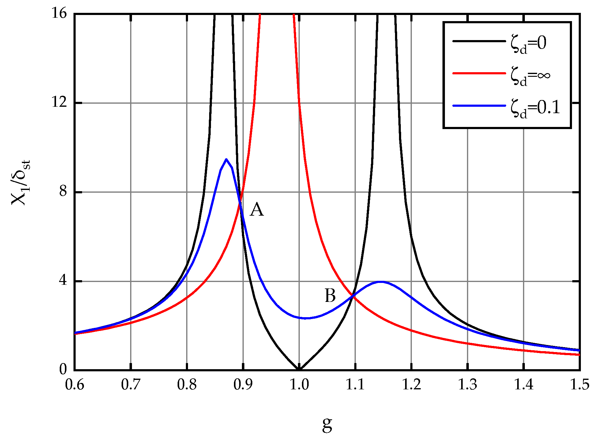
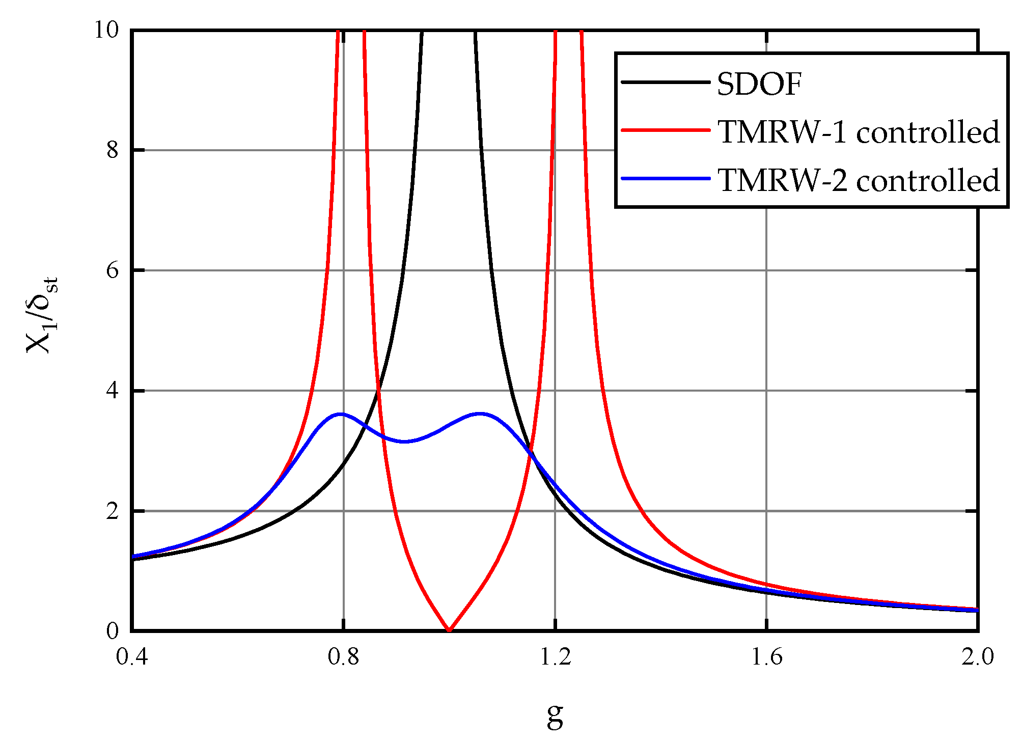
2.4. Control Result of TMRW
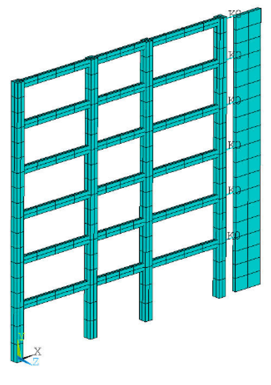
The control performance of TMRW for μ = 0.5 is investigated through the time-history analysis of an SDOF model with ζ s = 0.05 . Sinusoidal base excitation is adopted to excite the model, and the frequency is set as 1 Hz, which is close to the natural frequency of the SDOF model. The amplitude of the excitation is set as 0.1 g. Figure 5 compares the uncontrolled and controlled displacement responses of the main mass. It can be seen from Figure 4 and Figure 5 that the TMRW device is effective when it is designed close to the excitation frequency. In addition, if some damping is added to TMRW, the performance deterioration caused by the change of excitation frequency can be improved.

3. Structure Models

In this paper, the 6-story structure is a typical prototype model that is simplified from a practical frame structure. As shown in Figure 6, a plane finite element model of the TMRW-frame structure is built using ANSYS. The concrete columns are rigidly connected with the foundation. The hinged wall and the frame at each floor level are connected by horizontal connections. The host structure is a six-story reinforced concrete frame with a floor height of 3.6 m and a standard floor height of 3 m. The structure model has three spans, with a side span of 6 m and a middle span of 4.5 m. TMRW is 3 m wide, and the mass ratio between the added mass to the host structure is 0.4. The strength grade of concrete is C30, and HRB335 is adopted as the main reinforcement.
The beams and columns of the reinforced concrete frame are simulated by the three-dimensional linear finite strain beam element Beam188. The elastoplastic constitutive model is simplified into a piecewise linear function by using the constitutive model of reinforced concrete equivalent material proposed by Pian et al. [16]. The elastoplastic constitutive model of the frame column is shown in Figure 7. Elastic shell elements Shell181 are adopted for the RW. The horizontal connection between TMRW and frame is realized by the spring-damper element Combin14. Combin14 has longitudinal or torsional capability in single-dimensional or multi-dimensional applications. The element is defined by a spring-constant, damping coefficients, and two nodes. Stiffness and damping values are designed according to Equations (25) and (26), and the distribution form of each value on the floors is an inverted triangle. El Centro, Taft, and Wenchuan earthquake records are selected with a peak acceleration set between 0.1 g and 0.2 g. Figure 8 shows the acceleration response spectra of earthquake waves when the damping ratio reaches 5%. The corresponding natural frequencies of different structural models are also indicated in Figure 8.

4. Seismic Behavior Analysis of TMRW

4.1. Deformation Mode

In order to assess the seismic behavior of multistory frame structures, the interstory drift ratio (IDR) is frequently used as a measure of damage [7]. Figure 9, Figure 10 and Figure 11 respectively plot the IDRs of the frame, RW-frame, and TMRW-frame structures when different earthquakes strike. The results show that the original frame structure, uncontrolled with RW or TMRW, experiences extremely large IDRs in certain stories under various earthquake excitations while the IDRs of the RW-frame structure are uniformly distributed along each floor without obvious deformation concentration. When the RW is designed to also function as a TMRW, the distribution of IDRs over the height of the host structure can also be improved; but compared with the traditional RW, the ability to coordinate the deformation of the host structure is reduced.

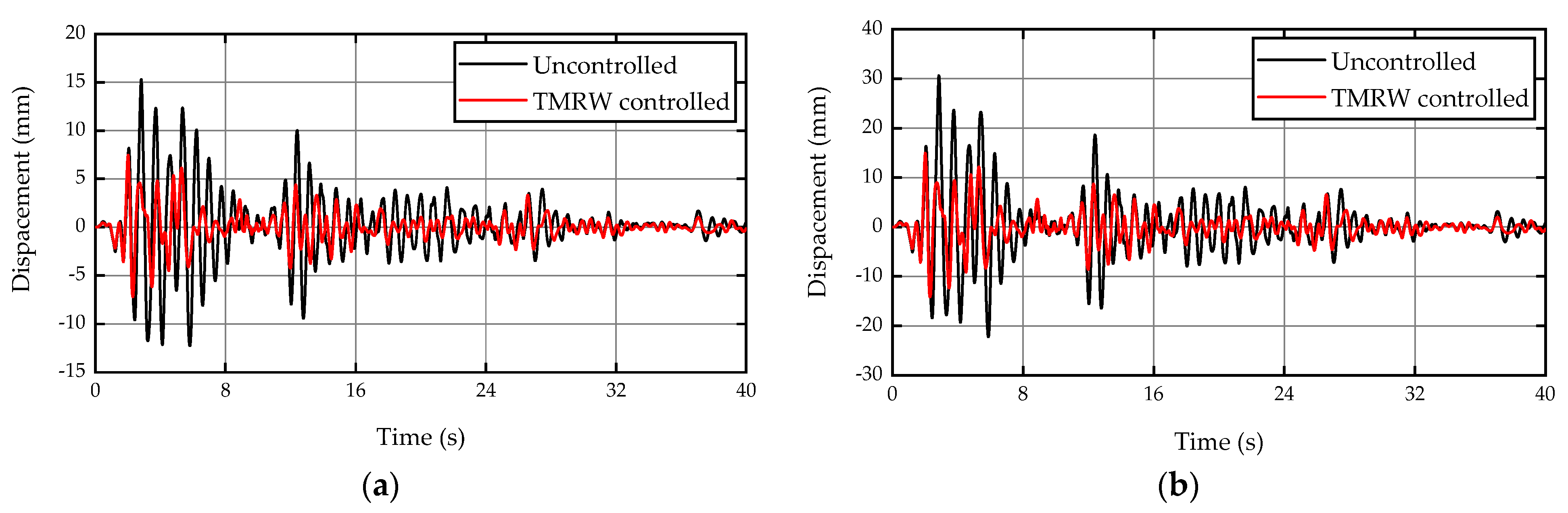
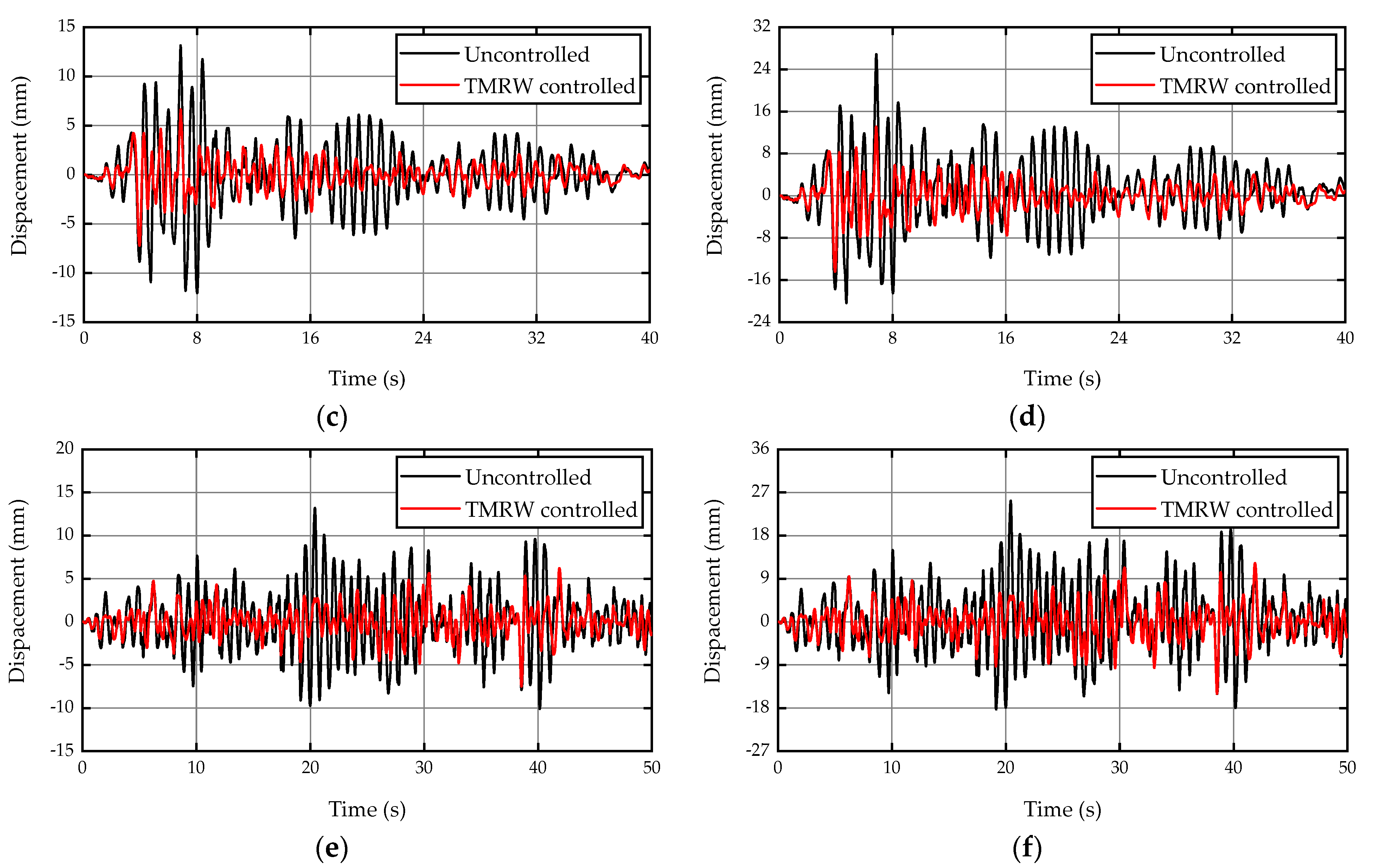
4.2. Displacement and Acceleration Responses

In order to evaluate the control performance of the TMRW, the control effectiveness η was defined as a quantitative index. The control effectiveness is expressed as
η = R u R c R u × 100 %
where R u and R c refer to the uncontrolled and controlled responses, respectively.
Figure 12 shows the control results obtained from different earthquakes, and the displacement responses of the weak layer are compared. Table 1 further compares the peak and the RMS control effectiveness. The control results show that the displacement responses of the weak layer of the host structure are significantly reduced after the TMRW is added. In addition, the control effectiveness on both the peak and the RMS responses is above 40%. When the excitation intensity reaches 0.2 g, the control effectiveness can increase or decrease slightly, but in the worst case is reduced by 4.6%.
Figure 13 compares the acceleration responses at the top of the frame for different earthquake excitations. Table 2 further compares the peak and the RMS control effectiveness. It is observed that the control effectiveness of the RMS responses is above 24.6% after the TMRW is added, and the peak responses are below 21.6%. As the excitation intensity increases from 0.1 g to 0.2 g, the control effectiveness of the peak and the RMS responses reduce by 9.4% and 6.7%, respectively.

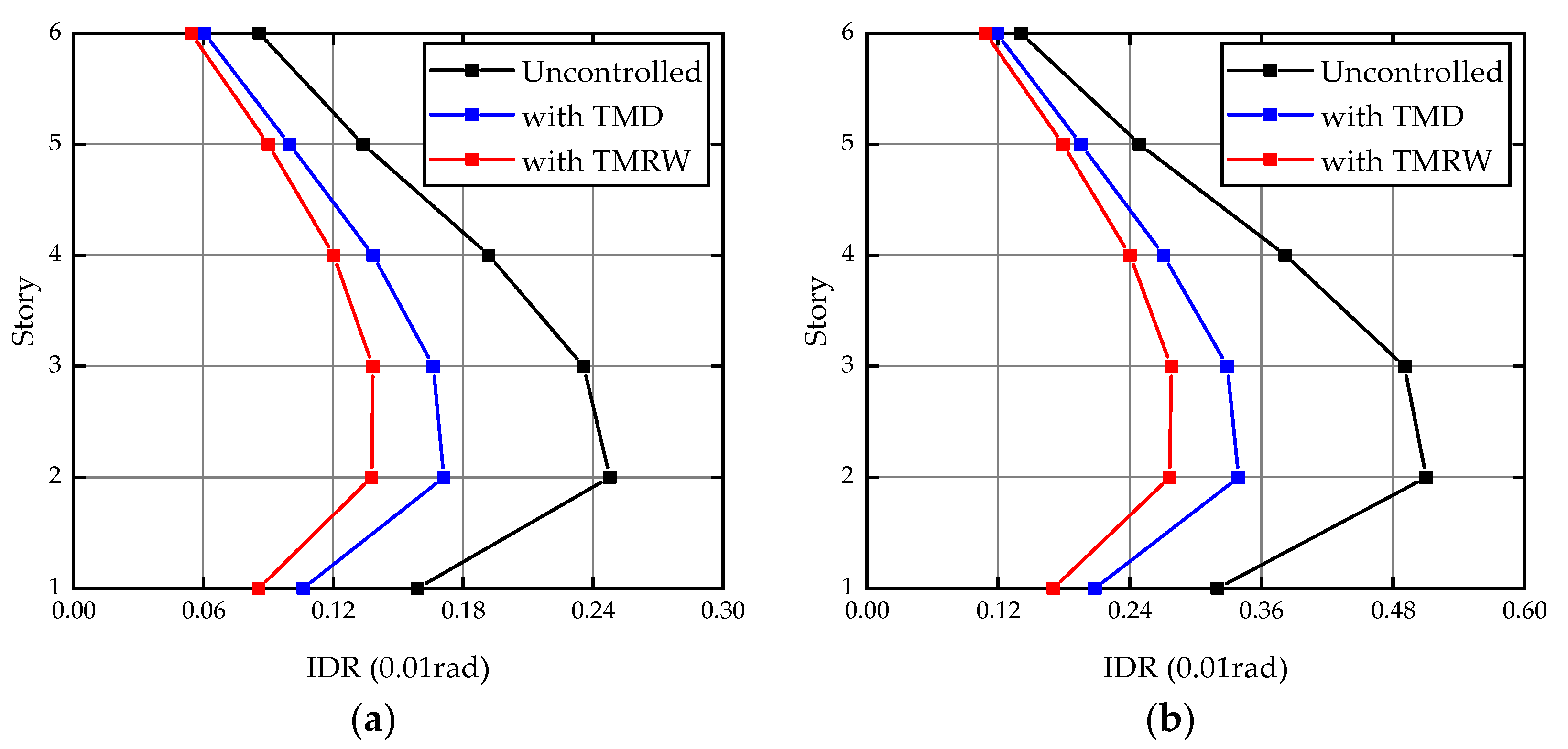
4.3. Comparisons of the Control Results of the TMD and TMRW Controlled Systems

In order to further verify the applicability of the TMRW design formulas for the new structural system, the seismic behavior of the RW designed using the traditional TMD parameter optimization formulas proposed by Rana and Soong [17] is investigated. The distributions of IDRs over the height of the host structure, when subjected to Taft earthquake excitation, are shown in Figure 14. The figures show that the TMRW controlled system has a better reduction on IDRs. Table 3 further compares the control results of uncontrolled, TMD, and TMRW controlled systems. One can see that from the table, under Taft excitation, the two controlled systems have a good seismic performance on both the peak and the RMS responses. However, compared to TMRWs, TMDs have poorer control effectiveness in each case.

5. Conclusions

In this paper, a new type of TMRW-frame structure is proposed by using the traditional TMD damping principle, and the theoretical analysis and numerical calculation of this new structure are investigated. The findings obtained are summarized as below:
  • Through the appropriate design of the frequency ratio, the traditional rocking wall can absorb the vibration energy of the host structure while coordinating the deformation of the frame structure, thus improving the seismic performance of the structure.
  • By establishing the basic equations of motion for the mechanical model of SDOF structure-rigid rocking wall, the formulas for calculating the frequency ratio and damping ratio of TMRW are developed. The theoretical results show that the steady-state amplitude of the SDOF structure can be made zero by tuning the rocking wall. If the optimal design formulas, which consider damping, is adopted, the performance deterioration caused by the change of excitation frequency can be improved;
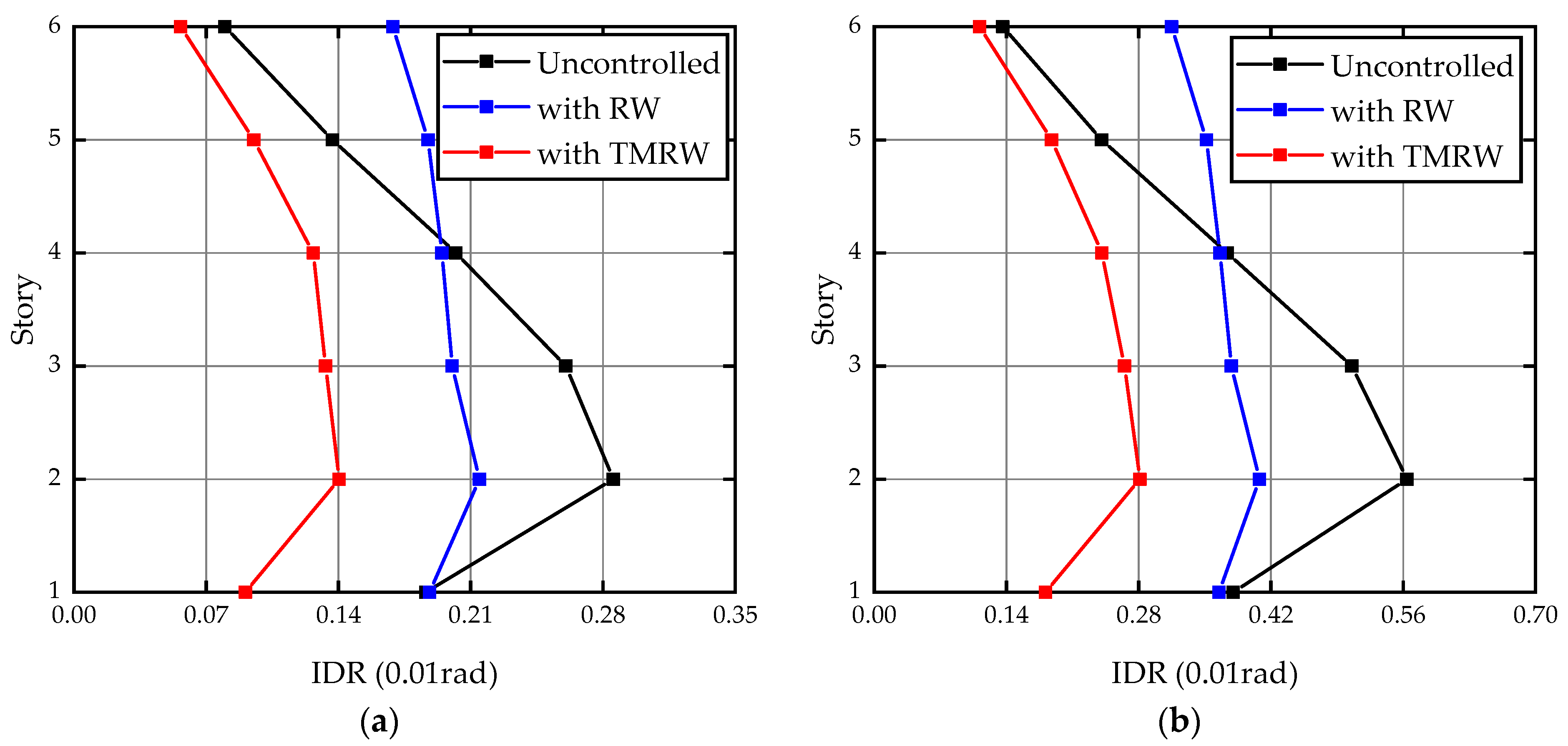
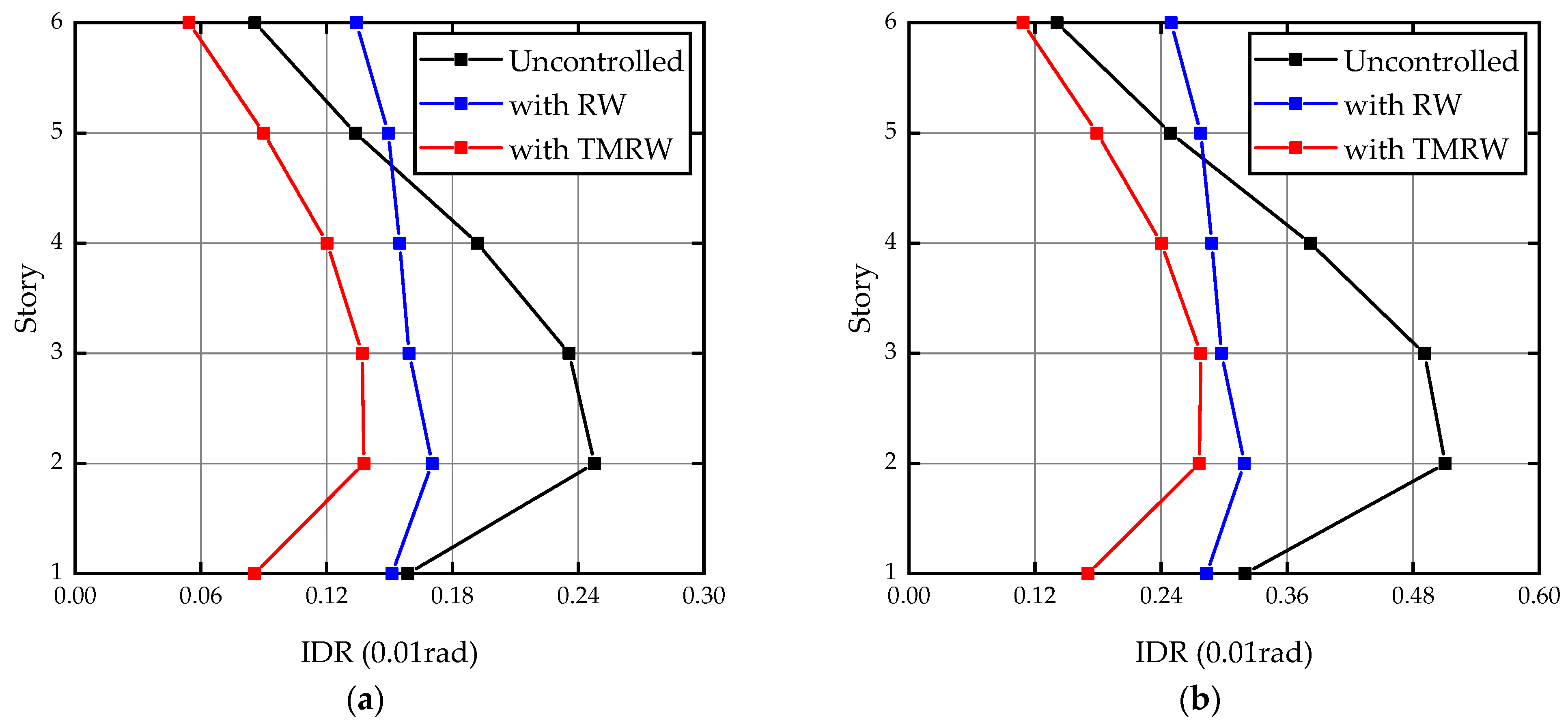
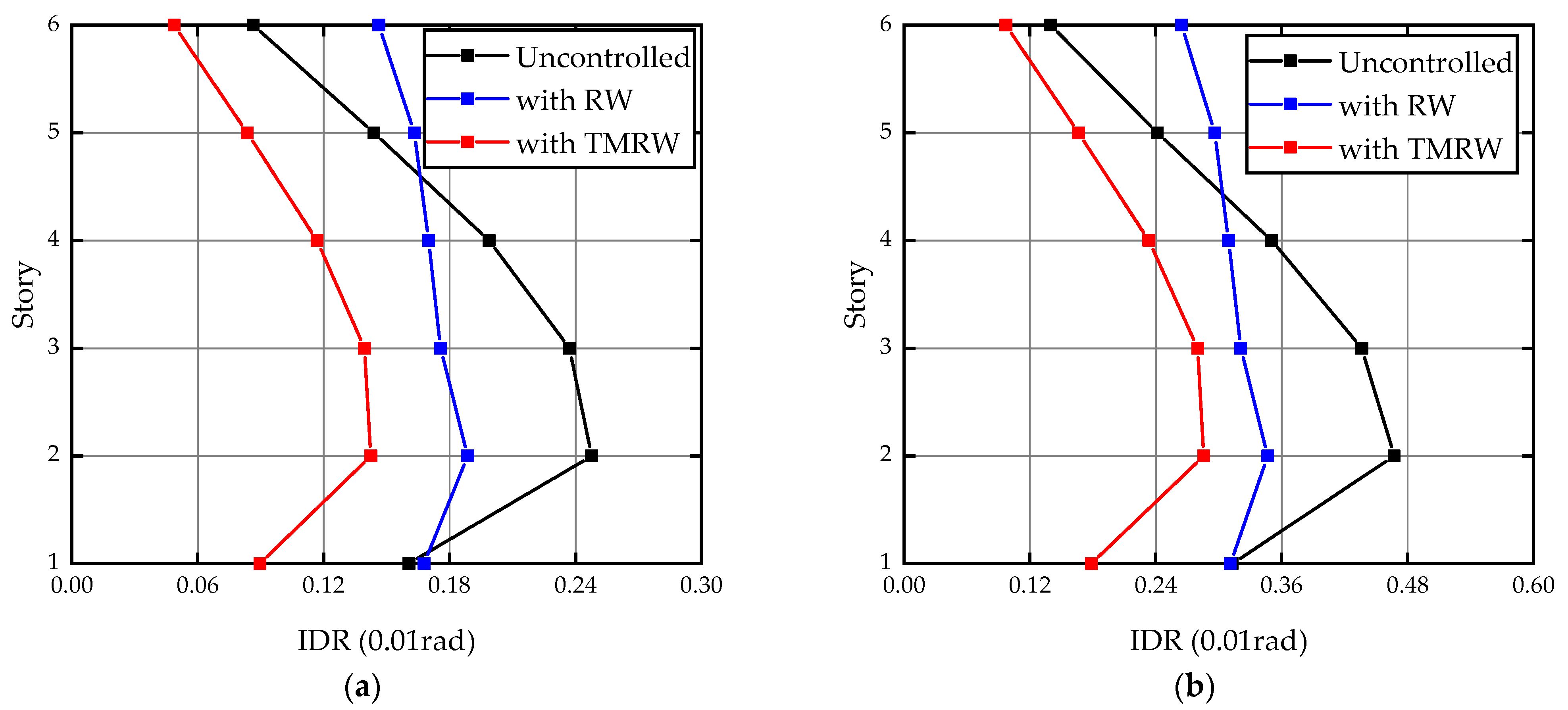
  • TMRW can improve the uneven interstory drift ratio of the frame structure, but its deformation coordination ability is lower than that of traditional RW. Under earthquake excitation, a frame structure equipped with a TMRW can effectively reduce both the displacement response of the weak layer and the acceleration response of the top floor. The control effectiveness of the peak and the RMS displacement are 51.1% and 57.3%, respectively; the peak and the RMS acceleration are reduced by 21.6% and 33.8%, respectively;
  • When subjected to Taft earthquake, the RW designed by using the traditional TMD parameter optimization formulas exhibited poor seismic behavior compared with TMRW. The weaker performance may be attributed to the detuning of TMRW parameters.
  • In the proposed TMRW system, the mass ratio and the connecting stiffness are two key parameters that influence the control performance. Furthermore, since a larger mass ratio leads to higher costs when implementing the system, it is necessary to further study the energy dissipation capacity of the TMRW under different mass ratios, especially with lower mass ratios. Additionally, the control performance of TMRW and the failure modes under mass earthquake excitation should also be examined in structures with different height-width ratios.

Author Contributions

Conceptualization, methodology, validation, investigation, A.W. and W.L.; software, A.W.; formal analysis, A.W.; resources, A.W., W.L. and S.C.; data curation, A.W.; writing—original draft preparation, A.W.; writing—review and editing, S.C. and A.Q.; visualization, W.L., S.C. and A.Q.; supervision, A.Q. All authors have read and agreed to the published version of the manuscript.

Funding

This research was funded by the National Natural Science Foundation of China, grant number 51678158, 51578159, and 51878181 and the National Natural Science Foundation of Fujian Province, China (No. 2018J01773), the Science and Technology Major Project of the Science and Technology Department of Fujian Province (2019HZ07011).

Institutional Review Board Statement

Not applicable.

Informed Consent Statement

Not applicable.

Data Availability Statement

The data presented in this study are available on request from the corresponding author.

Conflicts of Interest

The authors declare no conflict of interest.

References

  1. Cao, H.; Pan, P.; Ye, L.; Qu, Z.; Liu, M. Seismic Performance Analysis of RC Frame Rocking-wall Structure System. J. Archit. Civ. Eng. 2011, 28, 64–69. (In Chinese) [Google Scholar]
  2. Shehu, R.; Angjeliu, G.; Bilgin, H. A Simple Approach for the Design of Ductile Earthquake-Resisting Frame Structures Counting for P-Delta Effect. Buildings 2019, 9, 216. [Google Scholar] [CrossRef] [Green Version]
  3. Qu, Z.; Akira, W.; Ye, L. Seismic retrofit of frame structures using rocking wall system. J. Build. Struct 2011, 32, 11–19. (In Chinese) [Google Scholar]
  4. Ajrab, J.J.; Pekcan, G.; Mander, J.B. Rocking wall-frame structures with supplemental tendon systems. J. Struct. Eng. 2004, 130, 895–903. [Google Scholar] [CrossRef]
  5. Qu, Z.; Ye, L. Seismic damage mechanism control of rocking wall-frame system. Earthq. Eng. Eng. Vib. 2011, 31, 40–50. (In Chinese) [Google Scholar]
  6. Guo, T.; Chen, C.; Xu, W.; Sanchez, F. A frequency response analysis approach for quantitative assessment of actuator tracking for real-time hybrid simulation. Smart Mater. Struct. 2014, 23, 045042. [Google Scholar] [CrossRef]
  7. Makris, N.; Aghagholizadeh, M. The dynamics of an elastic structure coupled with a rocking wall. Earthq. Eng. Struct. Dyn. 2017, 46, 945–962. [Google Scholar] [CrossRef]
  8. Qu, Z. Study on Seismic Damage Mechanism Control and Design of Rocking Wall-Frame Structures. Doctor Thesis, Tsinghua University, Beijing, China, 2010. (In Chinese). [Google Scholar]
  9. Qu, Z.; Wada, A.; Motoyui, S.; Sakata, H.; Kishiki, S. Pin-supported walls for enhancing the seismic performance of building structures. Earthq. Eng. Struct. Dyn. 2012, 41, 2075–2091. [Google Scholar] [CrossRef]
  10. Feng, Y.; Wu, J.; Meng, S.; Wang, Q.; Fu, K. Aseismic performance analysis of rocking wall frame structures with buckling-restrained braces in base. Vib. Shock 2016, 35, 35–40. (In Chinese) [Google Scholar]
  11. Chen, X.; Takeuchi, T.; Matsui, R. Simplified design procedure for controlled spine frames with energy-dissipating members. J. Constr. Steel Res. 2017, 135, 242–252. [Google Scholar] [CrossRef]
  12. Takeuchi, T.; Chen, X.; Matsui, R. Seismic performance of controlled spine frames with energy-dissipating members. J. Constr. Steel Res. 2015, 114, 51–65. [Google Scholar] [CrossRef] [Green Version]
  13. Zhang, W.; Li, G. Seismic fragility study on rocking wall-frame system with dampers. Eearthq. Eng. Eng. Vibrat. 2020, 40, 71–80. (In Chinese) [Google Scholar]
  14. Collini, L.; Garziera, R.; Riabova, K.; Munitsyna, M.; Tasora, A. Oscillations control of rocking-block-type buildings by the Addition of a tuned pendulum. Shock Vib. 2016, 2016, 8570538. [Google Scholar] [CrossRef] [Green Version]
  15. Di Egidio, A.; Pagliaro, S.; Fabrizio, C.; de Leo, A.M. Seismic performance of frame structures coupled with an external rocking wall. Eng. Struct. 2020, 224, 111207. [Google Scholar] [CrossRef]
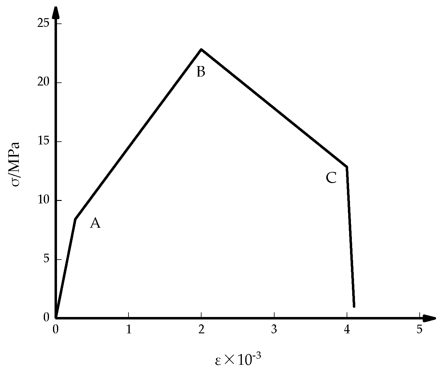
  16. Pian, C.; Liu, Z.; Tao, Y.; Lu, G. Revised plasticity damaged constitutive model of reinforced concrete equivalent material and its application in seismic analysis. Build. Struct. 2015, 45, 19–24. (In Chinese) [Google Scholar]
  17. Rana, R.; Soong, T.T. Parametric study and simplified design of tuned mass dampers. Eng. Struct. 1998, 20, 193–204. [Google Scholar] [CrossRef]
Figure 1. Schematic model of TMD.
Buildings 11 00293 g001
Figure 2. Schematic model of TMRW: (a) TMRW-1 model; (b) TMRW-2 model; (c) TMRW-3 model.
Buildings 11 00293 g002
Figure 3. Dynamic amplification for f = 1 , μ = 1 / 4 .
Buildings 11 00293 g003
Figure 4. Comparison of TMRW-1 and TMRW-2 controlled dynamic amplification.
Buildings 11 00293 g004
Figure 5. Comparison of displacement responses with and without TMRW.
Buildings 11 00293 g005
Figure 6. Plane finite element model.
Buildings 11 00293 g006
Figure 7. Constitutive model of the frame column.
Buildings 11 00293 g007
Figure 8. Acceleration response spectra of earthquake waves and the natural frequencies of structural modes.
Buildings 11 00293 g008
Figure 9. Comparison of the IDRs under El Centro earthquake excitation: (a) 0.1 g case; (b) 0.2 g case.
Buildings 11 00293 g009
Figure 10. Comparison of the IDRs under Taft earthquake excitation: (a) 0.1 g case; (b) 0.2 g case.
Buildings 11 00293 g010
Figure 11. Comparison of the IDRs under Wenchuan earthquake excitation: (a) 0.1 g case; (b) 0.2 g case.
Buildings 11 00293 g011
Figure 12. Comparison of the displacement responses (the second floor): (a) El Centro earthquake excitation (0.1 g); (b) El Centro earthquake excitation (0.2 g); (c) Taft earthquake excitation (0.1 g); (d) Taft earthquake excitation (0.2 g); (e) Wenchuan earthquake excitation (0.1 g); (f) Wenchuan earthquake excitation (0.2 g).
Buildings 11 00293 g012aBuildings 11 00293 g012b
Figure 13. Comparison of the acceleration responses (the top floor): (a) El Centro earthquake excitation (0.1 g); (b) El Centro earthquake excitation (0.2 g); (c) Taft earthquake excitation (0.1 g); (d) Taft earthquake excitation (0.2 g); (e) Wenchuan earthquake excitation (0.1 g); (f) Wenchuan earthquake excitation (0.2 g).
Buildings 11 00293 g013
Figure 14. Comparison of the IDRs under Taft earthquake excitation: (a) 0.1 g case; (b) 0.2 g case.
Buildings 11 00293 g014
Table 1. Control effectiveness of the displacement responses (the second floor).
ExcitationValueDisplacement (mm) η
UncontrolledTMRW
El Centro (0.1 g)Peak15.2757.48051.0%
RMS3.3311.51254.6%
El Centro (0.2 g)Peak30.60114.97151.1%
RMS6.0223.01350.0%
Taft (0.1 g)Peak13.1507.21445.1%
RMS3.3041.41257.3%
Taft (0.2 g)Peak26.84014.43046.2%
RMS6.2392.83954.5%
Wenchuan (0.1 g)Peak13.2127.49843.2%
RMS3.6311.77551.1%
Wenchuan (0.2 g)Peak25.28515.00640.7%
RMS6.9893.54549.3%
Table 2. Control effectiveness of the acceleration responses (the top floor).
ExcitationValueAcceleration (m/s2) η
UncontrolledTMRW
El Centro (0.1 g)Peak3.122.9973.9%
RMS0.5830.38633.8%
El Centro (0.2 g)Peak5.9275.939−0.2%
RMS1.0550.76927.1%
Taft (0.1 g)Peak2.7072.12221.6%
RMS0.6020.42529.4%
Taft (0.2 g)Peak4.8154.22912.2%
RMS1.1280.85024.6%
Wenchuan (0.1 g)Peak2.8272.30718.4%
RMS0.7160.50329.7%
Wenchuan (0.2 g)Peak5.6244.61517.9%
RMS1.3741.00626.8%
Table 3. Comparison of control effectiveness under Taft earthquake excitation.
Excitation ResponsesDisplacement (mm) η Acceleration (m/s2) η
TMDTMRWTMDTMRWTMDTMRWTMDTMRW
0.1 gPeak8.9547.21431.91%45.1%2.3932.12211.6%21.6%
RMS1.8951.41242.65%57.3%0.4320.42528.2%29.4%
0.2 gPeak17.67914.43034.13%46.2%4.4584.2297.4%12.2%
RMS3.7812.83939.4%54.5%0.8550.85024.2%24.6%
Publisher’s Note: MDPI stays neutral with regard to jurisdictional claims in published maps and institutional affiliations.

