Article

Experimental Investigation of ECC Jackets for Repair of Pre-Damaged R.C. Members under Monotonic Loading

by
Anthos I. Ioannou
1,*,
Stavroula J. Pantazopoulou
2,
Michael F. Petrou
1 and
Dimos C. Charmpis
1
1
Department of Civil and Environmental Engineering, University of Cyprus, 75 Kallipoleos Str., P.O. Box 20537, 1678 Nicosia, Cyprus
2
Department of Civil Engineering, York University, Bergeron 335C, 11 Arboretum Drive, Toronto, ON M3J 1P3, Canada
*
Author to whom correspondence should be addressed.
Buildings 2021, 11(5), 180; https://doi.org/10.3390/buildings11050180
Submission received: 22 March 2021 / Revised: 17 April 2021 / Accepted: 19 April 2021 / Published: 24 April 2021

Abstract

:
With the advent of strain-hardening cementitious composites (SHCC), an opportunity for alternative jacketing solutions is presented, where the internal confinement exerted by the fibers in the material may effectively encase the structural component, thereby enhancing the strength and deformation capacity in the critical regions. This concept is explored in the present paper through testing of four pre-damaged prismatic flexural reinforced concrete members with various reinforcing deficiencies. Thin SHCC jackets constituted of a fiber-reinforced Engineered Cementitious Composite (ECC) are used to replace the damaged cover without any additional confining reinforcement. An advantage of cover replacement is that strengthening is achieved without altering the dimensions of the members. The experimental results documented the SHCC jackets’ effectiveness as a rehabilitation strategy, enhancing both the strength and ductility of the retrofitted elements and mitigating the deficiency in transverse reinforcement detailing. The strength recovery showed that the cover-thin SHCC jacket sufficed to enhance flexural and shear resistance through confinement and mobilization of stress transfer at the interface with the encased core.

1. Introduction

Several retrofitting methods have been developed for the repair and strengthening of deficient structural elements, a prominent concept being the various forms of jacketing. Such include concrete and steel jacketing [1,2,3,4,5], fiber-reinforced polymer (FRP), SRP and SRG jacketing, either fully wrapped around rectangular section (for strengthening of plastic hinge regions) or in U-shaped layers (for shear strength enhancement) [6,7,8,9,10]. A disadvantage of concrete jackets is the need to provide a layer of external reinforcement in order to mitigate the lack of stirrups, which leads to a minimum jacket thickness in the range of 70 to 100 mm; the increased thickness in some situations is considered a disadvantage, as it interferes with the architectural function of the retrofitted member, while the jacketing scheme takes on the role of a global intervention [11], since it affects significantly the stiffness of the member. Thin jackets (SRP and SRG) are an effective method to reduce the geometric alteration of the member; their strength is controlled by the anchorage of the metallic wires and the adhesion of the grout layer on the substrate [6,7,8,9,10]. FRP jackets represent a well-documented, effective, and quick solution to recover or enhance deformation capacity, mitigating brittle failures without altering the member stiffness; a disadvantage is the cost, the susceptibility to fire, and the decreasing efficiency as more and more FRP layers are added to the jacket. Steel jackets are a very robust option, their only disadvantage being that they are rather expensive and difficult to apply, and for this reason, this solution is only used in high importance structures, such as critical highway bridge piers.
This paper explores the use of Strain-Hardening Cementitious Composites (SHCC) for replacement of concrete cover as a means of retrofitting damaged reinforced concrete structural members. Cover replacement means that the external dimensions of the retrofitted member remain unaltered; the fiber-reinforced cover sustains its tensile strength up to very large levels of tensile deformation, which, in the role of an encasing jacket of the existing member, functions as a confinement mechanism (see Figure 1).
The higher the tensile strength and the strain hardening properties of the SHCC material, the greater the intensity of the effected jacket confinement. Depending on the type of fiber, a high tensile deformation capacity, durability, and reinforcement protection may be achieved; the method of application is simple and can provide an alternative solution for use in the repair and strengthening of reinforced concrete members either as web concrete replacement or as concrete jacket in the areas of plastic hinges of columns [12].
In the present research, an Engineered Cementitious Composite (ECC) reinforced with 12 mm long, 0.039 mm diameter PVA fibers was used to retrofit the cover of four beam–column elements with different types of substandard reinforcement details, which had been previously damaged through the application of monotonically increasing lateral displacement to failure. This material has a very resilient strain-hardening response in direct tension, marked by fine, multiple cracking—therefore, it is an SHCC material. The specimens had been designed using the minimum requirements of EN 1992-1-1, 2004 [13] for lap-splicing of longitudinal reinforcement and for transverse steel reinforcement detailing. Transverse reinforcement comprised smooth bars to simulate old type (pre-1980s) detailing practices. The SHCC material used for cover replacement had already been investigated in Cyprus [14] with demonstrated advantages in terms of ductility and tensile strength. Through testing of the retrofitted components, it was found that the cover replacement is a very effective means of strengthening, enabling a significant increase of deformation capacity and recovery of resistance.
The objective of the present work is to investigate a new form of jacketing of reinforced concrete members with inadequate transverse reinforcement details, where the cover is replaced with a tension-hardening cementitious composite with significant tensile strain resilience after cracking. The contribution of the new cover material to the shear strength and confinement of existing, damaged reinforced concrete columns through concrete cover replacement is investigated through testing. In the following sections, the experimental program, the material laws, the primary loading results, and the application of the retrofit are described in detail, including reference to the observed failure modes, and specimens’ section analysis, as well as the overall performance and efficacy of the retrofitting methodology.

2. Experimental Program

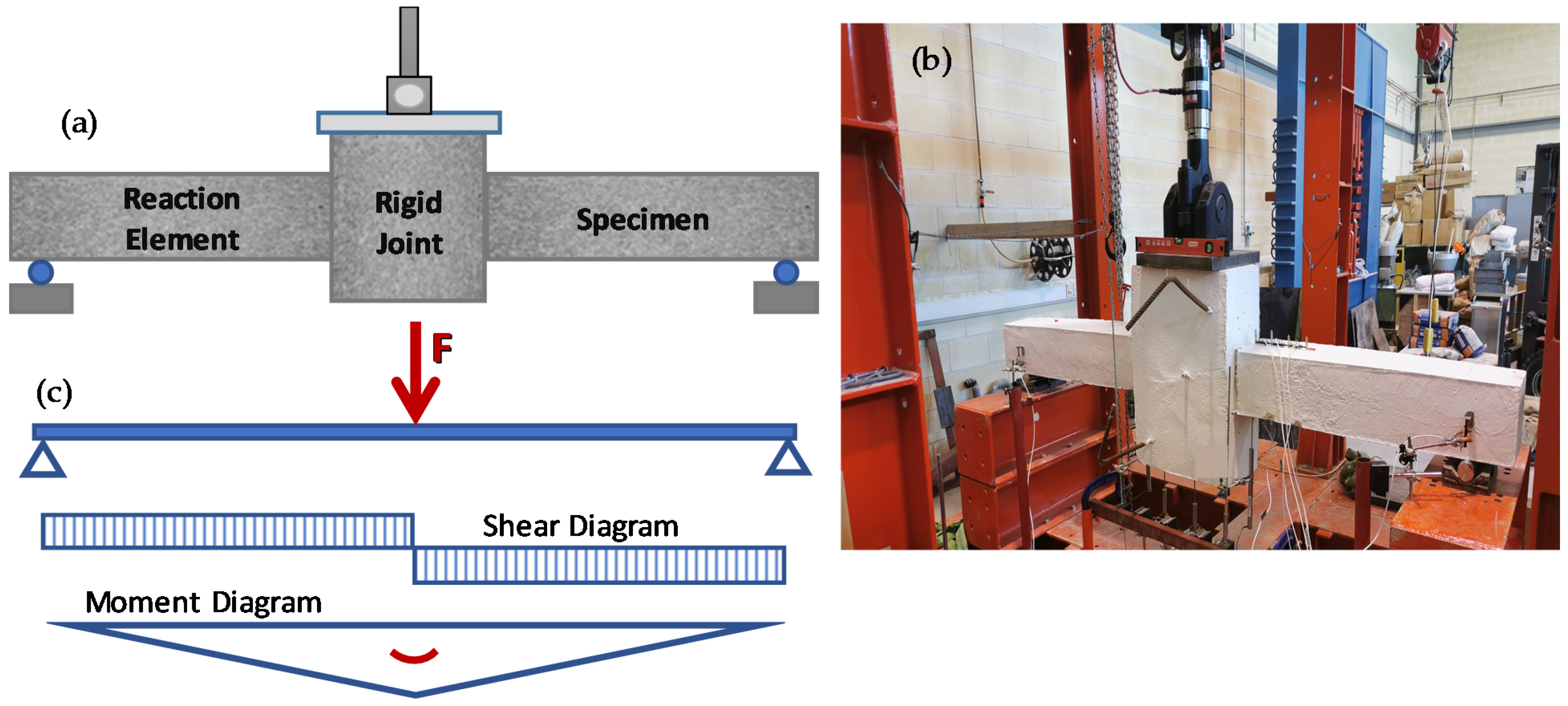
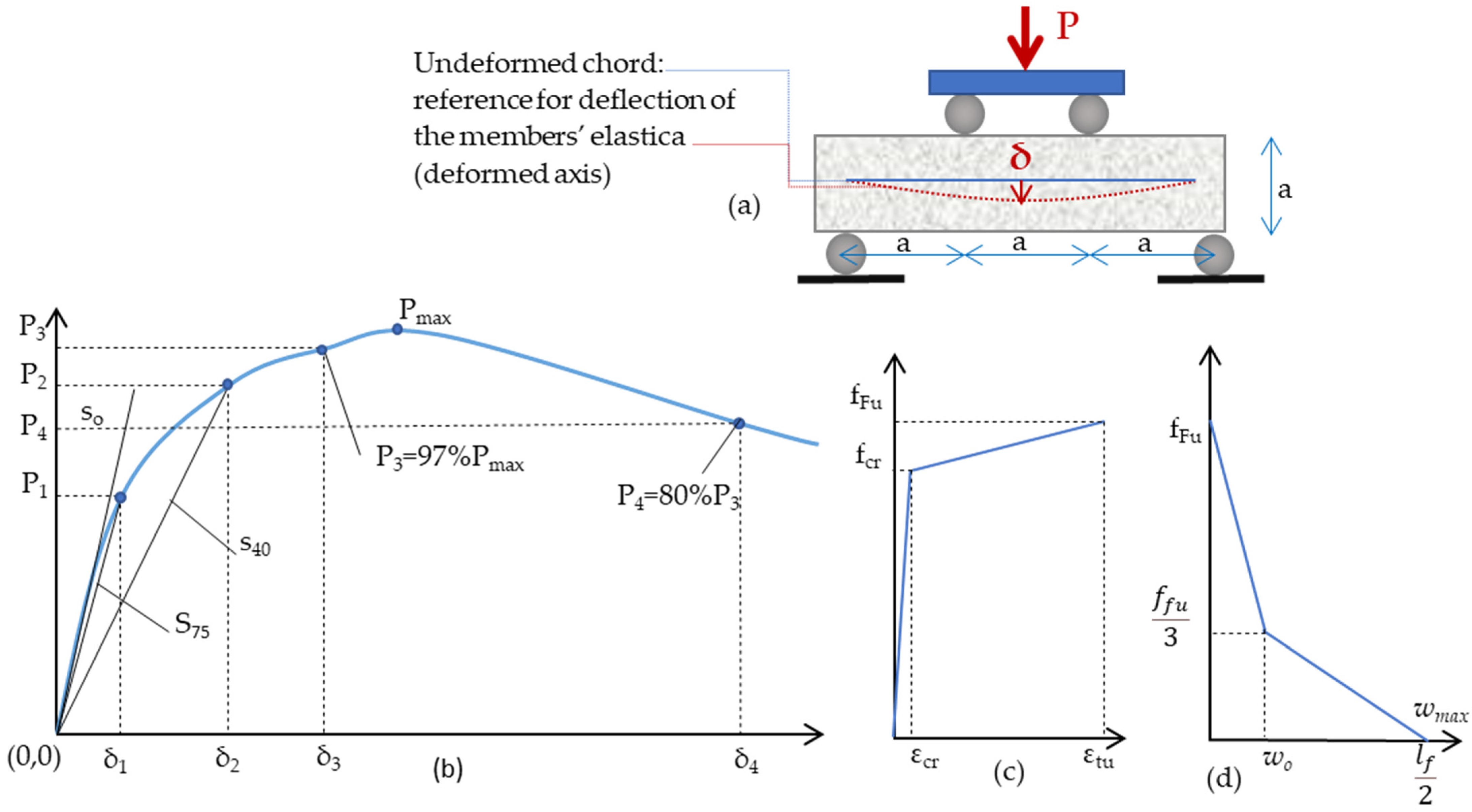
2.1. Experimental Setup

To evaluate the effectiveness of cover replacement with SHCC, four pre-damaged structural components were tested under monotonically increasing lateral displacement. The objective of the tests was to determine whether the thin cover layers comprising strain hardening fiber-reinforced cementitious (FRC) material may effectively provide the benefits of a jacket in confining the structural member, particularly in recovering part of the deformation capacity in the critical regions of the components tested and to quantify the FRC cover contribution to the shear strength of the repaired components. To this end, four specimens of beam/column type were constructed and subjected to monotonic lateral displacement using the setup illustrated in Figure 2a. The experimental testing in the reaction frame using a servo-hydraulic piston, depicted in Figure 2b, was adopted from an older investigation for specimens of similar geometry [15].
Overall, the test setup resembles a simply supported system of a beam–column subassembly loaded at midspan with a point load, which generates the moment and shear diagrams shown in Figure 2c.
Two equal length beam-columns were connected back-to-back in the central stub, which served as the midspan support of the piston. Roller supports were provided at the ends of the subassembly. The load was applied monotonically under displacement control. The central stub modeled the foundation part of a half column subjected to constant shear. The two sides of the subassembly adjacent to the stub represent two half beam-columns; of those, the one shown on the right-hand side is the test specimen, where specific reinforcing details and retrofit measures are studied. The one on the left hand-side of the central stub is a much stronger element (heavily reinforced), which is designed to serve as the reaction specimen. The longitudinal reinforcement of each prismatic member was anchored in the central stub with 90° hooks; the stub was confined with significant amounts of transverse reinforcement (Figure 3).

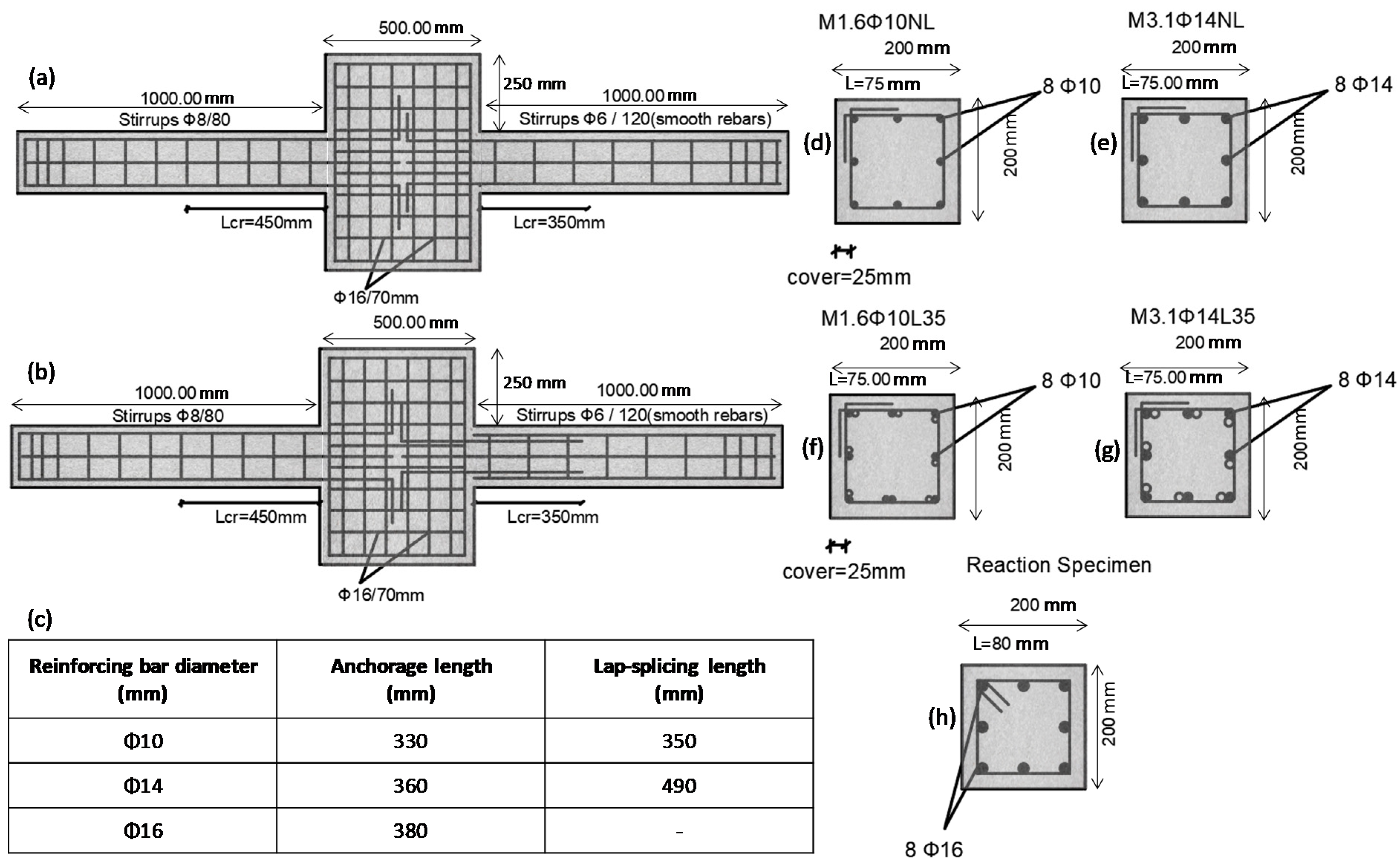
2.2. Parameters of the Test Specimens

Four specimens were constructed, having a 200 mm square cross-section and a length of the test element equal to 1000 mm, whereas the shear span (distance from the face of the stub to the roller support) was Ls = 890 mm. Thus, the moment diagram created resembles the pattern occurring in a structural member that belongs to a lateral load resisting system undergoing lateral sway (i.e., constant shear in the shear span, linearly varying moment from the face of the support to the roller). All test specimens had smooth stirrups comprising 6 mm diameter bars spaced at 120 mm and tied with 90° hooks, as would occur in older construction. Of the four specimens, two had continuous longitudinal reinforcement, whereas the other two had lap spliced longitudinal reinforcement in the critical region extending over a length of 35Φ, where Φ is the longitudinal bar diameter. This was intended to test the influence of an inadequately tied lap-splice on the deformation capacity of the member before and after the retrofit.
Another parameter studied was the magnitude of shear demand in the plastic hinge region, which is affected through adjustment of the longitudinal reinforcement ratio. Thus, by changing the longitudinal bar diameter (Φ, either 10 or 14 mm), the longitudinal reinforcement ratio was altered from 1.6% to 3.1% (note that a Φ10 has a bar area Ab = 78.5 mm2, whereas a Φ14 has Ab = 154 mm2). Following the monotonically increasing displacement of the central stub, all columns developed the expected damage in the critical region. A repairing procedure was applied (ECC jacketing by cover replacement), and the specimens were re-examined under monotonic loading to assess the repair material’s contribution to the lateral load resistance and deformation capacity. Therefore, the results for eight tests are examined in the present study (initial and repaired condition). Specimens are identified by a code name as depicted in Table 1, referring to the layout of reinforcement depicted in Figure 3.

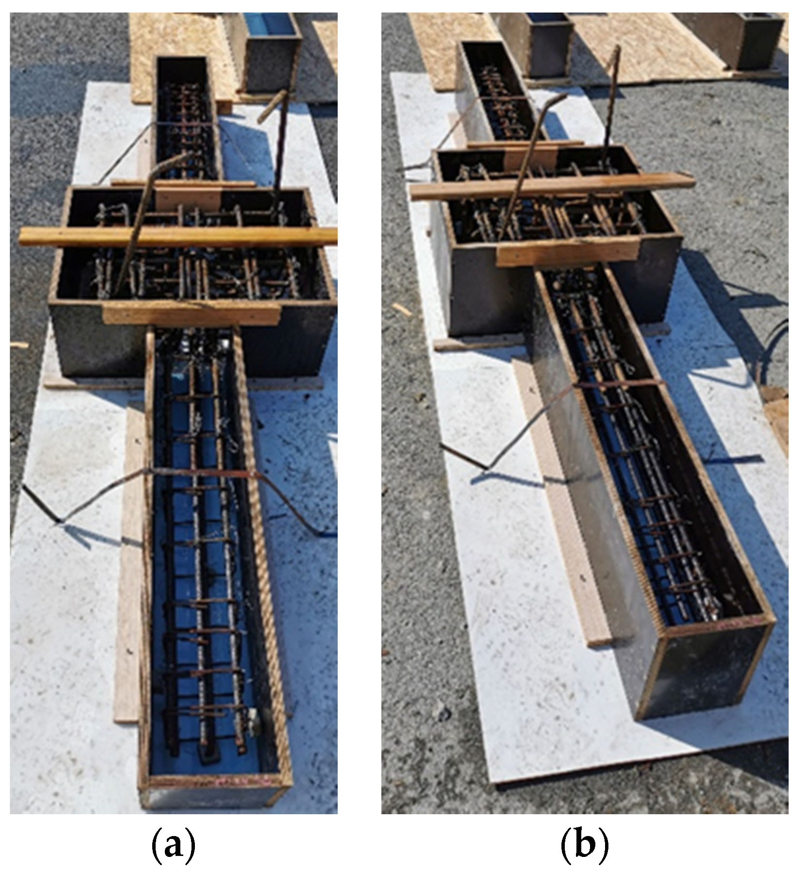
2.3. Specimen Design

Τhe reference specimen that was used as a benchmark for the geometry layout and reinforcement detailing was the ECC specimen tested in [15]. In the reference study, a comparison between two test specimens was made, whereby in one case, the steel reinforcement was configured for Ductility Class M according to EN 1998-1, 2004 [16], whereas in the second case, the minimum transverse reinforcement was provided; however, a fiber-reinforced ECC material was used in the latter case, while the same matrix but without the fibers was used in the former.
Figure 3 and Figure 4 illustrate the geometry of experimental specimens accompanied by the steel reinforcement detailing. The elements’ axial load ratio was ν = 0. All specimens and reaction members have cross-sectional dimensions 200 × 200 mm2, with eight bars symmetrically placed on the cross-section, i.e., three bars per side, as shown in Figure 3. While specimens were reinforced with 10 or 14 mm bars (Table 1), the reaction members were all reinforced with eight, symmetrically placed, 16 mm bars. Clear cover was 25 mm in all cases. During testing, a constant shear force acted in the specimen, equal to ½ of the applied total force at the midspan stub; flexural moment at the critical section was calculated from the product of the shear force times the shear span.
In the present study, emphasis is placed on the development capacity of longitudinal reinforcement over the lap length. Pairs of specimens were designed to have either continuous reinforcement or with lapped bars over a length measured from the face of the central stub, which is equal to 35Φ. The required lap length was calculated as per EN 1992-1-1, 2004 [13], assuming a bond strength fb = 5 MPa, as follows.
The required lap-splice length was obtained from:
l o = a 1 l b , n e t max ( 0.3 a l l b , 15 Φ , 200   mm ) ,
where l b = l b , n e t . In Equation (1), coefficient a 1 is a factor that depends on the geometric conditions of the lap-splice, whereas the required anchorage length is obtained from:
l b , n e t = α · ( Φ 4 · f y d f b d ) l b , m i n .
Here, α = 1 for a straight anchorage and α = 0.7 if (a) hooks are formed and the bars are stressed in tension or if (b) transverse bars have been welded on the anchored bar. Length l b , m i n = max ( 0.3 l b   or   0.6 l b ) for bars in tension or compression, respectively. Upon substitution, it was found that l o = 2 · ( 0.25 · Φ · 500 / 5 ) = 50 Φ (with a 1 = 2). In the present investigation, the estimated required lap-slice lengths for anchorage are shown in the insert table of Figure 3c. Where lap-splicing has been used, a shorter lap than the required value was provided (i.e., 35Φ as compared to 50Φ) to represent older practices of construction. The lapped bar-pairs were placed side by side at the top and bottom sides of the cross-section, as depicted in Figure 3f,g To further emulate old reinforcing practices, stirrups were spaced at distances of 120 mm, i.e., 12Φ and 8.5Φ for the two utilized sizes of longitudinal bars, respectively. Pictures of specimens’ actual steel reinforcement configurations are provided in Figure 4.

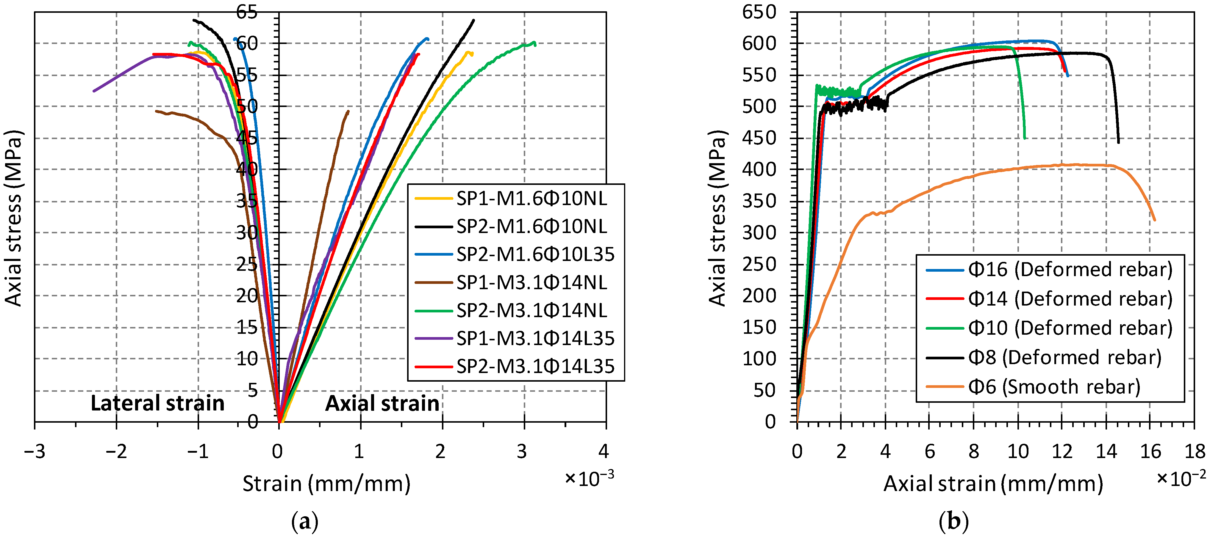
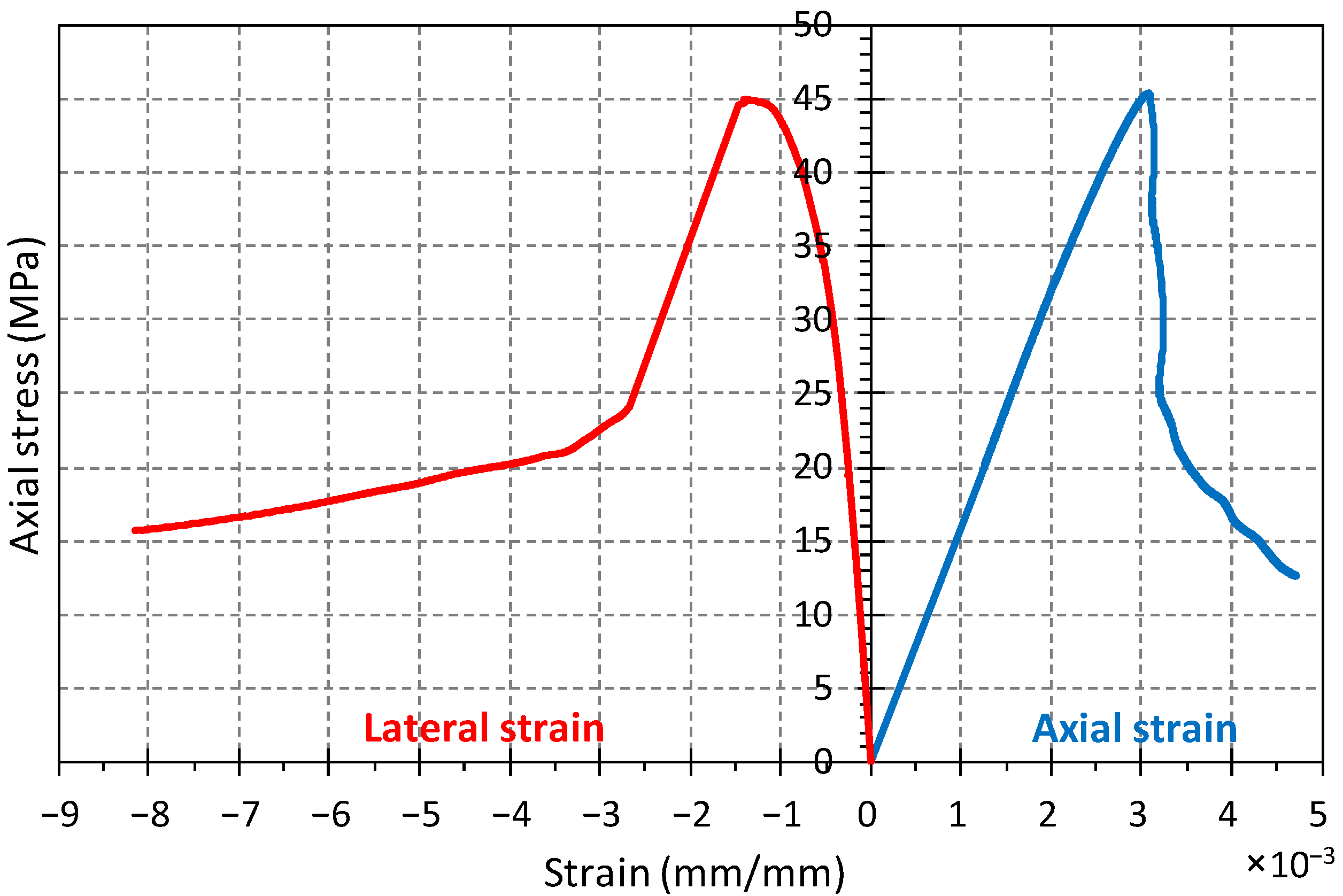
2.4. Material Properties

Table 2 presents the mix design for standard concrete and the resulting average compressive strengths obtained after 28-day testing of 100 mm diameter by 200 mm height cylinders in uniaxial compression. The corresponding axial compressive stress vs. axial and lateral strain diagrams are plotted in Figure 5a. The uniaxial tensile stress-strain diagrams of steel reinforcement (all bar sizes) are plotted in Figure 5b.
Figure 6 illustrates the crack pattern of specimens after monotonic loading up to an advanced level of damage or failure, whichever occurred first. Tests of specimens with continuous reinforcement were terminated at a nominal drift ratio of 5%; specimens with lap-spliced reinforcement failed at a corresponding nominal drift ratio of 3%. As shown in Figure 6a, a through vertical crack developed at the face of the support of specimen M1.6Φ10ΝL, combined with flexure and shear-flexure cracks. Specimen M3.1Φ14ΝL also developed flexure-shear cracking, but eventually tensile reinforcement pullout from the central stub dominated the response, as may be observed from the initiating horizontal crack on the adjacent stub at this point. For both specimens M1.6Φ10L35 and M3.1Φ14L35, where reinforcement was lap-spliced in the critical zone, a brittle shear failure was observed, which was accompanied by shear cracks starting from the overlapping endpoint.
The response curves obtained are presented together with those of the retrofitted counterparts in later sections of this paper. The response was marked by an almost linear ascending branch up to a drift ratio of about 1% for M1.6Φ10NL and M1.6Φ10L35, and up to about 1.5% for specimens M3.1Φ14NL and M3.1Φ14L35; peak strengths were attained roughly at 3% drift ratio for the specimens with continuous reinforcement, but strength degradation started earlier (at about 2.5% drift ratio) for the lap-spliced specimens. The drift level where each specific crack occurred is shown in Figure 6 (numerals on the specimen faces near the cracks represent the drift level at which the crack had propagated up to the point that is adjacent to the numeral). A brittle failure was observed in the lap-spliced specimens, which was marked by dense diagonal cracking, with a clear splitting crack propagating along the lap splice. No reinforcement ruptures were observed; longitudinal reinforcement yielded extensively with yield penetration into the central stub and significant pullout slip at the support, whereas, owing to the poor anchorage of the stirrups, the transverse reinforcement did not reach the yield point.

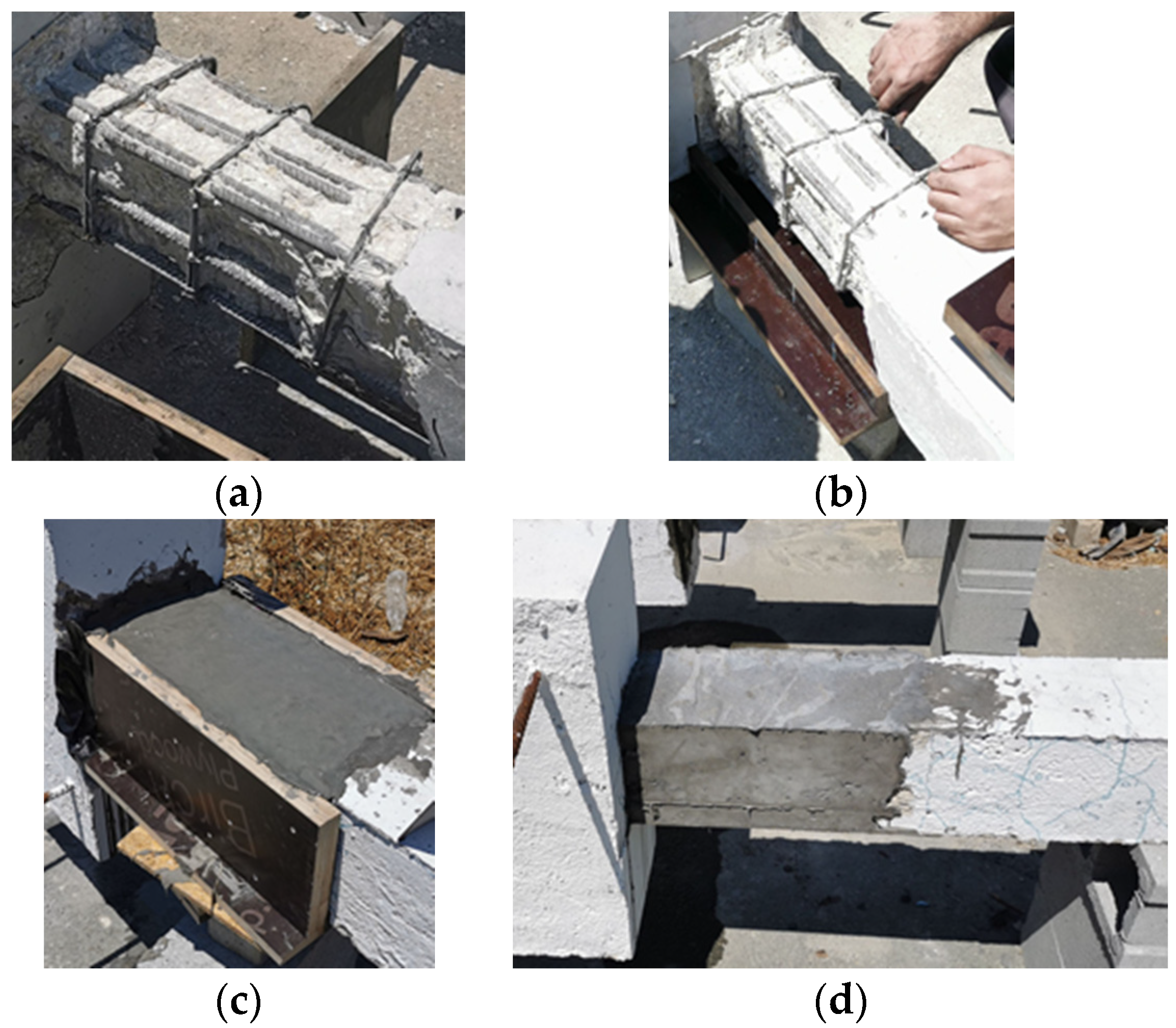
2.5. Retrofitting Procedure

The procedure for repair and strengthening was carried out after completion of the monotonic tests. All tested specimens were retrofitted in the critical region (starting from the face of the support, the repair length was h c r = 2 b w ) after removal of the damaged cover, as depicted in Figure 7a, using a small electric concrete hammer until all the reinforcement was revealed. Where the damaged region extended into the central stub, this was also included in the retrofit. The removed concrete cover was replaced using an inhouse-made ductile, fiber-reinforced cementitious composite (ECC) material, which was placed to also function in the role of a jacket. The mix design of the ECC material is listed in Table 3. The material was workable, self-consolidating with a pot life that extended to about 40 min after mixing.
Figure 7b,c depict the placement of the ECC material in the cover of the specimen, lying in the horizontal direction during repair as during testing. To facilitate placement, an extendable form was used; first, the lower layer (bottom cover) was cast, as shown in Figure 7b, with the sides of the form extending upwards only 40 mm. Then, the extensions to the side forms were placed as shown in Figure 7c, and the side cover was cast, whereas the top cover and finishing of the free surface followed. Where cracking had been detected in the reaction members, they were strengthened with high strength repair mortar and CFRP wraps, in order to enhance their reacting capacity to the repaired study specimens.

2.6. Repair Material

The mix design for the repair ECC material used for cover replacement is listed in Table 3. PVA fibers having a tensile strength of 1600 MPa, a Young’s Modulus of 40 GPa, density of 1300 kg/m3, length of 12 mm, and diameter of 39 μm were added at a volumetric ratio of 1.25%. Then, 75 mm in diameter by 150 mm-high ECC cylinders were tested in compression under displacement control in order to characterize the compressive stress–strain properties of the cementitious repair material. Figure 8 presents the average axial compressive strain vs. axial and circumferential strain of the tested specimens. Flexural prisms having a cross-section of 60 × 100 mm2 and a span of 180 mm were tested under four-point loading (with the applied loads acting at the third points of the span). The objective of these tests was to obtain the tensile stress–strain response of the material through inverse analysis; the detailed description of the procedure used is provided in the following paragraphs and Appendix A.
Yang et al. 2020 [17] used the inverse analysis method to determine the critical points of the tension stress–strain response of the material using the approach adopted by the CSA-S6 Annex 8 (2019) [18], which was originally proposed by Lopez (2017) [19]. The procedure requires the resistance curve from third-point loading as depicted in Figure 9a, where the total applied vertical load is P and the midspan displacement is δ. Note here that the midspan displacement must be measured with reference to the chord of the deformed specimen (i.e., with reference to the chord of the member, which is the line that connects the midpoints of the sections directly above the supports). This is achieved either using a jig mounted on the specimen that supports the linear variable differential transducers (LVDTs), in order for the relative displacement to be obtained directly, or three LVDTs are used, in order to measure both the midspan deflection and the support displacements from a stationary reference, so that the relative displacement δ may be obtained (the latter was used in this study).
The slope of the ascending branch of the curve, so, defines the point ( P ο ,   δ ο ) and the intersection of the straight lines from (0,0) with inclination 75% and 40% of so, which are denoted as s 75 and s 40 , with the envelope curve, determines the points ( P 1 ,   δ 1 ) and ( P 2 ,   δ 2 ) . Additionally, ( P 3 ,   δ 3 ) and ( P 4 ,   δ 4 ) correspond to the 97% of maximum load and 80% of P 3 in the post-peak range, respectively.
Using the coordinates of these points from the resistance curve of the prism specimens, the milestone points of the tensile stress–strain response of the material are obtained, as shown in Figure 9b; note that the obtained tensile behavior comprises a stress–strain part that describes the ascending and strain-hardening part of the response (f-ε), which is followed by a stress-crack opening displacement (f-w), where the maximum crack width, w, is limited by half the length of fiber used, lf (i.e., here wmax = 6 mm).
A summary of the inverse analysis steps and the related mathematical relationships, which are used in conducting the calculations, is provided in Appendix A. Following the application of this procedure, the results obtained for the characteristic tensile stress–strain response of the ECC material are given in Table 4.

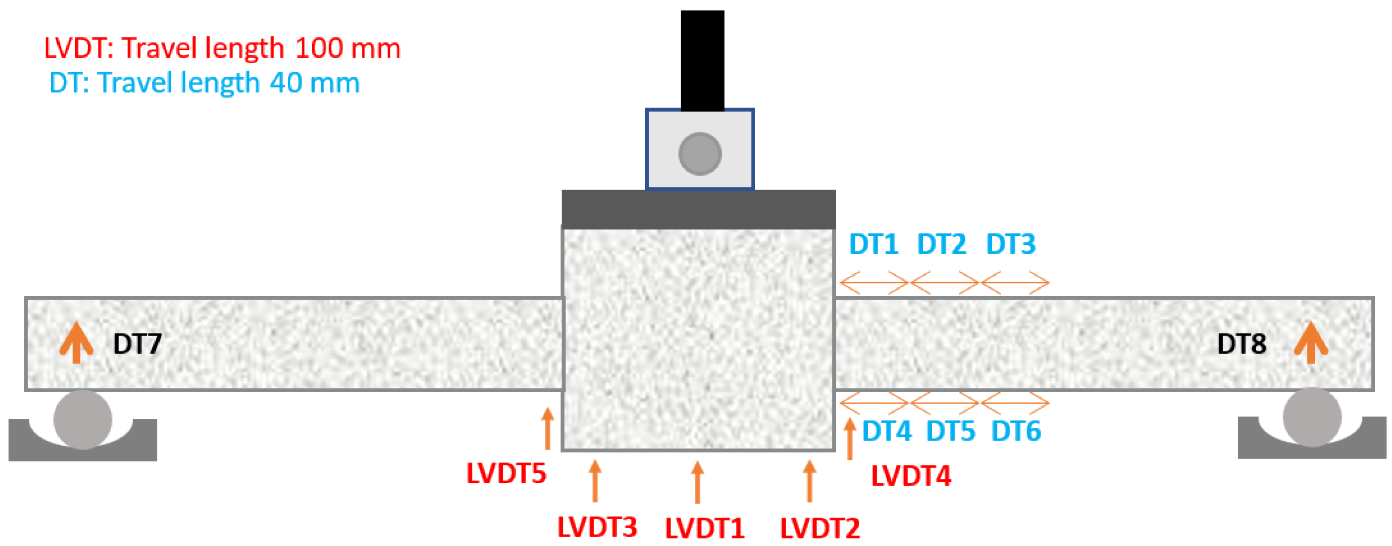
2.7. Instrumentation

The instrumentation layout included five LVDTs (defined earlier) and eight displacement transducers (DTs) of different nominal gauge lengths (see Figure 10) to record the specimens’ deformations and displacements during the experiment. The positioning of the whole instrumentation equipment is depicted in Figure 10. For monitoring of the vertical deflection, five LVDTs were installed at the bottom center point of the element. DTs 7 and 8 were positioned at the ends of shear spans to measure the centroidal axis’s vertical displacement, and DTs 1 to 6 were installed at the top and the bottom sides of experimental specimens at the areas where the development of plastic hinge was expected. All measuring instruments were supported on an independent steel beam without having any contact with the reacting steel frame that supported the hydraulic piston.

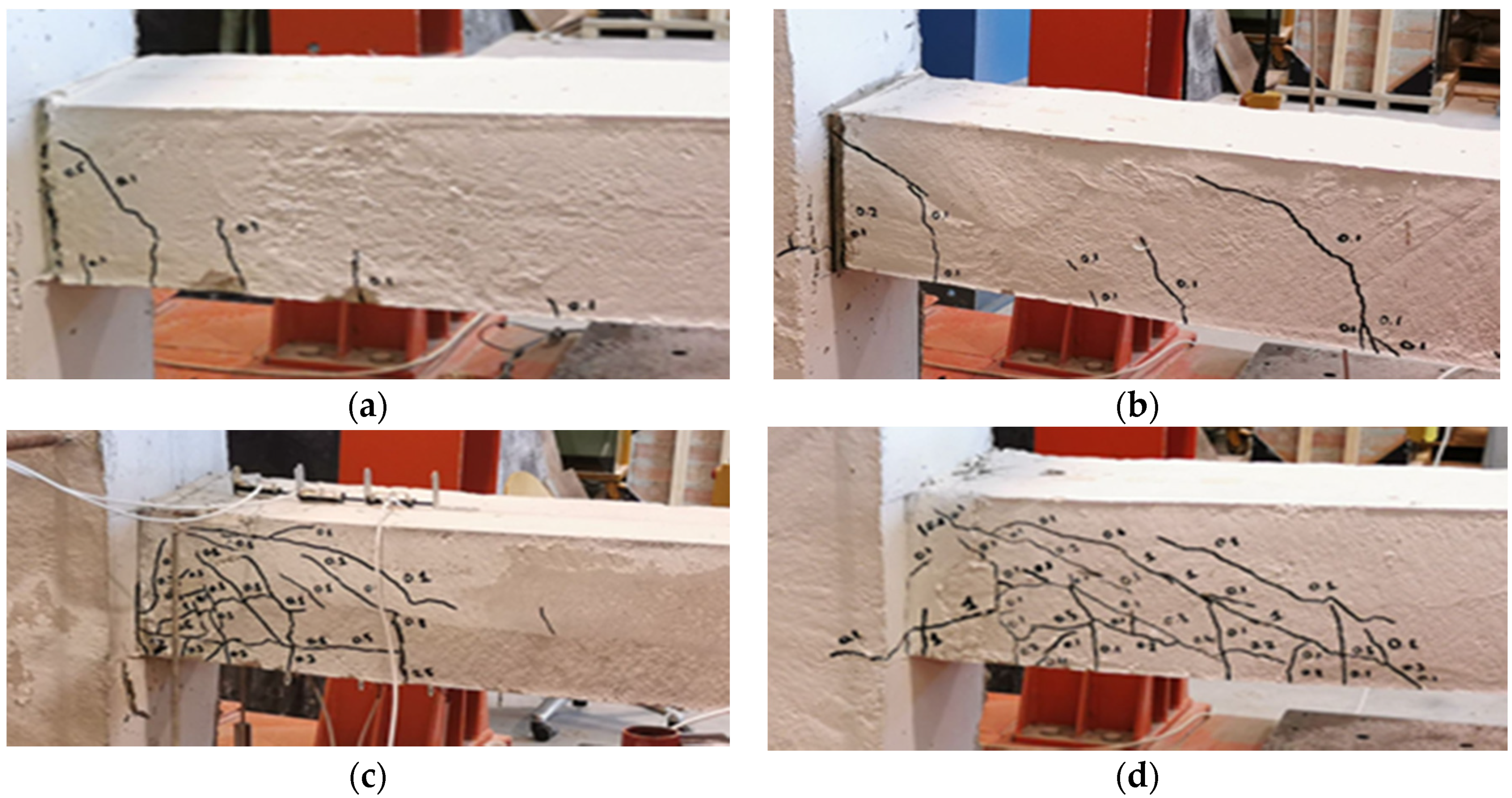
3. Observed Experimental Response

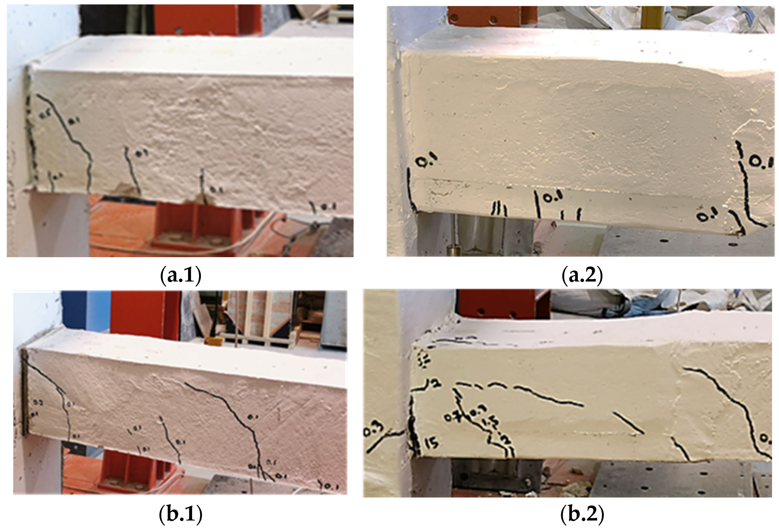
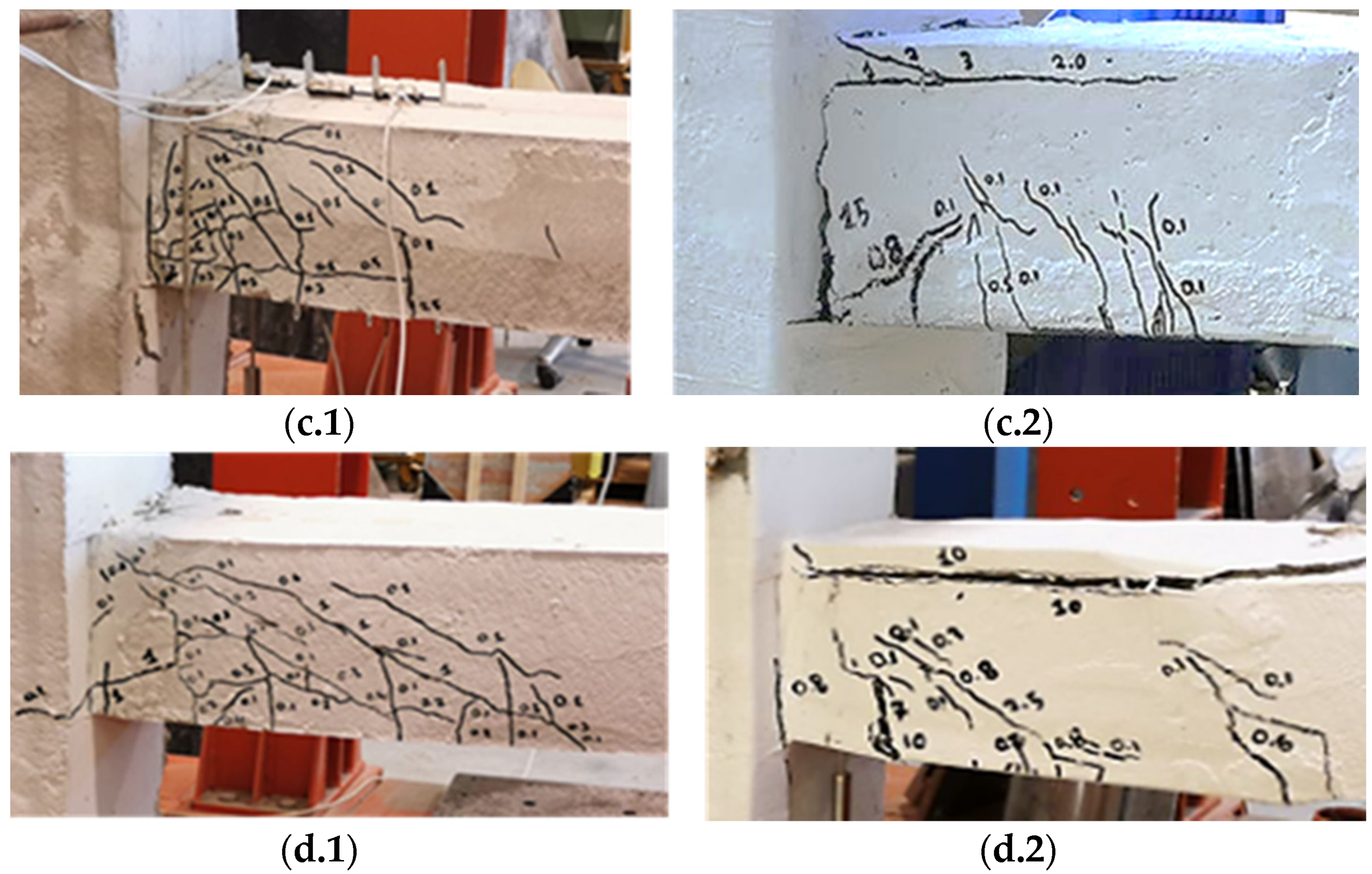
3.1. Damage Profiles and Resistance Curves

The responses of the retrofitted specimens obtained after monotonically increasing midspan load applied under displacement control are compared with the original specimens in Figure 11 and Figure 12. The failure modes are compared for the original and the retrofitted specimens placed side by side in Figure 11. Figure 12 plots the experimentally obtained resistance curves for the original and the retrofitted specimens; the vertical axis plots the shear force developed in the shear span of the specimen (i.e., it is half the total applied load), whereas the drift ratio plotted in the horizontal axis is the nominal chord rotation of the deforming member, which is calculated as the ratio of midspan displacement divided by the deformable length of the member from the face of the support to the end roller.
Note that all specimens in the original condition developed a brittle response after attainment of the peak load. On the contrary, retrofitted specimens with continuous reinforcement attained their peak load at a drift ratio of about 3% and showed spectacular deformation capacity and resilience up to nominal drift levels that exceeded the limit of 5% (see Figure 12). For example, specimen RM1.6Φ10ΝL, containing a low reinforcing ratio and continuous bars extending into the central stub, developed a purely flexural response marked by cracks oriented normal to the neutral axis of the element; the same behavior was observed in the case of specimen RM3.1Φ14ΝL, despite the very high shear demand effected by the larger size of longitudinal bars; however, in this case, diagonal cracking did occur particularly beyond a drift ratio of 1.5%.
During primary loading, specimens with continuous longitudinal reinforcement had developed shear and shear-flexure cracks of maximum length 200 mm and width 0.2–0.3 mm. Lap-splicing specimens had shown densely combined diagonal and horizontal crack patterns of length and width 300 mm and 1–2 mm, respectively. On the other hand, failure modes of retrofitted elements showed a lighter crack profile, with cracks extending to shorter lengths and with smaller crack width openings in the critical region. A wide vertical crack that pre-existed from the first phase of loading at the face of the support, owing to the anchorage slip from the footing, which occurred in the primary loading phase, persisted in the post-repair phase.
It is noted that the contribution of the ECC cover in both cases is significant, despite the fact that the average compressive strength of the ECC material was inferior to that of the original specimens; the improved behavior is evidently owing to the confining contribution of the jacket material in the compression zone, but also it is due to the contribution of the tensile strength of the material beyond cracking in the section equilibrium (a resultant tensile force develops in the concrete tension zone).
The specimens containing lap splices showed inferior performance to those with continuous reinforcement when tested in the original condition (see Figure 11c.1,d.1, and the green lines in the resistance envelopes of Figure 12c,d). Although the replacement of the cover could not fully recover the original strength of the specimens due to permanent damage in the joint region (anchorage), a much more resilient response was obtained after retrofit; the extent of cracking was also less after retrofit, underscoring the strain hardening response of the cover material in tension.
The compressive layer of the replaced cover spalled off in the cases of RM1.6Φ10L35 and RM3.1Φ14L35 at relatively large levels of drift, which was dominated by reinforcement pullout from the anchorage (a damage caused in the first phase of loading, which could not be repaired without invasive operation in the rigid side of the stub; this was not done because it was deemed to be beyond the scope of the study, which focused on cover replacement only).
To illustrate the strength recovery that was effected by the retrofit procedure, sec-tional analysis of the specimen cross-sections shown in Figure 1, considering the original condition of the cover, as well as its replaced condition as per Figure 1c, is pursued in the following section.

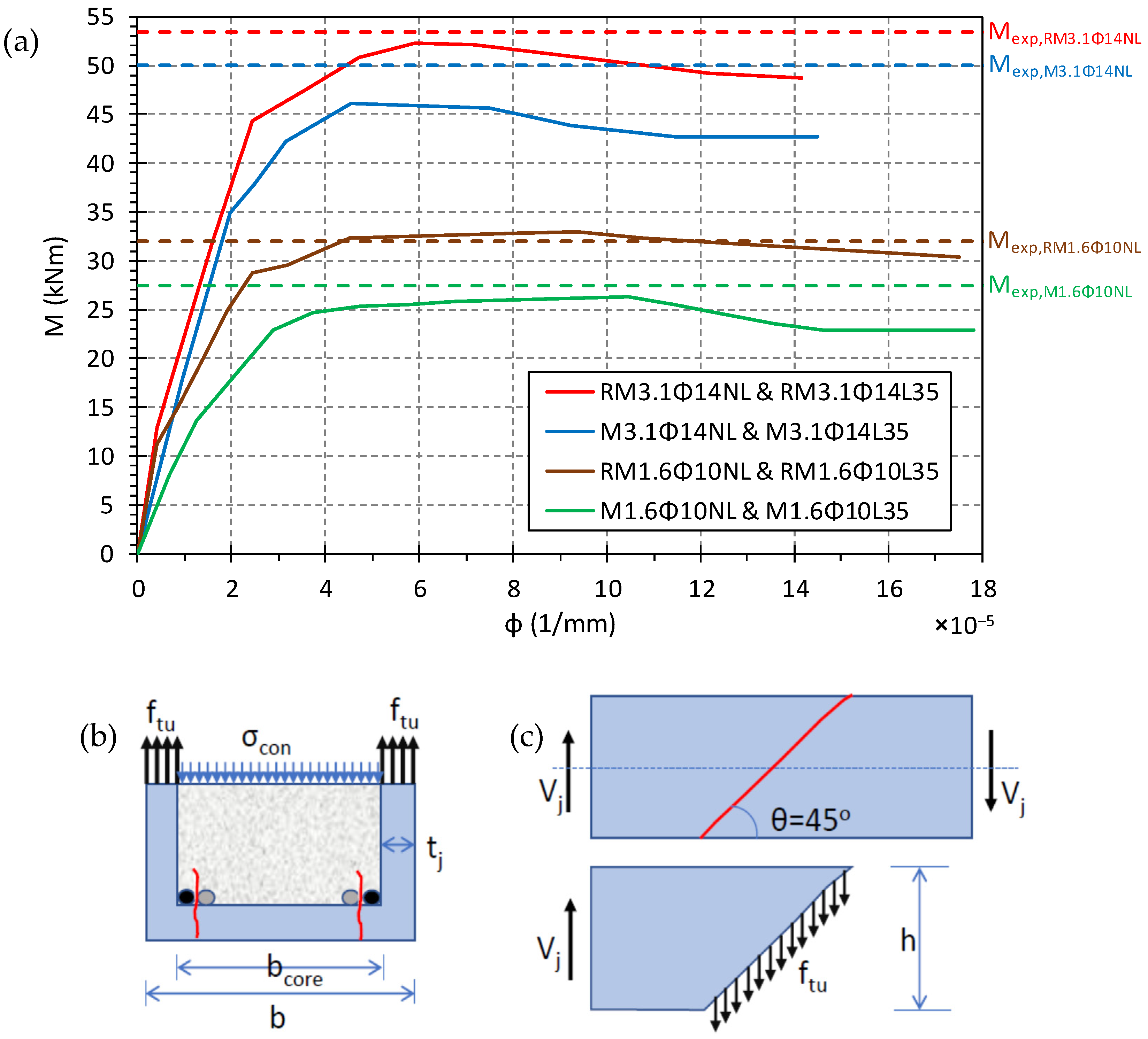
3.2. Evaluation of the Flexural Strength of the Specimens

Calculation of the flexural moment vs. curvature of the cross-sections of the specimens with continuous reinforcement was conducted using the basic concepts of the theory of flexure (plane sections remaining plane, discretization of the cross-section in layers and numerical integration). Material stress-strain laws were as follows: (a) for concrete and ECC concrete in compression, a basic Hognestad-type parabola (1951) [20] was used to describe the ascending branch, each material attaining its respective peak compressive strengths (as per Table 2 and Table 4) at a compressive strain of 0.002 and 0.0027 for plain and ECC concretes, respectively; the Kent and Park (1982) [21] model was used for the post-peak descending branch, using strain values of ε c , 50 = 0.003 and 0.004, respectively (this is the strain in the post-peak range where compressive strength has been degraded to 50% of peak). The tensile strength of plain cover was neglected in the analysis of the original sections. However, the tensile strength of the ECC cover was accounted for in calculating the forces developed in the sectional layers that fell within the tension zone of the repaired sections using a bilinear, elastic–perfectly plastic stress–strain diagram for the tensile response prior to crack localization (at ε t u = 0.0092, see Figure 9c and Table 4). The slope of the ascending branch was set equal to the elastic modulus of the ECC (=18300 MPa). A bilinear elastic–perfectly plastic diagram of stress and strain curve for steel reinforcement was considered, the yield point being defined as per Figure 5b.
The calculated moment–curvature diagrams are plotted in Figure 13 for the typical cross-sections of specimens M1.6Φ10ΝL, RM1.6Φ10ΝL, M3.1Φ14ΝL, and RM3.1Φ14ΝL. The strength obtained in the respective test is plotted as well. It is noted that strength values are approximated closely by the flexural theory. Evidently, the actual influence of the ECC cover replacement is remarkable, underscoring the confining effectiveness of the jacket as well as its sustained tensile resilience to large strain levels, which was also sufficient to compensate for the initial stiffness loss of the damaged specimens (the retrofitted specimens were stiffer than the original cases).

3.3. Envelope Resistance Curves

The improvements attained in terms of lateral load resistance and deformability by means of cover replacement are summarized in Table 5 both for the original as well as the retrofitted components. Values reported include the coordinates of nominal yielding (Vy and θy, defined by the point in the ascending branch of the response curve that corresponds to 80% of strength), peak resistance (Vmax and θmax), as well as the point in the post-peak branch at a residual strength equal to 80% of the peak, or the last point in the experimental curve if degradation did not occur (Vu, θu); these points are also marked on the response curves of Figure 12. In all cases, the ECC-retrofitted specimens developed a more ductile or resilient response curve than the corresponding control specimens. The post-peak strength reduction was more gradual, and a greater energy dissipation was achieved by means of the retrofit.
The experimental results confirmed older investigations where traditional jacketing approaches had been applied without dowelling [22], provided the member was fully encased by the jacket as in the present case. In these studies, lateral load resistance and deformation capacity were improved as a result of the high tensile properties of the retrofitting material. In a state-of-the art review of strengthening applications with ECC, Shang et al. 2019 [23] concluded that the strain-hardening property of ECC renders it an ideal retrofitting material; the interfacial resistance is adequate to ensure monolithic behavior between core and jacket, which is a finding that is also supported by inclined interface shear tests between plain and ECC concrete, particularly if the substrate is roughened prior to the strengthening application. It is also worth mentioning that the results of the present work are in line with the findings of Papavasileiou et al. 2020 [24], who demonstrated that implementing a thin jacket layer to a deficient member is an effective retrofit technique that can be competitive to other strengthening methods (such as conventional thicker jackets or bracings at frame bays), provided that the thin jacket is composed of appropriate material(s) to develop sufficient confinement of the core and the additional strength required for the retrofitted member.
To assess the jacket effectiveness in enhancing all the mechanisms of resistance (apart from flexural strength which is depicted in Figure 13a), the contribution of the 25 mm jacket layer provided to shear and lap splice strength of the member was calculated with reference to Figure 13b,c. First, the average confining stress in the remaining core concrete (after cover replacement) is estimated from equilibrium of normal stresses through a cut in the cross-section:
σ c o n = 2 × t j × f t u b c o r e = 2 × 25   mm × 5   MPa 200   mm 2 × 25   mm = 1.67   MPa .
Shear strength contribution is obtained with reference to the shear sliding plane inclined at an angle θ = 45° (Figure 13c) with respect to the longitudinal axis of the member (since there is no axial load present) and assuming isotropic development of tensile strength in the jacket (on account of the random distribution of the fibers) as:
V j = 2 × t j × f t u ( h t j ) × t a n θ = 2 × 25   mm × 5   MPa × ( 200 25 )   mm × t a n 45 ° = 43.7   kN .
It is noted that the contribution to shear is substantial and increases with the depth of cross-section, whereas the effective core confinement is inversely proportional to the section width, so the effect of confinement on the compression zone may be neglected. On the other hand, the jacket force normal to the splitting plane (see the red lines representing splitting cracks through the lap splices in Figure 13b) multiplied by the length of lap splice quantifies the tension development capacity increase for each of the spliced longitudinal bar pairs (assuming a coefficient of friction of 1 over the bars), which is estimated here as Δ T = μ · ( t j · f t u ) · 35 Φ , which is equal to 43 kN for 10 mm diameter bars and 61.2 kN for 14 mm bars. Note that even with a safety factor of 2, the jacket contribution to both shear and lap-splice development capacity remains significant.

4. Conclusions

A retrofit scheme of reinforced concrete structural members with old-type detailing, comprising replacement of conventional concrete cover with a ductile, tension hardening engineered cementitious composite (ECC) was studied in the present work. Based on the experimental results, the following conclusions are drawn.
The ECC-cover replacement acted as a confining jacket, mitigating the brittle characteristics of the response of inadequately tied structural elements. The tension-hardening characteristic of the new cover material participated in flexural response through the development of tensile stresses over the height of the tension zone, thereby enhancing the flexural strength by more than 17% and 9%, respectively, for flexure and shear dominated members that had been originally damaged under lateral sway. It also recovered the lap-splice resistance of members controlled by failure in lap splices due to inadequate transverse confinement and enhanced their post-peak resilience.
By the retrofitting application of ECC jackets in the plastic hinge zone, significant rotation capacity was attained: retrofitted specimens with continuous reinforcement exceeded a drift ratio of 5.5%; lap-spliced specimens exceeded a drift capacity ratio of 2.5% after retrofit of the lap-splice zone. Where reinforcement anchorage was not severely damaged during the previous loading application, the cementitious material’s contribution in the increase of lateral load resistance was significant. Where damage outside the critical region (in the footing) had occurred, cover replacement was still able to retrofit the critical region recovering a significant fraction of strength (90% of maximum) and imparting notable strain energy absorption capacity and resilience. The contribution of the ECC jacket to confinement of the encased core, to the member’s web shear strength, and to the lap-splice development capacity through clamping action was quantified, using established mechanistic models. It was found that this contribution can be substantial and can alter the critical mode of failure of the structural member while at the same time enhancing the component’s strain energy dissipation and resilience. Thus, for a layer of 25 mm of strain-hardening jacket material with a uniaxial tensile strength of 5 MPa, it was found that the confining pressure exerted on the encased core was 1.65 MPa, the shear strength increase was 43.7 kN (i.e., an average shear stress of 5 MPa developing in the vertical segments of the jacket), whereas the clamping force enhancing the development capacity by an equal amount due to friction was 125 N per mm of lap length and for each bar pair (i.e., a total of 43 kN and 61.2 for a 10 mm and 14 mm diameter lapped bar, i.e., it was adequate to support yielding of the longitudinal reinforcement).
The experimental program confirms that the replacement cover developed sufficient bond at the interface with normal concrete, to the extent that stress transfer was possible in order to engage the section in a monolithic response.

Author Contributions

Authors have participated in all aspects of the work. The first Author (A.I.I.) as PhD Candidate, the second Author (S.J.P.) in the capacity of supervisor and the third (M.F.P.) and fourth author (D.C.C.) in the capacity of co-supervisors. All authors have read and agreed to the published version of the manuscript.

Funding

This research was funded by the University of Cyprus.

Institutional Review Board Statement

Not applicable.

Informed Consent Statement

Not applicable.

Data Availability Statement

The data presented in this study are available on request from the corresponding author. The data are not publicly available due to privacy restrictions.

Acknowledgments

The experimental work presented in this paper was conducted in the Struc-tures and Materials Laboratory of the Department of Civil and Environmental Engineering of the University of Cyprus.

Conflicts of Interest

The authors declare no conflict of interest.

Appendix A

The tensile properties of the strain-hardening, fiber-reinforced cementitious material are derived from the resistance curve of a prismatic specimen loaded at the third-points along its span as depicted in Figure 9a [19]. The dimensions of the specimen are L, h, and b (clear span, section height, and width); in the present study, these values were 180, 60, and 100 mm, respectively. The tensile modulus of elasticity is E C O , and the effective strain value is ε t o . Taking into consideration that after localization (at the peak point), the crack occurs at a horizontal distance d o from the mid-span in the constant moment region, where the peak displacement actually occurs, the corrected displacement of that midpoint is determined, δ 4 * . Next, the normalized parameters K 1 to K 5 are defined. See Table A1 for relevant expressions.
The inverse analysis method summarized herein determines the milestone points in the tensile stress–strain and tensile stress–crack-opening displacement w, as per the idealized bilinear shapes adopted in Figure 9c [19] and d: f c r represents the cracking strength and f F u represents the ultimate tensile resistance after strain hardening; the respective strains are ε c r and ε t u . The magnitude of crack opening after failure w o is measured in mm, whereas l F is the fiber length used in the mix (here PVA fibers, 12 mm long). Values P1, P2, P3, and P4 and the corresponding values of the relative displacements δ1, δ2, δ3, and δ4 are obtained from the characteristic points defined in Figure 9b; the particular values used herein are obtained from the curves shown in Figure A1.
Table A1. Inverse analysis parameters.
E c o = 7.2 b s o K 1 = ( P 1 P 2 ) 0.19 1.63
f c r = K 1 P 1 L b h 2
ε c r = f c r E c o K 2 = 7.65 δ 3 δ 1 10.53
ε t u = K 2 ε c r
f F u = K 3 f c r K 3 = K 2 0.18 ( 2.46 P 3 P 1 1.76 )
δ 4 * = K 5 δ 4 K 5 = 1 + 0.6 L d 0
ε t o = K 4 ε c r K 4 = K 3 0.37 K 2 0.88 ( 3 δ 4 * δ 3 1.8 )
w o = ( ε t o ε t u + 10 f F u 3 E c o   ) 1.5 h
Figure A1. Representative load vs. deflection envelope curves from four-point bending tests.
Buildings 11 00180 g0a1

References

  1. Thermou, G.E.; Pantazopoulou, S.J. Metallic Fabric Jackets: An Innovative Method for Seismic Retrofitting of Substandard RC Prismatic Members. Struct. Concr. 2007, 8, 35–46. [Google Scholar] [CrossRef]
  2. Rodriguez, M.; Park, R. Seismic Load Tests on Reinforced Concrete Columns Strengthened by Jacketing. ACI Struct. J. 1994, 91, 150–159. [Google Scholar]
  3. Chai, Y.H.; Priestley, M.J.N.; Seible, F. Analytical Model for Steel-Jacketed RC Circular Bridge Columns. J. Struct. Eng. 1994, 120, 2358–2376. [Google Scholar] [CrossRef]
  4. Vandoros, K.G.; Dritsos, S.E. Concrete jacket construction detail effectiveness when strengthening RC columns. Constr. Build. Mater. 2008, 22, 264–276. [Google Scholar] [CrossRef]
  5. Raza, S.; Khan, M.K.I.; Menegon, S.J.; Tsang, H.-H.; Wilson, J.L. Strengthening and Repair of Reinforced Concrete Columns by Jacketing: State-of-the-Art Review. Sustainability 2019, 11, 3208. [Google Scholar] [CrossRef] [Green Version]
  6. Parvin, A.; Wang, W. Behavior of FRP Jacketed Concrete Columns under Eccentric Loading. J. Compos. Constr. 2001, 5, 146–152. [Google Scholar] [CrossRef]
  7. Thermou, G.E.; Papanikolaou, V.K.; Hajirasouliha, I. Structural Performance of RC Columns Retrofitted with Steel-Reinforced Grout Jackets Under Combined Axial and Lateral Loading. Eng. Struct. 2021, 266, 113796. [Google Scholar]
  8. Thermou, G.E.; Pantazopoulou, S.J. Fiber-Reinforced Polymer Retrofitting of Predamaged Substandard RC Prismatic Members. J. Compos. Constr. 2009, 13, 535–546. [Google Scholar] [CrossRef]
  9. Funari, M.F.; Spadea, S.; Fabbrocino, F.; Luciano, R.A. Moving Interface Finite Element Formulation to Predict Dynamic Edge Debonding in FRP-Strengthened Concrete Beams in Service Conditions. Fibers 2020, 8, 42. [Google Scholar] [CrossRef]
  10. Funari, M.F.; Verre, S. The Effectiveness of the DIC as a Measurement System in SRG Shear Strengthened Reinforced Concrete Beams. Crystals 2021, 11, 265. [Google Scholar] [CrossRef]
  11. Thermou, G.E.; Pantazopoulou, S.J.; Elnashai, A.S. Design Methodology for Seismic Upgrading of Substandard Reinforced Concrete Structures. J. Earthq. Eng. 2007, 11, 582–606. [Google Scholar] [CrossRef]
  12. Massicotte, B.; Boucher-Proulx, G. Seismic Retrofitting of Bridge Piers with UHPFRC Jackets. Des. Build. UHPFRC 2009, 531–540. [Google Scholar] [CrossRef]
  13. The European Union. EN 1992-1-2, 2004: Eurocode 2: Design of Concrete Structures—Part 1–2, 1st ed.; European Committee for Standardization (CEN): Brussels, Belgium, 2004. [Google Scholar]
  14. Georgiou, A. Characterization of the Structural Performance of Strain-Hardening Fiber Cementitious Composites. Ph.D. Thesis, University of Cyprus, Nicosia, Cyprus, May 2007. [Google Scholar]
  15. Georgiou, A.; Pantazopoulou, S.J. Performance of Ductile FRCC under Cyclic Loads and Non-Linear FE Simulation. In Proceedings of the FRC2018: Fibre Reinforced Concrete: From Design to Structural Applications Joint ACI-fib-RILEM International Workshop, Desenzano, Italy, 27–30 June 2018; pp. 310–320. [Google Scholar]
  16. The European Union. EN 1998-1, 2004: Eurocode 8: Design of Structures for Earthquake Resistance, 1st ed.; European Committee for Standardization (CEN): Brussels, Belgium, 2004. [Google Scholar]
  17. Yang, Y.; Ismail, M.; Pantazopoulou, S.J.; Palermo, D. Tensile Behaviour of Ultra-High-Performance Steel Fibre Reinforced. Master’s Thesis, York University, Toronto, ON, Canada, December 2019. [Google Scholar]
  18. Canadian Highway Bridge Design Code 2019, 12th ed.; CSA Group: Toronto, ON, Canada, 2019; p. 1185.
  19. Martínez, J.Á.L. Characterization of the Tensile Behaviour of UHPFRC By Means of Four-Point Bending Tests. Ph.D. Thesis, Polytechnical School of Valencia, Valencia, Spain, March 2017. [Google Scholar]
  20. Hognestad, E. Study of Combined Bending and Axial Load in Reinforced Concrete Members; Technical Report of an Investigation; University of Illinois at Urbana Champaign Bulletin: Champaign, IL, USA, 1951. [Google Scholar]
  21. Park, R.; Priestley, M.N.; Gill, W.D. Ductility of Square-Confined Concrete Columns. J. Struct. Div. 1982, 108, 929–950. [Google Scholar] [CrossRef]
  22. Deng, M.; Zhang, Y.; Li, Q. Shear Strengthening of RC Short Columns with ECC Jacket: Cyclic Behavior Tests. Eng. Struct. 2018, 160, 535–545. [Google Scholar] [CrossRef]
  23. Shang, X.; Yu, J.; Li, L.; Lu, Z. Strengthening of RC Structures by Using Engineered Cementitious Composites: A Review. Sustainability 2019, 11, 3384. [Google Scholar] [CrossRef] [Green Version]
  24. Papavasileiou, G.S.; Charmpis, D.C.; Lagaros, N.D. Optimized Seismic Retrofit of Steel-Concrete Composite Buildings. Eng. Struct. 2020, 213, 110573. [Google Scholar] [CrossRef]
Figure 1. (a) Deficient cross-section; (b) Retrofit with reinforced concrete jacket; (c) Retrofit with cover replacement using SHCC.
Buildings 11 00180 g001
Figure 2. (a) Test setup; (b) Picture of actual setup; (c) Moment and shear diagrams of the simply supported assembly.
Buildings 11 00180 g002
Figure 3. (a) M1.6Φ10ΝL steel reinforcement; (b) M1.6Φ10L35 steel reinforcement; (c) Table of lap-splicing and anchorage lengths; (d) M1.6Φ10ΝL section; (e) M3.1Φ14ΝL section; (f) M1.6Φ10L35 section; (g) M3.1Φ10L35 section; (h) Reaction element section.
Buildings 11 00180 g003
Figure 4. Specimens’ molds and steel reinforcement configuration: (a) with continuous longitudinal bars; (b) with lap-spliced bars.
Buildings 11 00180 g004
Figure 5. (a) Cylinder’s compression stress vs. lateral and axial strain curves for normal concrete; (b) Steel reinforcement tensile stress–strain curves.
Buildings 11 00180 g005
Figure 6. Failure patterns of specimens under monotonic loading: (a) M1.6Φ10ΝL; (b) M3.1Φ14ΝL; (c) M1.6Φ10L35; (d) M3.1Φ14L35.
Buildings 11 00180 g006
Figure 7. (a) Removal of damaged cover to full revelation of the bars; (b) Bottom extendable form for lower cover cast; (c) Side forms for side and top cover cast; (d) Final result of cover replacement.
Buildings 11 00180 g007
Figure 8. Cylinder’s compression stress vs. lateral and axial strain curves for fiber-reinforced concrete.
Buildings 11 00180 g008
Figure 9. (a) Third Point Loading of Prism to obtain the resistance curve shown in (b) and from there, through inverse analysis, the stress–strain curve shown in (c) and the stress–crack opening displacement in (d).
Buildings 11 00180 g009
Figure 10. Instrumentation layout.
Buildings 11 00180 g010
Figure 11. Failure modes of specimens: (a.1) M1.6Φ10ΝL vs. (a.2) RM1.6Φ10ΝL; (b.1) M3.1Φ14ΝL vs. (b.2) RM3.1Φ14ΝL; (c.1) M1.6Φ10L35 vs. (c.2) RM1.6Φ10L35; (d.1) M3.1Φ14L35 vs. (d.2) RM3.1Φ14L35.
Buildings 11 00180 g011aBuildings 11 00180 g011b
Figure 12. Envelope curves of specimens: (a) M1.6Φ10ΝL vs. RM1.6Φ10ΝL; (b) M3.1Φ14ΝL vs. RM3.1Φ14ΝL; (c) M1.6Φ10L35 vs. RM1.6Φ10L35; (d) M3.1Φ14L35 vs. RM3.1Φ14L35.
Buildings 11 00180 g012
Figure 13. (a) Moment vs. curvature relationships: M1.6Φ10ΝL vs. RM1.6Φ10ΝL, and M3.1Φ14ΝL vs. RM3.1Φ14ΝL. (b) Estimation of confinement stress, and (c) shear stress contribution provided by the ECC jacket.
Buildings 11 00180 g013
Table 1. Specimen parameters’ identification code.
Specimen CodeConditionLongitudinal
Reinf. Ratio, ρ
Bar Diameter
Φ (mm)
No Lap-Splice (NL)With Lap-Splice o
(in Φ Multiples)
InitialRepaired
M1.6Φ10ΝL 1.6%8–Φ10
RM1.6Φ10ΝL 1.6%8–Φ10
M1.6Φ10L35 1.6%8–Φ10 35∙Φ
RM1.6Φ1035 1.6%8–Φ10 35∙Φ
M3.1Φ14ΝL 3.1%8–Φ14
RM3.1Φ14ΝL 3.1%8–Φ14
M3.1Φ14L35 3.1%8–Φ14 35∙Φ
RM3.1Φ14L35 3.1%8–Φ14 35∙Φ
Table 2. Standard concrete mix design and concrete compressive strengths.
MaterialsQuantity (kg/m3)Specimen IDfc (MPa)
Cement352M1.6Φ10ΝL61.20
Water211M3.1Φ14NL54.75
Sand (0–4 mm)828M1.6Φ10L3561.45
Gravel (4–10 mm)1004M3.1Φ14L3558.30
Superplasticizer6
Table 3. Strain-hardening ECC mix design. Compressive strength and corresponding compres-sive strain at peak: fc,ECC = 45 MPa, εco = 0.0027.
MaterialsQuantity (kg/m3)
Cement530
Water372
Fly Ash 636
Silica Sand425
PVA Fibers (12 mm, dtex 39)16.25
Superplasticizer13
Table 4. Inverse analysis results.
f c r = 4.65   MPa
f F u = 5.00   MPa
E C = 18,300   MPa
ε t u = 0.0092
Table 5. Characteristic points of the retrofitted envelope curves and ductility μ.
SpecimensVy (kN)θy (%)Vmax (kN)θmax (%)V80% (kN)θ80 (%)μθ80y
M1.6Φ10ΝL24.71.830.93.324.75.12.8-
RM1.6Φ10ΝL28.81.636.02.430.55.73.6-
M3.1Φ14ΝL45.01.856.23.147.64.72.6-
RM3.1Φ14ΝL48.01.860.02.657.010.35.7-
M1.6Φ10L3532.81.341.02.432.82.72.32.1
RM1.6Φ10L3526.00.932.51.726.02.610.52.9
M3.1Φ14L3549.41.761.72.849.43.01.91.8
RM3.1Φ14L3545.21.556.52.345.23.66.42.4
Publisher’s Note: MDPI stays neutral with regard to jurisdictional claims in published maps and institutional affiliations.

