Article

The Stress–Strain State of Three-Layer Precast Flexural Concrete Enclosure Structures with the Contact Interlayers

by
Vu Dinh Tho
1,*,
Elena Anatolyevna Korol
2,
Nikolai Ivanovich Vatin
3,* and
Hoang Minh Duc
4
1
Department of Civil Engineering and Industrial Construction, University of Transport Technology (UTT), Ha Noi 71000, Vietnam
2
Moscow State University of Civil Engineering, 119991 Moscow, Russia
3
Peter the Great St. Petersburg Polytechnic University, 195251 St. Petersburg, Russia
4
Vietnam Institute for Building Science and Technology (IBST), Ha Noi 71000, Vietnam
*
Authors to whom correspondence should be addressed.
Buildings 2021, 11(3), 88; https://doi.org/10.3390/buildings11030088
Submission received: 5 February 2021 / Revised: 22 February 2021 / Accepted: 23 February 2021 / Published: 1 March 2021
(This article belongs to the Section Building Structures)

Abstract

:
The research object was three-layer reinforced precast concrete enclosure structures. The structures consist of heavy concrete B25 in the external layers and polystyrene concrete B1 in the internal layer. The stress–strain state of precast concrete structures during crack formation was studied by considering the influence of contact interlayers between different types of concretes. Stereoscopic microscopy and scanning electron microscopy were used in the experimental study of multilayer concrete blocks. Samples were made with a varied break time from 30 min to two hours between the previous and the next concrete layer placings. The experimental results showed that the contact interlayer with mutual penetration of aggregates into the adjacent concrete layers is formed in the successive layer-by-layer placing of various concretes. The thickness of the contact interlayer was up to 1 cm. The contact interlayer affects the solidity of the concrete layers’ connection and the structure’s stress–strain state. A model and method for calculating cracking in three-layer reinforced concrete structures with contact interlayers based on analytical and numerical calculations are proposed. Experimental data confirm the proposed calculation method. The results of three-layer reinforced concrete beams calculations show that: (i) the difference of the moment during crack formation in three-layer reinforced concrete beams schemes with and without taking into account the contact interlayer can reach 9.9%; (ii) the moment during crack formation obtained according to the proposed method is greater than that obtained according to the scheme of the cross-section conversion from 7.4% to 9.1%.

1. Introduction

Multilayer concrete structures with a middle layer of low thermal conductivity (U-value) concrete are widely used in enclosing structures of residential and public buildings [1,2,3]. Wall panels and covering panels often have been made of three-layer reinforced concrete for housing and industrial buildings [4,5,6]. Typical three-layer reinforced concrete structure with a middle layer of light heat resistance concrete consists of:
(i)
The external layers made mainly of structural concrete: heavy or fine-grained concrete of class B30 and higher to provide the load-bearing of element [7,8]; expanded clay concrete of class B12.5 or higher [4,9,10]. The thickness of the external layer usually is not less than 40 mm, depending on the operating conditions of the structure and the thickness of the protective layer of the reinforcement;
(ii)
The internal layer of heat insulation and sound insulation is used by light concrete of low strength, such as foam concrete [11], coarse-pored concrete [12], arbolite concrete [13], polystyrene concrete [4,14,15], etc. The thickness of the middle layer is determined by the heat engineering calculation, depending on the regional location of the buildings and the purpose of the premises.
Various methods are used to calculate multilayer reinforced concrete structures. For calculating strength and deformation, the authors [16,17] proposed to bring a three-layer reinforced concrete cross-section with a monolithic bond to an I-beam, based on the ratios of the initial elastic modulus of concrete of the layers using the hypothesis of flat sections. The method is used for calculating the strength and deformability of a three-layer reinforced concrete structure [18,19,20]. A three-layer composite beam was considered. A rigid connection between layers was accomplished by the contact interlayers, in which the substances of two layers were mixed. Resolving equations describing the stress–strain state of the multilayer were obtained.
It was found that the stress–strain state of multilayer reinforced concrete structures was influenced by many factors. The influence of the physical and mechanical properties of concrete and the geometric parameters of the layers was analyzed in References [21,22,23]. The influence of geometric and physical nonlinearity, plastic and geological properties of concrete on the stress–strain state of multilayer structures was studied in References [24,25]. The presence of cracks in the internal layer was discovered in Reference [26].
The research object in Reference [27] was a three-layer reinforced concrete beam with keramzit concrete as the internal layer. The influence of break time between the placing of layers on the beam mechanical behavior was considered. The experimental results obtained are of great interest, although the authors did not propose new models or calculating dependencies. Similar research [6] was performed on three-layer reinforced concrete prestressed plate with keramzit concrete as the internal layer. There is no information on the influence of break time between the placing of layers on the plate behavior.
The response of three-layer concrete-based wall elements exposed to contact blast loading was experimentally tested in Reference [28]. The inner layer was expanded polystyrene and recycled textile mats. These explosive test results are difficult to transfer to the case of a three-layer structure with a concrete inner layer.
Experimental studies [29,30,31] presented the influence of manufacturing process parameters on forming a contact interlayer between layers of different concretes. In the manufacturing of a multilayer structure, a contact zone is formed between adjacent layers in the form of a boundary interlayer due to the penetration of a dense large and small aggregate of structural concrete into an adjacent layer of low-strength concrete, and, conversely, the aggregate low-strength concrete into the structural layer. This penetration affects the calculation model and the method for calculating multilayer structures. Particular importance in the construction of calculated models of multilayer structures is the method of forming the contact interlayer, which affects the stress–strain state of the structure [18,19,31]. References [32,33] proposed a calculated method for the multilayer structure with contact interlayer based on the Kirchhoff–Love hypothesis.
The method for calculating the stress–strain state of bending multilayer beams based on account of the contact interlayer between the layers was proposed [34,35]. An elastic or elastic-plastic gasket modeled the contact interlayer with a small thickness negligible compared to the final shear stiffness. The stress–strain state of bending multilayer beams was analyzed by the finite element methods [36,37].
The object of the study [38] was fiberglass-reinforced masonry made of the ceramic block. The masonry was considered as a three-layer structure: block, mason’s mortar, fiberglass reinforcement. Based on the analysis of the obtained data, the layer calculation model’s suitability is revealed, and an advanced method for predicting the elastic modulus of reinforced masonry, including using fiberglass reinforcement, is proposed. A prospective study of the suitability of the layer model for use in composite structures is performed. Although a sufficiently developed model was later applied to the analysis of polymer composites [39], it is inapplicable for three-layer concrete.
The contact interlayer differs from the cold joint (or lift joint) that occurs when concrete is placed in layers with long (more than 4–7 h) break time between the layers’ placing. The example of the reinforced composite concrete beams consisted of cold joint of two different types of concrete layers was studied in Reference [40]. The beams are subjected to static flexural loading. The two layers were reinforced Portland cement concrete and alkali-activated concrete. Even for such a common cold joint, there are no universally accepted validated tests for the strength of the contact surface of two layers as it is in microelectronic applications for evaluating interlaminar strength [41]. An even more difficult task is the analysis of the contact interlayer layer at small (from zero to 4 h) break time between the layers’ placing.
Concrete beams strengthened in flexure with fibre-reinforced polymer (FRP) could also be considered as a two-layer concrete beams with FRP as a layer. External strengthening techniques based on FRP systems can theoretically provide high mechanical performance. The delamination of the two-layers system causes substantial reductions in the beam’s bearing capacity. Methods of debonding evaluation in FRP-strengthened concrete beams based on finite element model (FEM)-modelling proposed in References [42,43,44].
However, the studies mentioned above do not consider the influence of the manufacturing process on forming the contact zone between layers of different concretes. This study aimed to develop a method for calculating precast multilayer reinforced concrete enclosing structures with a contact interlayer between layers of various concrete and taking into account the manufacturing technology of the structure. The research object was three-layer reinforced precast concrete enclosure structures. The structures consist of heavy concrete B25 in the external layers and polystyrene concrete B1 in the internal layer.

2. Materials and Methods

2.1. Experimental Studies of the Formation of a Contact Interlayer between Layers of Multilayer Concrete Elements

Two different types of concretes were used in the study: heavy concrete and light concrete as polystyrene concrete. For the production of heavy concrete of strength class B25 [16] and polystyrene concrete B1, the following raw materials are used [1,31] and showed in Table 1:
Table 2 and Table 3 present the results of testing the concrete mixtures of heavy concrete and polystyrene concrete.
The experiments were carried out on composite cubic samples 150 × 150 × 150 mm, which were prepared layer-by-layer as follows. First, a heavy B25 concrete layer was placed in cubic form with a concrete layer thickness of 40 mm. Then, lightweight concrete B1 was placed in form over the heavy concrete layer with a layer thickness of 70 mm. At last, the external layer of B25 concrete was placed in forms over the lightweight concrete layer with a layer thickness of 40 mm (Figure 1). The time intervals between layers’ placing were varied from 0 min to 2 h with a step of 30 min. After 28 days of laboratory curing conditions at a temperature (20 ± 5) °C and relative humidity of 95%, the contact surfaces were prepared.
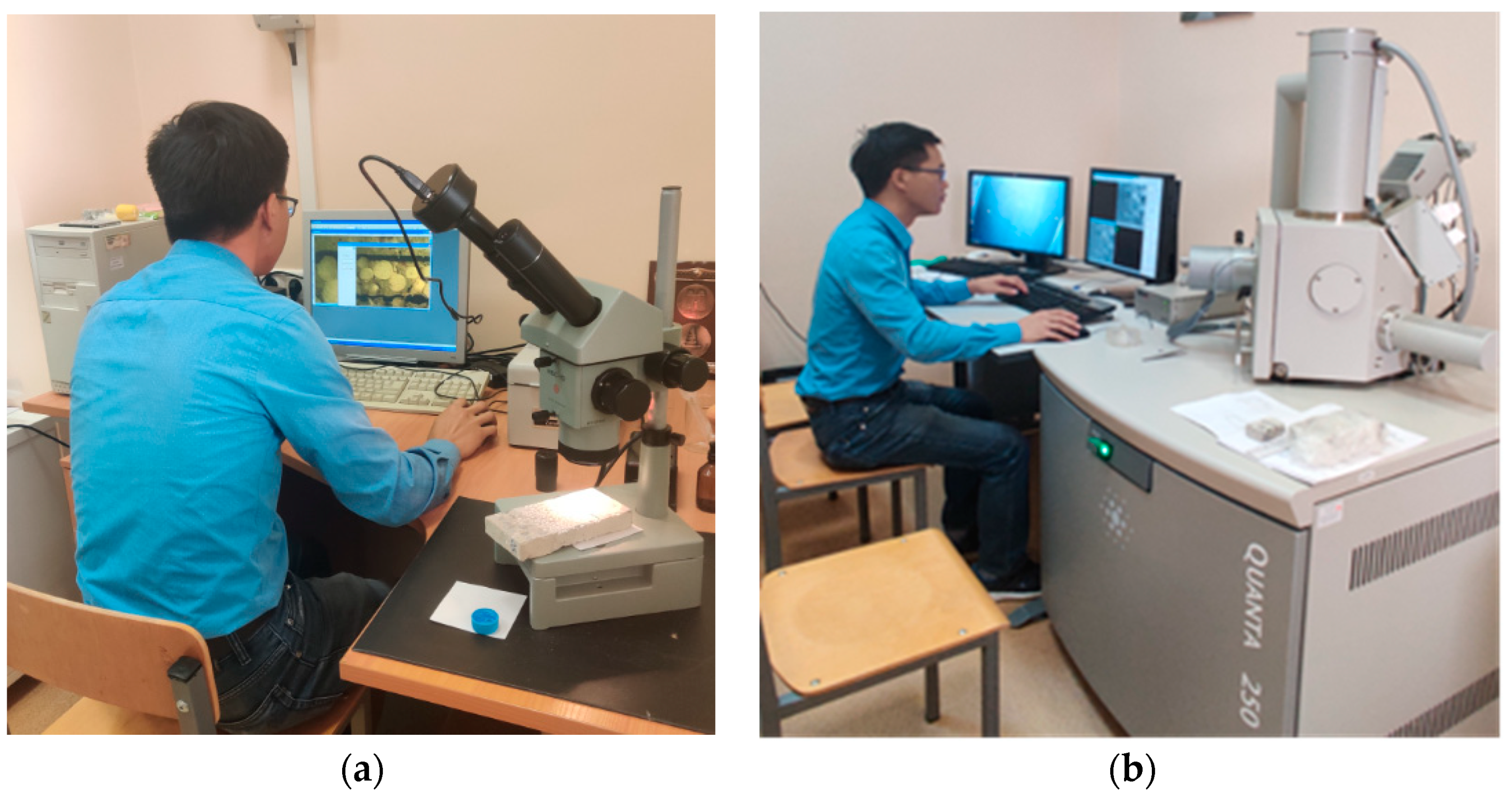
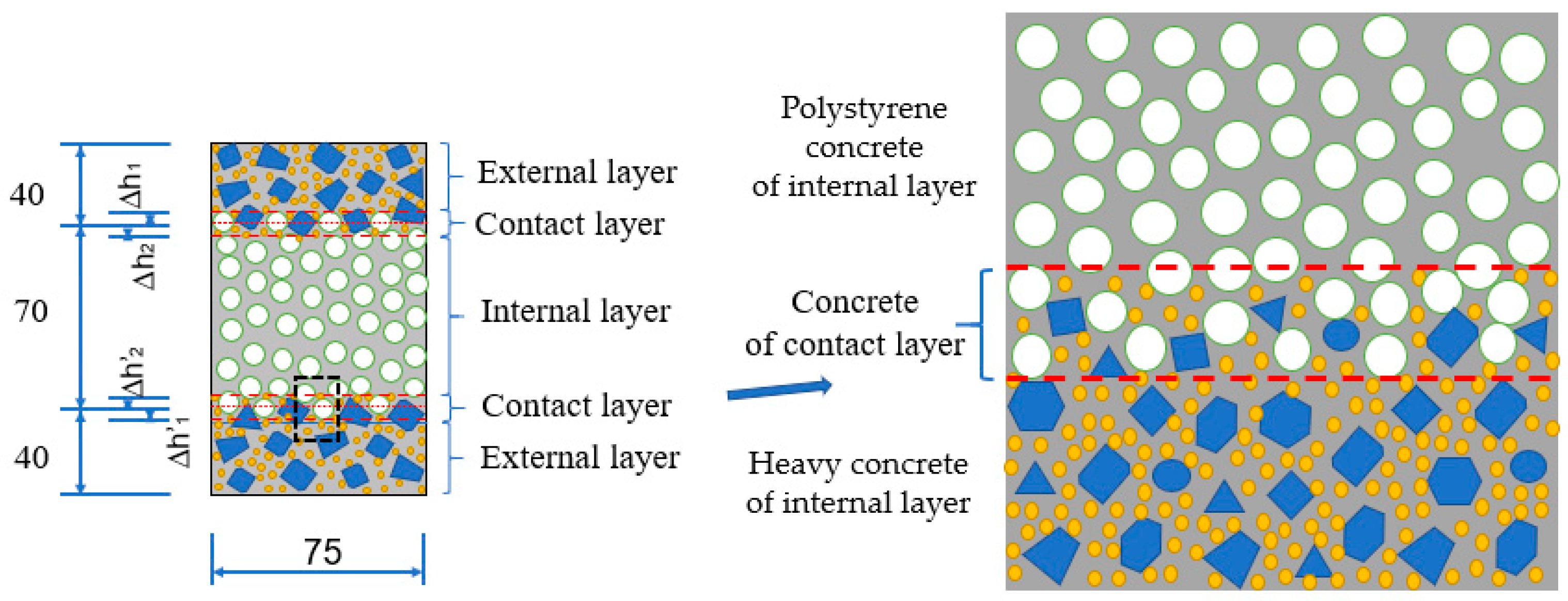
Experiments of microscopic study of the formation and geometric characteristics of the contact zone between layers of various concrete of the external and internal layers were carried out with a stereoscopic microscope MBS10 on three-layer samples of 150 × 75 × 10 mm (Figure 2b and Figure 3a) and a Quanta 250 scanning electron microscope on samples of 40 × 20 × 10 mm (Figure 2c and Figure 3b). These two types of samples were cut from cubical-shaped three-layer samples of 150 × 150 × 150 mm (Figure 2a).

2.2. Development of a Theoretical Model for Calculating Multilayer Reinforced Concrete Structures during Crack Formation

The method to calculate the stress–strain state of flexural multilayer reinforced concrete structures during crack formation with the external layers of the heavy or keramzit concrete with class from B12.5 to B30 and the internal layer of the lightweight thermally insulating concrete was proposed following studies by Yuri Chinenkov, Elena Korol, Marina Berlinova [1,4,7]. Three calculation schemes (A, B, C) were considered (Figure 4, Figure 5 and Figure 6).
(i)
The method of converting the composite cross-section to a homogeneous cross-section T-beam or I-beam was proposed for calculating deformations and stresses of multilayer structures with a heat-insulating layer in the middle cross-section of structures. This design scheme is starting now referred to as scheme A (Figure 4). Scheme A has not taken into account the different values of the compressive and tensile strength of concrete of the external and middle layers in the tensile and compressive zone of the cross-section.
(ii)
The calculation of the formation of the crack normal to the longitudinal axis of multilayer structures is made in Scheme B (Figure 5). Scheme B assumes that before cracks formation, the stresses in the compressed zone’s concrete are determined with the account of elastic deformations, and stresses reach the limit of the tensile resistance of the concrete in the stretched zone. The forces perceived by the normal cross-section in the limiting state before the formation of cracks are determined based on the following provisions:
-
the cross-sections after deformation remains flat, i.e., the deformations in the height of the element change according to Hook’s law;
-
the maximum value of elongation stretched extreme fiber of concrete is equal to 2 R bt E b 1 ;
-
the stress in the concrete compressed zone is determined by the elastic deformation of the concrete in the corresponding layer;
-
the stresses at the boundary line of two concrete layers are different for each concrete layer due to the different modules of elasticity;
-
stress in the concrete stretched zones is evenly distributed within each layer and equal to the axial tensile resistance of the concrete of the external layer s Rbt1 and internal layers Rbt2, respectively;
-
the stresses in the reinforcement are equal to the algebraic sum of the stresses corresponding to the increment of the surrounding concrete’s deformations and the stress.
(iii)
Authors propose Scheme C (Figure 6) for calculating the stress and deformation during crack formation for three-layer reinforced concrete structures, with two contact interlayers between the external and internal layers. The contact interlayers have the thickness h*. It is assumed that, before cracking, the greatest elongation of the tensile concrete fiber is 2 R bt E b 1 . If the thickness of contact interlayers h* is equal to 0, then Scheme C will revert to Scheme B (without accounting for the contact interlayer effect). The properties and characteristics of the contact interlayer’s concrete are designated as: compressive strength Rb*, tensile strength Rbt*, and the modulus of elasticity Eb*; thickness h*.
The results of previous studies [4,7] show that cracks do not appear in the operational stage of multilayer reinforced concrete structures, and tension in the stretched zone does not reach the ultimate tensile strength. The equations for calculating the deformation and stress at the points on the cross-section, shown in scheme C (Figure 6), have the following form:
ε 1 top = ε 0 x h x ;   σ b 1 top = ε 1 top E b 1 = ε 0 x h x E b 1 = 2 R bt 1 x h x ,
ε s = ε 0 x a h x ; σ s = ε s E s + σ shr = 2 R bt 1 E s E b 1 x a h x + σ shr ,
ε top = ε 0 x ( h 1 h 2 ) h x σ b , ext top = σ b , int top = ε top E b 1 = ε 0 x ( h 1 h 2 ) h x E b 1 = 2 R bt 1 x ( h 1 h 2 ) h x
ε 2 top = ε 0 x ( h 1 + h 2 ) h x ; σ b , ext top = σ b 2 , int top = ε 2 top E b 2 = ε 0 x ( h 1 + h 2 ) h x E b 2 = 2 R bt 1 x ( h 1 + h 2 ) h x E b 2 E b 1
ε 2 bot = ε 0 h x ( h 1 + h 2 ) h x ; σ bt 2 , int bot = R bt 2 = σ bt , int bot ,
ε bot = ε 0 x ( h 1 h 2 ) h x ; σ bt , ext bot = R bt 1 = σ bt 1 , int bot ,
ε s = ε 0 h x a h x ; σ s = ε s E s σ shr = 2 R bt 1 E s E b 1 h x a h x σ shr ,
ε 1 bot = ε 0 ; σ bt 1 bot = R bt 1 ,
where: ε b and ε s are the strain of concrete and steel;
  • ε top and ε bot are the strain of materials in the top and bottom layers of the neutral axis;
  • σ b top and σ bt bot are the compressive and tensile stress of concrete in the top and bottom layers of the neutral axis;
  • σ s is the tensile stress of steel;
  • σ shr is the compressive stress by shrinkage of concrete;
  • E b and E s are elastic modulus of the concrete and steel;
  • h 1 is thickness of external layers;
  • b and h are width and height of cross-section;
  • R b 1 , R b 2 and R bt 1 , R bt 2 are the ultimate compressive and tensile stress of concrete in external and internal layers.
From here, the forces perceived by concrete and reinforcement directly before cracking are equal:
N b 1 top = σ b 1 , int top b ( h 1 h 2 ) + 1 2 ( σ b 1 , ext top σ b 1 , int top ) b ( h 1 h 2 )
N b top = σ b 2 , int top bh + 1 2 ( σ b 1 , in t top σ b 2 , int top ) bh
N b 2 top = 1 2 σ b 2 , int top ( x h 1 h 2 ) b
N s = ( ε s E s + σ shr ) A s
N bt 1 bot = R bt 1 b ( h 1 h 2 )
N bt bot = R bt 2 bh + 1 2 ( R bt 1 R bt 2 ) bh
N bt 2 bot = R bt 2 b ( h x h 1 h 2 )
N s = ( ε s E s σ shr ) A s .
The total compression in the cross-section is:
N { top } = N b 1 top + N b top + N b 2 top + N s .
The total stretch in the cross-section is:
N { bot } = N bt 1 bot + N bt bot + N bt 2 bot + N s .
The height of the compressed zone before the formation of cracks is determined from the condition of the balance of external forces and internal forces in the reinforcement and concrete, i.e., N{top} = N{bot}.
( E b 2 E b 1 R bt 2 R bt 1 ) x 2 + ( ( 3 2 E b 2 E b 1 ) ( h 1 h 2 ) + ( 3 2 + R bt 2 2 R bt 1 E b 2 E b 1 ) h + R bt 2 R bt 1 [ 2 h ( h 1 h 2 ) h ] + 2 E s E b 1 ( A s + A s ) b σ shr R bt 1 b ( A s + A s ) ) x + ( ( h 1 h 2 ) 2 h h 1 E b 2 E b 1 h [ ( h 1 h 2 ) + h ] 2 h ( h 1 h 2 ) 1 2 hh ( 1 + R bt 2 R bt 1 ) h R bt 2 R bt 1 [ h ( h 1 h 2 ) h ] + σ shr ( A s + σ shr ) R bt 1 b 2 E s bE b 1 [ A s a + A s ( h a ) ] ) = 0
The height of the compressed zone at the zero line is the solution of the quadratic Equation (19).
The crack propagation moment M{crc} of the flexural three-layers structures made of various concretes consists of the bending moments perceived by the layers of stretching of the stretching zone, including reinforcing steel is:
M { crc } ( M b , i + M s ) + ( M bt , i + M s )
These moments can be calculated following the resulting axial forces acting in the layers of concrete and reinforcing steel and their positions:
M { crc } N ( h y c y c )
The position of the resultant forces of the compressed and stretched zones and the shoulder of the internal pair of forces are determined as:
y c = σ b 1 , int top ( h 1 h 2 ) b ( h 1 h 2 ) 2 + 1 2 ( σ b 1 , ext top σ b 1 , int top ) ( h 1 h 2 ) b ( h 1 h 2 ) 3 + σ b 2 , int top h b ( h 1 h 2 + h 2 ) + 1 2 ( σ b 1 , int top σ b 2 , int top ) h b ( h 1 h 2 + h 3 ) + 1 2 σ b 2 , int top b [ x ( h 1 h 2 ) h ] [ ( h 1 h 2 ) + h + x ( h 1 h 2 ) h 3 ) + 1 2 σ b 2 , int top b ( x h 1 h 2 ) [ ( h 1 h 2 ) + h + ( x h 1 h 2 ) 3 ] + σ s A s 1 a σ b 1 , int top ( h 1 h 2 ) b + 1 2 ( σ b 1 , ext top σ b 1 , int top ) ( h 1 h 2 ) b + σ b 2 , int top h b + 1 2 ( σ b 1 , int top σ b 2 , int top ) h b + 1 2 σ b 2 , int top b [ x ( h 1 h 2 ) h ] + 1 2 σ b 2 , int top b ( x h 1 h 2 ) + σ s A s 1
y c = R bt 1 ( h 1 h 2 ) b ( h 1 h 2 ) 2 + 1 2 ( R bt 1 + R bt 2 ) h b ( ( h 1 h 2 ) + h 3 ) + R bt 2 b ( h x ( h 1 h 2 ) h ) ( ( h 1 h 2 ) + h + h x ( h 1 h 2 ) 2 ) + ( σ s σ shr ) A s a R bt 1 ( h 1 h 2 ) b + 1 2 ( R bt 1 + R bt 2 ) h b + R bt 2 b ( h x ( h 1 h 2 ) h ) + ( σ s σ shr ) A s

2.3. Experiment for Determination of Stress and Deformation of Flexural Three-Layer Reinforced Concrete Beams During Cracking

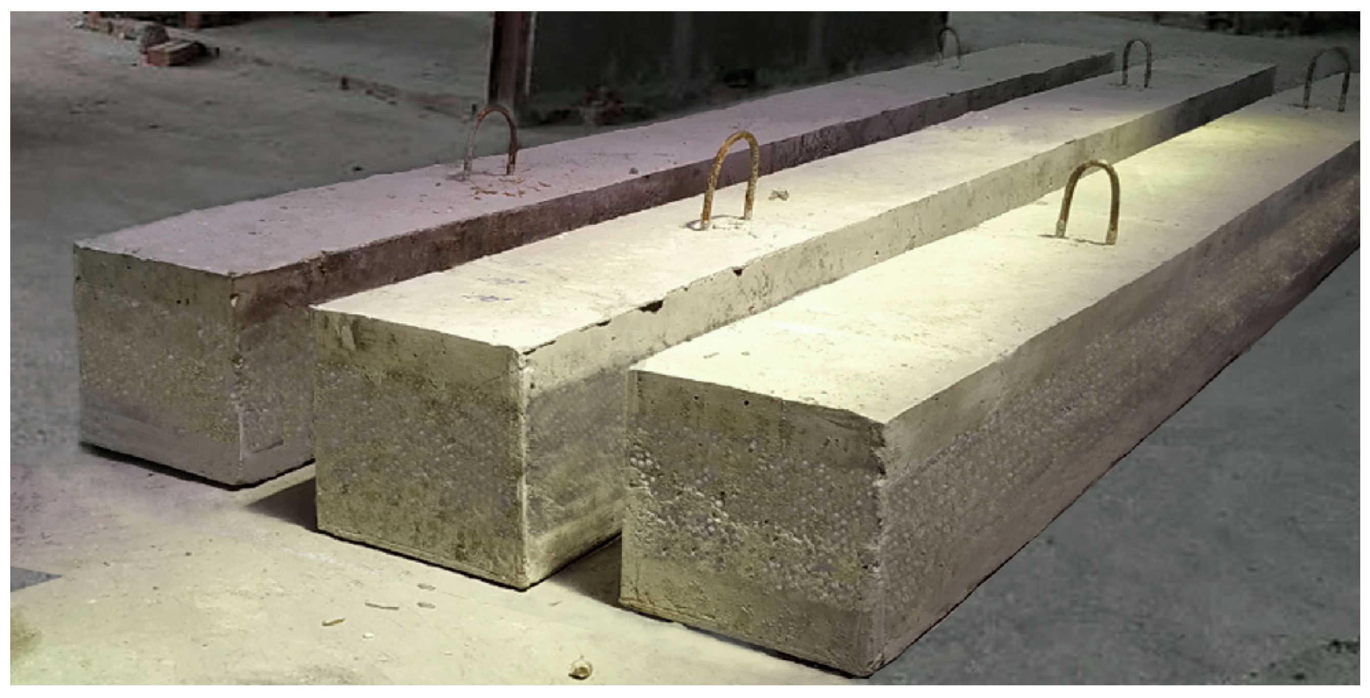
Three samples (B1, B2, B3) were prepared to carry out experimental studies of the stress–strain state of three-layer elements for bending (Figure 7 and Figure 8). The working bar reinforcement of the samples was made of steel of class CIII with a diameter of 8 mm, and shear reinforcement was made of class CI steel with a diameter of 6 mm.
Control samples for determining the strength and deformative characteristics of concretes of the three-layer reinforcement concrete elements were made in metal forms. Table 4 shows the properties of heavy concrete and polystyrene concrete used in the experimental three-layers beams.
Table 5 shows the results of tests that determined the strength and deformative characteristics of the reinforcement on the break of samples.
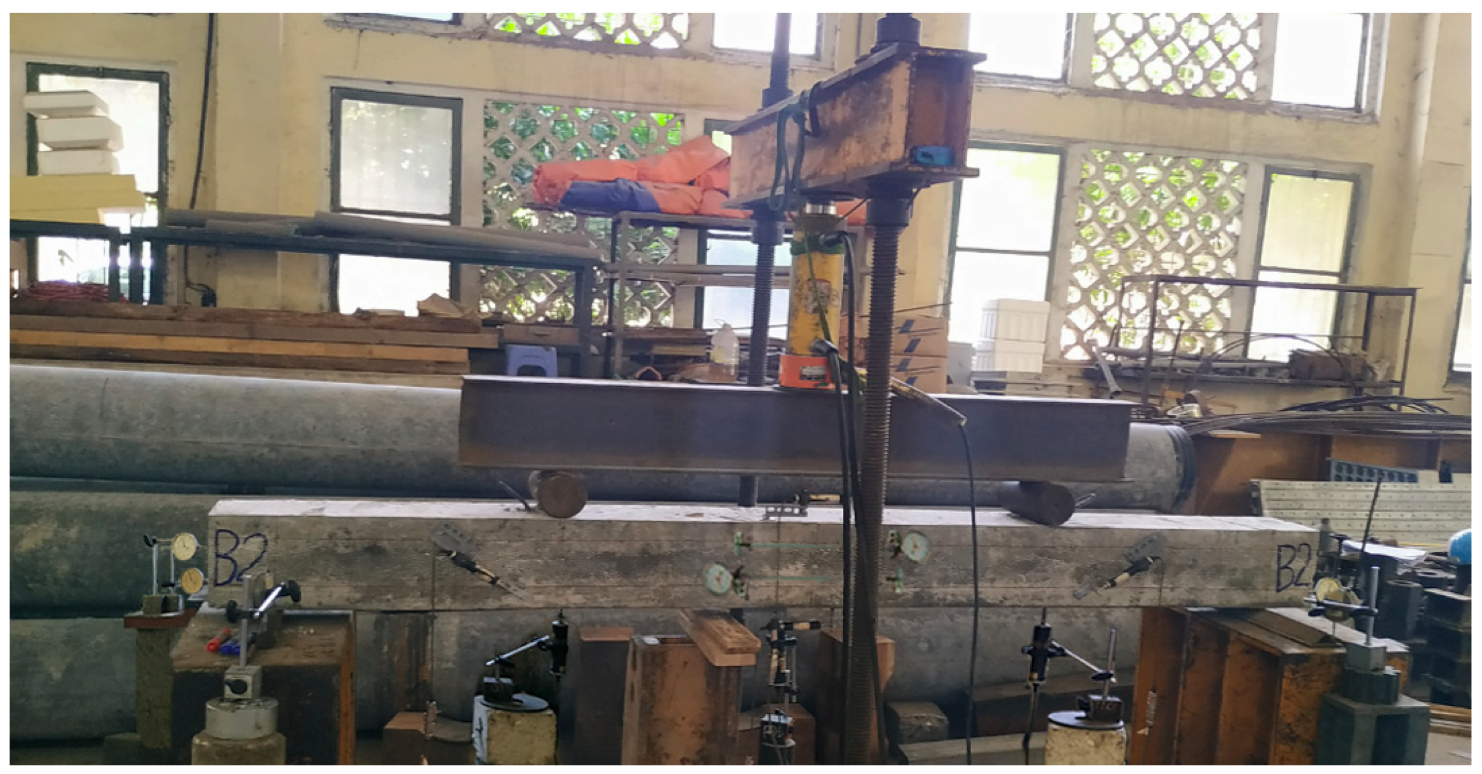
The stand was assembled to test the three-layer elements. Figure 9 shows the general view of the stand. The stand consists of supports located on a fixed trolley, safety racks, a forceful frame in the form of a movable plate, and racks with a screw thread fixed to the forceful floor. Loading of three-layer elements is carried out by a hydraulic jack through a distribution cross-arm in two sections through articulated-movable support. The articulated support is a roller with a diameter of 40 mm, which was enclosed between the support plate and the distribution traverse. An equal-flange corner serves as hinge-fixed support. The base plates were installed on the mortar. The loading of the beam specimens was performed in stages equal to 1/10 of the expected breaking load, with holding at each stage for 10–15 min.
Deformations were measured in the middle of the span at each loading stage to evaluate the stress–strain state of three-layers samples with a monolithic layer bond. Hour-type indicators with graduation of 0.01 mm, with a base of 200 mm, were installed in six levels along the cross-section height to determine the neutral axis’s position and the average relative deformations of the concrete along the cross-section height. Figure 9 shows fragments of the arrangement during the tests located in the middle part and in the three-layer elements’ support zones.
In addition, in the load application places, hour-type indicators with a graduation of 0.001 mm were installed vertically to determine the middle layer’s deformation and at the ends of the three-layer elements. Hour-type indicators with a graduation of 0.01 mm determined the amount of layer displacement.
Deflections of three-layer elements were measured by deflection meters of the system with a graduation of 0.001 mm. They were installed in the center of the span.

3. Results and Discussion

3.1. Test Results of The Study of the Formation and Geometric Characteristics of the Contact Interlayer of Multilayer Reinforced Concrete Structures

The contact zone structure between the external and internal layers of three-layer reinforced concrete structures was observed using an MBS10 panoramic microscope and a Quanta 250 scanning electron microscope. Twelve samples, presented in Section 2.2, were tested in this way.
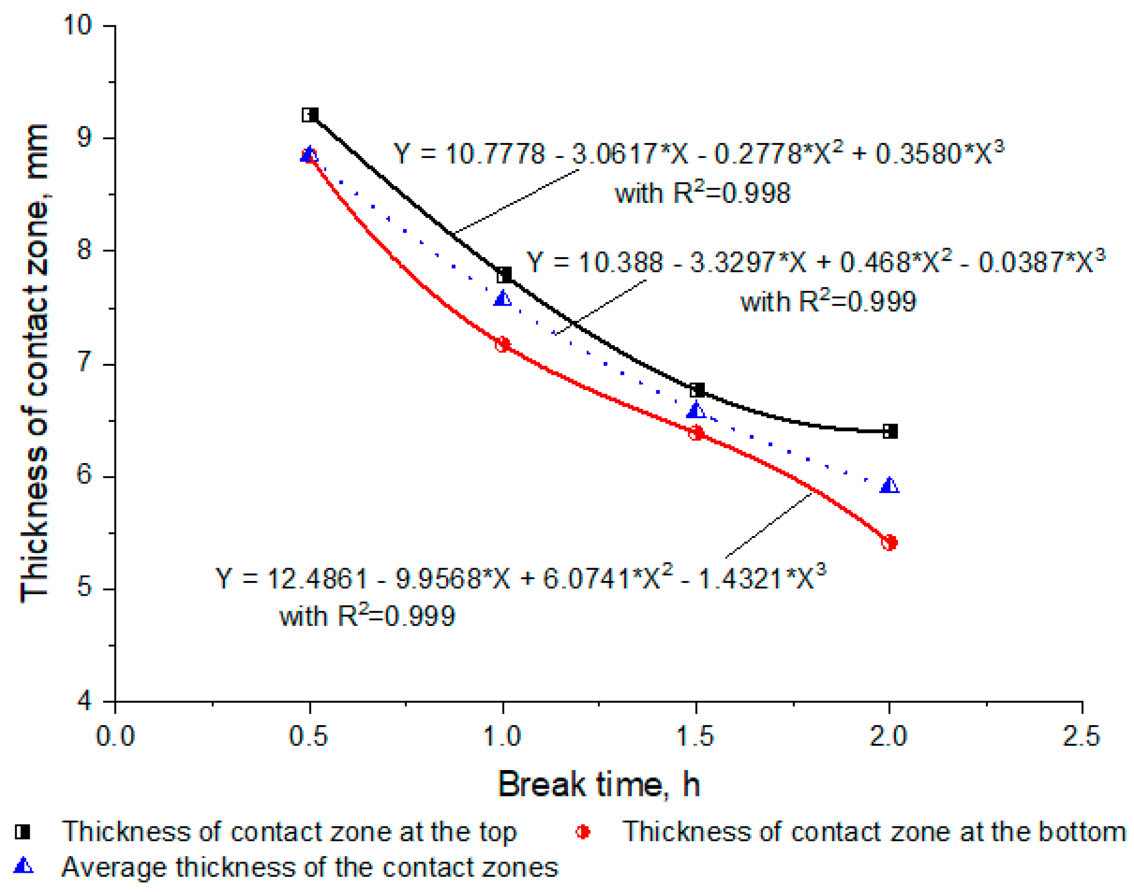
All tested samples are divided into four groups by the time intervals between layers placing into the metal form. These time intervals were varied from 0 min to 2 h with a step of 30 min. The obtained experiment’s results were 12 formations and structures of the contact zone of layers. Table 6 and Figure 10 show the thickness of the contact zone.
Table 6 and Figure 10 show that, if placing successive layers of heavy concrete and polystyrene concrete with the same adhesive material is the type of cement, then the cross-section of the block between the layers of different materials is the monolithic cross-section. The average thickness of the concrete bonding zone between the layers is from 0 to 1 cm, which depends on the manufacturing technology and the break time between the layers’ placing, as well as the size of the aggregate of heavy concrete and polystyrene concrete. If the break time between placing the layers of different concretes decreases, then the contact zone’s thickness between the layers becomes greater.
If the break time between the layers’ placing does not reach the period of hardening of the lower concrete layer, then aggregates and cement mix fresh concrete of the next layer penetrates the concrete area of the previous layer. Moreover, on the contrary, if the break time between the layers’ placing increases, aggregates and cement mixtures of fresh concrete layers penetrate each other less, then the contact zone’s thickness decreases.
Figure 10 shows that, with the same break time between the layers’ placing, the contact zone’s thickness between the external and internal layers in the upper part is greater than in the lower part of the test samples. It is necessary to explain that aggregates from the upper external layer are heavier than internal layers, so they tend to move downward due to gravity. The contact zone thicknesses between the layers at the top and bottom of the test samples vary slightly with short break times, and the difference in the contact zone thicknesses increases with the break time.
The microscopy of the zone between layers of different concretes shows that the contact interlayer between layers is formed due to the penetration of dense coarse and fine aggregates from structural concrete in the adjacent layer of lightweight concrete and inversely, penetration of the aggregate from lightweight concrete in the adjacent layer of structural concrete (Figure 11). The penetration appears if the break time for placing adjacent layers of different concretes does not exceed 2 h. Moreover, no cracks or crevices were observed on the surface of the contact zone between the two layers.
The results of experiments show that the proposed model and the scheme for calculating the flexural multilayer reinforced concrete structures (Figure 6) are consistent with experiments and practice in manufacturing multilayer structures.

3.2. The Calculation of Multilayer Reinforced Concrete Structures with the Contact Interlayer in the Case of Cracking

The calculation of multilayer reinforced concrete structures with the contact interlayer in the case of cracking was performed on sample B-1 of the multilayer reinforced concrete beam with width b = 200 mm, height h = 200 mm, and length l = 2200 mm (Figure 7). Table 5 and Table 6 show the properties of the concretes and reinforcing steel.
The contact interlayer was considered based on the results from Section 3.1. In this problem, the contact interlayers’ height h* varied from 0 to 1 cm. The compressive strength of concrete Rb* varied from Rb2 to Rb1, following the contact interlayer’s position from the boundary between the contact interlayer and the internal layer to the boundary between the contact interlayer and the external layers. Similarly, the values of tensile strength concrete Rbt* and initial modulus of elasticity concrete Eb* varied, respectively, from Rbt2 to Rbt1 and from Eb2 to Eb1.
Table 7 shows the calculated crack propagation moment Mcrc for multilayer reinforced concrete beams. The calculation was made for three computational schemes (see Section 2.2):
(i)
Scheme A of the cross-section conversion (Figure 4) without contact interlayer;
(ii)
Scheme B (Figure 5) without contact interlayer, which earlier was proposed by the authors [1,4,9];
(iii)
The proposed Scheme C (Figure 6) with the contact interlayer.
Table 7 shows that for the same contact interlayer’s thickness in the range 0 to 1 cm, the crack propagation moment in Scheme A and Scheme B without contact interlayer does not change. Still, in Scheme C with the contact interlayer, the crack propagation moment changes to 2.3%.
The crack propagation moment obtained from proposed Scheme C is greater to 2.3% than Scheme A and Scheme B.

3.3. Comparison of Experimental and Calculated Crack Propagation Moment for Multilayer Reinforced Concrete Structures

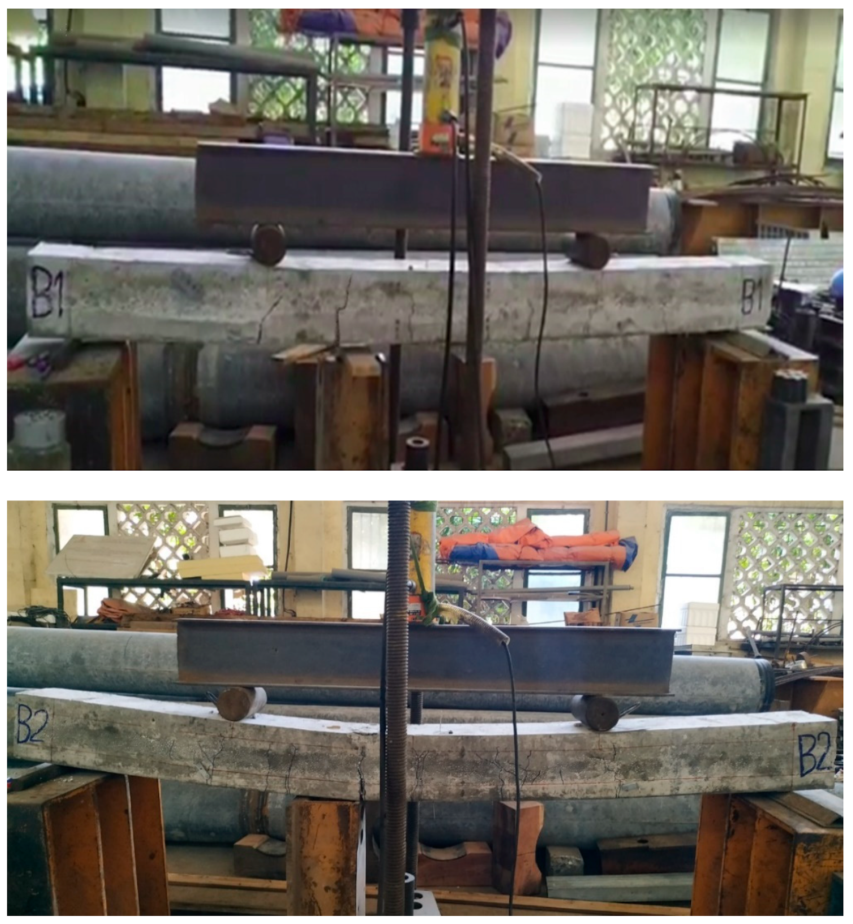
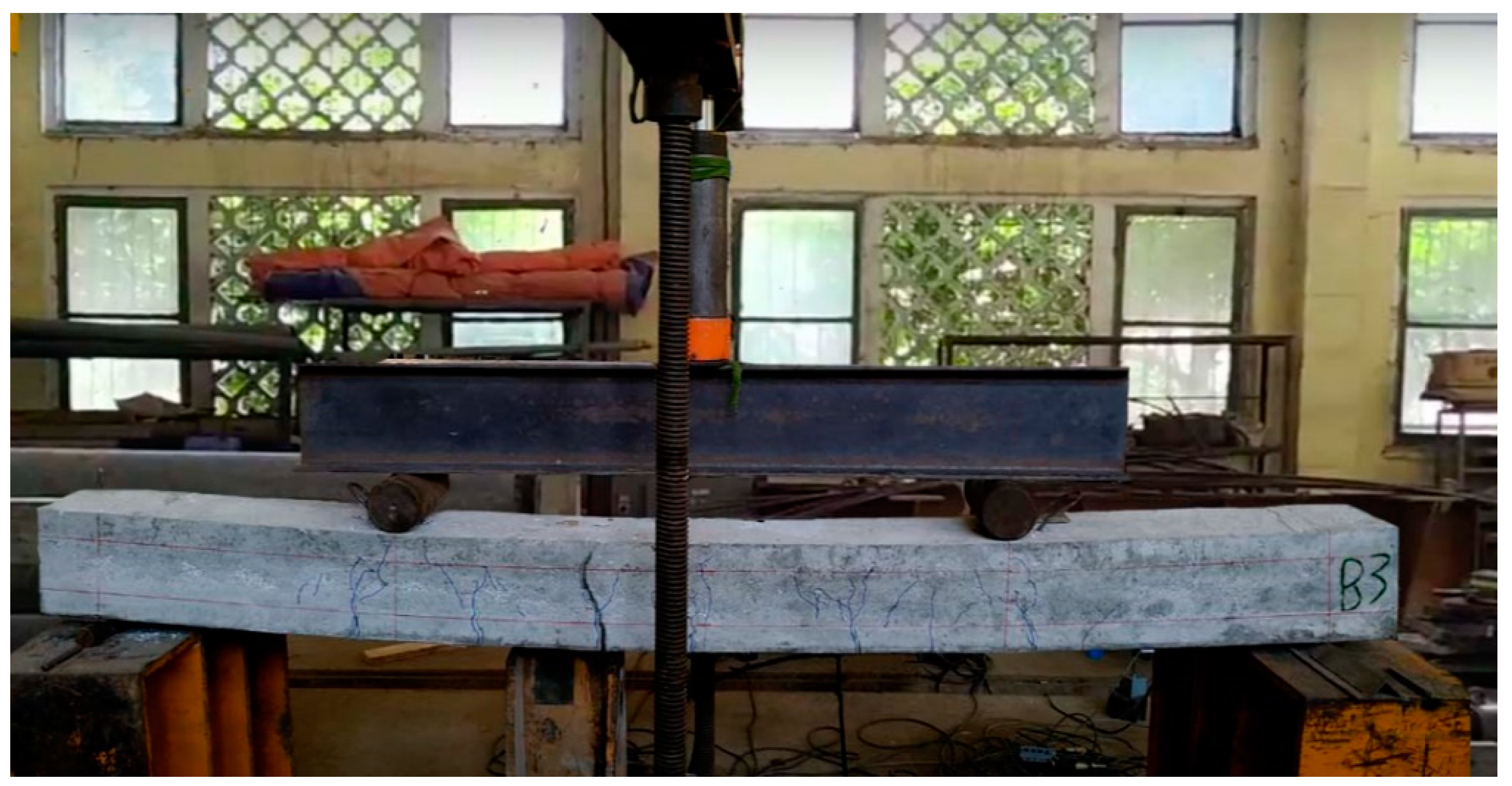
The experimental determination of crack propagation moment for multilayer reinforced concrete structures (Figure 12) was carried out on three beams B1, B2, and B3, the parameters of which are given in Section 2.3. Table 8 shows the comparison of experimental results and calculations.
Table 8 shows that the crack propagation moment from the proposed Scheme C is 2.2% less than that obtained in the experiment and 1.3% greater than that obtained by Scheme A and Scheme B without the contact interlayer. However, the crack propagation moment by the proposed Scheme C is more nearly to experimental results than other theoretical Schemes A and B.

4. Conclusions

The obtained experimental and theoretical results lead to the following conclusions:
(1).
In the manufacturing of reinforced multilayer precast concrete structures with different concrete types in the external and internal layers, a contact interlayer thickness up to 1 cm is formed between them.
(2).
It was shown that the contact interlayers between the external and internal layers improve the structural stability and monolithic cross-section of multilayer reinforced concrete structures.
(3).
The method for calculating the stress–strain states for the three-layer reinforced concrete structure with the contact interlayers between layers of different types of concretes was proposed and developed.
(4).
The results of the calculated crack propagation moment for three-layer reinforced concrete beams by the proposed method with accounting the contact interlayers is 9.1% greater than that obtained by the scheme of the cross-section conversion. These results are near to experimental results than other theoretical models without taking into account the contact interlayer.

Author Contributions

This study was designed, directed, and coordinated by V.D.T. and E.A.K. and N.I.V., as the principal investigator, provided conceptual and methodology for all aspects of the project. V.D.T. and E.A.K. planned and performed experimental studies of the formation of a contact interlayer and analyzed the data of experimental studies. V.D.T. and E.A.K. contributed and proposed the theoretical model for calculating multilayer reinforced concrete structures during crack formation. N.I.V. and H.M.D. planned and performed the experiment for determination of stress and deformation of flexural three-layer reinforced concrete beams. V.D.T. and E.A.K. performed and analyzed the data from the calculation and the experiment for determination of stress and deformation of flexural three-layer reinforced concrete beams with the contact interlayer in the case of cracking. The manuscript was written by V.D.T., E.A.K. and N.I.V. commented on by all authors. All authors have read and agreed to the published version of the manuscript.

Funding

The research is partially funded by the Ministry of Science and Higher Education of the Russian Federation as part of World-class Research Center program: Advanced Digital Technologies (contract No. 075-15-2020-934 dated 17.11.2020).

Institutional Review Board Statement

Not applicable.

Informed Consent Statement

Informed consent was obtained from all subjects involved in the study.

Data Availability Statement

The data presented in this study are available on request from the corresponding author.

Acknowledgments

We express our gratitude: to employees of the department of housing and communal complex, Moscow State University of Civil Engineering, Moscow, Russian Federation, for the help in carrying out research; to employees of the laboratory No-3, Vietnam Institute for Building Science and Technology (IBST), Ha Noi, Viet Nam, for extending support to me in my effort to conduct an experiment.

Conflicts of Interest

All authors declare no conflict of interest about the representation or interpretation of reported research results. The funders had no role in the design of the study; in the collection, analyses, or interpretation of data; in the writing of the manuscript, or in the decision to publish the results.

References

  1. Korol, E.; Tho, V.D.; Hoang, N.H. Analysis of the effectiveness of thermal insulation of a multi-layer reinforced concrete slab using a layer of concrete with low thermal conductivity under the climatic conditions of Vietnam. MATEC Web Conf. 2018, 251, 04026. [Google Scholar] [CrossRef]
  2. Halwatura, R.U.; Jayasinghe, M.T.R. Thermal performance of insulated roof slabs in tropical climates. Energy Build. 2008, 40, 1153–1160. [Google Scholar] [CrossRef]
  3. Santamouris, M. Analyzing the heat island magnitude and characteristics in one hundred Asian and Australian cities and regions. Sci. Total Environ. 2015, 512, 582–598. [Google Scholar] [CrossRef]
  4. Korol, E.; Berlinova, M. Calculation of multilayer enclosing structures with middle layer of polystyrene concrete. MATEC Web Conf. 2018, 193, 03020. [Google Scholar] [CrossRef] [Green Version]
  5. Mavromatidis, L.E.; Michel, P.; El Mankibi, M.; Santamouris, M. Study on transient heat transfer through multilayer thermal insulation: Numerical analysis and experimental investigation. Build. Simul. 2010, 3, 279–294. [Google Scholar] [CrossRef]
  6. Belyaev, A.; Nesvetaev, G.; Mailyan, D. The Issues of Energy-Efficiency Increase of Three-Layer Reinforced Concrete Plate Constructions. Adv. Intell. Syst. Comput. 2018, 692, 529–535. [Google Scholar] [CrossRef]
  7. Tho, V.D.; Kopol, E.A. Influence of contact layers on the crack resistance of bent three-layer structures. Vestn. MGSU 2020, 15, 988–998. [Google Scholar] [CrossRef]
  8. Lam, T.V.; Vu, D.T.; Dien, V.K.; Bulgakov, B.I.; Korol, E.A. Properties and thermal insulation performance of lightweight concrete. Mag. Civ. Eng. 2018, 84, 173–191. [Google Scholar] [CrossRef]
  9. Vilguts, A.; Serdjuks, D.; Pakrastins, L. Design Methods of Elements from Cross-laminated Timber Subjected to Flexure. Procedia Eng. 2015, 117, 10–19. [Google Scholar] [CrossRef] [Green Version]
  10. Korol, E.A. The choice of the rational parameters of three-layer reinforced concrete enclosing structures with the monolithic bond of layers by computer simulation. IOP Conf. Ser. Mater. Sci. Eng. 2018, 456, 012075. [Google Scholar] [CrossRef]
  11. Amran, Y.H.M.; Rashid, R.S.M.; Hejazi, F.; Abang Ali, A.A.; Safiee, N.A.; Bida, S.M. Structural Performance of Precast Foamed Concrete Sandwich Panel Subjected to Axial Load. KSCE J. Civ. Eng. 2017, 22, 1179–1192. [Google Scholar] [CrossRef]
  12. Diamond, S. Aspects of concrete porosity revisited. Cem. Concr. Res. 1999, 29, 1181–1188. [Google Scholar] [CrossRef]
  13. Clouston, P.; Bathon, L.A.; Schreyer, A. Shear and Bending Performance of a Novel Wood–Concrete Composite System. J. Struct. Eng. 2005, 131, 1404–1412. [Google Scholar] [CrossRef] [Green Version]
  14. Fernando, P.L.N.; Jayasinghe, M.T.R.; Jayasinghe, C. Structural feasibility of Expanded Polystyrene (EPS) based lightweight concrete sandwich wall panels. Constr. Build. Mater. 2017, 139, 45–51. [Google Scholar] [CrossRef]
  15. Wu, Z.; Chen, B.; Liu, N. Fabrication and compressive properties of expanded polystyrene foamed concrete: Experimental research and modeling. J. Shanghai Jiaotong Univ. Sci. 2013, 18, 61–69. [Google Scholar] [CrossRef]
  16. Shendy, M.E. A comparative study of LECA concrete sandwich beams with and without core reinforcement. Cem. Concr. Compos. 1991, 13, 143–149. [Google Scholar] [CrossRef]
  17. Shams, A.; Horstmann, M.; Hegger, J. Experimental investigations on Textile-Reinforced Concrete (TRC) sandwich sections. Compos. Struct. 2014, 118, 643–653. [Google Scholar] [CrossRef]
  18. Aydogdu, M. Vibration analysis of cross-ply laminated beams with general boundary conditions by Ritz method. Int. J. Mech. Sci. 2005, 47, 1740–1755. [Google Scholar] [CrossRef]
  19. Andreev, V.I.; Turusov, R.A.; Tsybin, N.Y. Application of the Contact Layer in the Solution of the Problem of Bending the Multilayer Beam. Procedia Eng. 2016, 153, 59–65. [Google Scholar] [CrossRef]
  20. Turusov, R.A.; Andreev, V.I.; Tsybin, N.Y. The contact layer stiffness influence assessment on the stress-strain state of a multilayer beam. Architecture, design and reconstruction of architectural heritage (2020). IOP Conf. Ser. Mater. Sci. Eng. 2020, 913. [Google Scholar] [CrossRef]
  21. Gara, F.; Ragni, L.; Roia, D.; Dezi, L. Experimental behaviour and numerical analysis of floor sandwich panels. Eng. Struct. 2012, 36, 258–269. [Google Scholar] [CrossRef]
  22. Tho, V.D.; Korol, E.A. Influence of geometrical parameters of the cross section, strength and deformability of the materials used on stressstrain state of three-layered reinforced concrete. IOP Conf. Ser. Mater. Sci. Eng. 2019, 661, 012121. [Google Scholar] [CrossRef]
  23. Benayoune, A.; Samad, A.; Trikha, D.N.; Ali, A.A.; Ellinna, S.H.M. Flexural behaviour of pre-cast concrete sandwich composite panel—Experimental and theoretical investigations. Constr. Build. Mater. 2008, 22, 580–592. [Google Scholar] [CrossRef]
  24. Gara, F.; Ragni, L.; Roia, D.; Dezi, L. Experimental tests and numerical modelling of wall sandwich panels. Eng. Struct. 2012, 37, 193–204. [Google Scholar] [CrossRef]
  25. Yue, Z.; Xiao, H. Generalized Kelvin Solution based boundary element method for crack problems in multilayered solids. Eng. Anal. Bound. Elem. 2002, 26, 691–705. [Google Scholar] [CrossRef]
  26. Marčiukaitis, G.; Juknevičius, L. Influence of the Internal Layer Cracks on the Cracking of Flexural Three-Layer Concrete Members. J. Civ. Eng. Manag. 2002, 8, 153–158. [Google Scholar] [CrossRef]
  27. Olmedo-Zazo, F.I.; Carrillo-Alonso, L.; Valivonis, J.; Martínez-Pérez, I. Influence of the construction processing the multilayer lightweight concrete beam behaviour. Dyna 2019, 94, 395–400. [Google Scholar] [CrossRef]
  28. Horska, A.; Fladr, J.; Kohoutkova, A. Testing of multi-layer concrete-based structures loaded by contact blast. In Proceedings of the 12th fib International Phd Symposium in Civil Engineering, Czech Technical University in Prague, Prague, Czech Republic, 29–31 August 2018; pp. 427–432. [Google Scholar]
  29. Gao, Y.; De Schutter, G.; Ye, G.; Tan, Z.; Wu, K. The ITZ microstructure, thickness and porosity in blended cementitious composite: Effects of curing age, water to binder ratio and aggregate content. Compos. Part B Eng. Struct. 2014, 60, 1–13. [Google Scholar] [CrossRef]
  30. Hilal, A.A. Microstructure of Concrete. High Perform. Concr. Technol. Appl. 2016. [Google Scholar] [CrossRef] [Green Version]
  31. Andreev, V.I.; Turusov, R.A.; Tsybin, N.Y. The contact layer method in calculating of the shear compounds. RSP 2017–26th R-S-P Seminar 2017 Theoretical Foundation Civil Engineering. MATEC Web Conf. 2017, 117. [Google Scholar] [CrossRef] [Green Version]
  32. Kolchunov, V.I.; Dem’yanov, A.I. The modeling method of discrete cracks and rigidity in reinforced concrete. Mag. Civ. Eng. 2019, 88, 60–69. [Google Scholar] [CrossRef]
  33. Tsybin, N.; Turusov, R.; Andreev, V.; Kolesnikov, A. Stress-strain state of a three-layer rod. Comparison of the results of analytical and numerical calculations with the experiment. MATEC Web Conf. 2018, 196, 01057. [Google Scholar] [CrossRef]
  34. Morozov, N.F.; Tovstik, P.Y. Bending of a two-layer beam with non-rigid contact between the layers. J. Appl. Math. Mech. 2011, 75, 77–84. [Google Scholar] [CrossRef]
  35. Foraboschi, P. Three-layered plate: Elasticity solution. Compos. Part B Eng. 2014, 60, 764–776. [Google Scholar] [CrossRef]
  36. Hadi, M.N.S.; Bodhinayake, B.C. Non-linear finite element analysis of flexible pavements. Adv. Eng. Softw. 2003, 34, 657–662. [Google Scholar] [CrossRef]
  37. Carrera, E. A refined multilayered finite-element model applied to linear and non-linear analysis of sandwich plates. Compos. Sci. Technol. 1998, 58, 1553–1569. [Google Scholar] [CrossRef]
  38. Korolev, A.S.; Zyrianov, F.A. Layer model of the cement composites deformation in the reinforced masonry structures. Constr. Unique Build. Struct. 2020, 92, 9202. [Google Scholar] [CrossRef]
  39. Korolev, A.; Mishnev, M.; Zherebtsov, D.; Vatin, N.I.; Karelina, M.; Arjmand, M. Polymers under Load and Heating Deformability: Modelling and Predicting. Polymer 2021, 13, 428. [Google Scholar] [CrossRef]
  40. Laskar, S.M.; Reja, H.; Talukdar, S. Behaviour of cold jointed and layered Portland cement–alkali-activated reinforced concrete beams. Asian J. Civ. Eng. 2020, 21, 1193–1204. [Google Scholar] [CrossRef]
  41. Lassnig, A.; Putz, B.; Hirn, S.; Többens, D.M.; Mitterer, C.; Cordill, M.J. Adhesion evaluation of thin films to dielectrics in multilayer stacks: A comparison of four-point bending and stressed overlayer technique. Mater. Des. 2021, 200, 109451. [Google Scholar] [CrossRef]
  42. Funari, M.F.; Spadea, S.; Fabbrocino, F.; Luciano, R. A Moving Interface Finite Element Formulation to Predict Dynamic Edge Debonding in FRP-Strengthened Concrete Beams in Service Conditions. Fibers 2020, 8, 42. [Google Scholar] [CrossRef]
  43. Funari, M.F.; Greco, F.; Lonetti, P. A cohesive finite element model based ALE formulation for z-pins reinforced multilayered composite beams. Procedia Struct. Integr. 2016, 2, 452–459. [Google Scholar] [CrossRef] [Green Version]
  44. Funari, M.F.; Lonetti, P. Initiation and evolution of debonding phenomena in layered structures. Theor. Appl. Fract. Mech. 2017, 92, 133–145. [Google Scholar] [CrossRef]
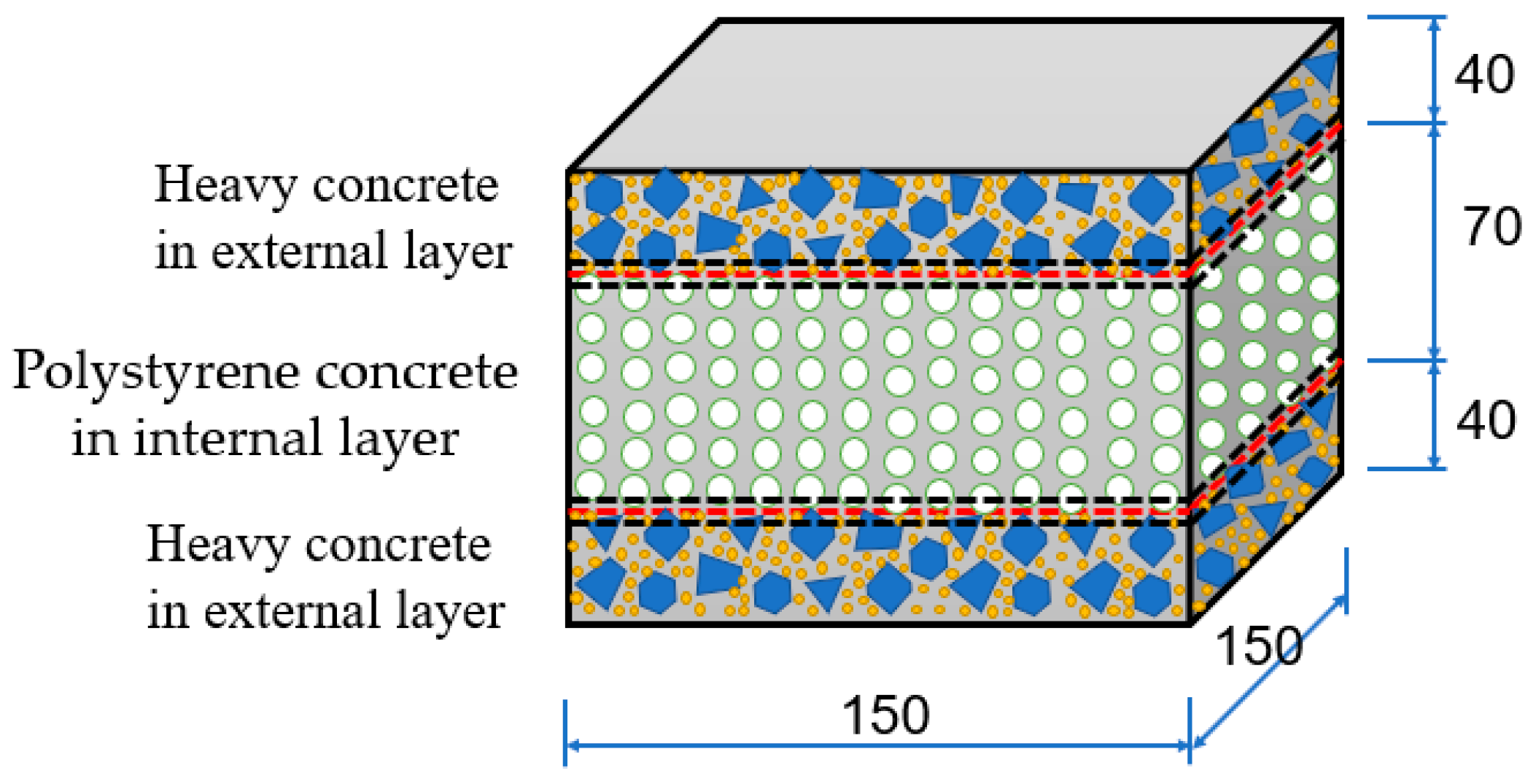
Figure 1. The scheme of 150 × 150 × 150 mm cubical-shaped sample.
Buildings 11 00088 g001
Figure 2. The samples for experiments of the formation and geometric characteristics of the contact interlayer between layers: (a) The cubic three-layer samples 150 × 150 × 150 mm; (b) The samples 150 × 75 × 10 mm for experiment’s stereoscopic microscope MBS10; (c) The samples 40 × 20 × 10 mm for experiment’s scanning electron microscope Quanta 250.
Buildings 11 00088 g002
Figure 3. The experiments of the formation and geometric characteristics of the contact zone between layers with the stereoscopic microscope MBS10 (a) and Quanta 250 (b).
Buildings 11 00088 g003
Figure 4. The calculation scheme A for the distribution of deformations, stresses, and forces in the three-layer with converting the composite section to the homogeneous section.
Buildings 11 00088 g004
Figure 5. The calculation scheme B for the distribution of deformations, stresses, and forces in the three-layer without considering the contact interlayers [1].
Buildings 11 00088 g005
Figure 6. The calculation scheme C for the distribution of deformations, stresses, and forces in the three-layer, taking into account the contact interlayers.
Buildings 11 00088 g006
Figure 7. The schema of the tested beam in bending.
Buildings 11 00088 g007
Figure 8. The samples of the tested beam in bending.
Buildings 11 00088 g008
Figure 9. The scheme of the layout instruments for bending testing.
Buildings 11 00088 g009
Figure 10. The dependence of the thickness of the contact zone on the break time.
Buildings 11 00088 g010
Figure 11. Bonding of the contact zone of layers of multilayer reinforced concrete structures.
Buildings 11 00088 g011
Figure 12. Views of the destruction of the tested beam samples.
Buildings 11 00088 g012aBuildings 11 00088 g012b
Table 1. Composition of concrete mixtures.
Class of ConcreteDensity,
kg/m3
Cement (M400),
kg
Water,
l
Crushed Limestone, from 0.5 to 1 cm in Size,
kg
Sand, from 0 to 2 mm in Size,
kg
Expanded Polystyrene Granules EPS, from 2 to 5 mm in Size,
kg
Chemical Additives, SilkRoad SR-5000F,
g
B1346330105 --0.69710
B2523764391951121621--
Table 2. The properties of heavy concrete.
Density,
kg/m3
Compressive Strength at Different Ages of Hardening, MPaUltimate Tensile Strength in Bending at the Age of 28 Days, MPaAverage Thermal Conductivity
Dry, W/(m °C)
1 Day3 Days7 Days14 Days28 Days
237610.5617.3020.9624.7133.153.291.25
Table 3. The properties of polystyrene concrete.
Density,
kg/m3
Compressive Strength at Different Ages of Hardening, MPaUltimate Tensile Strength in Bending at the Age of 28 Days, MPaAverage Thermal Conductivity
Dry, W/(m °C)
1 Day3 Days7 Days14 Days28 Days
3460.370.450.630.750.830.290.135
Table 4. Strength and deformative characteristics of concrete in experimental beams.
No
of Beams
Heavy ConcretePolystyrene Concrete
RmRbRbtEb·10−3RmRbRbtEb·10−3
MPa
1, 2, 333.1518.062.5633.20.830.750.230.57
Table 5. Strength and deformative characteristics of steel in experimental beams.
No
of Beams
Diameter and Class of SteelAs, cm2fy, MPafu, MPaEs 103,
MPa
1–3Ø8 C-III0.503390563206
Table 6. Thickness of the contact zone, mm.
Series of SamplesLocation of the Contact ZoneThickness of Part Contact Zones for SamplesAverage Thickness of the Contact Zone Section, mmAverage Thickness of the Contact Zone, mm
123 Δ h i ¯ h*
0.5Top∆h14.55.05.54.54.74.94.04.54.54.89.5
∆h24.54.94.74.54.44.15.04.54.54.7
Bottom∆h1’3.64.15.04.84.54.24.35.35.34.79.2
∆h2’4.44.44.13.94.34.14.34.54.74.5
1Top∆h13.63.43.43.94.04.04.23.82.93.98.1
∆h23.94.24.33.94.04.04.24.54.54.2
Bottom∆h1’4.34.03.83.63.53.53.84.24.23.97.6
∆h2’3.33.33.23.94.04.13.53.33.43.7
1.5Top∆h13.53.02.93.43.63.43.33.23.13.36.8
∆h23.84.03.93.33.43.63.33.23.13.5
Bottom∆h1’3.43.13.73.33.33.93.13.43.33.46.4
∆h2’3.03.13.23.33.33.43.13.23.23.2
2Top∆h13.03.13.33.33.23.33.42.82.23.06.3
∆h23.03.13.13.13.23.33.44.04.53.3
Bottom∆h1’2.82.72.62.62.52.82.72.72.82.75.5
∆h2’2.32.72.92.32.22.03.33.63.72.8
Δ h i ¯ = n Δ h i n Average thickness of the contact zone section, mm
h = Δ h 1 + Δ h 2 Average thickness of the contact zone, mm
Table 7. The crack propagation moment Mcrc of multilayer beams.
Thickness of Contact Interlayers, h*, cm The Crack Propagation Moment, Mcrc × 10−4, kN m
Scheme A
(Mcrc{A})
Scheme B
(Mcrc{B})
Scheme C
(Mcrc{C})
%(Mcrc{B})
/(Mcrc{A})
%(Mcrc{C})
/(Mcrc{A})
%(Mcrc{C})
/(Mcrc{B})
04.3514.6724.672107.40%107.40%100.00%
0.14.3514.6724.683107.40%107.65%100.23%
0.24.3514.6724.694107.40%107.90%100.47%
0.34.3514.6724.705107.40%108.15%100.70%
0.44.3514.6724.716107.40%108.40%100.93%
0.54.3514.6724.727107.40%108.66%101.16%
0.64.3514.6724.737107.40%108.91%101.40%
0.74.3514.6724.748107.40%109.16%101.63%
0.84.3514.6724.759107.40%109.41%101.87%
0.94.3514.6724.770107.40%109.66%102.10%
14.3514.6724.781107.40%109.91%102.33%
Table 8. The experimental and calculated crack propagation moment.
No the SamplesName of Beam SamplesThe Crack Propagation Moment, Mcrc × 10−4, kN m
The Results of the TestThe Average Values of the TestBy Using
the Scheme A
(Mcrc{A})
By Using
the Scheme B
(Mcrc{B})
By Using the Proposed Scheme C
(Mcrc{C})
Mcrc{exp}Mcrc{A}%(Mcrc{A}) /Mcrc{exp}Mcrc{B}%(Mcrc{B}) /Mcrc{exp}Mcrc{C}%(Mcrc{C})
/Mcrc{exp}
1B-14.814.844.3589.88%4.6796.50%4.7197.31%
2B-24.834.3589.88%4.6796.50%4.7397.73%
3B-34.884.3589.88%4.6796.50%4.7698.34%
Publisher’s Note: MDPI stays neutral with regard to jurisdictional claims in published maps and institutional affiliations.