1. Introduction
Lightweight Steel-Gauge Frame wall systems are one of the popular types of walling systems in the construction industry nowadays [
1]. The higher strength to weight ratio related to cold-formed steel structures leads to lighter structures resulting in significant savings in construction time, transportation costs, and labour requirements. A considerable part of the LSF wall system is completed at a warehouse or factory, where the wall panels, floor panels and all the components are prefabricated separately. Due to this, waste generation at the construction site is reduced, and the waste generated at the factories could be conveniently forwarded for recycling. Moreover, accurate design and construction of LSF walls and floor systems are possible at the pre-fabrication stage to obtain better quality assurance, reducing the labour requirement. Many studies are being conducted to make LSF wall systems more effective and efficient in various aspects such as structural performance, energy performance, fire performance, cost implications, and sustainability [
2,
3,
4,
5,
6,
7,
8].
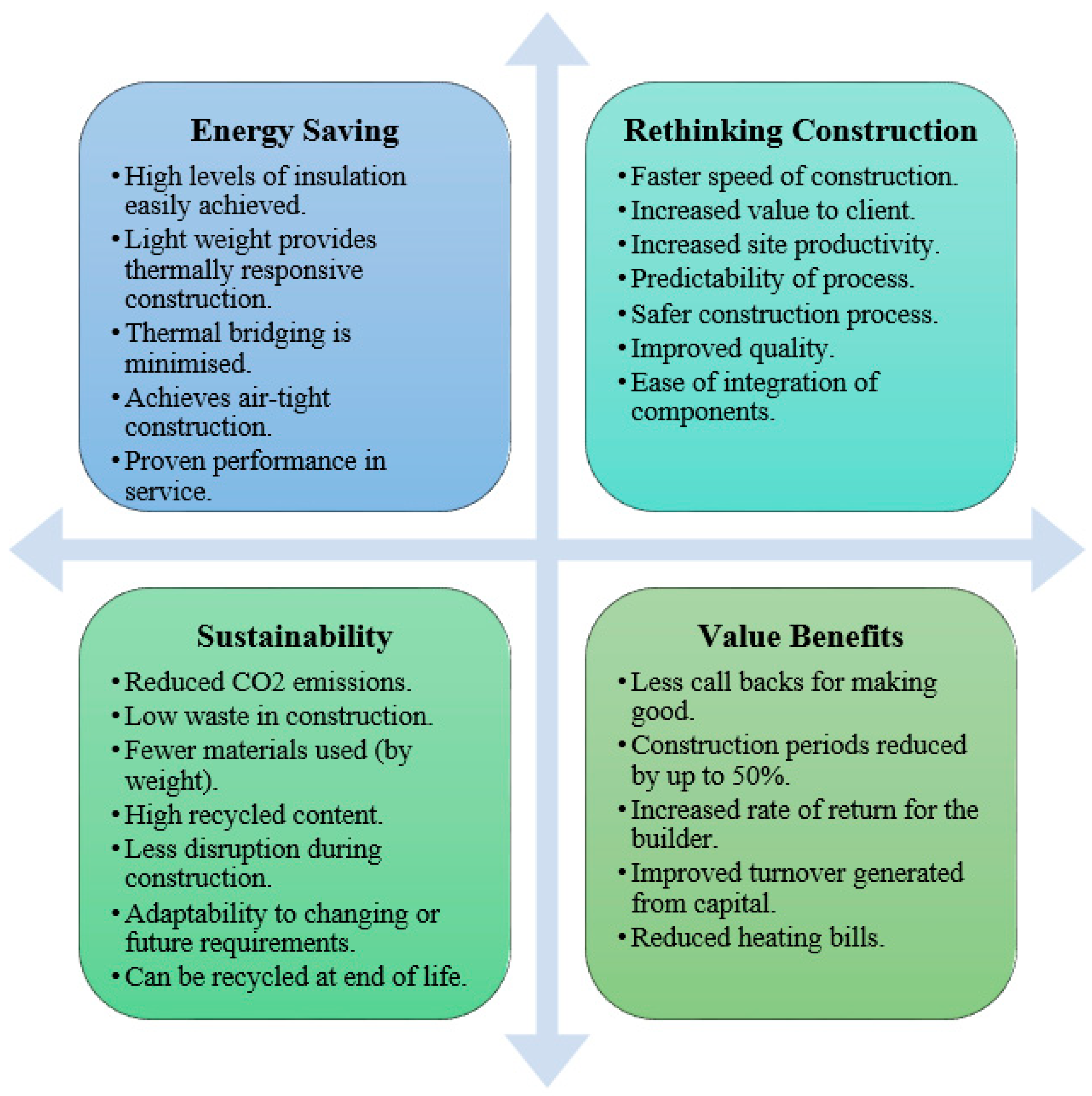
Figure 1 illustrates the benefits of LSF wall systems in the construction industry under different aspects [
9].
Despite all these favourable influences of LSF constructions, there are several drawbacks related to these cold-formed steel structures. Due to the low heat capacities of cold-formed steel members and high thermal conductance, the energy loss of construction in cold climates is critical [
7,
10]. Since the heat transfer rate through LSF wall and floor panels can be much higher than in traditional (brickwork and concrete) construction, the energy requirement of the building throughout its life cycle would be much higher. The increased energy requirements lead to higher building operational costs and poor performance in terms of sustainability criteria. Hence, it is essential to address this poor energy performance inherent in cold-form steel structures and provide adequate thermal insulation following correct design guidelines.
Enhancing the energy efficiency of buildings and developing innovative technological strategies to improve the energy performance of buildings is essential since buildings account for 40% of energy demand and 36% of Carbon dioxide emissions in Europe [
11,
12,
13]. The demand for energy efficiency in buildings and the use of recyclable products has risen in recent decades due to the imperative to create a more sustainable future [
9,
14,
15,
16,
17,
18,
19]. The European Union (EU) identified multiple targets in the Energy Performance Building Directive for the year 2020, including “nearly zero-energy buildings” [
11,
12,
13,
20]. On 15 January 2020, the European Parliament approved the green deal to ensure the EU’s climate neutrality in accordance with the Paris Agreement by 2050, aiming at a net-zero greenhouse gas emissions target [
11]. Throughout a building’s existence, the operational energy (the energy necessary to run the structure) considerably outweighs the embodied energy (the energy necessary to create the structure’s component elements). Over a 60-year design life, the operational energy of an air-conditioned office building is between 5 and 10 times larger than the embodied energy [
6]. By reducing the amount of operating energy required by structures, building designers may greatly influence energy usage [
6]. Ambient conditioning, space heating, and cooling are all emerging trends in buildings, owing to people’s rising need for comfort. Because of their large, exposed surface, the external walls are considered one of the most critical components of heat loss in a structure. Improving the thermal performance of the building envelope is critical for ensuring building energy efficiency. Establishing new external wall solutions that increase thermal efficiency and achieve nearly zero-energy building targets is vital.
LSF walls consist of cold-formed steel studs, joists, and other elements. Therefore, the thermal conductivity of the wall panels would be much higher than traditional constructions unless proper insulation material and designs are used. At the same time, in countries like the UK, the cold climate conditions cause the energy requirements to increase drastically if the heat transfer rates through walls and ceilings are high. Therefore, this study intends to investigate the thermal performance of LSF walls using numerical analysis and accommodate the most appropriate LSF wall design according to UK building regulations. Applicability and effect of novel insulation panel Vacuum Insulation Panel (VIP), effects of its position, and the effect of VIP with traditional insulation material rockwool to the thermal performance are investigated using 112 numerical models. The U-value of each LSF wall was compared and contrasted to determine the better LSF wall assembly based on their thermal performance. Effect of internal insulation thickness, the effect of VIP panel, its thickness and its position to the U-value of the overall LSF configuration was analysed using FE modelling, and optimum LSF arrangements were suggested based on the UK building regulations.
2. LSF Wall Types
Three basic façade LSF wall types can be identified in the construction industry concerning the position of the insulation material; namely, cold-frame, warm-frame, and hybrid-frame constructions, as presented in
Figure 2 [
21]. The cold-frame construction includes the whole volume of thermal insulation inside the cavity to use flexible insulation material. The insulation is discontinuous as the frame elements resulting heat transfer through the frame structure to remain undisturbed by the insulation layer. Due to this discontinuous insulation design and the contacts between different material types incorporated with cold-frame LSF walls, condensation, dampness, and mould growth issues are very common when exposed to different climatic conditions with seasonal changes [
22]. The steel stud temperatures of the cold frame construction would be significantly closer to the exterior temperatures, causing interstitial condensation, ultimately resulting in the appearance of pathologies on the inner side of the walls. With all these undesirable issues related to cold frame construction, it appears to be the least desirable option for a façade wall in cold climates. However, it should also be noted that cold frame is the thinnest wall construction type possible. The whole insulation volume is integrated inside the cavity. Hence, architecturally and in the industry practice, this might be a driving force to encourage cold frame constructions.
On the contrary to cold-frame construction, warm-frame LSF wall construction consists of a rigid thermal insulation layer utterly external to the cold-formed steel studs. This configuration is exceptionally advantageous to the energy performance of the building as the effect of thermal insulation has not been disturbed by the steel section, as shown in
Figure 2. Therefore, in terms of the energy efficiency of the whole construction, warm-frame type façade walls could be identified as the most favourable option. This configuration has the least issues related to condensation, damp and mould growth compared to other types [
21,
22]. However, the thickness of this construction is much higher, which could be a drawback in terms of architectural aspects. Meanwhile, since the insulation layer is exposed to the exterior environment, degradation of material causing durability concerns depends on the climate conditions and the protection layer on the outer side. Therefore, although warm frame construction seems to be appreciable in terms of energy performance, proper measures should be taken to address the durability aspects.
Hybrid-frame construction is a combination of the former two types, where thermal insulation is partly inside the cavity, as in cold-frame type and the rest external to the steel studs as in warm-frame type. Hence, the hybrid-frame LSF wall construction inherits the pros and cons of both cold-frame and warm-frame constructions. However, similar thermal performance with the lower thickness could be obtained in hybrid-frame compared to the warm frame. Therefore in this study, hybrid frame LSF wall systems were considered to investigate the thermal performance.
3. Thermal Bridge Effect in LSF
Due to the high thermal conductivity of steel, heat transfer through steel sections is comparatively higher than the heat transfer through wallboard, thermal insulation, and other components. Therefore, energy loss due to heat dissipation through steel sections would be significant during cold climate conditions [
7]. This phenomenon is referred to as the ‘thermal bridging effect’. When applying the LSF construction techniques in cold climate prone situations, the thermal bridging effect of steel must be appropriately addressed to develop energy-efficient solutions. Although the thermal bridging effect occurs in steel studs in warm frame construction, the heat transferred through the steel section has a thermal insulation barrier to heat dissipation. In hybrid-frame construction also, there is the effect of thermal insulation barrier applied in series with the steel sections. However, in cold-frame construction, thermal insulation is applied only parallel to the steel sections, resulting in a high volume of heat dissipation. Therefore, at the design stage of LSF wall/ floor panels, understanding the application of thermal insulation in series with these thermal bridges can positively influence the construction’s thermal behaviour and energy efficiency.
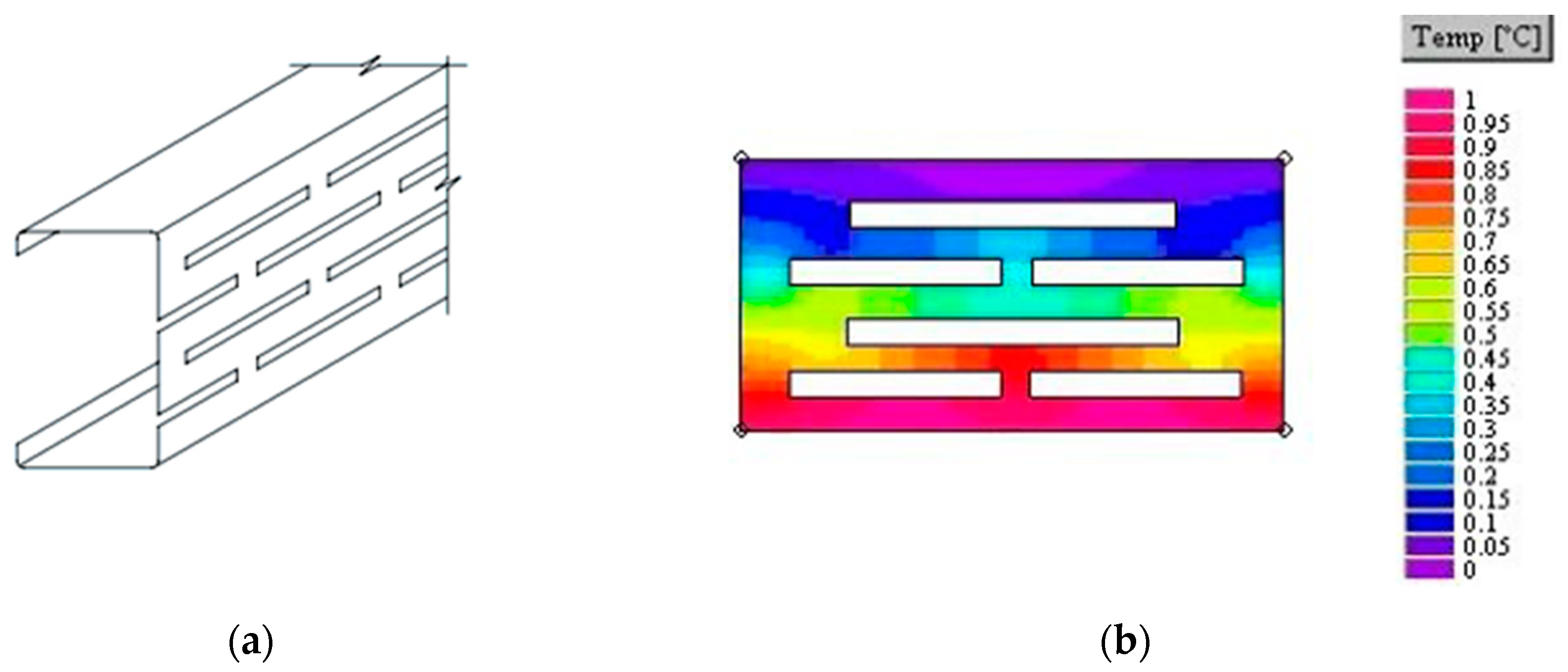
Thermal bridge thermal transmittance can be minimised by employing thermal breaks, modifying the details, or utilising alternative materials. Forming slots in the web of a steel stud section, as shown in
Figure 3, can lower the thermal transmittance of the section [
23]. The perforations or voids extend the thermal transmission route considerably, causing heat to transfer in a labyrinthine path rather than direct along the web section (perpendicular to the plane of the temperature differential). Slotting can reduce the equivalent heat conductivity of the web section from 50 to 5–10 W/mK, depending on the pattern employed [
24], due to the material removal from the web. Another approach to lower the thermal transmittance is using lower thermal conductivity fixings in LSF assembly. For instance, stainless steel bolts or screws could be utilised since their heat conductivity is less than a third of that of carbon steel. However, proper cost-benefit analysis needs to be conducted before replacing carbon steel with stainless steel. Proprietary solutions can also be utilised in minimising the thermal bridging effect and the thermal transmittance of the LSF. These exclusive solutions are created to the least amount of continuous metal exposure from one side to another by enclosing the metal components from an insulating substance [
24].
4. Thermal Insulation Materials
Inorganic and organic thermal insulation materials are the two primary thermal insulation materials used in wall construction [
25]. Here, organic insulation materials include extruded polystyrene, expanded polystyrene, polyurethane foams, and inorganic insulation materials, including rockwool, calcium silicate, glass fibre, and foam concrete. Inorganic thermal insulation materials have a higher thermal conductivity than organic thermal insulation materials, resulting in poor insulation efficiency. Organic insulating materials, on the other hand, have poor fire resistance.
Mineral wool is the most common thermal insulation material used in LSF construction, and it is often placed between steel studs. Mineral wool is commonly utilised on the structure’s external walls and slab elements, but it is also employed within inner partitions and floors. It offers additional fire resistance to LSF elements since it is an incombustible material [
26]. The use of expanded polystyrene with an External Thermal Insulation Composite System (ETICS) is a standard construction practice for thermal insulation. As the exterior thermal insulation layer can be continuous, ETICS can help minimise thermal bridges in steel studs [
8,
27].
The use of traditional insulating materials, such as mineral wool, would demand a 20–30 cm thick insulating layer in the building elements [
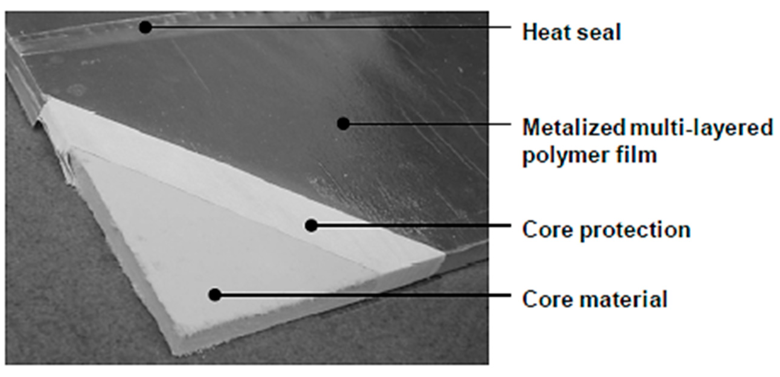
25], depending on their thermal conductivities. Generally, in terms of space, reduced thickness of the wall is always preferred by builders and property owners. In such cases, Vacuum Insulation Panels (VIP) are ideal thermal insulation solutions with enhanced performance in reduced thickness. VIP exhibits a five-fold greater thermal resistance than, for example, mineral wool, allowing for a significant increase in energy efficiency. Therefore, the thickness required to achieve the same thermal performance is much less in VIP than in traditional insulation materials. In the meantime, VIP also helps to preserve the aesthetics and features of the building.
Figure 4 illustrates an image of a VIP wrapped in a heat-sealed metalised multi-layered polymer film.
Peng and Yang (2016) investigated the effect of VIP over the XPS insulation and concluded that replacing the same thickness of VIP from XPS could increase the indoor net residential area by 2% and reduce the annual electricity consumption by 20% [
28].
Table 1 lists the thermal insulation materials on the market and their advantages and disadvantages compared to VIP insulation material. The comparison is made in terms of physical properties, economy, thermal performance, durability, and environmental impact.
Table 1 reflects the lower thermal conductivity of the VIP, and it is interesting to investigate the VIP panels’ effects in improving the thermal performance of LSF walls, which this study addressed.
A study focused on the economic consequences of VIP use in Swedish multi-family buildings was performed by Pramsten and Hedlund [
29]. A wall with VIP was compared to a wall with the same thermal transmittance using EPS. With the assumptions in the study, VIP is not an economical alternative compared to EPS. The VIP price has to decrease, or the energy price has to increase to make VIP an economical alternative for buildings [
25,
29]. Grynning et al. [
30] presented a simplified economical calculation with a 6 cm thick VIP employed in an exterior wall. At a market value of approx. EUR 2300 per square meter, there were no additional costs encountered in the construction of wall panels using VIP compared to mineral wool. According to his study, the thermal resistance of VIP alone was 5 times higher than that of mineral wool, and the cost of the 6 cm thick VIP was approx. EUR 200 per square meter [
25], while the cost of mineral wool (150 mm) is approx. EUR 16 per square meter [
30]. Here, even though cost wise mineral wool appears to be the best option, due to the limitation in LSF wall thicknesses, VIP’s stands out as more beneficial.
The payback period of using VIP in four different retrofitting scenarios was calculated by Alam et al. (2011), where the thickness of the VIP was varied (presented in
Table 2). In the study, the payback period of using VIP was compared to walls with the same thermal resistance using EPS [
31]. According to
Table 2, the payback period of VIP is higher than the EPS; however, the same U-value could be achieved with 5 times less thickness of VIP. It could be summarised that the VIP is an expensive insulation material having favourable characteristics in thermal performance. Therefore, a proper investigation of the influence of VIP panels on the hybrid frame LSF wall systems was studied and presented in this study using numerical analysis.
5. Development and Verification of the FE Model
U-value is the thermal transmittance of the wall configuration. It directly relates to the element’s thermal performance; if the U-value is low, it implies that the wall’s thermal performance is better. The U-value (
) has an inverse relationship with thermal resistance (
) of the element (Equation (1)). The thermal resistance of the element depends on the internal surface thermal resistance (
), external surface thermal resistance (
), and the element layer resistance (
) (Equation (2)). Further, heat flux (ϕ) and the temperature difference (ΔT) between the external and internal surfaces has a relationship with the U-value (Equation (3)). Thermal resistance has a co-relationship with the thermal conductivity
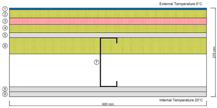
and the layer’s thickness (d) as expressed in Equation (4). If a wall configuration is available with different layers of materials, using Equations (1) and (2), the U-value of the wall configuration could be easily determined. However, instead of layers, if the combination of materials is in complex geometry, such as LSF wall systems with studs, the direct equation could not be used; instead, complex equations and techniques are required. Therefore, in this study, a simple FE model along with Equations (3) and (4) were utilised to determine the U-value of the LSF wall configuration.
Two-dimensional (2D) and three-dimensional (3D) heat transfer analyses were conducted in 3D FEM software, ABAQUS/CAE [
32], to determine the LSF wall configurations’ thermal transmittance, and it was observed that both 2D and 3D results were identical. Steady-state heat transfer depends on the thermal conductivity of the material. Wall configurations considered in this study consist of gypsum plasterboards, OSB, steel studs and filling materials. Each material’s thermal conductivity and orientation has an influence on the wall panel’s U-value. Thermal conductivity values of the materials used in the study are tabulated in
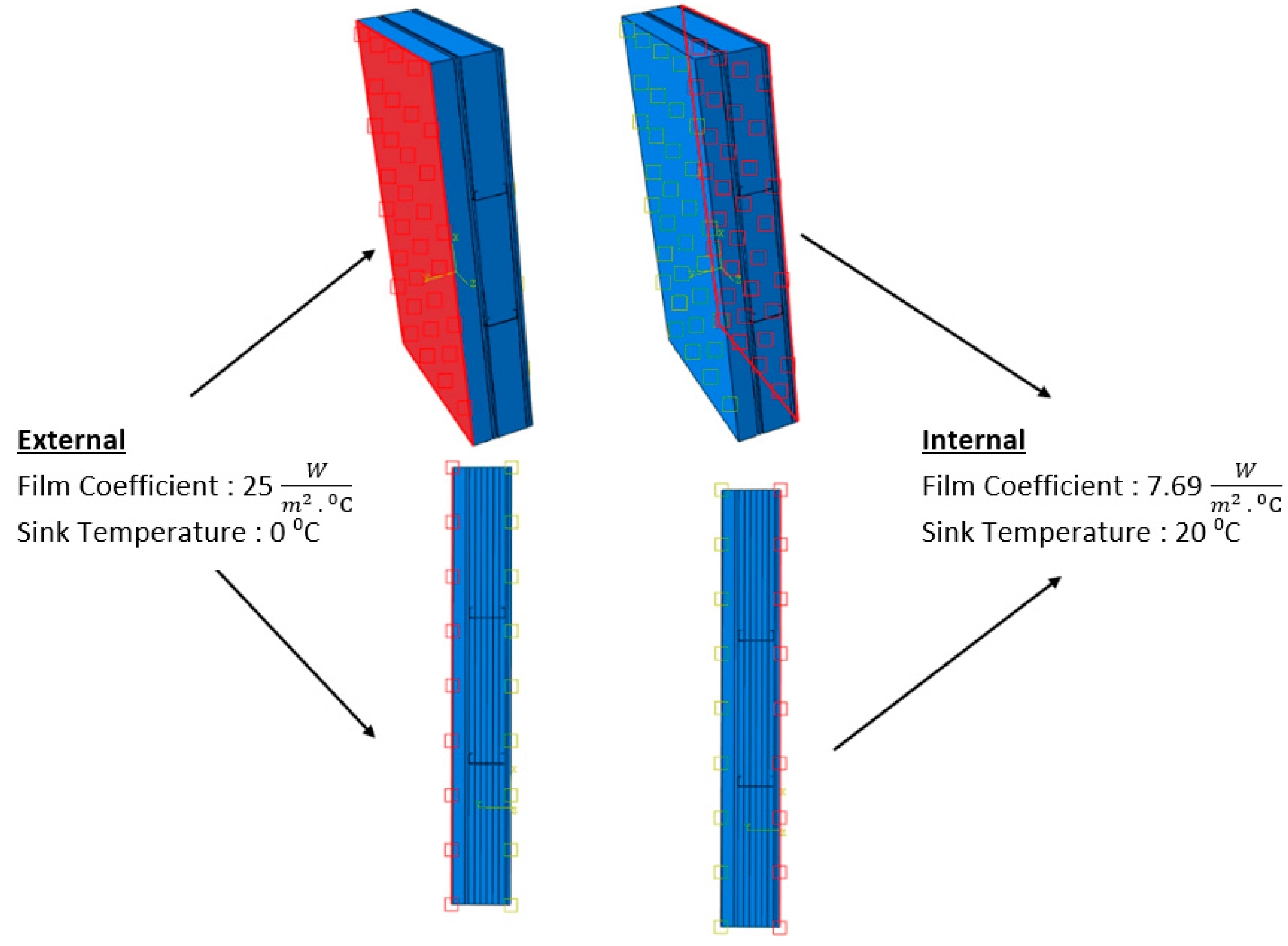
Table 3. External and Internal temperature boundary conditions were set for 0 °C and 20 °C, respectively. The convective surface heat transfer coefficients were set according to BS EN ISO 6946 [
33]. Two surface film condition interactions were defined separately in the external and internal surfaces to achieve these boundary conditions in the developed FE model. For the external surface, film coefficient of 25 W/m
2 K was set with a sink temperature of 0 °C, whereas for the internal surface, film coefficient of 7.69 W/m
2 K was set with a sink temperature of 20 °C [
21,
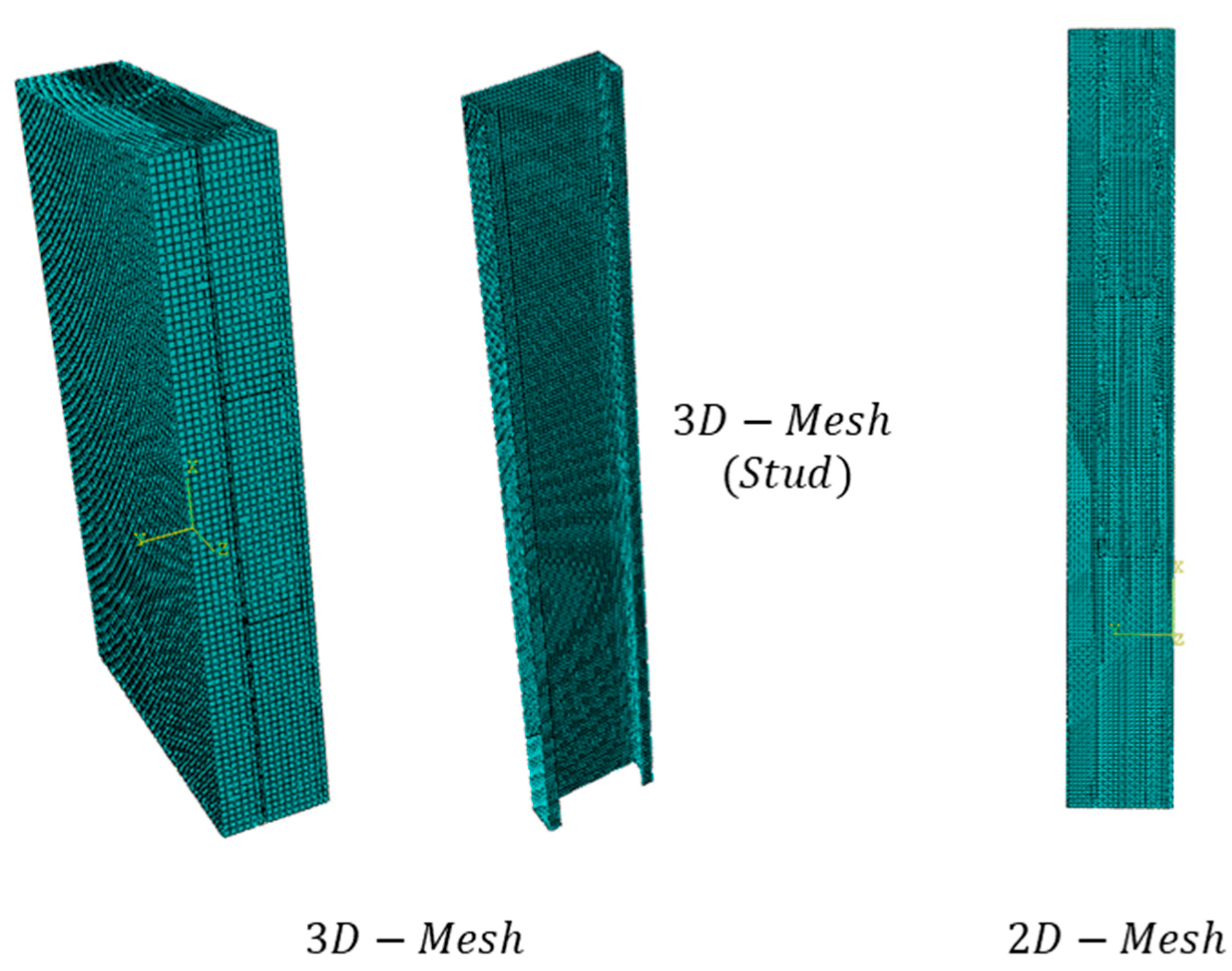
33]. Heat transfer elements (DC3D8 elements) were used to develop the model. DC3D8 is an 8 node linear isoparametric element used in Abaqus CAE to solve 3D heat transfer problems. Global seeding of 20 mm was used in the 3D analysis for all the elements except studs, where 2 mm mesh size was used. In 2D analysis, 10 mm mesh size was used for the entire wall panel. Steady-state heat transfer analysis was conducted to obtain the heat flux results.
Based on Equation (3), U-value was calculated, dividing the average heat flux from the temperature difference (20 °C). The cavity of the configurations was modelled as air layers. All the cavities considered in this study were considered closed cavities. Air gap thermal resistance was considered a constant value of 0.18 m
2·K/W as per [
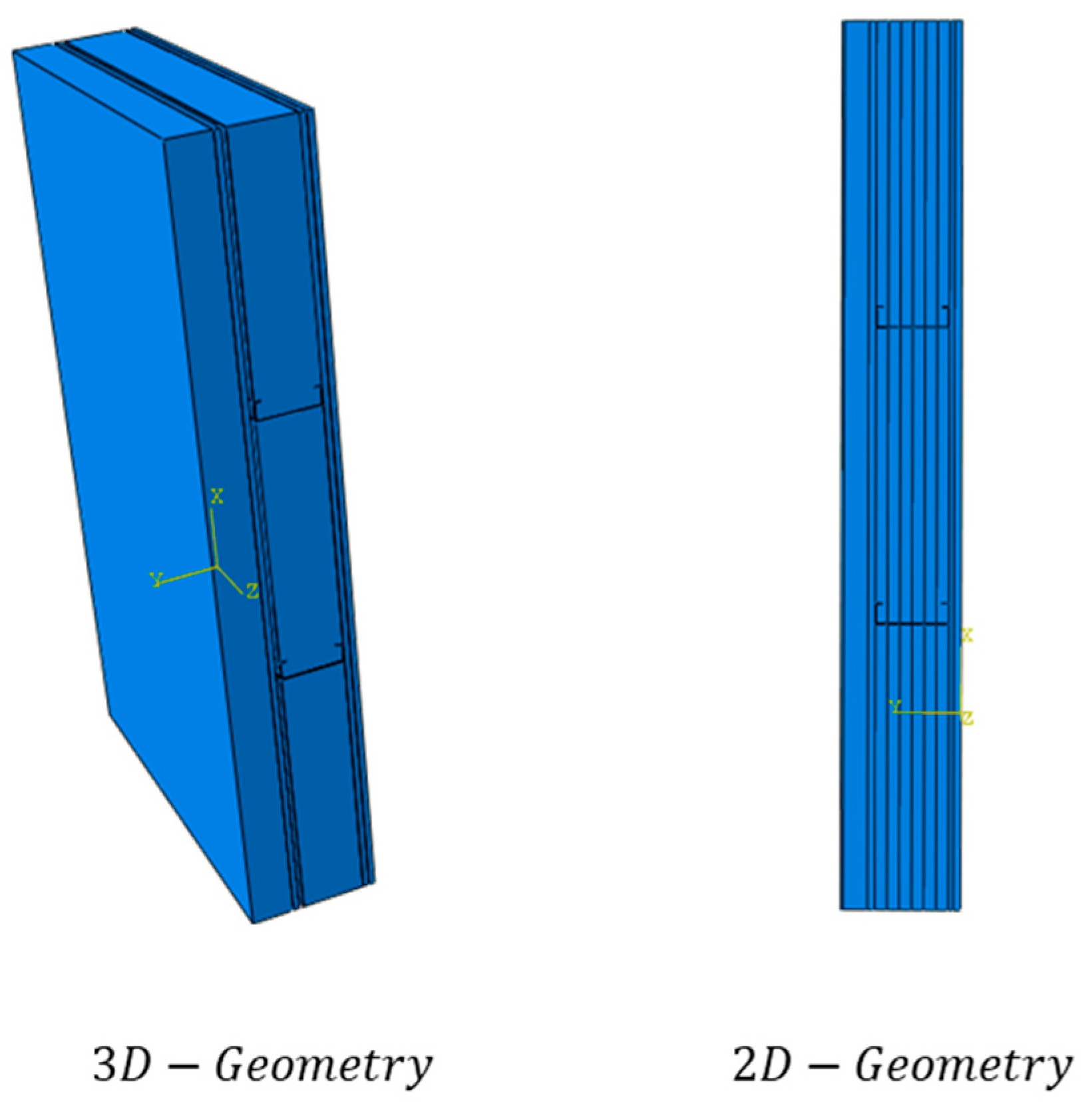
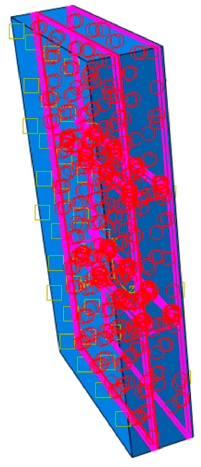
34], and in the developed FE model, the air layer was simulated through an equivalent thermal conductivity value based on the relationship given in Equation (4). Here the heat transfer through the air gap was calculated based on the thickness of the air layer. Therefore, cavity layer thermal conductivity increases with the thickness, which ultimately affects the thermal performance of the wall panel. The geometry modelling, applying boundary conditions, applying tie constraints, and meshing are shown in
Figure 5,
Figure 6,
Figure 7 and
Figure 8.
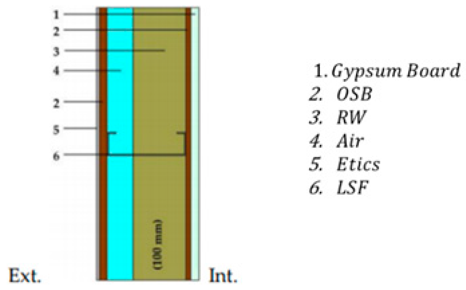
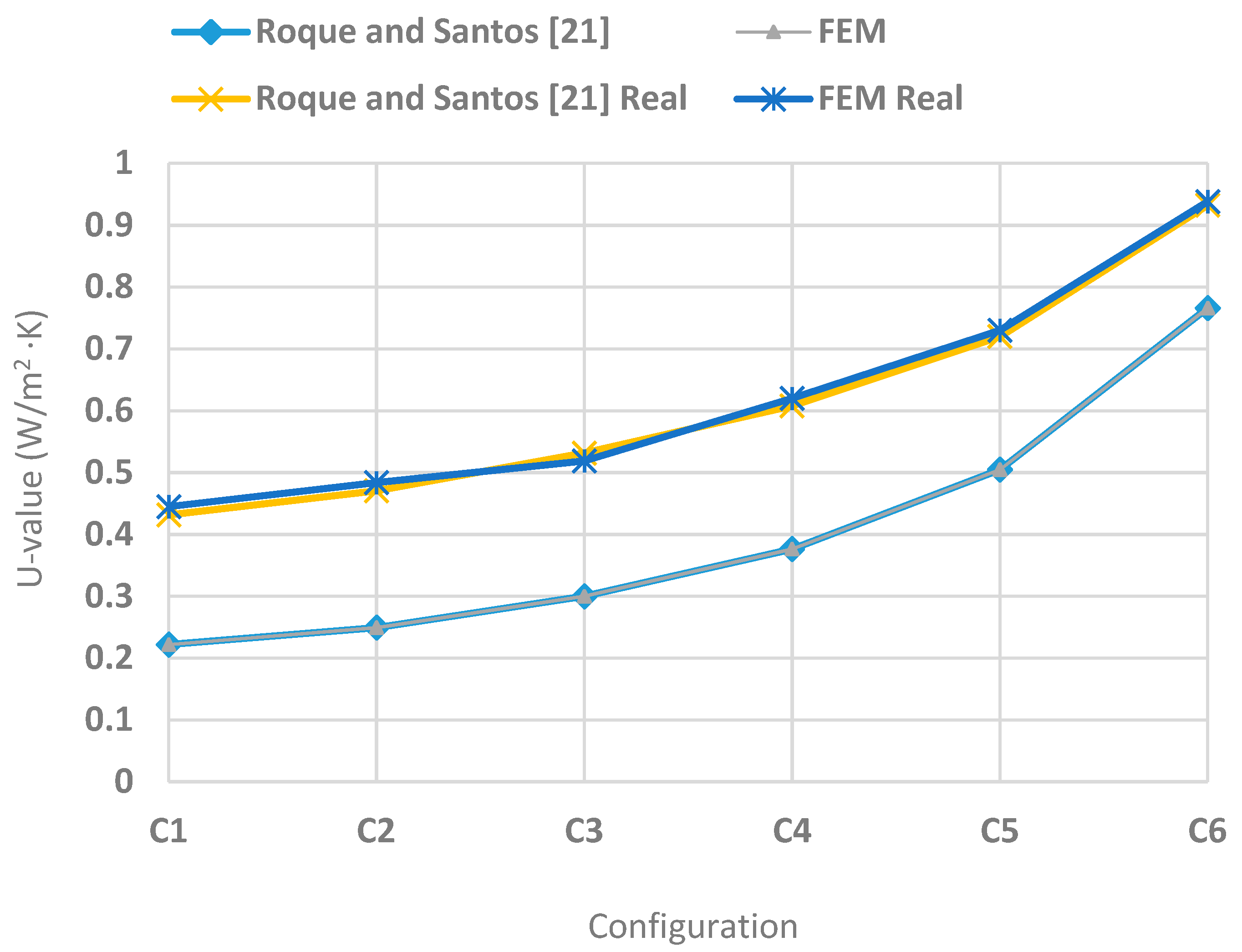
In their study on the effectiveness of thermal insulation in lightweight steel-framed walls with respect to its position, Roque and Santos [
21] have reported the U-values of LSF walls with and without steel studs.
Figure 9 shows the configuration considered by Roque and Santos [
21]. The same parameters and material properties were incorporated, and U-value results were compared to verify the developed FE model in ABAQUS. Twelve models, as tabulated in
Table 4, were compared with the developed ABAQUS FE model results. The comparison of the U-value results of the developed FE model with the previous literature results is shown in
Table 5 and compared in
Figure 10. It can be seen that the Developed FE model results match the previous literature results, which implies that the developed model could be utilised to determine the U-value of different LSF configurations.
6. Parametric Study
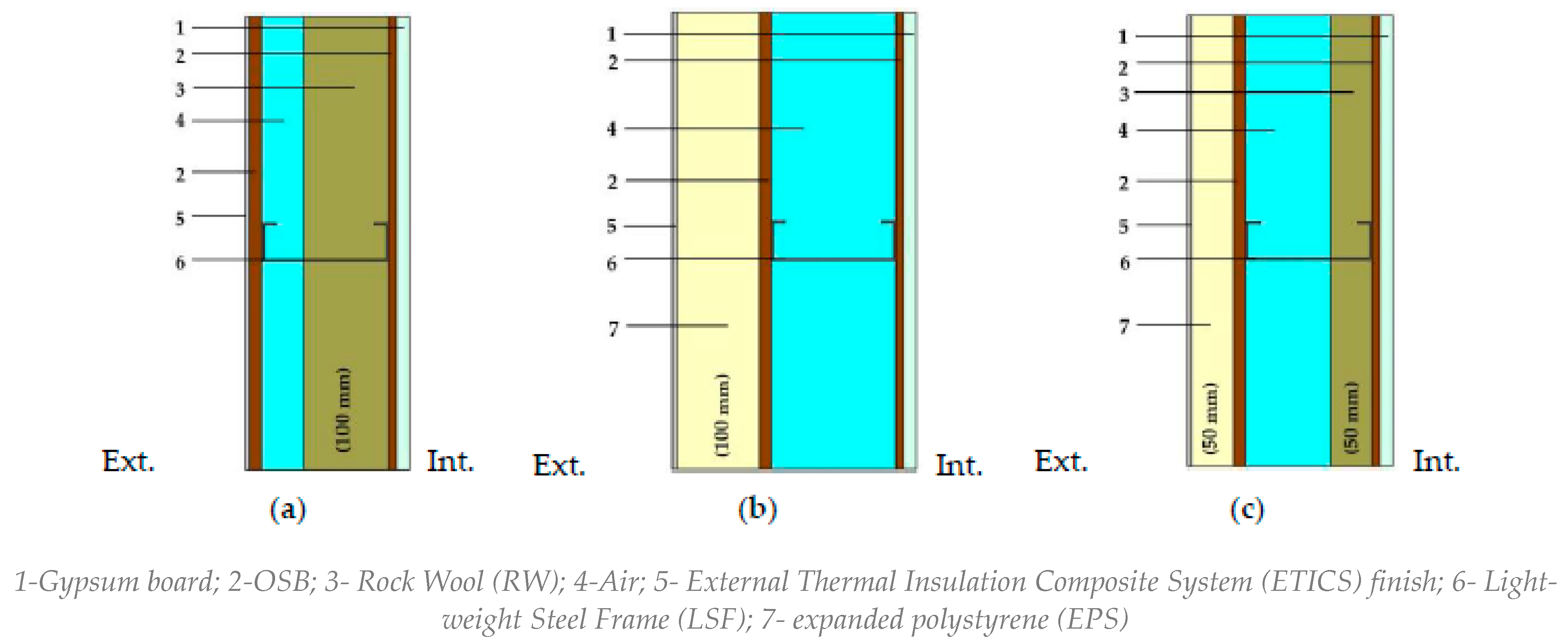
The verified FE model was utilised to determine the effect of novel thermal insulation Vacuum Insulation Panels (VIP), their position, and the effect of OSB and plasterboard on the thermal transmittance of LSF walls. A total of 56 model configurations were considered, as summarised in
Table 6. Each model’s U-value was analysed with stud and without stud to visualise the thermal bridging effect of steel studs in the LSF wall systems.
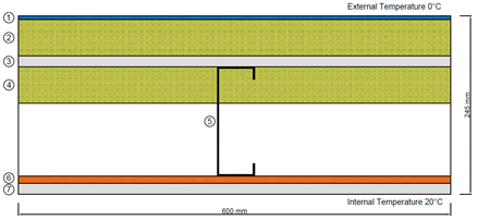
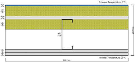
Model 01, as illustrated in
Table 6, consists of 15 mm plasterboard, 10 mm OSB panel, 150 mm
43 mm
15 mm steel studs of 2 mm thickness in 600 mm spacing, a rockwool insulation layer varying from 0 to 150 mm, 15 mm plasterboard, 50 mm rockwool, and 5 mm Etics finish. OSB panel (10 mm) of the Model 01 was replaced with the 15 mm plasterboard in Model 02 to determine the effect of plasterboard and OSB in the thermal performance of LSF. OSB panels are considered to be crucial in load-bearing and stability walls because they provide additional resistance to horizontal lateral loads; hence it is important to examine the effect of OSB replacing the plasterboard in LSF wall systems [
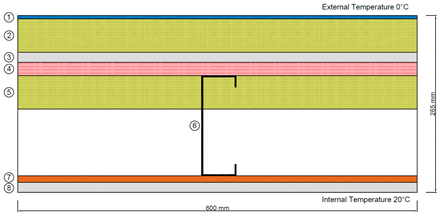
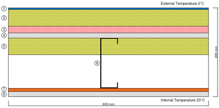
35]. Model 03 and Model 04 configurations are similar to Model 01 and Model 02, respectively; however, 20 mm of VIP was introduced to the wall panel just after the steel stud on the external side to investigate the effect of the VIP panel on the thermal performance of the LSF wall system. To determine the effect of the location of the VIP on the thermal performance of LSF, Model 05 and 06 VIP panel was placed after the external side plasterboard, and Model 07 and 08 VIP panel was placed at the middle of the external rockwool layer.
7. Results and Discussion
7.1. Results Overview
Obtained U-value results of 112 models as described in
Section 6 are tabulated in
Table 7. Although EN ISO 6946 [
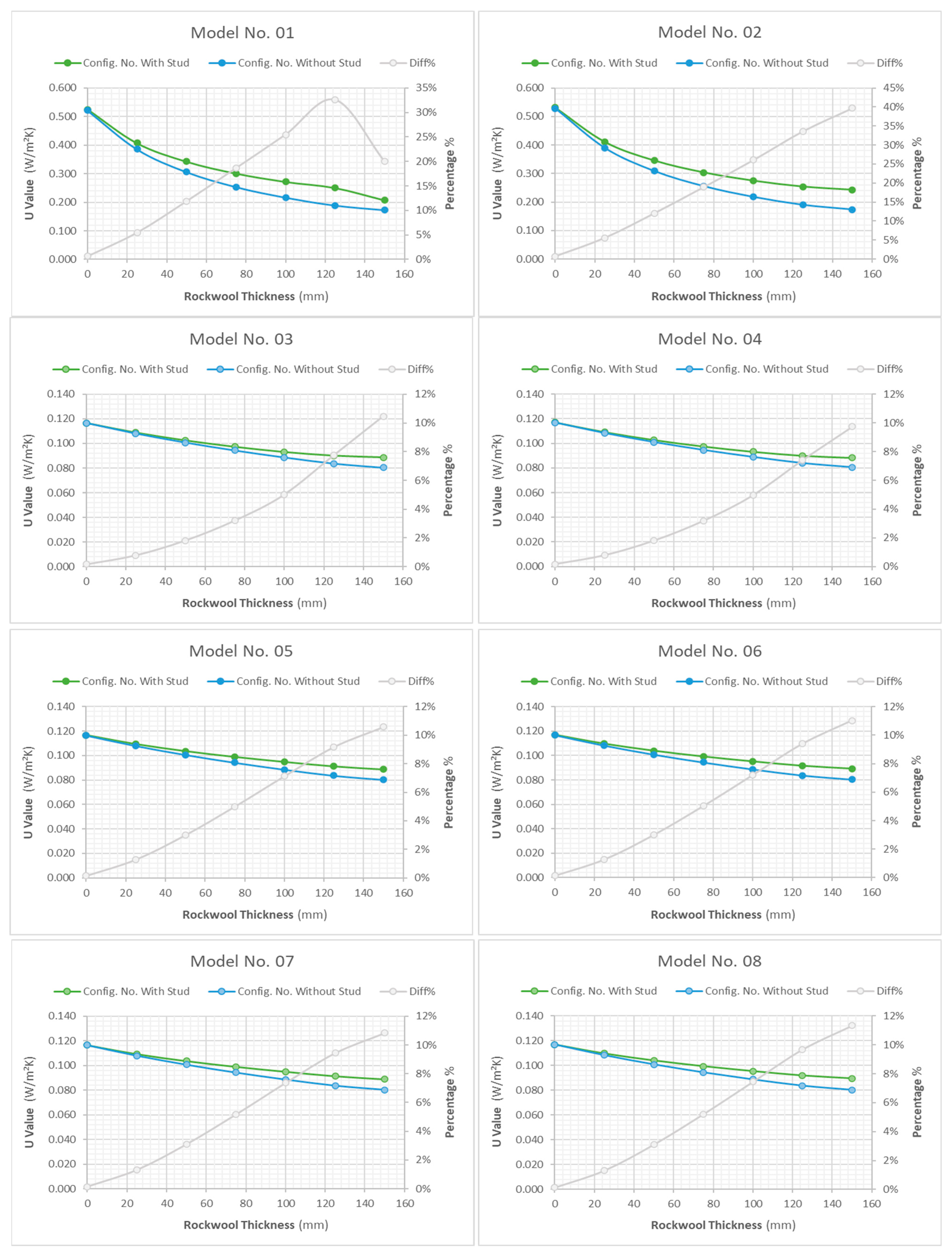
34] specifies that the final results of thermal resistance values should be rounded to two decimal places, the U-values are reported with three decimal places to enhance the precision of comparative analysis even when similar values are acquired. U-value variation of each configuration with the internal insulation layer thickness is graphically represented in
Figure 11. It can be observed that the U-value is reducing with the internal insulation thickness. Since insulation material rockwool has a lower thermal conductivity, the insulation layer increment reduces the LSF wall’s thermal transmittance. Further, results exhibit that the effect of internal insulation thickness is higher in Model 01 and Model 02, where no VIP was used. Model 01 reduction percentage of U-value is 60% from 0 mm internal insulation to 150 mm insulation, whereas in Model 03, the reduction is only 23%. This result was observed due to the lower thermal conductivity of VIP. Since the thermal conductivity of VIP is less than 10 times that of rockwool approximately, according to Equation (4) it can be argued that the effect of 20 mm VIP is equal to 200 mm (10 times 20) of rockwool. VIP has dominated the U-value of the LSF wall system over the rockwool, which makes the effect of the internal insulation thickness insignificant.
Moreover, it can be seen U-value is reduced when the steel stud is removed from the LSF wall system, which implies an improvement in the thermal performance. It can be observed that the reduction percentage of the U-value without the stud is increasing with the internal insulation thickness of the LSF wall system for all the configurations considered. However, in real LSF, wall systems can not be manufactured without steel studs since steel studs are the load-bearing element of the LSF wall system.
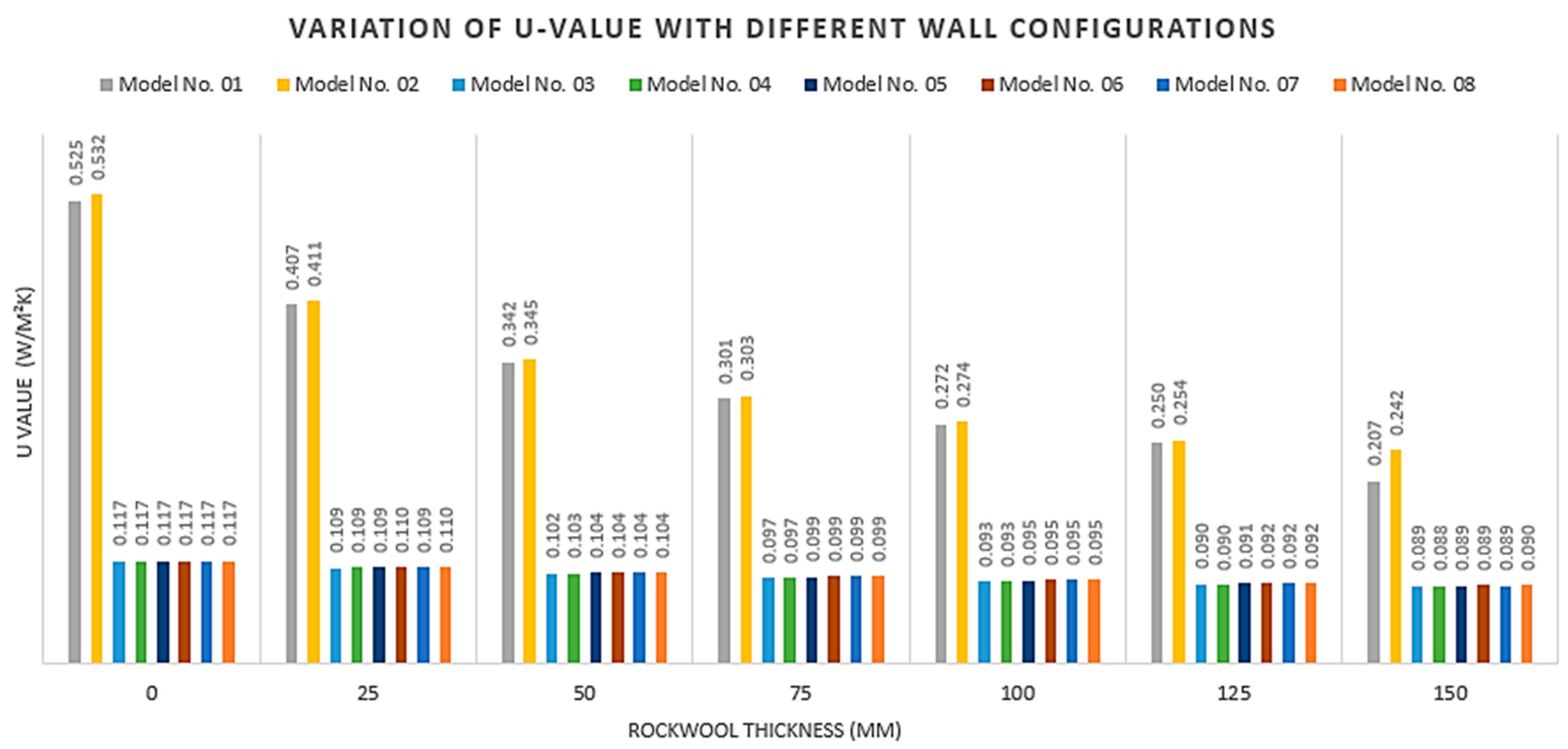
Variation of U-value with different wall configurations is shown in
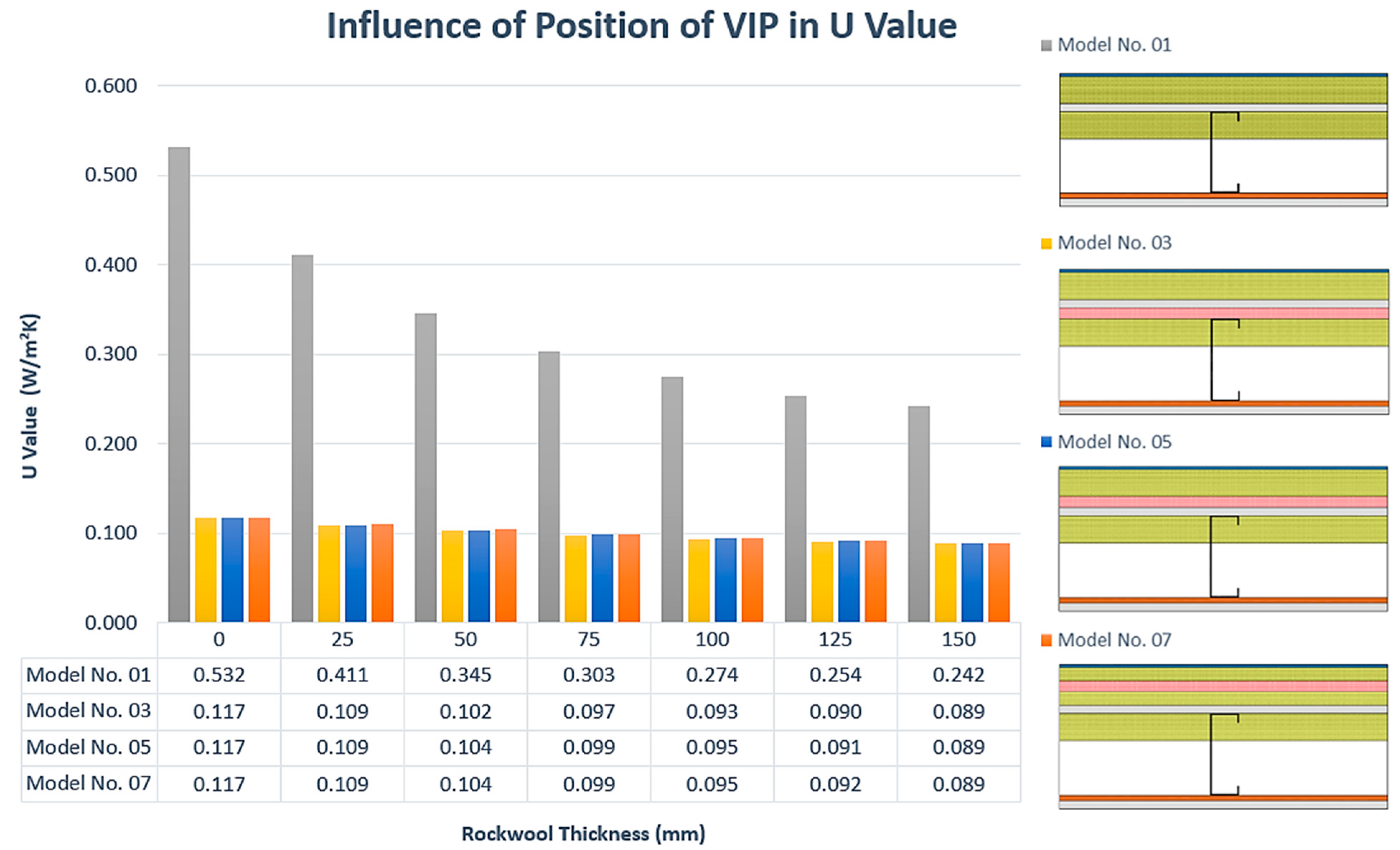
Figure 12. Model 03–08 have exhibited lower U-value compared to Model 01 and 02 due to the introduction of the VIP panel. Comparing the U-values of Model 01 and 02, it can be seen that Model 01 has a lower U-value. This was resulted due to the lower thermal conductivity of OSB. Considerable reduction of U-value is observed with the introduction of the 20 mm VIP to the LSF wall system, which implies an improvement in thermal performance. The reduction percentage of U-value with the introduction of VIP compared to Model 02 is 78%, 73%, 69%, 67%, 65%, 64%, and 63% for 0 mm, 25 mm, 50 mm, 75 mm, 100 mm, 125 mm, and 150 mm internal insulation thickness, respectively. Therefore, the reduction percentage of U-value is lowering with the increment of the internal insulation thickness. U-value variations of Model 03, 05, and 07 are graphically presented in
Figure 13 to highlight the effect of the VIP position on the U-value of the LSF wall.
Figure 13 clearly implies that the VIP positions considered in this study do not notably affect the overall LSF wall U-value.
7.2. Thermal Regulation Requirement
Building Regulations UK (England) Part L [
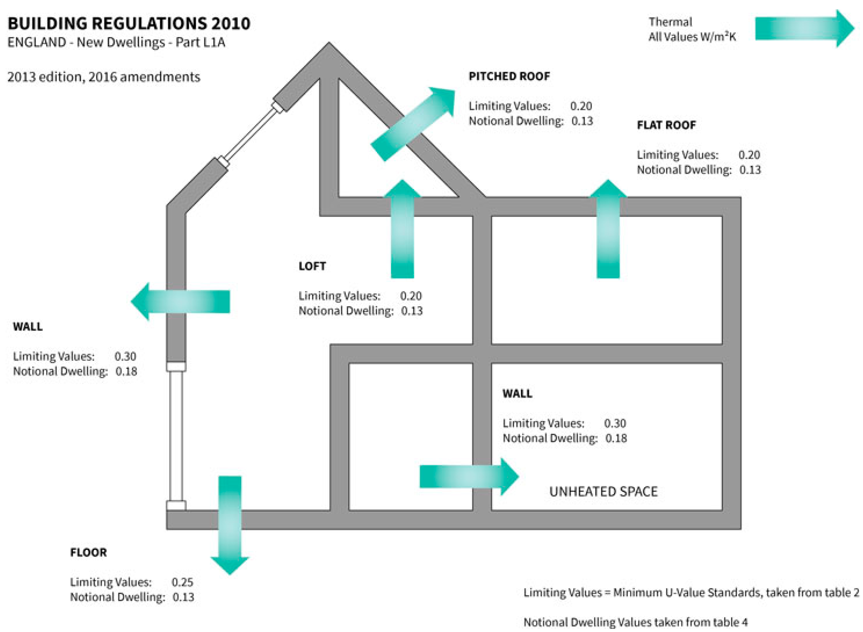
36] expresses clear guidelines for making a new property more energy efficient by stipulating benchmark values for building elements. According to the UK (England) Building Regulations for wall, floor and roof elements, the U-value requirements set out for new dwelling units are illustrated in
Figure 14. In addition, obtained thermal transmittance values (real scenario, with studs) are compared with the requirements provided by the UK (England) thermal regulation for new dwelling units [
36] to determine the adequacy of the proposed walling units with optimum configuration.
According to
Figure 14, the limiting U-Value for both internal and external walls is 0.3 W/m
2 K, and for notional dwelling, U-value is 0.18 /m
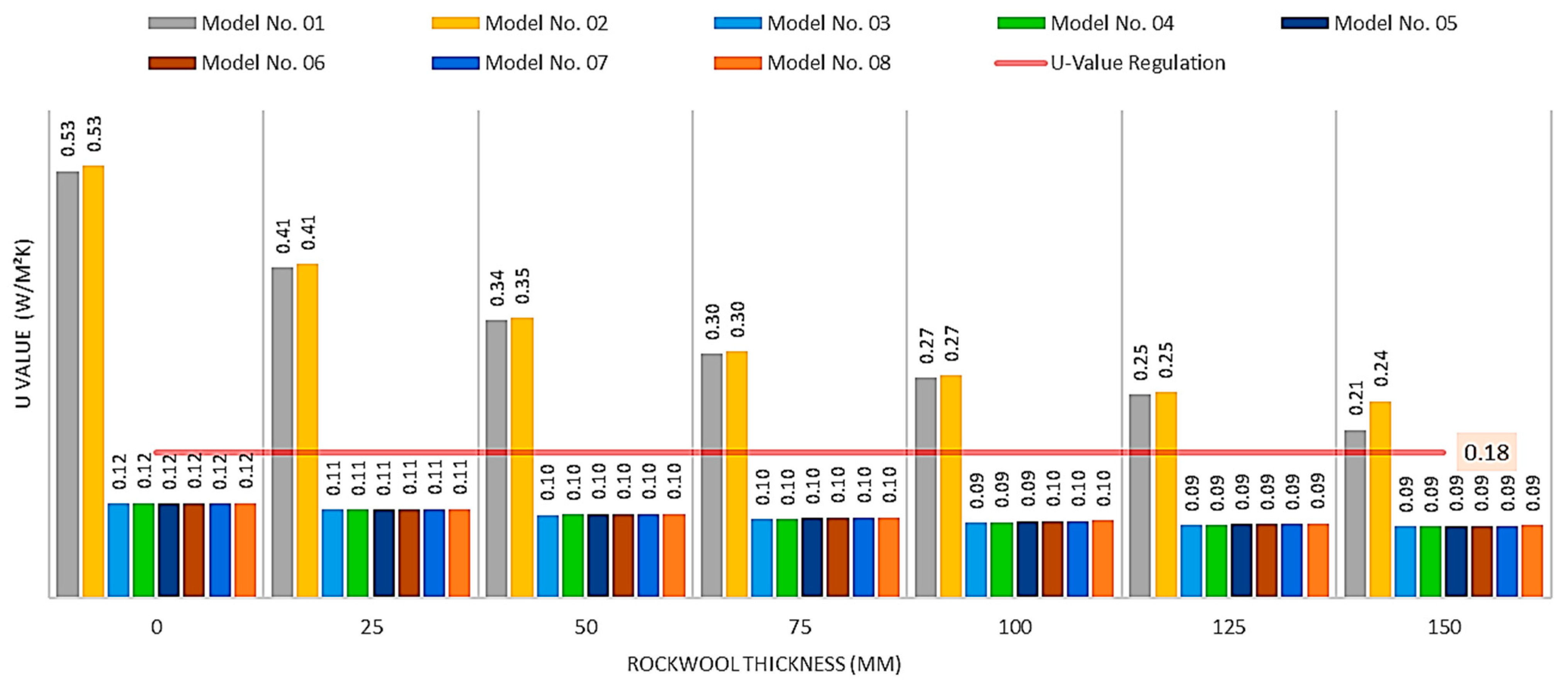
2 K. Adequacy of the LSF wall configurations studied in this study based on the UK building regulation is shown in
Figure 15. It can be seen that none of the walling units without VIP panels were in accordance with the notional dwelling unit requirement. However, all the configurations with 20 mm VIP could be employed as walling units adequating to the UK building regulations. Furthermore, considering the limiting U-value of 0.3 W/m
2 K LSF configurations without VIP panels could also be employed if at least 75 mm of internal rockwool insulation is applied.
8. Conclusions
The thermal performance of LSF wall configurations based on the U-value of the wall system was investigated using numerical analysis. A total of 112 numerical models were analysed to examine the U-value variation of LSF wall configuration with the introduction of novel insulation material Vacuum Insulation Panels(VIP), the effect of the position of the VIP, the effect of the replacing of OSB with plasterboard, and the effect of internal insulation thickness. LSF wall configuration with plasterboard and rockwool insulation (Model 02) has shown the highest U-value, the least favourable thermal performance wall configuration. When external 15 mm plasterboard is replaced with 10 mm OSB (Model 01), U-value has reduced from 0.5% to 1% when internal rockwool insulation thickness is reduced from 150 mm to 0 mm. Therefore, replacing OSB panels from plasterboard could be identified as an advantage for LSF walls in thermal performance. It was observed that the introduction of a 20 mm VIP panel had reduced the U-value of the LSF walls by a considerable percentage, which implies the thermal performance is improved. The reduction percentage of U-value with the introduction of VIP compared to Model 02 is 78%, 73%, 69%, 67%, 65%, 64%, and 63% for 0 mm, 25 mm, 50 mm, 75 mm, 100 mm, 125 mm, and 150 mm internal insulation thickness, respectively. However, comparing the U-value results of Models 03, 05, 07, and Models 04, 06, 08, the VIP panel position in the LSF wall configurations considered in this study exhibited no effect. VIP panels thermal conductivity is approximately 10 times lower than the thermal conductivity of rockwool insulation; therefore, according to Equation (4), it can be argued that the effect of 20 mm VIP layer (which was considered in this study) is approximately equal to 200 mm (10 times 20 mm) of rockwool layer. The above explanation is proved by the U-value results showing that better thermal performance (lower U-value) in LSF wall configuration with 20 mm VIP and 0 mm rockwool than the LSF wall configuration with 150 mm rockwool and 0 mm VIP. Therefore VIP could be identified as an ideal solution in a variety of regions of the building envelope where strong thermal resistance is required with constrained wall thicknesses. U-value results of the LSF wall configurations were compared with the UK building regulation requirements for U-value in walls. It can be concluded that all the configurations with VIP panels are acceptable with the notional dwelling U-value specified in the UK building regulations. None of the LSF wall configurations without VIP was acceptable for the above criterion. However, considering the limiting U-value specified in the UK building regulations, LSF configurations without VIP panels could also be employed if at least 75 mm of internal rockwool insulation is applied. Therefore, this study could be utilised in a selection of LSF walling units for a particular application based on its thermal performance, UK building requirement, and wall thickness constraints. Compared to traditional insulating materials, vacuum insulation panels can enhance both the thermal resistance and the building envelope’s energy efficiency. To hasten the broader adoption of VIPs in constructions, more similar and extensive research studies and increased promotion validating its benefits over conventional insulation materials are recommended.
Author Contributions
Conceptualization, H.R.; Data curation, H.R. and I.U.; Formal analysis, I.U.; Methodology, H.R., I.U. and P.G.; Project administration, K.P.; Supervision, K.P., P.S., C.K. and B.N.; Validation, P.G.; Writing—original draft, H.R.; Writing—review & editing, K.P., P.S., C.K., B.N. and D.P. All authors have read and agreed to the published version of the manuscript.
Funding
This research was funded by Innovate UK (Partnership number: 12060), ESS Modular Limited and Northumbria University And The APC was funded by Northumbria University.
Institutional Review Board Statement
Not applicable.
Informed Consent Statement
Not applicable.
Data Availability Statement
Not applicable.
Conflicts of Interest
The authors declare no conflict of interest.
References
- Dodangoda, M.T.; Mahendran, M.; Keerthan, P.; Frost, R.L. Developing a performance factor for fire rated boards used in LSF wall systems. Fire Saf. J. 2019, 109, 102872. [Google Scholar] [CrossRef]
- Alfawakhiri, F.; Sultan, M. Fire Resistance of Loadbearing Lsf Assemblies. 01/01 2000. Available online: https://scholarsmine.mst.edu/cgi/viewcontent.cgi?article=1503&context=isccss (accessed on 14 April 2021).
- Baleshan, B.; Mahendran, M. Fire design rules to predict the moment capacities of thin-walled floor joists subject to non-uniform temperature distributions. Thin-Walled Struct. 2016, 105, 29–43. [Google Scholar] [CrossRef]
- Dias, Y.; Keerthan, P.; Mahendran, M. Fire performance of steel and plasterboard sheathed non-load bearing LSF walls. Fire Saf. J. 2019, 103, 1–18. [Google Scholar] [CrossRef]
- Gnanachelvam, S.; Ariyanayagam, A.; Mahendran, M. Fire resistance of light gauge steel framed wall systems lined with PCM-plasterboards. Fire Saf. J. 2019, 108, 102838. [Google Scholar] [CrossRef]
- Rusthi, M.; Keerthan, P.; Mahendran, M.; Ariyanayagam, A. Investigating the fire performance of LSF wall systems using finite element analyses. J. Struct. Fire Eng. 2017, 8, 354–376. [Google Scholar] [CrossRef] [Green Version]
- Santos, P.; Mateus, D. Experimental assessment of thermal break strips performance in load-bearing and non-load-bearing LSF walls. J. Build. Eng. 2020, 32, 101693. [Google Scholar] [CrossRef]
- Soares, N.; Santos, P.; Gervásio, H.; Costa, J.; da Silva, L.S. Energy efficiency and thermal performance of lightweight steel-framed (LSF) construction: A review. Renew. Sustain. Energy Rev. 2017, 78, 194–209. [Google Scholar] [CrossRef]
- Lawson, R.M. Energy Efficient Housing using Light Steel Framing; The Steel Construction Institute: Ascot, UK, 2007. [Google Scholar]
- Santos, P.; Gonçalves, M.; Martins, C.; Soares, N.; Costa, J.J. Thermal transmittance of lightweight steel framed walls: Experimental versus numerical and analytical approaches. J. Build. Eng. 2019, 25, 100776. [Google Scholar] [CrossRef]
- Directive 2010/31/EU on the Energy Performance of Buildings (Recast)—19 May 2010; European Parliament, Council of the European Union: Brussels, Belgium, 2010.
- Chen, F.; Wittkopf, S. Summer condition thermal transmittance measurement of fenestration systems using calorimetric hot box. Energy Build. 2012, 53, 47–56. [Google Scholar] [CrossRef]
- Santos, P.; Silva, L.; Ungureanu, V. Energy Efficiency of Lightweight Steel-Framed Buildings. 2012. Available online: https://www.intechopen.com/chapters/53060 (accessed on 12 April 2021).
- Ferreira, M.; Almeida, M.; Rodrigues, A. Cost-optimal energy efficiency levels are the first step in achieving cost effective renovation in residential buildings with a nearly-zero energy target. Energy Build. 2016, 133, 724–737. [Google Scholar] [CrossRef]
- Ahmadi, M.M.; Keyhani, A.; Kalogirou, S.A.; Lam, S.S.; Peng, W.; Tabatabaei, M.; Aghbashlo, M. Net-zero exergoeconomic and exergoenvironmental building as new concepts for developing sustainable built environments. Energy Convers. Manag. 2021, 244, 114418. [Google Scholar] [CrossRef]
- Janjua, S.Y.; Sarker, P.K.; Biswas, W.K. Sustainability implications of service life on residential buildings—An application of life cycle sustainability assessment framework. Environ. Sustain. Indic. 2021, 10, 100109. [Google Scholar] [CrossRef]
- Payyanapotta, A.; Thomas, A. An analytical hierarchy based optimization framework to aid sustainable assessment of buildings. J. Build. Eng. 2021, 35, 102003. [Google Scholar] [CrossRef]
- Rodrigues, E.; Soares, N.; Fernandes, M.S.; Gaspar, A.R.; Gomes, Álvaro; Costa, J.J. An integrated energy performance-driven generative design methodology to foster modular lightweight steel framed dwellings in hot climates. Energy Sustain. Dev. 2018, 44, 21–36. [Google Scholar] [CrossRef] [Green Version]
- Sharma, A.; Saxena, A.; Sethi, M.; Shree, V. Varun Life cycle assessment of buildings: A review. Renew. Sustain. Energy Rev. 2011, 15, 871–875. [Google Scholar] [CrossRef]
- Directive (EU) 2018/844 Amending Directive 2010/31/EU on the Energy Performance of Buildings and Directive 2012/27/EU on Energy Efficiency; European Parliament, Council of the European Union: Brussels, Belgium, 2018.
- Roque, E.; Santos, P. The Effectiveness of Thermal Insulation in Lightweight Steel-Framed Walls with Respect to Its Position. Buildings 2017, 7, 13. [Google Scholar] [CrossRef] [Green Version]
- Zhan, Q.; Xiao, Y.; Musso, F.; Zhang, L. Assessing the hygrothermal performance of typical lightweight steel-framed wall assemblies in hot-humid climate regions by monitoring and numerical analysis. Build. Environ. 2021, 188, 107512. [Google Scholar] [CrossRef]
- Degtyareva, N.; Gatheeshgar, P.; Poologanathan, K.; Gunalan, S.; Lawson, M.; Sunday, P. Combined bending and shear behaviour of slotted perforated steel channels: Numerical studies. J. Constr. Steel Res. 2019, 161, 369–384. [Google Scholar] [CrossRef]
- Way, A.G.J.; Kendrick, C. Avoidance of Thermal Bridging in Steel Construction; The Steel Construction Institute: Ascot, UK, 2008. [Google Scholar]
- Johansson, P. Vacuum Insulation Panels in Buildings: Literature Review. 2012. Available online: https://research.chalmers.se/en/publication/155961 (accessed on 10 April 2021).
- Kesawan, S.; Mahendran, M. Fire tests of load-bearing LSF walls made of hollow flange channel sections. J. Constr. Steel Res. 2015, 115, 191–205. [Google Scholar] [CrossRef]
- Martins, C.; Santos, P.; Simoesdasilva, L. Lightweight steel-framed thermal bridges mitigation strategies: A parametric study. J. Build. Phys. 2016, 39, 342–372. [Google Scholar] [CrossRef]
- Peng, C.; Yang, J. Structure, Mechanism, and Application of Vacuum Insulation Panels in Chinese Buildings. Adv. Mater. Sci. Eng. 2016, 2016, 1358072. [Google Scholar] [CrossRef] [Green Version]
- Pramsten, E.; Hedlund, M. Ekonomisk Analys av Vakuumisoleringspaneler i Ytterväggar. 2009. Available online: http://www.diva-portal.org/smash/record.jsf?pid=diva2%3A423887&dswid=1813 (accessed on 12 March 2021).
- Baetens, R.; Jelle, B.P.; Thue, J.V.; Tenpierik, M.; Grynning, S.; Uvsløkk, S.; Gustavsen, A. Vacuum insulation panels for building applications: A review and beyond. Energy Build. 2010, 42, 147–172. [Google Scholar] [CrossRef] [Green Version]
- Alam, M.; Singh, H.; Limbachiya, M. Vacuum Insulation Panels (VIPs) for building construction industry—A review of the contemporary developments and future directions. Appl. Energy 2011, 88, 3592–3602. [Google Scholar] [CrossRef] [Green Version]
- ABAQUS. ABAQUS/CAE Software Version 3.14-1. 2016. Available online: https://www.3ds.com/productsservices/simulia/products/abaqus/abaquscae (accessed on 29 November 2020).
- Alkhalidi, A.; Hatuqay, D. Energy efficient 3D printed buildings: Material and Techniques selection worldwide study. J. Build. Eng. 2020, 30, 101286. [Google Scholar] [CrossRef]
- BS EN ISO 6946:2017: Building Components and Building Elements. Thermal Resistance and Thermal Transmittance. Calculation Methods; British Standards Institute: London, UK, 2017.
- Perera, D.; Poologanathan, K.; Gillie, M.; Gatheeshgar, P.; Sherlock, P.; Nanayakkara, S.; Konthesingha, K. Fire performance of cold, warm and hybrid LSF wall panels using numerical studies. Thin-Walled Struct. 2020, 157, 107109. [Google Scholar] [CrossRef]
- The Building Regulations 2010—L1A Conservation of Fuel and Power in New Buildings. 2010. Available online: https://assets.publishing.service.gov.uk/government/uploads/system/uploads/attachment_data/file/540326/BR_PDF_AD__L1A__2013_with_2016_amendments.pdf (accessed on 10 May 2021).
- Understanding Building Regulations Relating to Insulation [Online]. Available online: https://ybsinsulation.com/understanding-building-regulations-insulation/ (accessed on 30 March 2021).
| Publisher’s Note: MDPI stays neutral with regard to jurisdictional claims in published maps and institutional affiliations. |
© 2021 by the authors. Licensee MDPI, Basel, Switzerland. This article is an open access article distributed under the terms and conditions of the Creative Commons Attribution (CC BY) license (https://creativecommons.org/licenses/by/4.0/).


 ,
, 


