
Thermal Performance Assessment of a Wall Made of Lightweight Concrete Blocks with Recycled Brick and Ground Polystyrene


Abstract
:1. Introduction
- Energy savings;
- Increase in comfort;
- Healthy working environment assurance;
- Extension of building life cycle;
- Economized exploitation;
- Environmental protection.
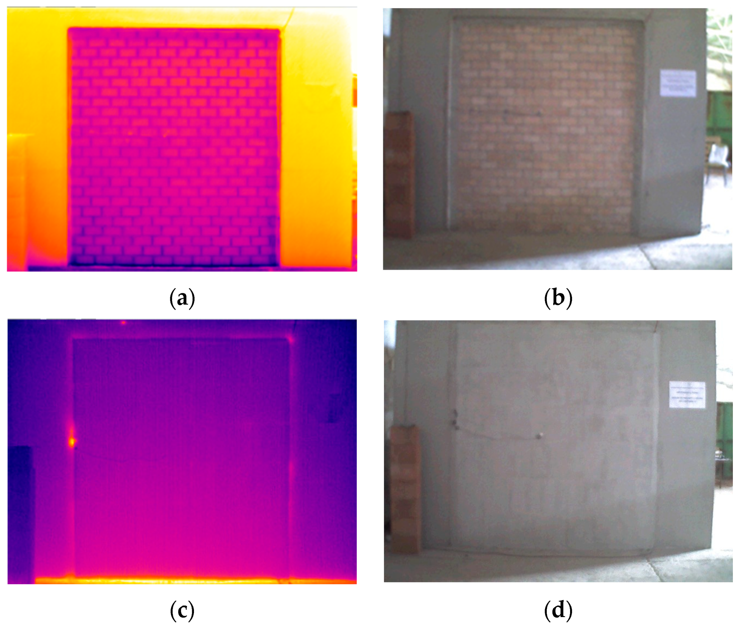
- Infrared thermography (IRT) method to determine appearance of possible thermal bridges in the wall;
- Heat Flow Method was used to estimate the thermal transmittance (U-Value) of the wall;
- Temperature Based Method, a relatively new and simple non-standardized method, was also used to measure the U-value of the observed wall.
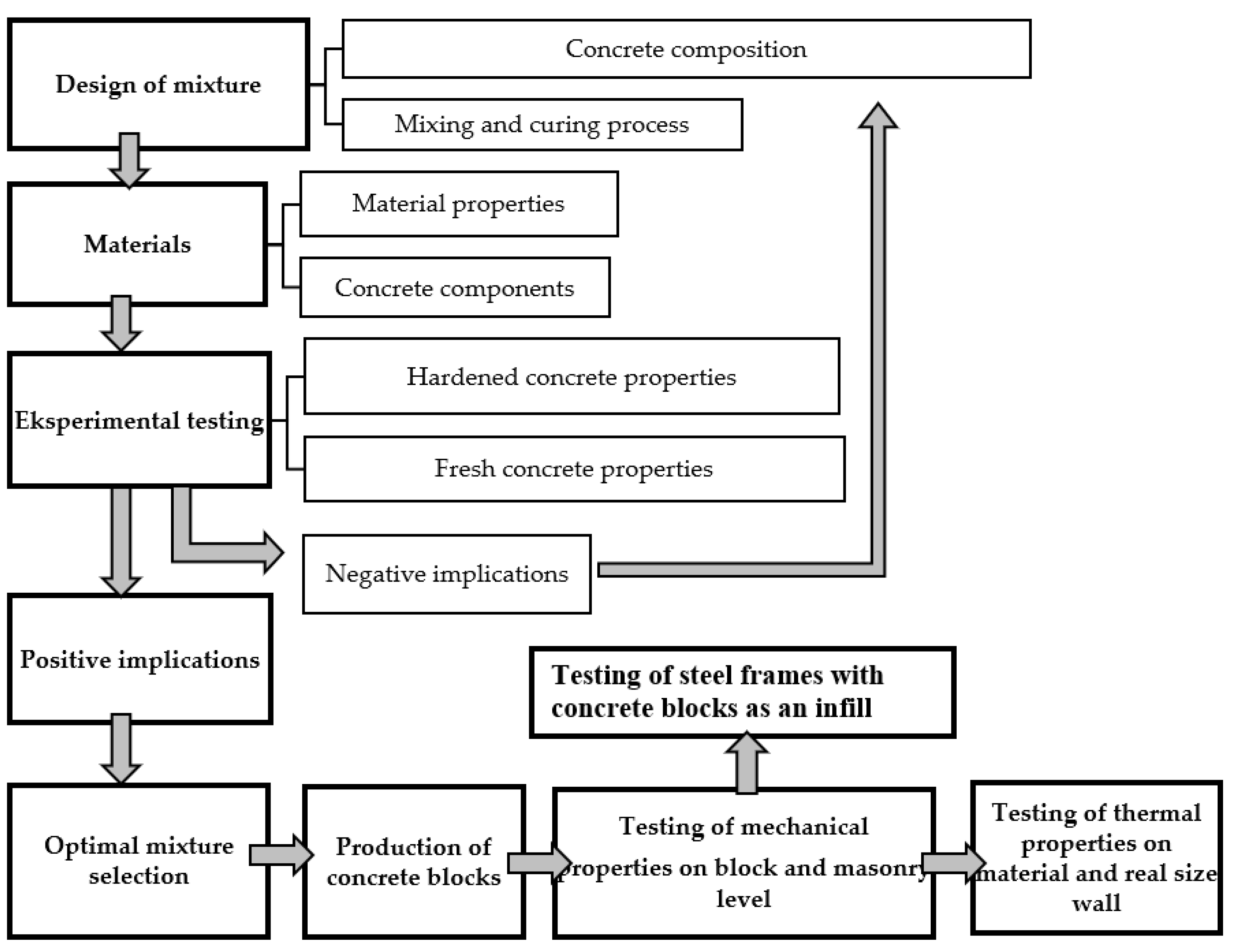
2. Experimental Investigation
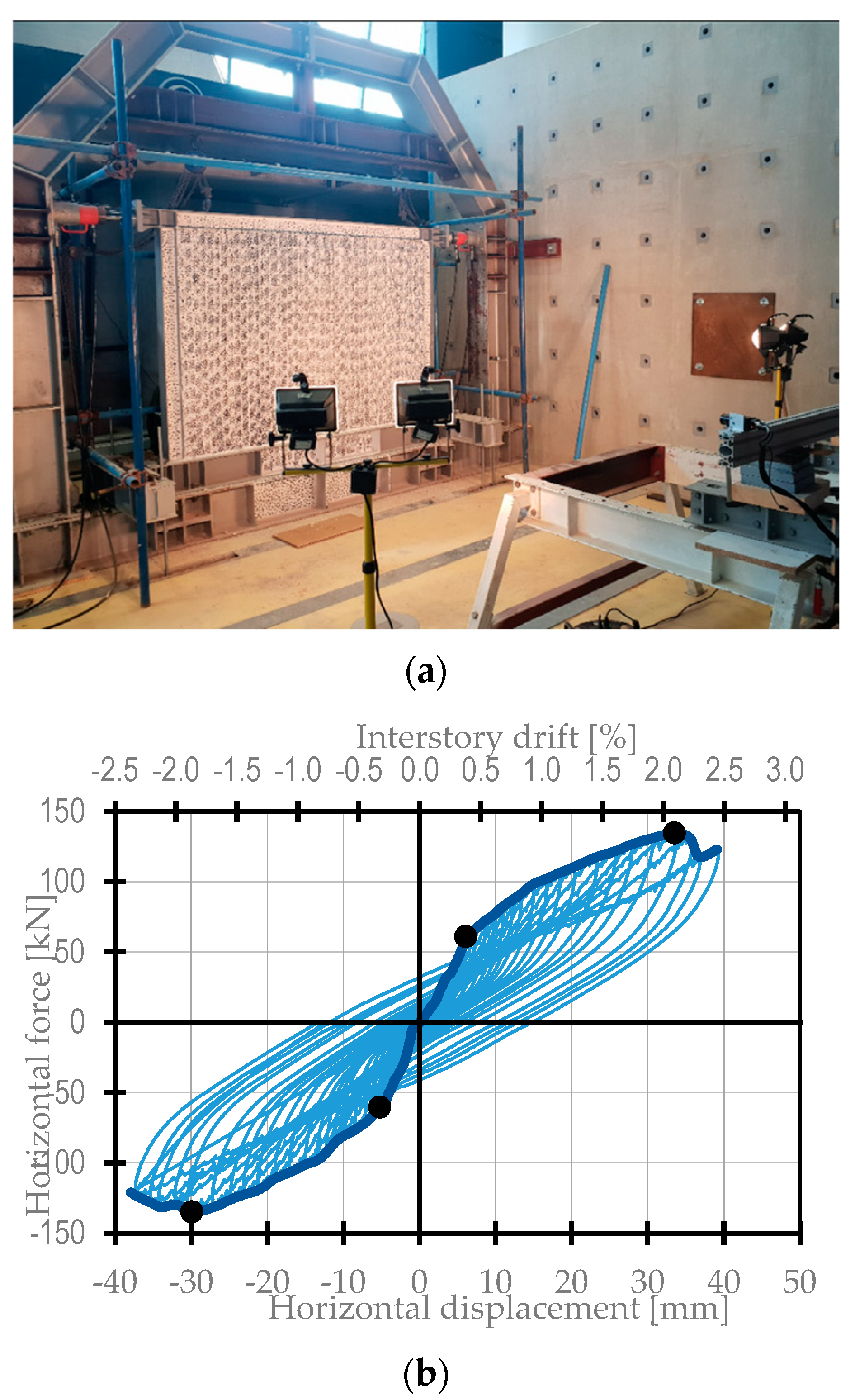
2.1. Previous Experimental Testing
- densities of all mixtures were lower than 2000 kg/m3, thus they were classified as lightweight concretes;
- results of testing confirm that designed mixtures of SCC are of low-strength and stiffness, which was in line with the set objectives.
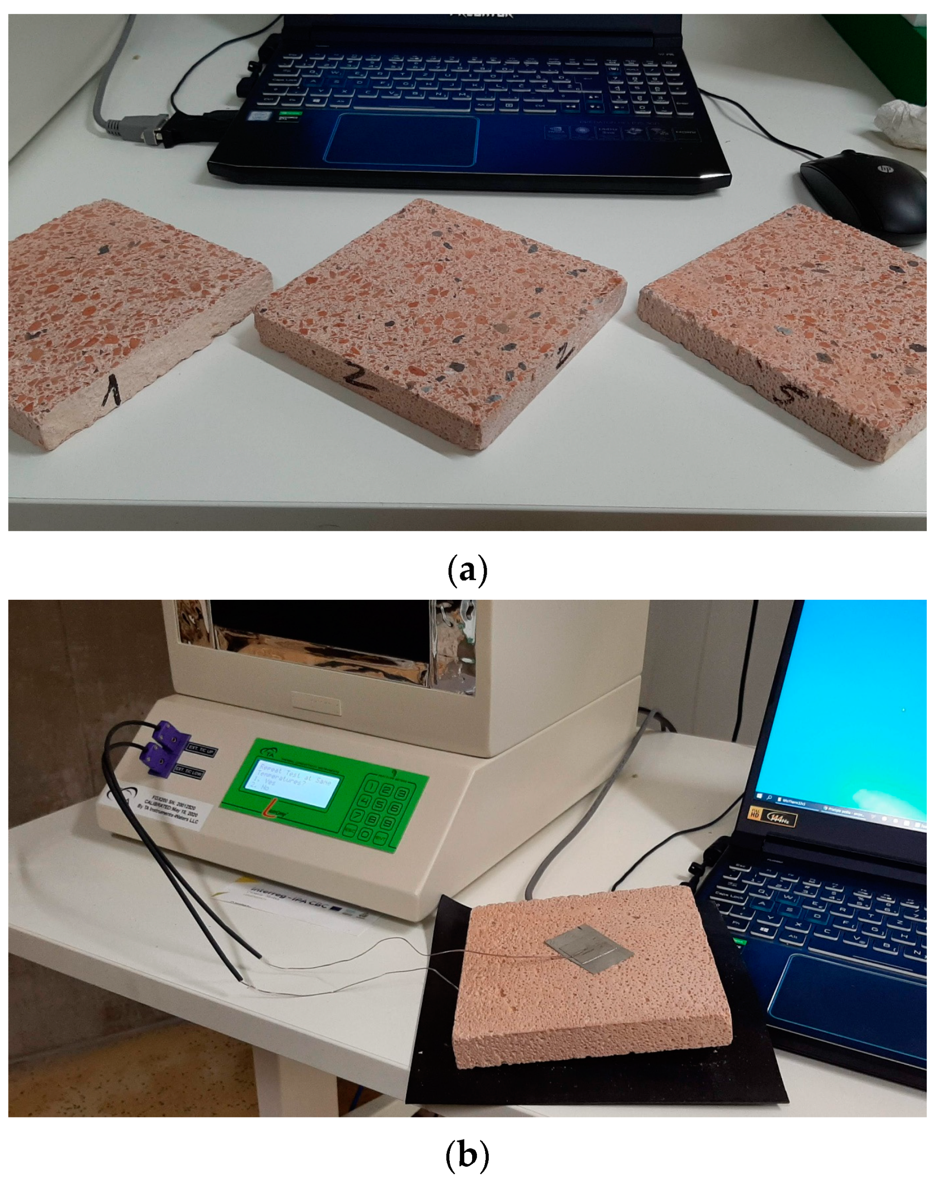
2.2. Measurements of Blocks Thermal Conductivity
- Samples are placed between two plates in the test stack, and a temperature gradient is established over the thickness of the material;
- The plates may be positioned either to a user-defined thickness, or using auto thickness, in which the instrument automatically moves to establish contact with the sample;
- Thermocouples are attached directly to the sample surfaces, eliminating the impact of interface resistance, and improving the measurement accuracy for higher thermal conductivity samples (up to 2.5 W/mK).
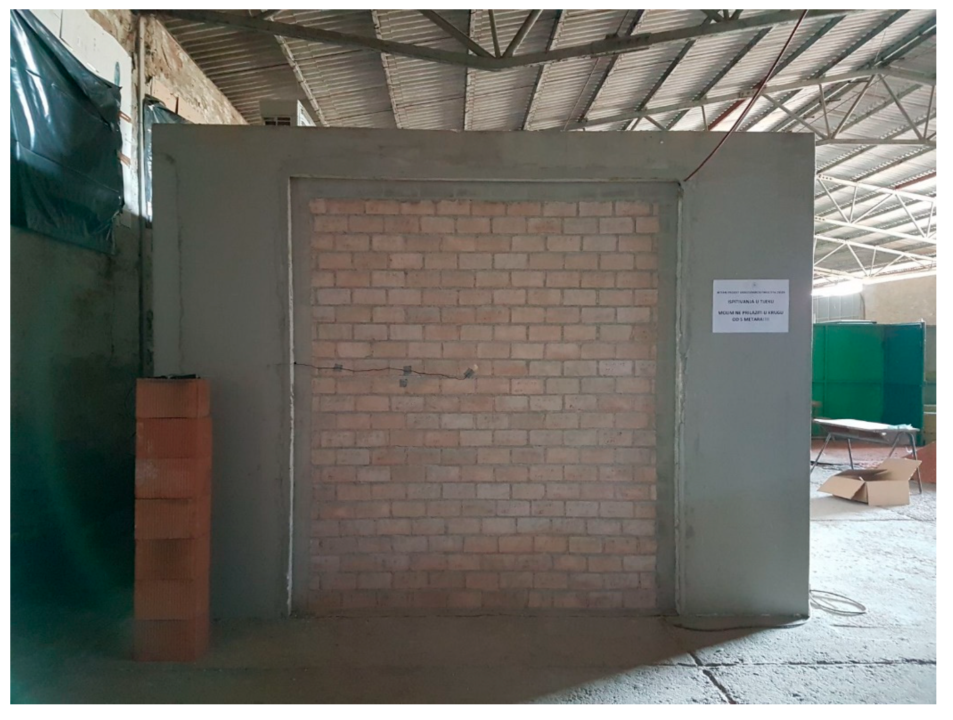
3. In Situ Measurements
3.1. Introduction
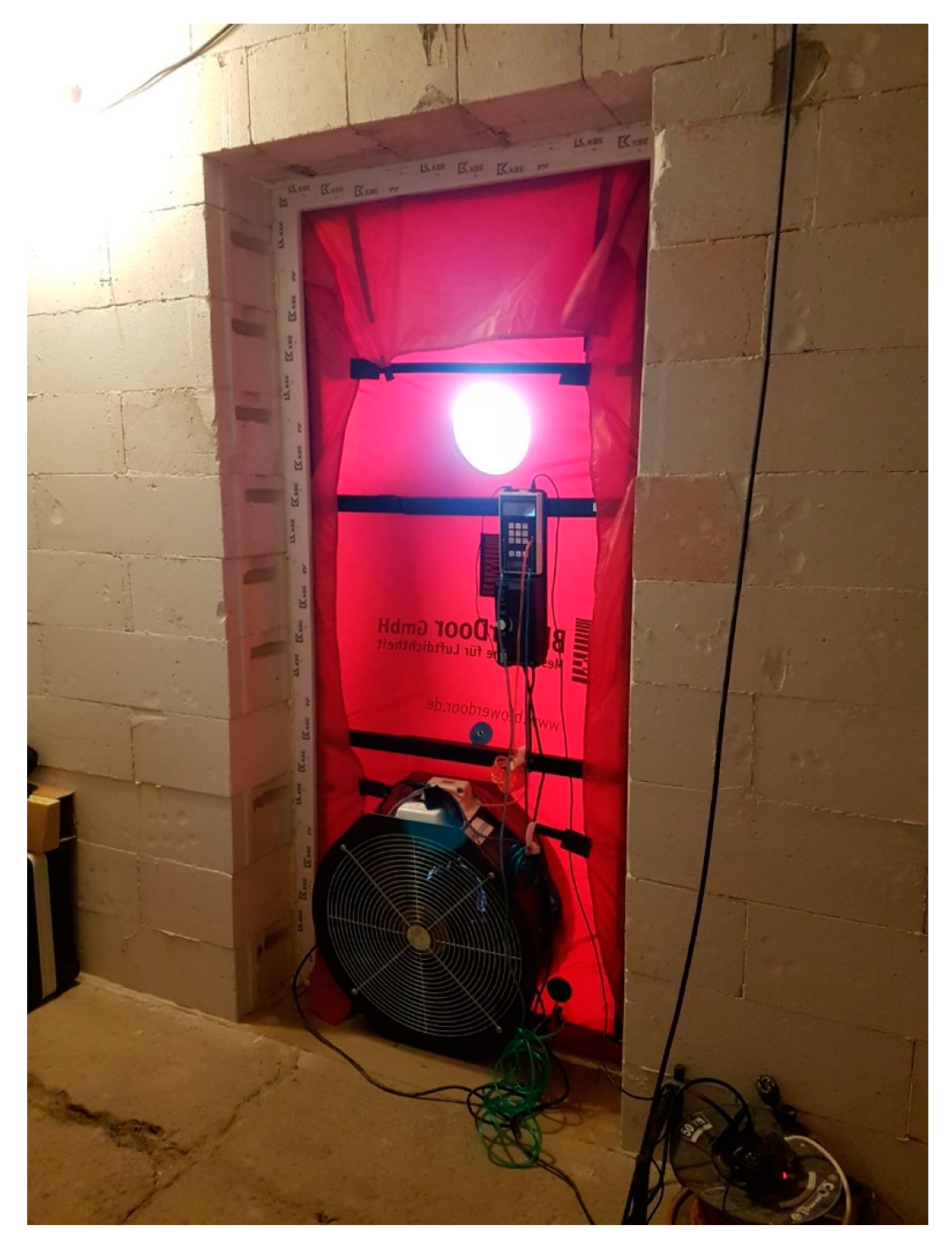
3.2. In-Situ Measurement of Airtightness and Infrared Thermography Method
- All windows, doors, and trapdoors on the envelope are closed;
- Ventilation openings in the envelope for natural ventilation are closed;
- Openings for whole building mechanical ventilation or air conditioning are sealed;
- Other intentional openings in the envelope including intermittent use mechanical ventilation or air conditioning shall be closed;
- Small temperature differences;
- Low wind speeds (wind speed near the ground exceeds 3 m/s, or the meteorological wind speed exceeds 6 m/s).
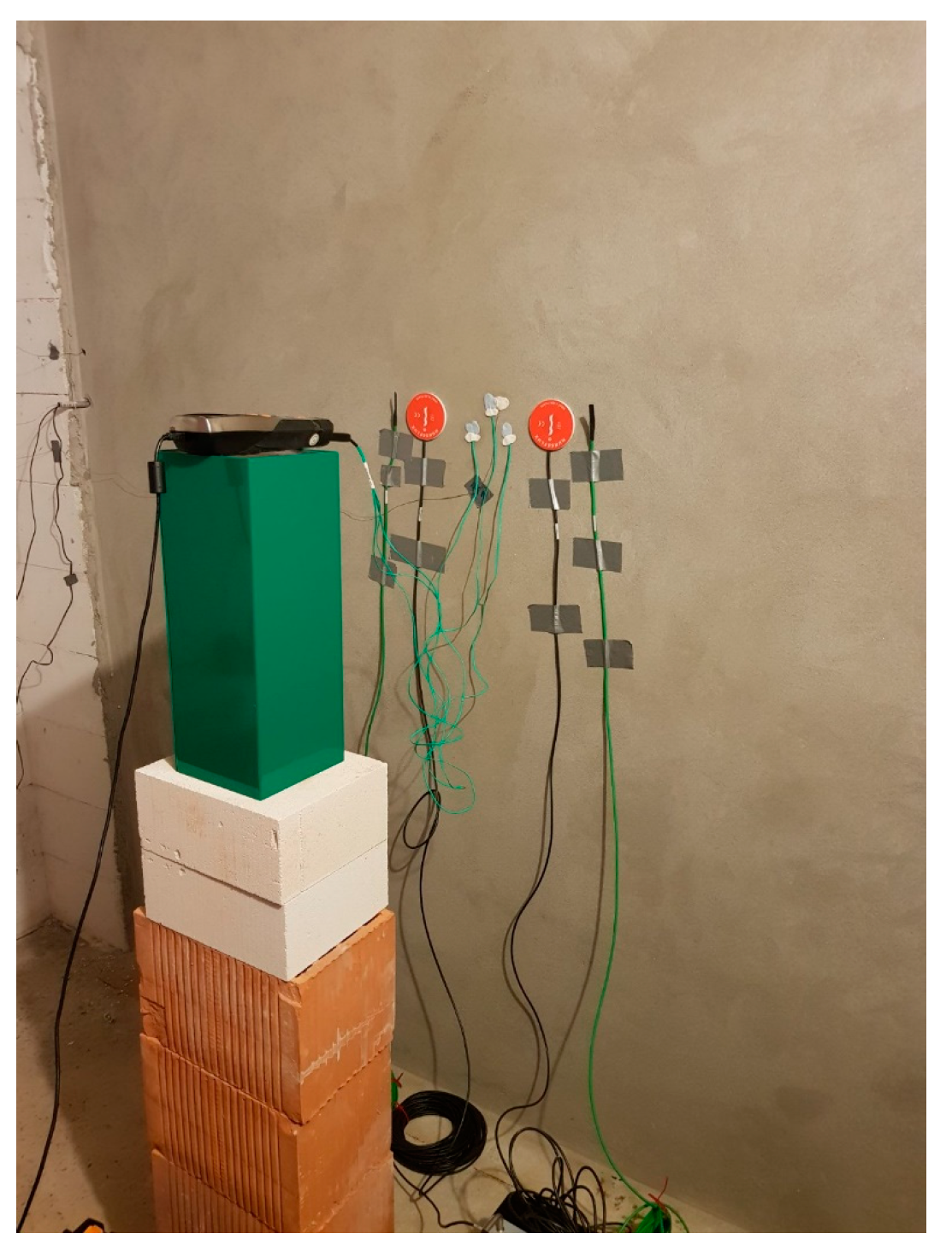
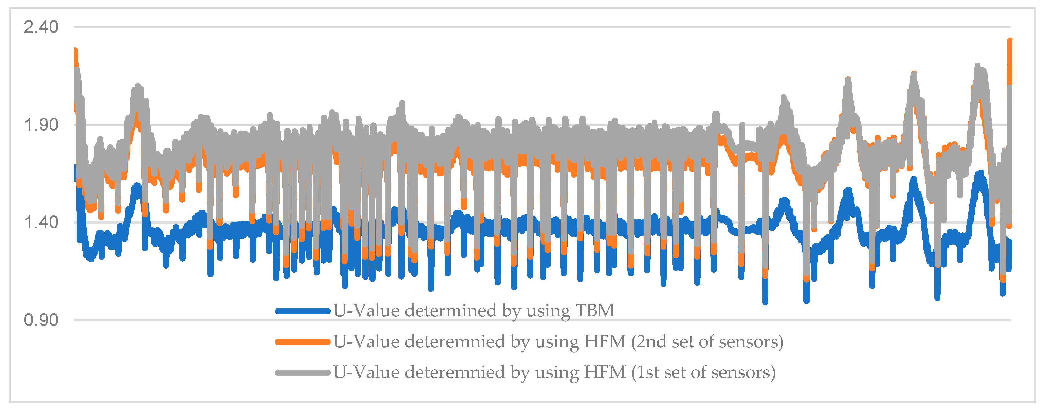
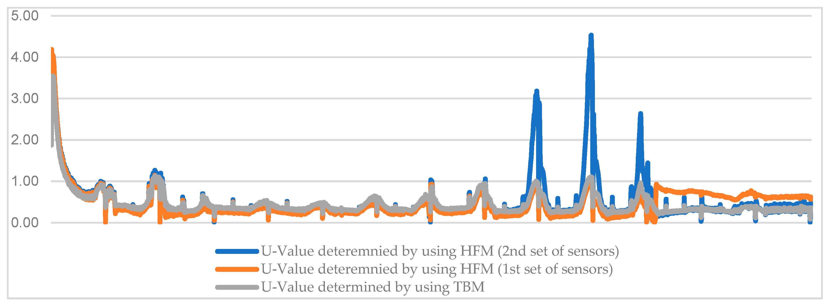
3.3. Measurements of the Thermal Transmission Properties
4. Discussion
- hollow blocks made of lightweight concrete (HBLC), λ = 0.3700 W/mK;
- hollow concrete blocks (HCB), λ = 1.4000 W/mK;
- hollow clay blocks (HCLB), λ = 0.4800 W/mK.
5. Conclusions
- RBC-EP blocks comply to set goals of lower density, stiffness, and strength, combined with robustness and compactness, thus showing potential as an infill material for steel frames;
- The desired structural behavior of steel frames infilled with RBC-EP blocks was experimentally tested and verified—infilled frames showed high ductility and robustness, along with increased strength and stiffness compared to bare steel frames, while, at the same time, preserving the frame from stronger detrimental effects typical for common masonry infill;
- Thermal conductivity of RBC-EP is 0.3774 W/mK, which is similar to lightweight concrete;
- Thermal properties of RBC-EP blocks are better than the thermal properties of commonly in use, HCB and HCLB, and are similar to HBLC;
- Using new hollow masonry RBC-EP blocks does not affect a building’s airtightness values in negative way;
- To avoid the placement of sensors near by the thermal bridges and cracks, IRT should be employed;
- The results of testing TBM in this research suggest that the method is appropriate for isolated walls;
- The experimental heat transfer coefficient of wall constructed with blocks is from 1.363 up to 1.782 W/m2K for an uninsulated wall, and the theoretical value is 2.01 W/m2K, which is better compared to hollow concrete blocks and hollow clay blocks.
Author Contributions
Funding
Institutional Review Board Statement
Informed Consent Statement
Data Availability Statement
Conflicts of Interest
References
- Kolokotsa, D.; Diakaki, C.; Grigoroudis, E.; Stavrakakis, G.; Kalaitzakis, K. Decision support methodologies on the energy efficiency and energy management in buildings. Adv. Build. Energy Res. 2009, 3, 121–146. [Google Scholar] [CrossRef]
- Mickaityte, A.; Zavadskas, E.K.; Kaklauskas, A.; Tupenaite, L. The concept model of sustainable buildings refurbishment. Int. J. Strateg. Property Manag. 2008, 12, 53–68. [Google Scholar] [CrossRef]
- Blanco, J.M.; Frómeta, Y.G.; Madrid, M.; Cuadrado, J. Thermal performance assessment of walls made of three types of sustainable concrete blocks by means of fem and validated through an extensive measurement campaign. Sustainability 2021, 13, 386. [Google Scholar] [CrossRef]
- Sakir, S.; Raman, S.N.; Safiuddin, M.; Kaish, A.B.M.; Mutalib, A.A. Utilization of By-Products and Wastes as Supplementary Cementitious Materials in Structural Mortar for Sustainable Construction. Sustainability 2020, 12, 3888. [Google Scholar] [CrossRef]
- Markulak, D.; Dokšanović, T.; Radić, I.; Miličević, I. Structurally and environmentally favorable masonry units for infilled frames. Eng. Struct. 2018, 175, 753–764. [Google Scholar] [CrossRef]
- Markulak, D.; Dokšanović, T.; Radić, I.; Zovkić, J. Behaviour of steel frames infilled with environmentally and structurally favourable masonry units. Eng. Struct. 2020, 204, 109909. [Google Scholar] [CrossRef]
- Jakumetović, A.; Markulak, D.; Miličević, I. Properties of low strength self-compacting concrete with recycled brick as aggregate. In Proceedings of the 1st International Conference on Construction Materials for Sustainable Future 2017, Zadar, Croatia, 19–21 April 2017; pp. 243–249. [Google Scholar]
- Markulak, D.; Radić, I.; Sigmund, V. Cyclic testing of single bay steel frames with various types of masonry infill. Eng. Struct. 2013, 51, 267–277. [Google Scholar] [CrossRef]
- Pavlu, T.; Fortova, K.; Divis, J.; Hajek, P. The utilization of recycled masonry aggregate and recycled eps for concrete blocks for mortarless masonry. Materials 2019, 12, 1923. [Google Scholar] [CrossRef] [Green Version]
- European Committee for Standardization (CEN). EN 12390-3, Testing Hardened Concrete—Part 3: Compressive Strength of Test Specimens; CEN: Brussels, Belgium, 2009. [Google Scholar]
- European Committee for Standardization (CEN). EN 12390-5, Testing Hardened Concrete—Part 5: Flexural Strength of Test Specimens; CEN: Brussels, Belgium, 2009. [Google Scholar]
- European Committee for Standardization (CEN). EN 12390-7, Testing Hardened Concrete— Part 7: Density of Hardened Concrete; CEN: Brussels, Belgium, 2009. [Google Scholar]
- European Committee for Standardization (CEN). EN 12390-2, Testing Hardened Concrete—Part 2: Making and Curing Specimens for Strength Tests; CEN: Brussels, Belgium, 2009. [Google Scholar]
- Al-Tamimi, A.S.; Al-Amoudi, O.S.B.; Al-Osta, M.A.; Ali, M.R.; Ahmad, A. Effect of insulation materials and cavity layout on heat transfer of concrete masonry hollow blocks. Constr. Build. Mater. 2020, 254, 119300. [Google Scholar] [CrossRef]
- European Committee for Standardization (CEN). EN 772-2, Methods of Test for Masonry Units—Part 2: Determination of Percentage Area of Voids in Aggregate Concrete Masonry Units; CEN: Brussels, Belgium, 1998. [Google Scholar]
- European Committee for Standardization (CEN). EN 772-16, Methods of Test for Masonry Units—Part 16: Determination of Dimensions; CEN: Brussels, Belgium, 2011. [Google Scholar]
- European Committee for Standardization (CEN). EN 12350-6, Testing Fresh Concrete—Part 6: Density; CEN: Brussels, Belgium, 2009. [Google Scholar]
- European Committee for Standardization (CEN). EN 12350-7, Testing Fresh Concrete—Part 7: Air Content—Pressure Methods; CEN: Brussels, Belgium, 2009. [Google Scholar]
- European Committee for Standardization (CEN). EN 12350-8, Testing Fresh Concrete—Part 8: Self-COMPACTING Concrete—Slump-Flow Test; CEN: Brussels, Belgium, 2010. [Google Scholar]
- European Committee for Standardization (CEN). EN 12350-12, Testing Fresh Concrete—Part 12: Self-Compacting Concrete—J-Ring Test; CEN: Brussels, Belgium, 2010. [Google Scholar]
- European Committee for Standardization (CEN). EN 1052-1, Methods of Test for Masonry—Part 1: Determination of compressive Strength; CEN: Brussels, Belgium, 1998. [Google Scholar]
- European Committee for Standardization (CEN). EN 1052-3, Methods of Test for Masonry—Part 3: Determination of Initial Shear Strength; CEN: Brussels, Belgium, 2008. [Google Scholar]
- Madrid, M.; Orbe, A.; Rojí, E.; Cuadrado, J. The effects of by-products incorporated in low-strength concrete for concrete masonry units. Constr. Build. Mater. 2017, 153, 117–128. [Google Scholar] [CrossRef]
- TA Instruments WEB Site. Available online: https://www.tainstruments.com/fox-200/ (accessed on 23 September 2021).
- Mineral Products Association (MPA). Performance of Concrete Structures in Fire; MPA—The Concrete Centre: Maidenhead, UK, 2011; ISBN 978-1-904818-83. [Google Scholar]
- Netinger, I.; Kesegic, I.; Guljas, I. The effect of high temperatures on the mechanical properties of concrete made with different types of aggregates. Fire Saf. J. 2011, 46, 425–430. [Google Scholar] [CrossRef]
- Madrid, M.; Orbe, A.; Carré, H.; García, Y. Thermal performance of sawdust and lime-mud concrete masonry units. Constr. Build. Mater. 2018, 169, 113–123. [Google Scholar] [CrossRef]
- Wakili, K.G.; Tanner, C. U-value of a dried wall made of perforated porous clay bricks: Hot box measurement versus numerical analysis. Energy Build. 2003, 35, 675–680. [Google Scholar] [CrossRef]
- Relander, T.-O.; Holøs, S.; Thue, J.V. Airtightness estimation—A state of the art review and an en route upper limit evaluation principle to increase the chances that wood-frame houses with a vapour- and wind-barrier comply with the airtightness requirements. Energy Build. 2012, 54, 444–452. [Google Scholar] [CrossRef]
- ISO 9972:2015. Thermal Performance of Buildings—Determination of Air Permeability of Buildings—Fan Pressurization Method; ISO: Geneva, Switzerland, 2015. [Google Scholar]
- Sfakianaki, A.; Pavlou, K.; Santamouris, M.; Livada, I.; Assimakopoulos, M.N.; Mantas, P.; Christakopoulos, A. Air tightness measurements of residential houses in Athens, Greece. Build. Environ. 2008, 43, 398–405. [Google Scholar] [CrossRef]
- Fokaides, P.A.; Kalogirou, S.A. Application of infrared thermography for the determination of the overall heat transfer coefficient (U-Value) in building envelopes. Appl. Energy 2011, 88, 4358–4365. [Google Scholar] [CrossRef]
- Fox, M.; Goodhew, S.; De Wilde, P. Building defect detection: External versus internal thermography. Build. Environ. 2016, 105, 317–331. [Google Scholar] [CrossRef] [Green Version]
- Kalamees, T. Air tightness and air leakages of new lightweight single-family detached houses in Estonia. Build. Environ. 2007, 42, 2369–2377. [Google Scholar] [CrossRef]
- Taylor, T.; Counsell, J.; Gill, J. Energy efficiency is more than skin deep: Improving construction quality control in new-build housing using thermography. Build. Environ. 2013, 66, 222–231. [Google Scholar] [CrossRef]
- Gonçalves, M.D.; Colantonio, T. Commissioning of Exterior Building Envelopes of Large Buildings for Resultant Moisture Accumulation Using Infrared Thermography and Other Diagnostic Tools. Therm. Perform. Exter. Envel. 2007, 7, 1–10. [Google Scholar]
- Lerma, C.; Barreira, E.; Almeida, R.M.S.F. A discussion concerning active infrared thermography in the evaluation of buildings air infiltration. Energy Build. 2018, 168, 56–66. [Google Scholar] [CrossRef]
- Kilic, G. Using advanced NDT for historic buildings: Towards an integrated multidisciplinary health assessment strategy. J. Cult. Herit. 2015, 16, 526–535. [Google Scholar] [CrossRef]
- Titman, D.J. Applications of thermography in non-destructive testing of structures. NDT E Int. 2001, 34, 149–154. [Google Scholar] [CrossRef]
- Hopper, J.; Littlewood, J.R.; Taylor, T.; Counsell, J.A.; Thomas, A.M.; Karani, G.; Evans, N.I. Assessing retrofitted external wall insulation using infrared thermography. Struct. Surv. 2012, 30, 245–266. [Google Scholar] [CrossRef]
- Taileb, A.; Dekkiche, H. Infrared imaging as a means of analyzing and improving energy efficiency of building envelopes: The case of a LEED Gold Building. Procedia Eng. 2015, 118, 639–646. [Google Scholar] [CrossRef]
- de Freitas, S.S.; de Freitas, V.P.; Barreira, E. Detection of façade plaster detachments using infrared thermography—A nondestructive technique. Constr. Build. Mater. 2014, 70, 80–87. [Google Scholar] [CrossRef]
- Kominsky, J.R.; Luckino, J.; Martin, T. Passive infrared thermography—a qualitative method for detecting moisture anomalies in building envelopes. Tedford Pond 2007, 2005, 1–11. [Google Scholar]
- Barreira, E.; Almeida, R.M.S.F.; Delgado, J.M.P.Q. Infrared thermography for assessing moisture related phenomena in building components. Constr. Build. Mater. 2016, 110, 251–269. [Google Scholar] [CrossRef]
- Grinzato, E.; Bison, P.G.; Marinetti, S. Monitoring of ancient buildings by the thermal method. J. Cult. Herit. 2002, 3, 21–29. [Google Scholar] [CrossRef]
- Edis, E.; Flores-Colen, I.; De Brito, J. Building thermography: Detection of delamination of adhered ceramic claddings using the passive approach. J. Nondestr. Eval. 2014, 34, 268. [Google Scholar] [CrossRef]
- Walker, R.; Pavía, S. Thermal performance of a selection of insulation materials suitable for historic buildings. Build. Environ. 2015, 94, 155–165. [Google Scholar] [CrossRef]
- International Organization for Standardization. Thermal Insulation—Building Elements—In-Situ Measurement of Thermal Resistance and Thermal Transmittance—Part 1: Heat Flow Meter Method; ISO: Geneva, Switzerland, 2014. [Google Scholar]
- Thermal Performance of Buildings—Qualitative Detection of Thermal Irregularities in Building Envelopes—Infrared Method; ISO: Geneva, Switzerland, 1983.
- Kylili, A.; Fokaides, P.A.; Christou, P.; Kalogirou, S.A. Infrared thermography (IRT) applications for building diagnostics: A review. Appl. Energy 2014, 134, 531–549. [Google Scholar] [CrossRef]
- Trethowen, H. Measurement errors with surface-mounted heat flux sensors. Build. Environ. 1986, 21, 41–56. [Google Scholar] [CrossRef]
- Çengel, Y.A. Heat Transfer: A Practical Approach; McGraw-Hill: New York, NY, USA, 2004. [Google Scholar]
- Teni, M.; Krstić, H.; Kosiński, P. Review and comparison of current experimental approaches for in-situ measurements of building walls thermal transmittance. Energy Build. 2019, 203, 109417. [Google Scholar] [CrossRef]
- Narodne Novine. Tehnički Propis o Racionalnoj Uporabi Energije i Toplinskoj Zaštiti u Zgradama (Translation: Technical Regulation on the Rational Use of Energy and Thermal Insulation in Buildings); Narodne Novine: Zagreb, Croatia, 2020. [Google Scholar]


| Composition (kg/m3) | Fresh state | Viscosity Class | VS2 | ||
| w/b | 0.47 | Density ρ (kg/m3) | 1730 | ||
| w/p | 0.99 | Air content (%) | 8.0 | ||
| Cement | 200 | Slump-flow test T500 (s) | 4.8 | ||
| Lime | 255 | J-ring test (mm) | 9.25 | ||
| Water | 215 | Hardened state | Density class | D.1.4 | |
| Additive | SP | 2% | CS fc (MPa) | 5.36 | |
| VMA | 0.5% | FS fcf (MPa) | 2.34 | ||
| AEA | 1% | Density ρ (kg/m3) | 1396 | ||
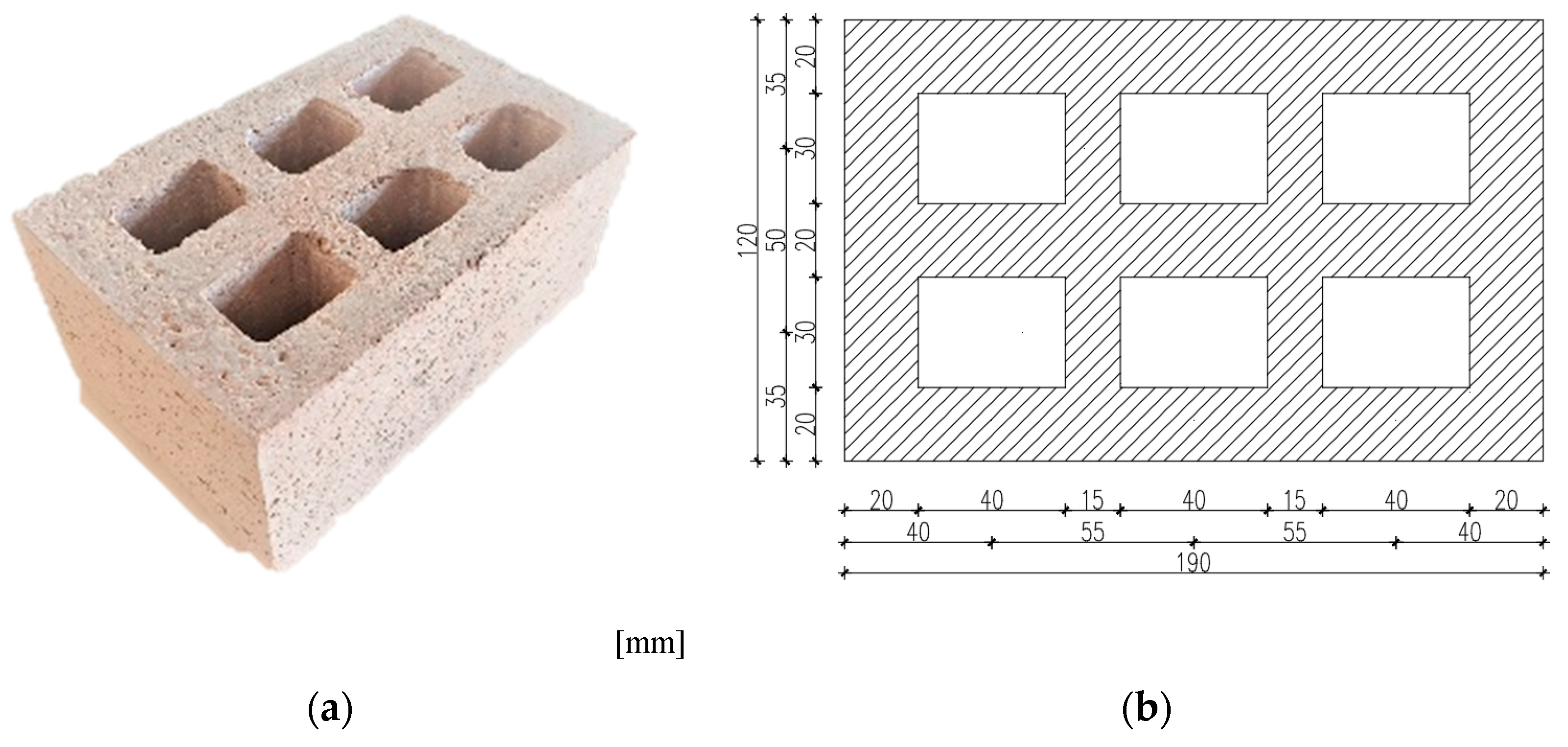
| Filler | BP | 137 | Concrete masonry unit RBC-EP | Dimensions (mm) | 190 × 120 × 90 |
| Fine | RB | 346 | Mean compressive strength fm (MPa) | 4.06 | |
| GEP | 9.6 | Normalized compressive strength fb (MPa) | 2.99 | ||
| Coarse | RB | 262 | Mean gross dry density (kg/m3) | 847.95 | |
| Test Configuration | ISF-RBC-EP | ||
|---|---|---|---|
| Loading direction | + | − | |
| Initial stiffness | S0 (kN/mm) | 14.4 | 15.7 |
| Change of initial stiffness | Fy (kN) | 69.5 | 69.0 |
| dy (mm) | 8.1 | 7.6 | |
| DRy (%) | 0.5 | 0.5 | |
| Ultimate load | Fu (kN) | 130.0 | 130.0 |
| du (mm) | 48.7 | 30.2 | |
| DRu (%) | 3.0 | 1.9 | |
| Ultimate drift | Fdmax (kN) | 130.0 | 90.0 |
| dmax (mm) | 48.7 | 37.1 | |
| DRdmax (%) | 3.0 | 2.3 | |
| Values | Sample 1 | Sample 2 | Sample 3 |
|---|---|---|---|
| Setpoint Upper Plate | 15.00 °C | 15.00 °C | 15.00 °C |
| Setpoint Lower Plate | 25.00 °C | 25.00 °C | 25.00 °C |
| Results Average-Thermal conductivity [W/mK] Temperature Average 20 °C | 0.3817 | 0.3807 | 0.3835 |
| Results Average - Thermal conductivity [W/mK] Temperature Average 15 °C | 0.3787 | 0.3773 | 0.3800 |
| Results Average-Thermal conductivity [W/mK] Temperature Average 10 °C | 0.3762 | 0.3743 | 0.3776 |
| Average value of Thermal conductivity [W/mK] | 0.3789 | 0.3774 | 0.3804 |
| Wall Type | Measurement Period | HFM Method Sensor Set 1 | HFM Method Sensor Set 2 | TBM | Theoretical U-Value |
|---|---|---|---|---|---|
| U [W/m2K] | |||||
| Uninsulated wall composition: 1 cm thick plaster (λplaster = 1.000 W/mK) 12 cm thick wall (λblock = 0.3789 W/mK) | 10.1.2020.–24.1.2020. | 1.740 | 1.782 | 1.363 | 2.01 |
| Wall with thermal insulation composition: 1 cm thick plaster (λplaster = 1.000 W/mK) 12 cm thick wall (λblock = 0.3789 W/mK) 10 cm thick insulation (λMW = 0.035 W/mK) | 10.3.2020.–24.3.2020. | 0.516 | 0.465 | 0.457 | 0.30 |
| Difference in values on uninsulated and insulated wall [%] | 70% | 74% | 66% | 85% | |
| Type of Block–Vertical Hollows | Dimensions (mm) | Normalized Compressive Strength fb (MPa) | Thermal Conductivity (W/mK) | Weight (kg/unit) | Overall Mass of 1 m3 of Wall (kg) |
|---|---|---|---|---|---|
| Hollow clay blocks (HCLB) | 250 × 190 × 190 | 6.51 | 0.4800 | 14 | 1554 |
| Hollow blocks made of lightweight concrete (HBLC) | 625 × 200 × 100 | 2.60 | 0.3700 | 10 | 800 |
| Hollow concrete blocks (HCB) | 200 × 200 × 400 | 6.50 | 1.4000 | 17 | 1071 |
| Concrete with recycled crushed brick and ground polystyrene (RBC-EP) | 190 × 120 × 90 | 2.99 | 0.3789 | 2.50 | 1220 |
| Wall Type | Masonry Wall–RBC-EP Block | Masonry Wall–HBLC | Masonry Wall–HCB | Masonry Wall–HCLB |
|---|---|---|---|---|
| Theoretical U-Value [W/m2K] for Uninsulated Wall | 2.01 | 1.98 | 3.76 | 2.33 |
| Theoretical U-Value [W/m2K] for Insulated Wall | 0.30 | 0.30 | 0.32 | 0.30 |
Publisher’s Note: MDPI stays neutral with regard to jurisdictional claims in published maps and institutional affiliations. |
© 2021 by the authors. Licensee MDPI, Basel, Switzerland. This article is an open access article distributed under the terms and conditions of the Creative Commons Attribution (CC BY) license (https://creativecommons.org/licenses/by/4.0/).
Share and Cite
Krstić, H.; Miličević, I.; Markulak, D.; Domazetović, M. Thermal Performance Assessment of a Wall Made of Lightweight Concrete Blocks with Recycled Brick and Ground Polystyrene. Buildings 2021, 11, 584. https://doi.org/10.3390/buildings11120584
Krstić H, Miličević I, Markulak D, Domazetović M. Thermal Performance Assessment of a Wall Made of Lightweight Concrete Blocks with Recycled Brick and Ground Polystyrene. Buildings. 2021; 11(12):584. https://doi.org/10.3390/buildings11120584
Chicago/Turabian StyleKrstić, Hrvoje, Ivana Miličević, Damir Markulak, and Mihaela Domazetović. 2021. "Thermal Performance Assessment of a Wall Made of Lightweight Concrete Blocks with Recycled Brick and Ground Polystyrene" Buildings 11, no. 12: 584. https://doi.org/10.3390/buildings11120584
APA StyleKrstić, H., Miličević, I., Markulak, D., & Domazetović, M. (2021). Thermal Performance Assessment of a Wall Made of Lightweight Concrete Blocks with Recycled Brick and Ground Polystyrene. Buildings, 11(12), 584. https://doi.org/10.3390/buildings11120584