Article

Bond of Ribbed Steel Bar in High-Performance Steel Fiber Reinforced Expanded-Shale Lightweight Concrete

1
International Joint Research Lab for Eco-building Materials and Engineering of Henan, School of Civil Engineering and Communications, North China University of Water Resources and Electric Power, Zhengzhou 450045, China
2
Collaborative Innovation Center for Efficient Utilization of Water Resources, North China University of Water Resources and Electric Power, Zhengzhou 450045, China
3
School of Building Engineering, Zhengzhou Business University, Zhengzhou 451200, China
*
Authors to whom correspondence should be addressed.
Buildings 2021, 11(12), 582; https://doi.org/10.3390/buildings11120582
Submission received: 20 October 2021 / Revised: 21 November 2021 / Accepted: 22 November 2021 / Published: 25 November 2021
(This article belongs to the Collection Advanced Concrete Materials in Construction)

Abstract

:
For the structural application of high-performance Steel Fiber Reinforced Expanded-shale Lightweight Concrete (SFRELC), a reliable bond of ribbed steel bar should be ensured. In this paper, an experimental study was carried out on the bond properties of ribbed steel bar embedded in SFRELC by the direct pull-out test. The SFRELC was produced with a strength grade of 35 MPa and a volume fraction of steel fiber as 0%, 0.8%, 1.2%, 1.6% and 2.0%, respectively. Fifteen groups of specimens were made with a central placed steel bar with diameter of 14 mm, 20 mm and 28 mm, respectively. Complete bond stress-slip curves were determined for each group of specimens, and the characteristic values of bond-stress and slip at key points of the curves were ascertained. Results show that the bond strength, peak-slip and residual bond strength increased with the increase of the volume fraction of steel fiber. With the increase of steel bar diameter, bond strength decreased while the peak-slip increased, and the descending curves became sharp with a decreased residual bond strength. Formulas for calculating the bond strength and peak-slip were proposed. The relationships were determined for the splitting bond strength, residual bond strength with the bond strength, the splitting bond slip and residual bond slip with the peak-slip. Combined with rational fitting analyses of bond strength and slip, a constitutive model was selected for predicting the bond stress-slip of ribbed steel bar in SFRELC.

1. Introduction

Bond performance of ribbed steel bar embedded in concrete is a foundation ensuring the joint work of these two kinds of materials. This is also a basic issue for the structural application of lightweight aggregate concrete (LAC) [1]. Inherently, the bond usually comes from the chemical force, the friction force and the mechanical bite force along the interface between steel bar and LAC. They are always affected by the macro factors, including the concrete composition, the geometry and surface characteristic of steel bar, the position and net spacing of steel bars, the thickness of concrete cover and the transverse confinement [2,3].
The methods of a direct pull-out test and beam test are mainly used to measure the bond property [4]. By using the pull-out test, bond behaviors such as bond strength, slip and bond stress-slip relationship of ribbed steel bar in LAC have been studied. Zhang et al. [2] reported that the bond strength and the peak-slip respectively increased by 58.4% and 78.2% when the LAC strength increased from 21.2 MPa to 42.3 MPa; the bond strength increased by 9.2% and the peak-slip decreased by 19.3% when the diameter of steel bar varied from 12 mm to 25 mm; and the bond strength and the peak-slip respectively increased by 28.2% and 61.7% when the thickness of LAC cover increased from 32 mm to 67 mm. Lachemi et al. [3] reported that the bond strength increased by 65.7% and 9.2% for steel bar in LAC with strength grade of 30 MPa and 40 MPa when the thickness of LAC cover increased from 20 mm to 42 mm, while the bond strength decreased by 16–58% when the bond length increased from 60 mm to 320 mm, and decreased by 54–68% when the diameter of steel bar increased from 8 mm to 28 mm. In the case of steel bar with diameters of 12 mm–25 mm, the bond strength increased by 26–69% when the strength grade of LAC changed from 30 MPa to 40 MPa. The reduction of stirrup spacing and the raise of the reinforcement ratio also improved the bond strength of ribbed steel bar in LAC [3,4,5]. With the stirrup spacing decreased from 100 mm to 50 mm, the bond strength increased by about 9.8%. With the reinforcement ratio changed from 0.67% to 1.0%, the bond strength increased by about 8.1%.
Three kinds of failure modes, including splitting, shearing and pull-out, could happen on the specimens of ribbed steel bar embedded in LAC. Specimens without any transversal restraints usually present a splitting failure, with the LAC cracked into several pieces, and the complete bond stress-slip curves are difficult to measure due to the brittle damage. The LAC cracks can be restrained by the stirrups configured in the specimen to bear the circumferential tensile stress of LAC. This improves the bond stress and modifies the failure mode from split to shear to a certain degree [5,6]. In case of pull-out failure of test specimens, the bond strength presented a better relationship to the tensile strength than the compressive strength of LAC [4,5,6,7], and the peak-slip corresponding to the bond strength increased with the diameter of steel bar and mainly influenced by the ratio c/d of concrete cover to diameter of steel bar [2,8,9]. Commonly, the bond stress-slip curve is always predicted by different formulas for the ascending portion and descending portion. In specifications of Fib Model Code 2010 and China code GB 50010, the polylines are used to express the descending portion with different shape of test curves [10,11]. In some prediction models, the ascending curve is also divided into several parts such as micro-slip stage, slip stage and splitting stage [12,13,14]. Meanwhile, some simple models were also proposed, and the ascending and descending portions are each expressed by a formula [15,16].
On the basis of above studies, the splitting failure of specimens can be avoided by the presence of steel fibers in LAC, due to the confinement to transversal deformation and the improvement of tensile strength of LAC by steel fibers. Bond strength of steel bar in LAC with hook-end steel fiber increased by about 16.3% when the aspect ratio of steel fiber changed from 50 to 80 and increased by about 64–75% when the volume fraction of steel fiber increased from 0% to 1.5% [7,17,18,19]. As the specimens remained intact or even did not crack, the steel bar was pulled out of the LAC with the increasing content of steel fibers, and a complete bond stress-slip curve was obtained [7,20]. This makes the steel fiber play a good role on the strengthening of the bond property.
Comparatively, short studies were carried out on the bond property of steel bar in LAC with steel fibers. For the reliable application in structural engineering of a new steel fiber reinforced expanded-shale lightweight concrete (SFRELC) [21,22,23], the bond performance of steel bar in SFRELC should be determined. This is a key issue of a new material before it can be used for structural application. Therefore, in this paper, considering the main factors of the volume fraction of steel fiber and the diameter of hot-rolled ribbed steel bar, 15 groups of specimens were prepared and tested under the central pull-out test. The complete bond stress-slip curves were recorded, and the bond strength and peak-slip as well as the bond stress and slip at other key points of the curves were obtained from the test curves. Based on the test results, fitting analyses were performed to get the formulas of bond stress and slip at these key points, which represent different bonding ability with the loading process. Finally, the test curves were compared with the calculation results of existing formulas proposed in the literature [10,12,13,14,15,16], and a model was selected for predicting the bond stress-slip of ribbed steel bar in SFRELC.

2. Materials and Methods
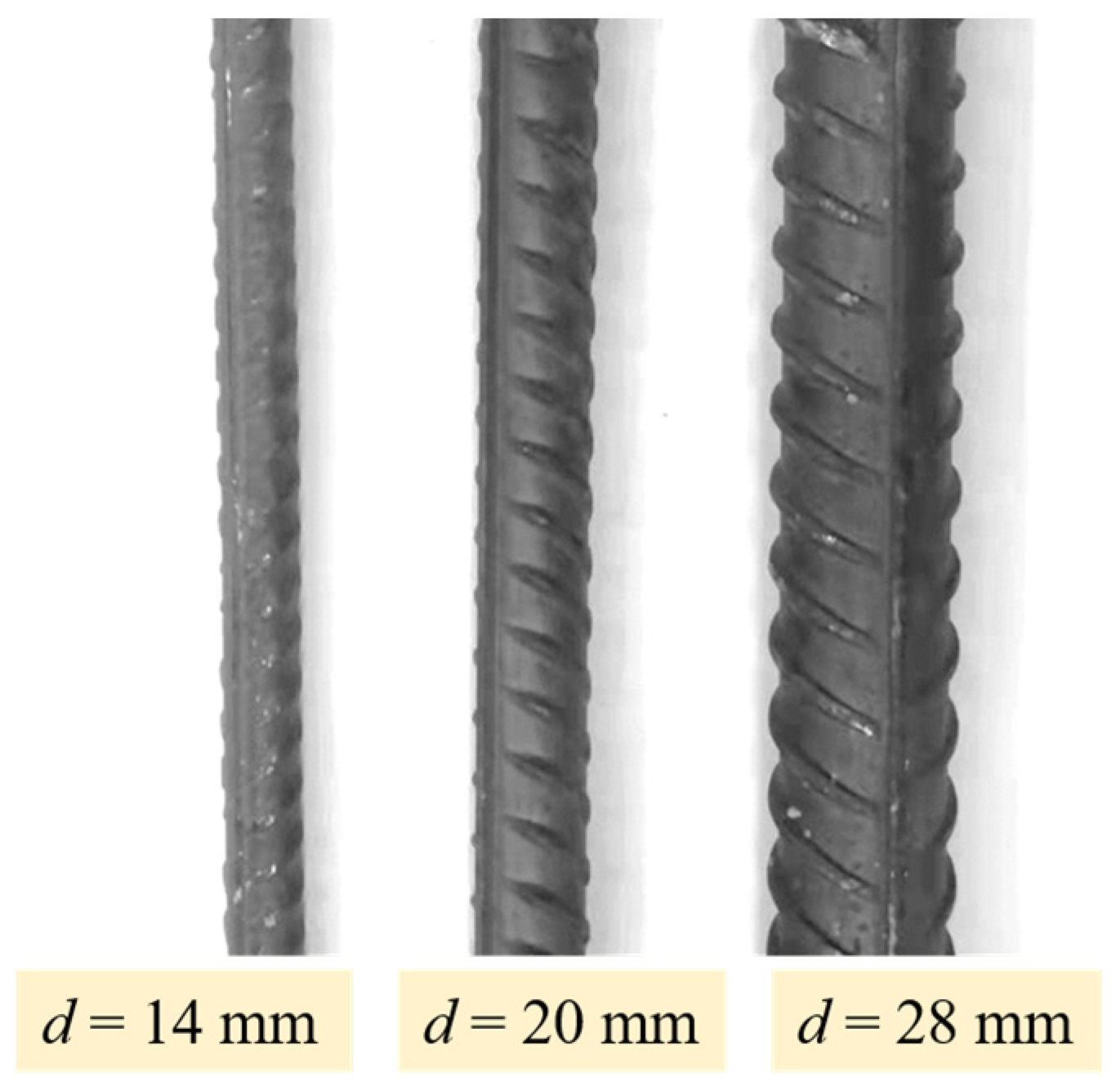
2.1. Specimens

The specimens for pull-out test were made with hot-rolled ribbed steel bar embedded centrally in SFRELC block. The bond length of steel bar embedded in SFRELC was 5 times of the diameter of steel bar, that is, lb = 5d. This length is adaptable to lead a uniform bond stress [7,12]. To prevent the cracking of SFRELC around the steel bar, the thickness of SFRELC cover was designed as 6d. Both ends of steel bar embedded in SFRELC were free with 50 mm long by the package of PVC sleeves. Each sleeve was 80 mm long and sealed with paraffin. This was to eliminate the free surface influence and the concentrated compression on load surface of SFRELC block. As presented in Figure 1, the section of SFRELC block was (13d × 13d) mm and the length was (5d + 100) mm. Concretely, the blocks were 182 mm × 182 mm × 170 mm, 260 mm × 260 mm × 200 mm, and 364 mm × 364 mm × 240 mm, respectively for the embedded steel bars with diameter d = 14 mm, 20 mm and 28 mm. Thirty specimens were totally cast, and two of them were the same as a group for the replicate tests. After staying in formwork for 24 h, the blocks were demolded and wet cured for 7 days, and then placed indoors for 20 days before testing.

2.2. Materials

The steel bar was HRB400 hot-rolled ribbed steel bar with diameter d = 14 mm, 20 mm and 28 mm as shown in Figure 2. The outline dimension and the mechanical properties tested according to China Code GB/T 228 [24], are presented in Table 1.
The cement was Portland cement in strength grade of 42.5; the physical and mechanical properties are presented in Table 2. Class-II fly ash was used for a mineral admixture with physical properties as presented in Table 3. The high-strength sintering expanded shales in continuous gradation with particles of 0–2 mm and 2–16 mm were used as the fine and coarse aggregates. The physical and mechanical properties are presented in Table 4, which met the specification of China code GB/T 17431.2 [25]. The milling steel fiber was used with length lf = 32 mm, equivalent diameter df = 0.8 mm and aspect ratio lf/df = 40. Other materials were the polycarboxylic acid superplasticizer with water-reducing rate no less than 30% and the tap water.
The mix proportion of high-performance SFRELC was designed by the absolute volume method as per China Code JGJ/T12, and the sand ratio increased with the volume fraction of steel fiber by replacing the expanded-shale with equal mass of steel fiber [21,26,27]. As presented in Table 5, the strength grade of SFRELC without steel fiber was 30 MPa, and the target cubic compressive strength was 38 MPa. This required the water to binder ratio w/b = 0.31. The dosage of raw materials changed with the volume fraction of steel fiber vf = 0.8%, 1.2%, 1.6% and 2.0%. On the premise of the surface dry saturated condition of aggregates for mix proportion design, additional water should be added due to the water absorption of aggregates during the mixing. In this study, it was determined by the 1 h water absorption of the ceramsite sand and expanded-shale.
All mixing and the preparation of specimens were done in the lab. The lightweight aggregates were wet-processed with the additional water for 1 hour in a horizontal shaft forced-mixer. Then the cement, fly ash, mix water and water reducer were successively added and mixed uniformly in the mixer. After that, the steel fiber was added and uniformly mixed. The workability of fresh SFRELC was measured by the slump method as per China Code GB50080 [28]. All mixtures were good without bleeding. The slumps of mixtures reduced with the increase of the volume fraction of steel fiber. This is a result of the overlap effect of steel fibers. As previous studies showed [29,30,31], this effect will be weakened by the vibration and less influenced on the forming of SFRELC.
For each trial of the specimens, 9 cubes with dimension of 150 mm and 6 prisms with dimension of 150 mm × 150 mm × 300 mm were cast and cured at the same condition of SFRELC blocks for the measurement of basic mechanical properties of SFRELC. Three cubes as a group were tested respectively for the cubic compressive strength fcu, the splitting tensile strength fst and the apparent dry density ρd. Three prisms as a group were tested respectively for the axial compressive strength fc and the modulus of elasticity Ec. Results are presented in Table 6.

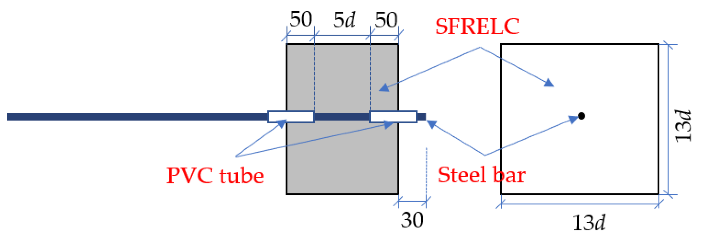
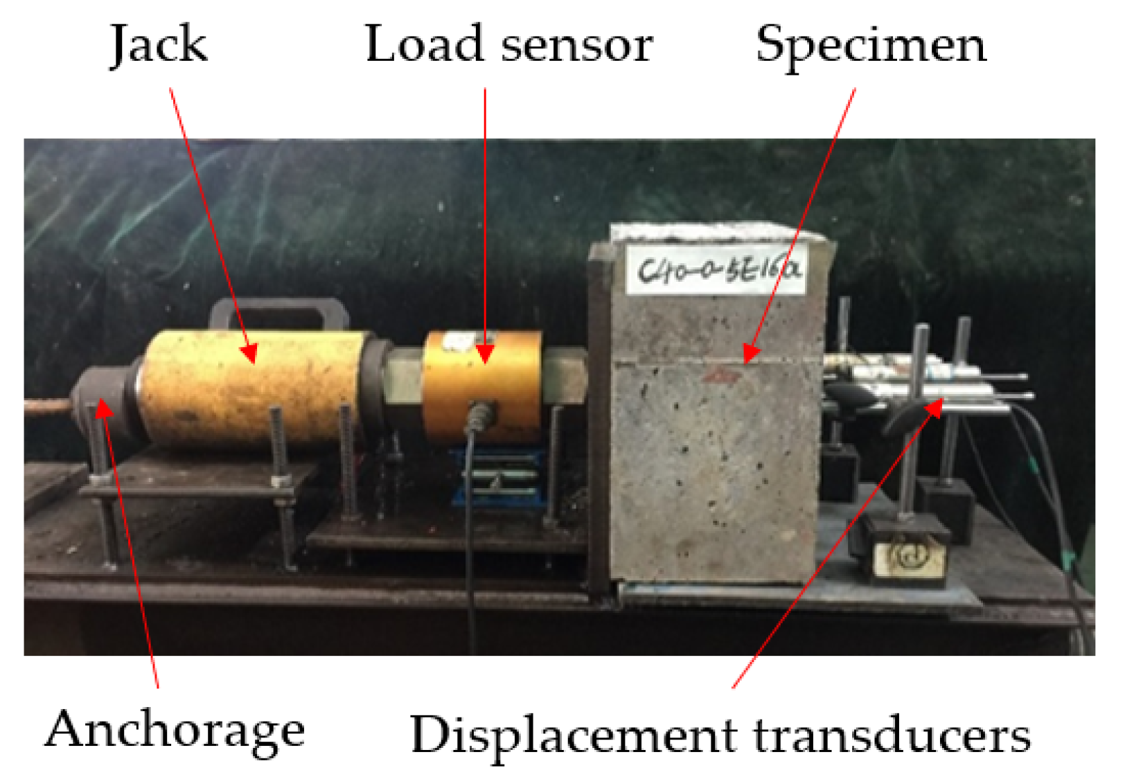
2.3. Pull-Out Test Method

The bond properties of ribbed steel bar embedded in SFRELC was measured by the pull-out test as per China Code GB/T 50152 [32]. As exhibited in Figure 3, the pull-out load was exerted by a hydraulic jack through the load sensor on surface of the test block. The jack and load sensor were placed along the center of steel bar embedded in the SFRELC block on a supporting table. An anchorage was used to fix the end of steel bar on jack. This provides a simple loading state without other influences. According to the China code GB50152-2012, the loading rate was kept in about the value of 0.03d2 N/s, where d is the diameter of steel bar.
Three displacement transducers were placed on the block surface opposite to the test jack, one pointed to the free end of the steel bar and the other two pointed to the concrete surface. The relative displacement between them was the bond slip. The average bond stress (τ) was calculated by the following equation, and the maximum value was the bond strength (τu),
τ = F / ( 5 π d 2 )
where, F is the pull-out load (N), d is the diameter of steel bar (mm).

3. Test Results and Analysis
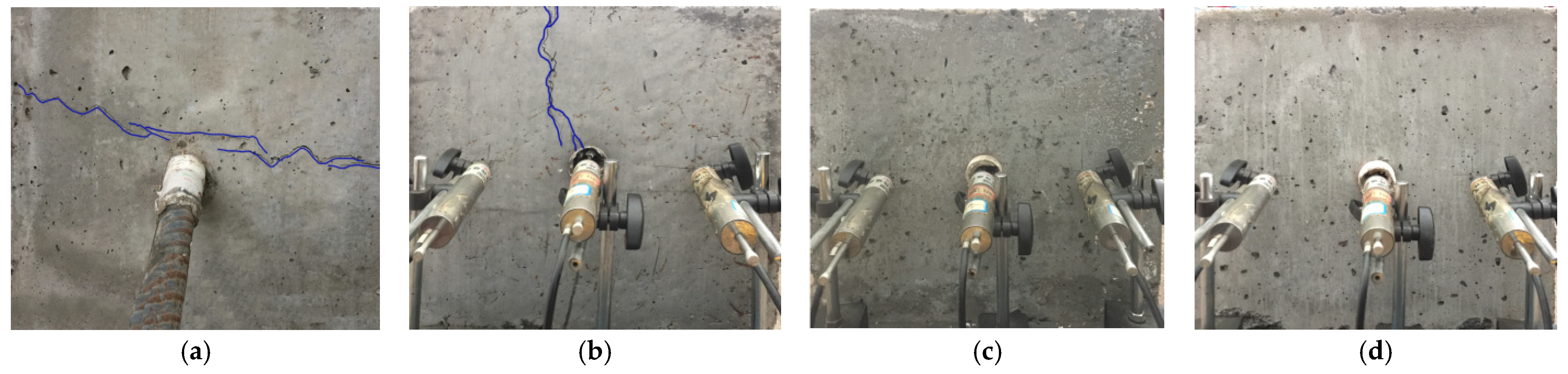
3.1. Failure Mode

The failure modes of specimens with steel bar of diameter d = 28 mm are exhibited in Figure 4. Differing from the block broken into several pieces as reported for the specimens with concrete cover less than 4.5d [4,5,6], cracks only appeared and penetrated on the surface of block without steel fiber. This is because the thickening concrete cover elongated the transfer route of tensile stress and weakened the peak-stress at block surface. Except for the crack that appeared on block with vf = 0.8%, the crack disappeared with the increased volume fraction of steel fiber. This indicates the changes of failure pattern of block due to the strengthening effect of steel fiber on the tensile strength of SFRELC. No sudden collapse occurred on the specimens until the pull-out of the steel bar.
Similar failure modes and smaller cracks appeared on the specimens with steel bar diameter d = 14 mm and 20 mm.

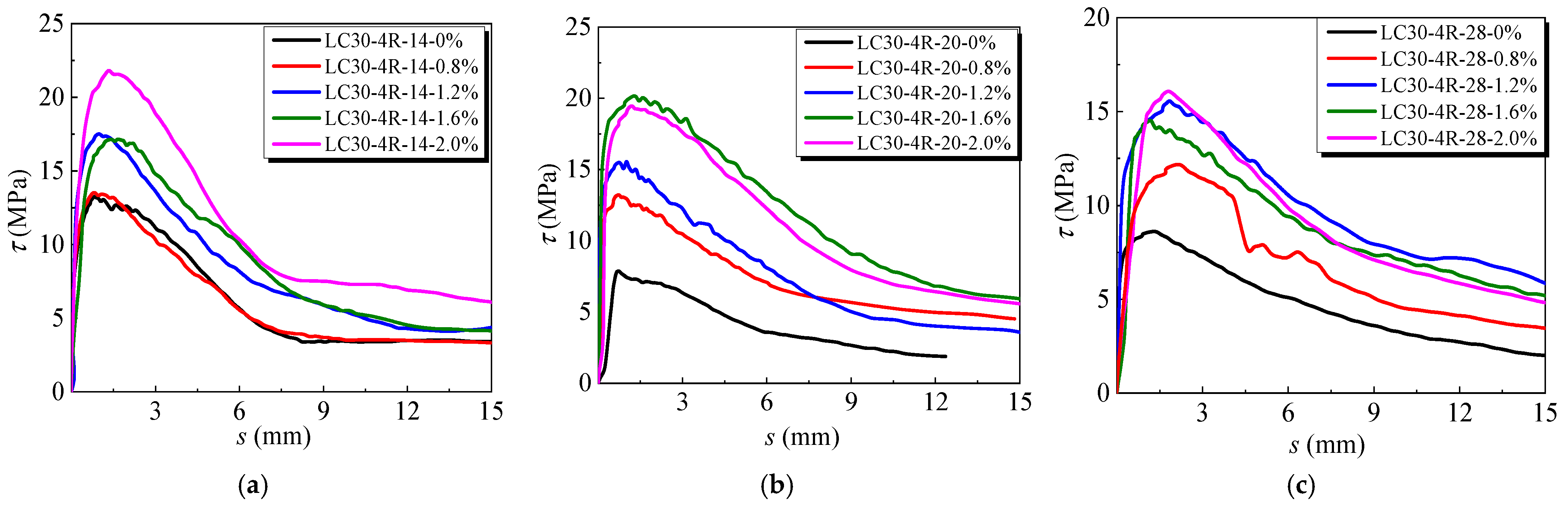
3.2. Bond Stress-Slip Curves

Figure 5 presents the bond stress-slip curves of specimens with different vf. The identifier of test specimens was named as the strength grade of SFRELC–the strength grade of steel bar–the diameter of steel bar–the volume fraction of steel fiber. For instance, LC30-4R-14-0.8% represented that the strength grade of SFRELC was LC30, the strength grade of steel bar was HRB400, which was abbreviated as 4R, the diameter of steel bar was 14 mm, and the volume fraction of steel fiber was 0.8%.
In the elastic ascending stage, bond stress rapidly increased with a micro slip. The slip appeared with the loss of the bond of steel bar to SFRELC. With the increase of the vf, the peak stress increased with the slip, and the bond stress-slip curves near peak-stress presented a change of slop. After the peak-stress, a good descending curve presented with continuous slip vs residual bond stress, due to the prevention of the splitting failure by the strengthening of steel fiber on the tensile strength of SFRELC.
Meanwhile, compared to the bond stress-slip curves of specimens with different diameter of steel bar, the bond strength decreased while the peak-slip increased with the increase of the diameter of steel bar at the same vf. A steeper ascending curve with a shorter nonlinear segment was observed in the specimen with the smaller diameter of steel bar. The slope of descending curves reduced with the increasing diameter of steel bar. The higher bond strength with lower peak-slip and the lowest ability to maintain high residual bond strength was presented on the specimens with steel bar at a diameter of 14mm, and a faster unload rate on the descending curves was presented than those with steel bar at diameter of 20 mm and 28 mm.

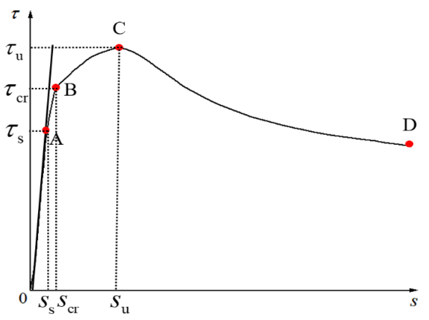
3.3. Bond Stress and Slip at Key Points of Curve

To evaluate the bond behaviors and predict the bond stress-slip curves of pull-out specimen in this study, several key points on the complete curves that were considered and discussed in the following are collected and presented in Table 7. These key points include the slipping bond strength (τs) with micro-slip (ss) at the end of the first linear stage of ascending curve, the splitting bond strength (τcr) with corresponding slip (scr) at the end of the second stage of ascending curve, the bond strength (τu) with peak-slip (su) at the ultimate bond stress point, the residual strength (τr) with corresponding slip (sr) at the last point of inflexion on the curves. They represent the features of bond-slip at different stages of bearing ability.

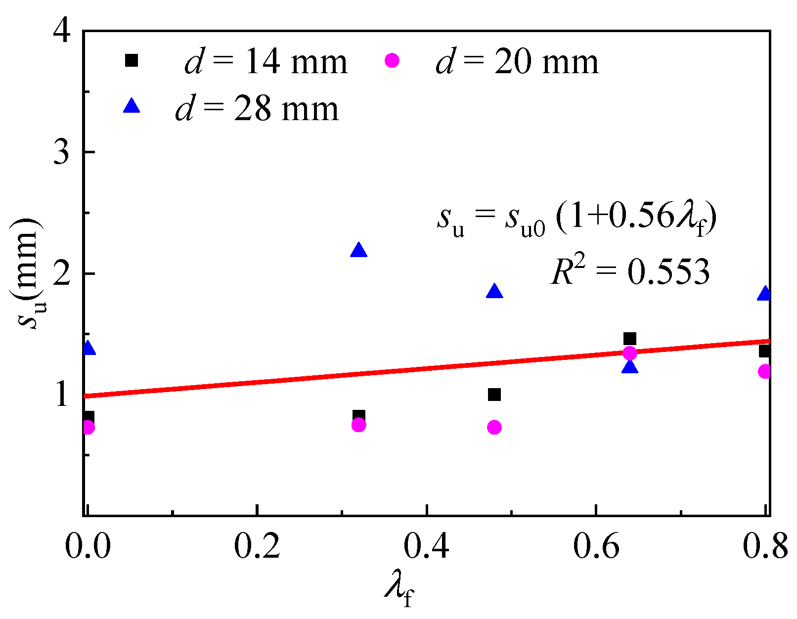
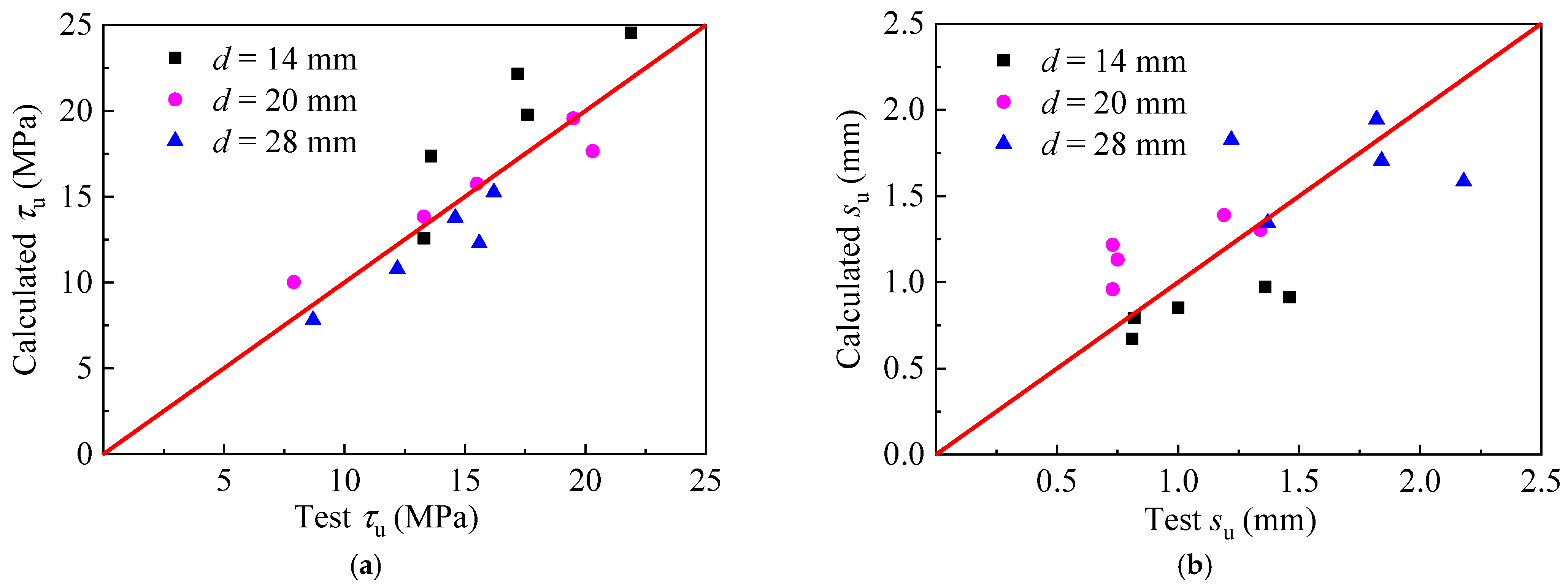
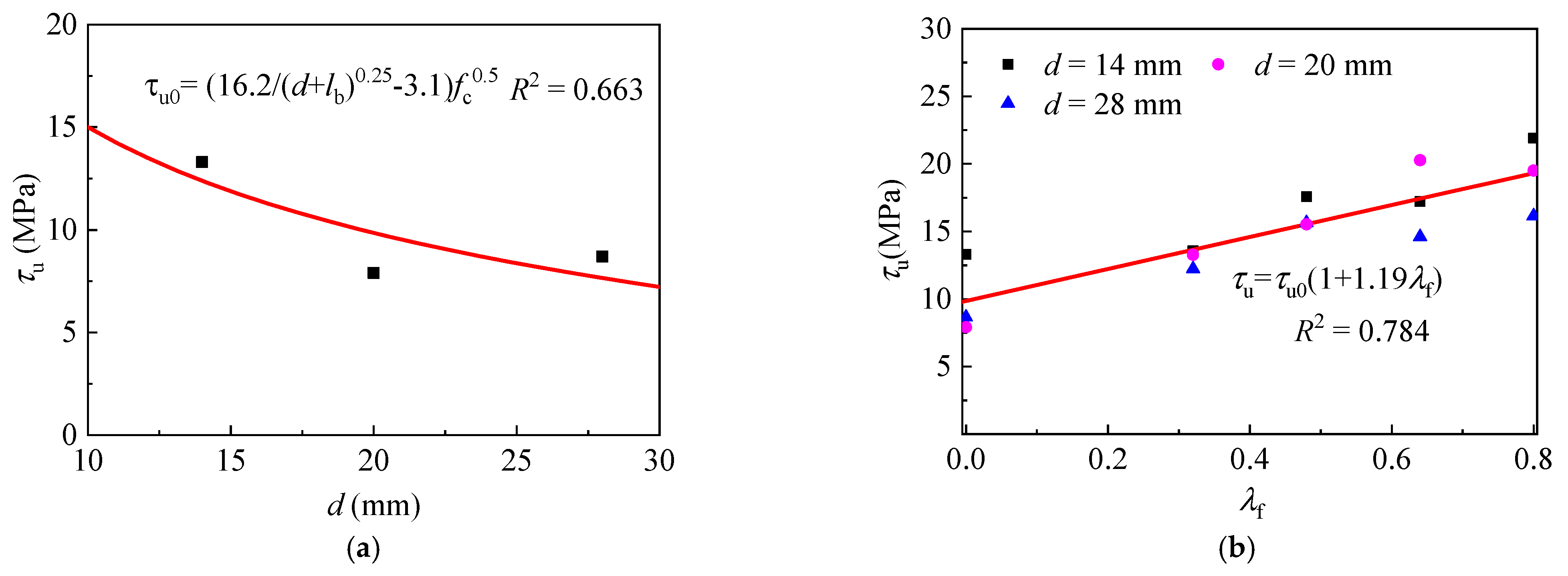
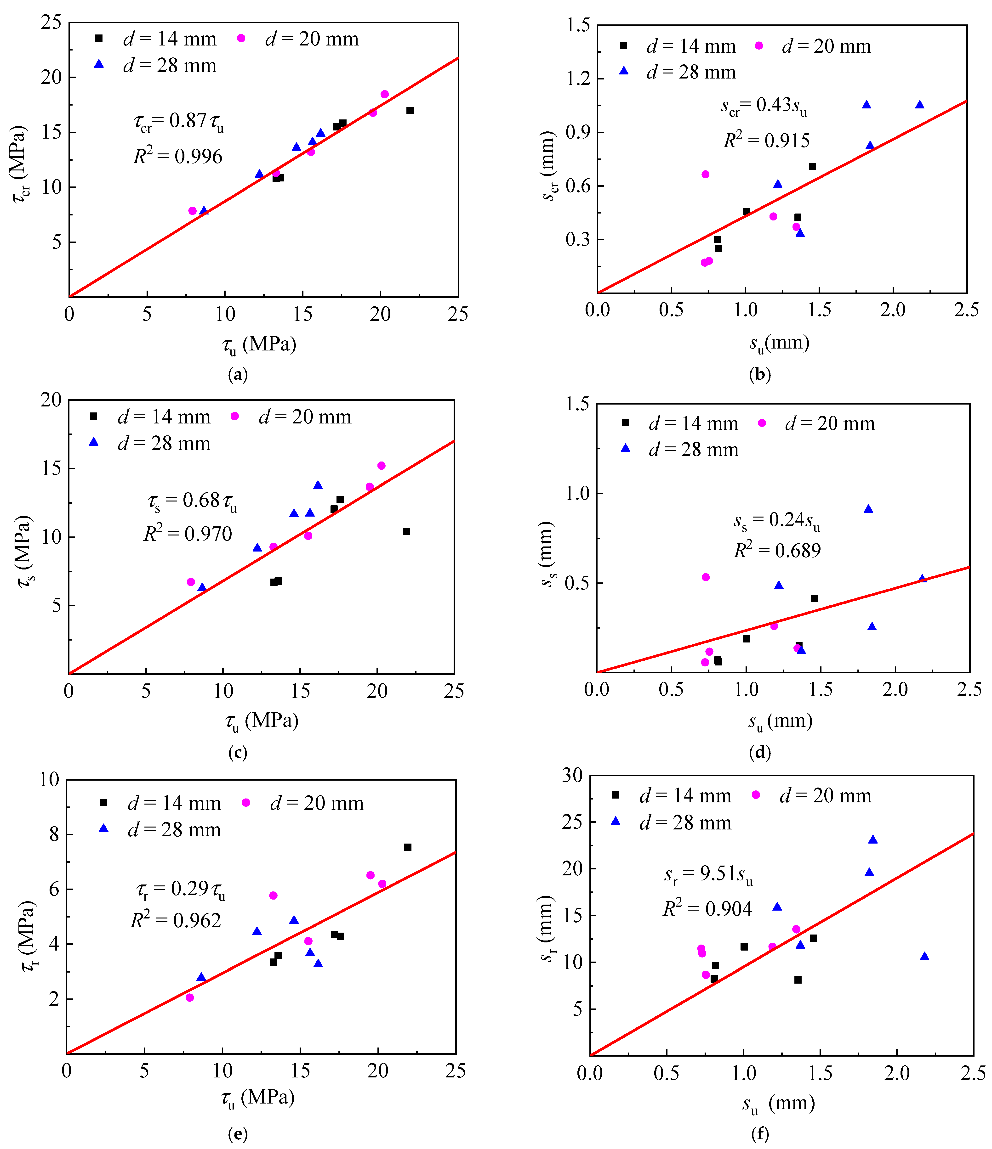
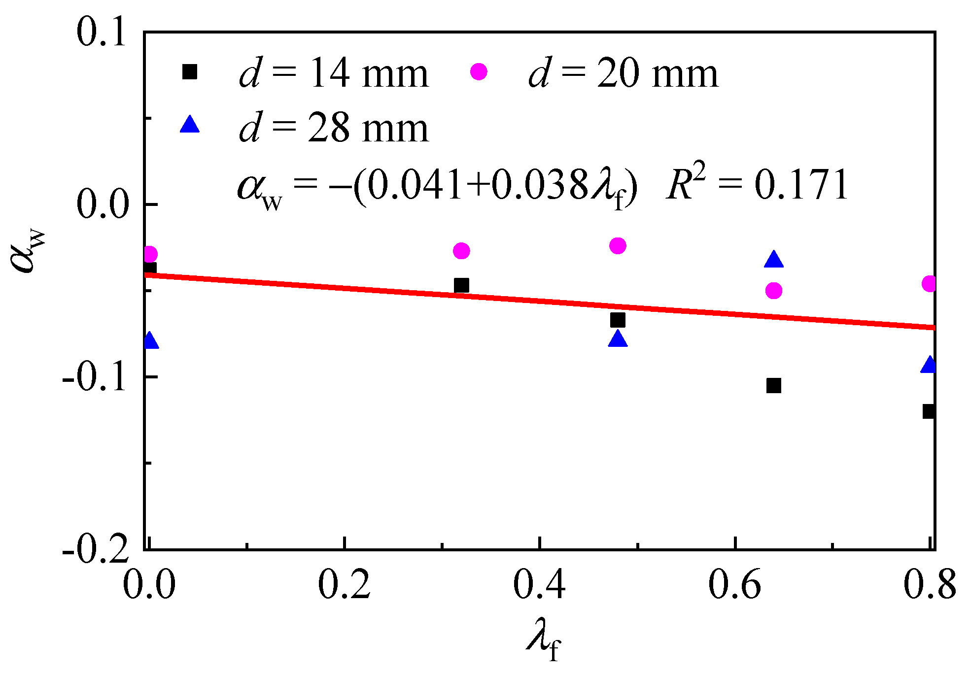
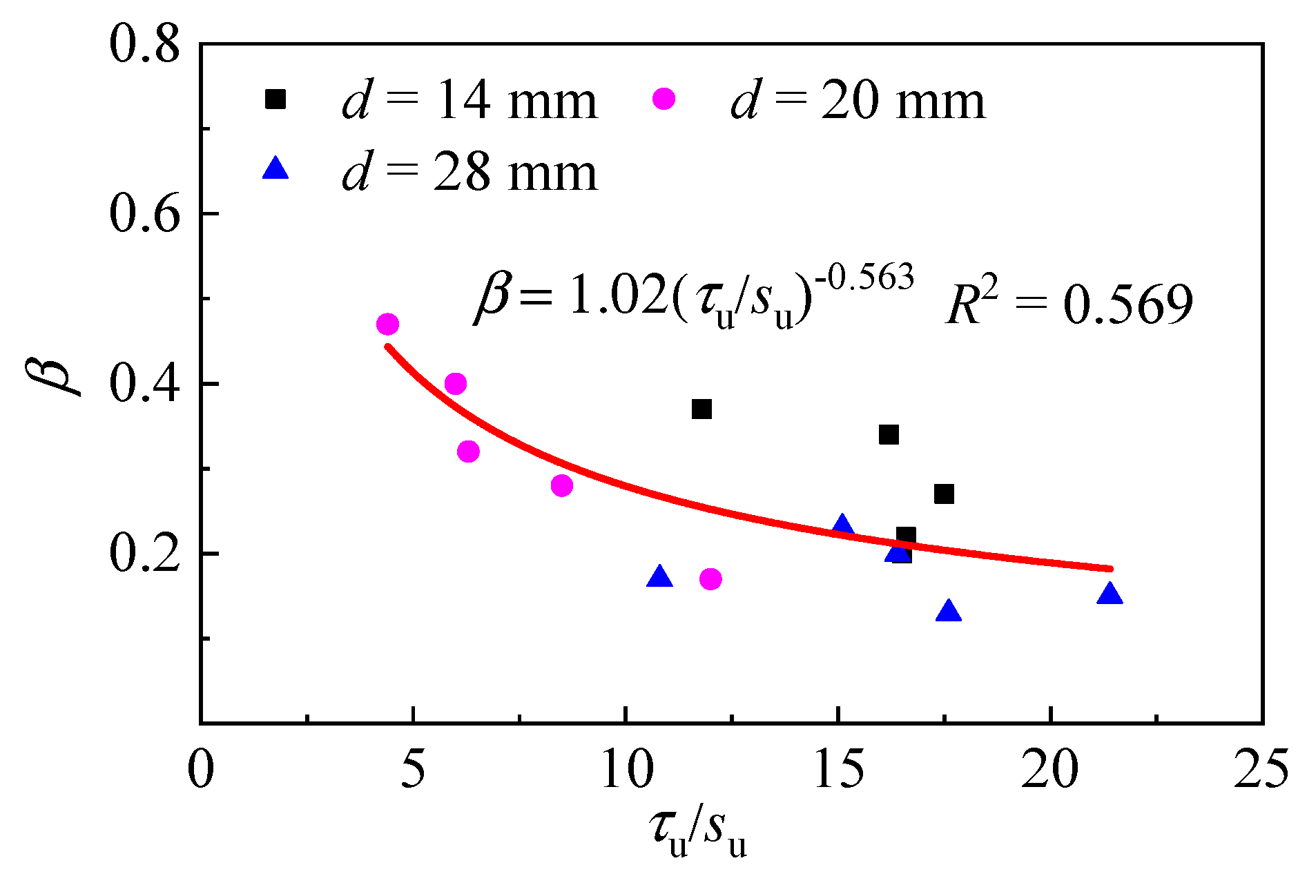
3.4. Prediction of Bond Stress and Slip at Key Points

Bond strengths τu with different diameters of steel bar for specimens without steel fiber are presented in Figure 6a. Formula (2) was obtained for the prediction of bond strength τu0 of specimens without steel fiber by regressing test data with a formula in Kim’s study [33], in which the parameters of diameter d and bond length lb (lb = 5d in this experiment) were taken into account. For the SFRELC specimens, the steel fiber had an enhancement on the bond strength as presented in Figure 6b, and the relationship of τu with the fiber factor λf can be expressed by Formula (3),
τ u 0 = ( 16.2 / ( d + l b ) 0.25 3.1 ) f c 0.5
τ u = τ u 0 ( 1 + 1.19 λ f )
where fc is the axial compressive strength of expanded-shale lightweight concrete (MPa), λf is the fiber factor that comprehensively represents the characteristics of steel fiber, λf = vf·lf/df, vf is the volume fraction of steel fiber, and lf/df is the aspect ratio of steel fiber.
With the test results, peak slip to steel bar diameter ratio (su/d) was about 0.048 for the specimens without steel fiber. The relationship of su and λf is presented in Figure 7, and the formula is written as Formula (4),
s u = 0.048 d ( 1 + 0.56 λ f )
Formula (3) and (4) were used to calculate the bond strength and peak slips for ribbed steel bar in SFRELC in this experiment, and the comparisons of test to calculated results are drawn in Figure 8. The calculated values of the bond strength and the peak-slip close to the test values, while the peak-slip has a little higher dispersion than the bond strength. The average of test to calculated bond strength was 0.994 with a variation coefficient of 0.148. while for peak slips, the average was 1.026 with a variation coefficient of 0.285.
The relationship of bond stresses and slips at key points of complete bond stress-slip curves with the bond strength τu and peak slip su are presented in Figure 9. Based on the regression, τs, τcr, τr were 0.68, 0.87, 0.29 times of τu, while ss, scr, sr were 0.24, 0.43, 9.51 times of su, respectively. On account of the calculation method of these bond strengths and slips on the bond stress-slip curves, complete curves can be predicted by the prediction model in the absence of test data.

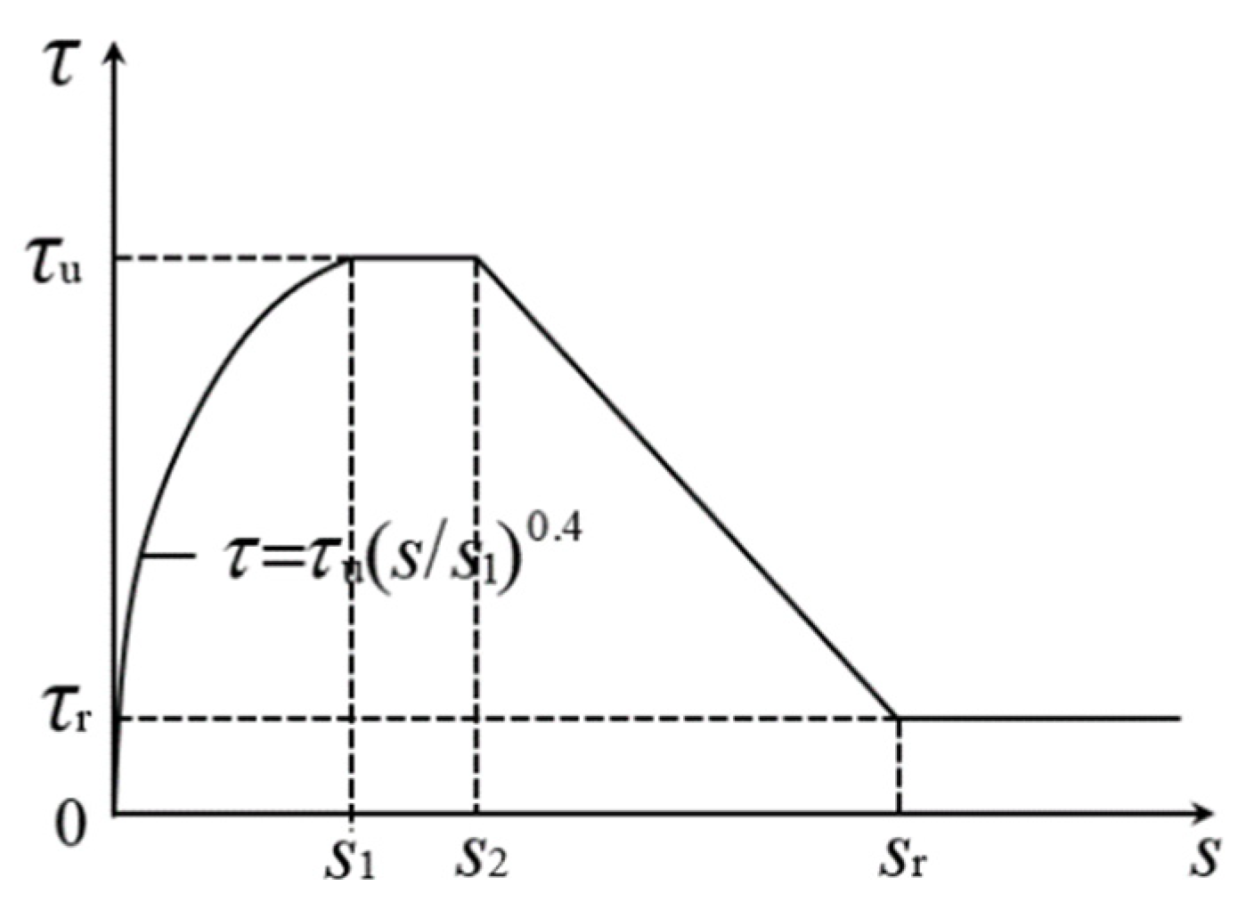
4. Prediction of Bond-Slip Constitutive

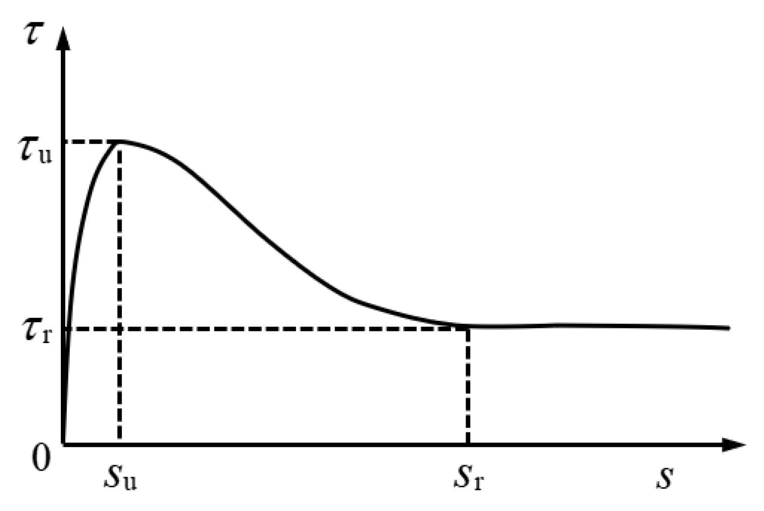
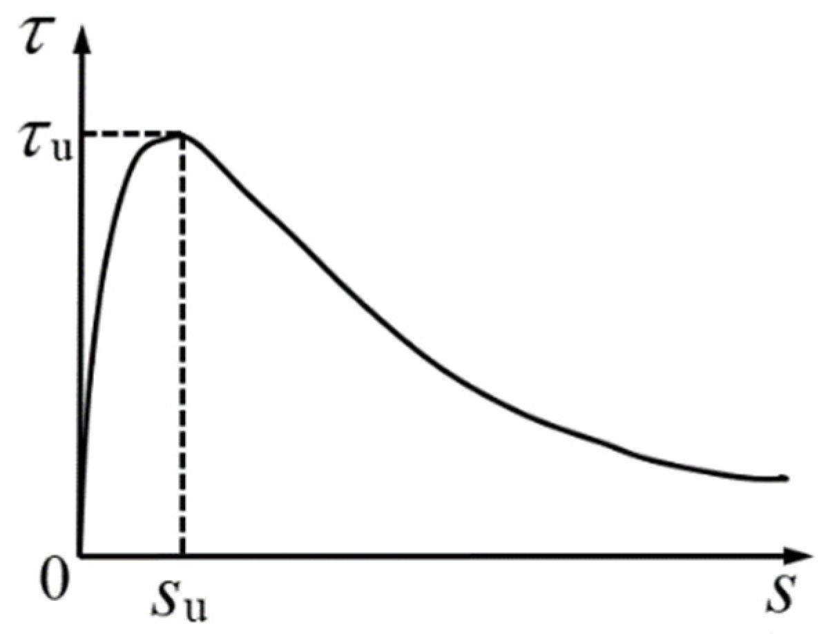
4.1. Constitutive Model

Four prediction models were selected to predict the bond stress-slip relationship of ribbed steel bar in SFRELC. The bond stresses and slips at key points including τs, τcr, τu, τr and ss, scr, su, sr in the prediction models could be calculated as above analyses. Then the predicted bond stress-slip curves were obtained. After comparing the predicted curves with test ones, the proper prediction model was selected.
Model 1:Figure 10 presents the bond stress-slip relationship of steel bar in concrete under monotonic loading which is specified in Fib Model Code 2010 [10]. The bond stress-slip curves composites four segments including ascending, horizontal, descending and residual ones. For the bond stress-slip curves in this experiment, the horizontal segment almost did not exist, and the slips in the second stage s1 = s2 = su. The descending section is approximately expressed by a straight line. The prediction model is presented by formulas,
τ = τ u ( s / s 1 ) 0.4         ( 0 s s 1 )  
τ = τ u             ( s 1 < s s 2 )
τ = τ u ( τ u τ r ) ( s s 2 s r s 2 )     ( s 2 < s s r )
τ = τ r            ( s > s r )
where τ is the bond stress (MPa); s is the relative slip between concrete and ribbed steel bar (mm); s1 and s2 are the slips in the beginning and ending points of horizontal stage (mm); τr is the residual bond stress (MPa); sr is the slip at first point of residual bond stress (mm).
Model 2: The bond stress-slip relationship of steel bar in SFRELC can also be calculated by the least square approach [12,13,14]. The ascending curve of bond stress-slip curve was divided into three segments such as microslip segment (OA), slipping segment (AB) and splitting segment (BC) in Figure 11. Where OA is an approximate elastic segment with a microslip (microslip segment), AB is the section of steel bar slipping without splitting of concrete (slip segment), and BC is the segment of concrete internal splitting in which the cracks have not appeared on the surface of block (internal splitting-broken segment). The descending curve is presented by a nonlinear curve related to the splitting tensile strength of concrete. Details are as shown as follows,
τ = τ s s s s 4               ( 0 s s s )
τ = τ cr ( s 4 s s 4 ) τ s ( s 4 s cr 4 ) s cr 4 s s 4      ( s s < s s cr )
τ = τ u [ 1 ( s s u ) 2 ( s u s cr ) 2 ( 1 τ cr τ u ) ]      ( s cr < s s u )
τ = 0.1 f ts + 1 ( f ts s s u ) 0.34 τ u             ( s u < s d )
where, τs is the slipping bond strength with micro-slip (MPa), ss is the slip related to τs (mm); τcr is the splitting bond strength at internal splitting of concrete (MPa); scr is the slip related to τcr (mm); fts is the tensile strength of SFRELC (MPa).
Model 3: The bond stress-slip curves of ribbed steel bar in self-compacting LAC were proposed by Wu [16]. In this model, the bond stress-slip curve was divided into ascending and descending curves at the bound of peak point presented in Figure 12. With the slips in descending portion reached sr, the ratio of residual bond strength to bond strength τr/τu came infinitely close to a certain value of kr. The calculation model is expressed with the formulas
τ = τ u ( 2 s s u s s u )
τ = τ u ( k r + ( 1 k r ) exp ( α w ( s s u 1 ) 2 ) )
where, kr is the ratio of residual bond strength to bond strength, kr = τr/τu = 0.29; αw is the shape coefficient of descending part of bond stress-slip curves.
The shape coefficient αw can be obtained by the fitness of test curves. As presented in Figure 13, the values of shape coefficient αw decreases with the increase of fiber factor and can be expressed as a linear regression formula. However, the correlation of αw and λf is very low, due to the large variation of the descending portion of curves. This indicates that the shape coefficient αw cannot reflect the effect of steel fiber on the descending portion.
Model 4: Based on fib Model Code 2010 and China Code GB50010-2010, the typical shape of bond stress-slip curves as presented in Figure 14 was proposed by Song et al. [15]. The ascending curve was the same as Formula (5). The descending curve was presented as Formula (15) which is similar to the shape of compressive stress-strain curves of concrete in descending portion.
τ = s / s u β ( s / s u ) 2 + s / s u τ u       ( s > s u )
where, β is the shape coefficient of descending stage of the bond stress-slip curves.
The shape coefficient β can be obtained by the fitness of test curves. As presented in Figure 15, the values of shape coefficient β decreases with the ratio τu/su, and has the exponential relationship of a regression formula.

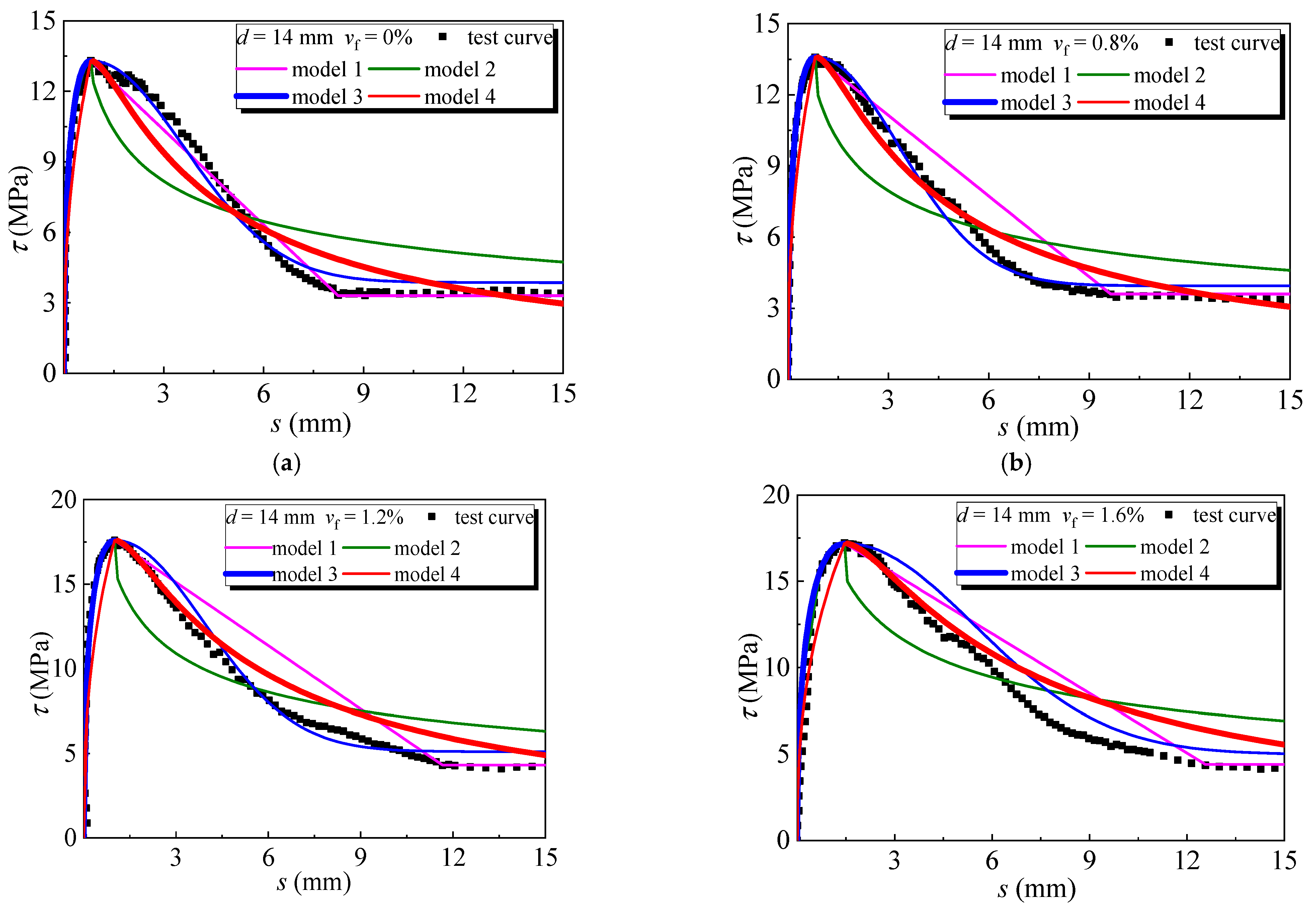
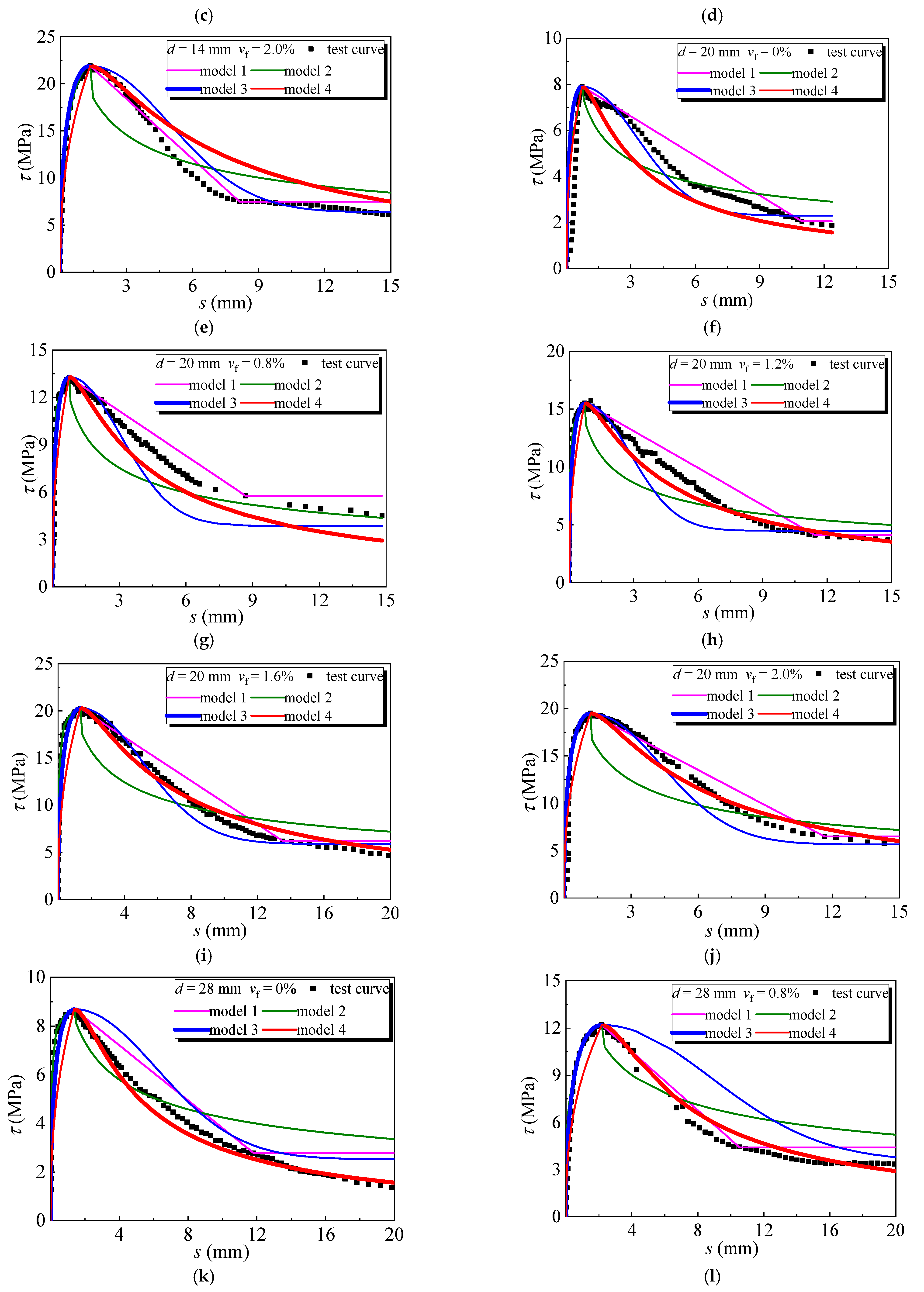
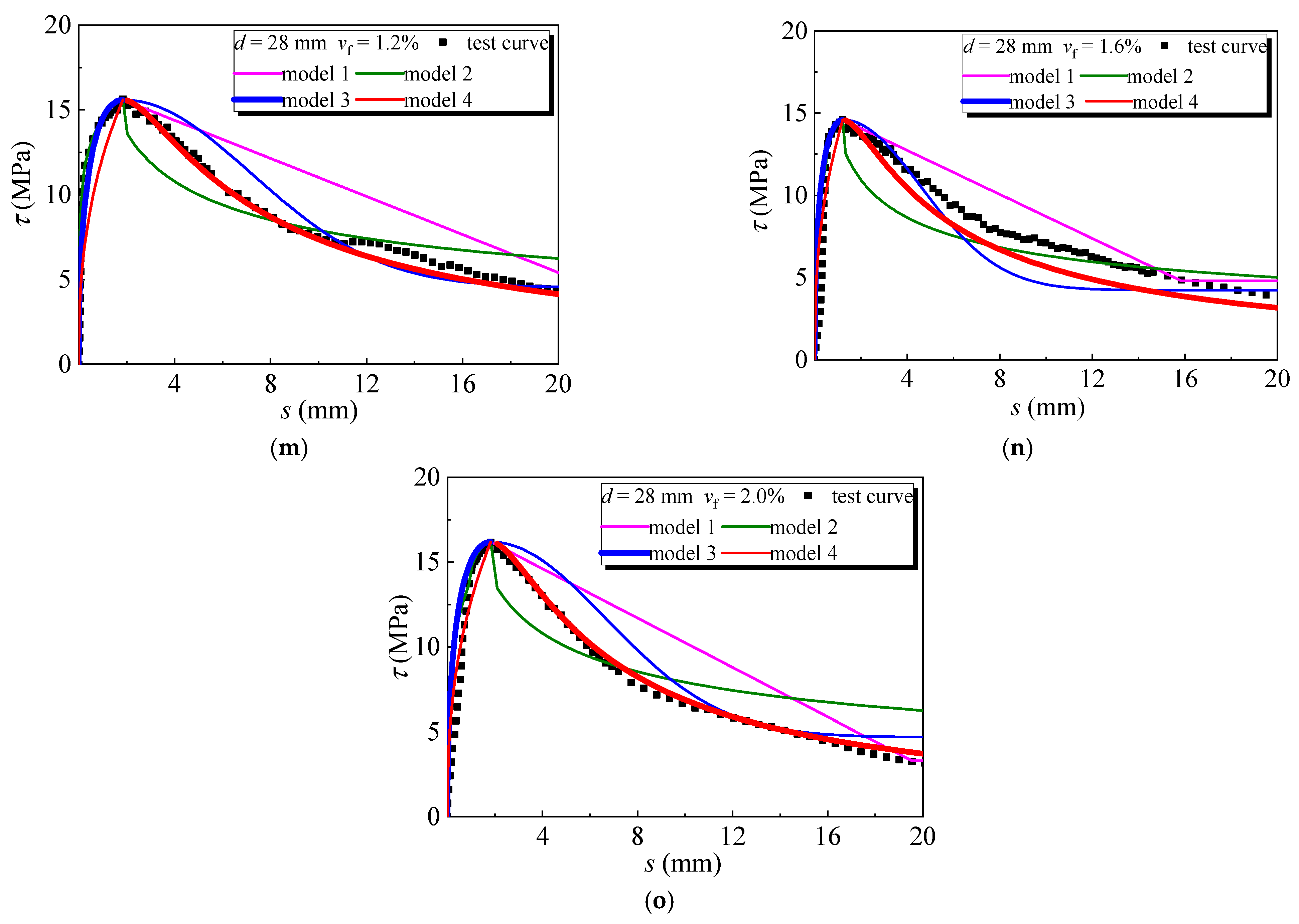
4.2. Comparison with Test Curves

To select the rational prediction model for the bond stress-slip curves of ribbed steel bar in SFRELC, test curves were compared with the calculated ones by the above four models. The comparison of test curves with predicted ones are presented in Figure 16. No obvious difference happens on the ascending portion with the four models, but a main difference appears on the descending portion.
Due to the descending curve expressed as a straight line after the peak stress in Model 1, higher bond stress is predicted with the increasing slip. This gives an unreliable prediction of residual bond strength with slip after peak stress.
A sharp decrease at the initial part with the gradual decline afterward of descending portion appears on the predicted curve of Model 2. The former underrates the bond ability, and the latter overestimates the bond ability. This is irrational to be used for the prediction of bond properties of ribbed steel bar in SFRELC.
Model 3 and Model 4 provide better predictions of the descending portion of the bond stress-slip curve, except for some cases of over or lower estimation of bond stress. The accuracy of predictions was evaluated by the variation coefficient of the test to calculate bond stresses at the same slips. For Model 3, the variation coefficient is 0.107–0.250 for the ascending portion and 0.084–0.325 for the descending portion, except a value of 0.596 for the curve of specimen without steel fiber at d = 28 mm. For Model 4, the variation coefficient was 0.113–0.360 for the ascending portion and 0.050–0.187 for the descending portion. This indicates that the prediction of Model 4 was better on the descending portion, and Model 3 was slightly better on the ascending curves.
Therefore, it is better to predict the complete bond stress-slip curve by using the Formulas (13) and (15), respectively, for the ascending and descending portions.

5. Conclusions

Bond properties of ribbed steel bar embedded in SFRELC were investigated in this experiment. The bond strength and slip, and the bond stress and slip at key points of the complete bond stress-slip curves were obtained, considering the influencing factors of the diameter of steel bar and the volume fraction of steel fiber. Prediction models for bond stress-slip curves were selected. The conclusions were drawn as follows:
(1) Steel fiber benefited prevention of the cracks developed in the SFRELC blocks, and improved the grip of SFRELC on steel bar. When the vf ≤ 0.8%, cracks appeared and extended on the surface of blocks. When the vf ≥ 1.2%, the effect of steel fiber came into play efficiently, and no cracks appeared with the steel bar gradually pulled out;
(2) Bond strength τu increased with the increase of vf, and decreased with the increase of diameter of steel bar. Based on the test results of mechanical properties of SFRELC, calculation formulas for τu and su are proposed. The bond stresses τs, τcr, τr were 0.68, 0.87, 0.29 times of bond strength τu, while their corresponding slips ss, scr, sr are 0.24, 0.43, 9.51 times of peak slip su, respectively;
(3) The descending curves improved with higher residual bond strength by the presence of steel fiber. After the comparison of four prediction models, two models were selected to predict the bond stress-slip curves of ribbed steel bar embedded in SFRELC. The accuracy of prediction of the two models were calculated to give a quantitative evaluation. Finally, a suggestion was proposed to combine the ascending portion of Model 3 and the descending portion of Model 4 for a good prediction of the bond-slip curve for ribbed steel bar in SFRELC;
(4) Due to the bond influenced by multiple factors except for the diameter of steel bar and the volume fraction of steel fiber, much more study should be carried out on the bond performance of steel bar in SFRELC to ensure the reliability of joint work.

Author Contributions

Methodology, Y.Z., G.L. and S.Z.; tests, data interpretation and writing—original draft, M.Z., L.L., K.S. and G.L.; writing—review, and funding acquisition, Y.Z. and S.Z. All authors have read and agreed to the published version of the manuscript.

Funding

This research was funded by Key Scientific Research Project in Universities of Henan, China (grant number 21A560016); Research Fund for High-level Talents of NCWU, China (grant number 202104005), and Innovative Sci-Tech Team of Eco-building Material and Structural Engineering of Henan Province, China (grant number YKRZ-6-066).

Institutional Review Board Statement

Not applicable.

Informed Consent Statement

Not applicable.

Data Availability Statement

The data presented in this study are available on request from the corresponding author.

Conflicts of Interest

The authors declare no conflict of interest.

References

  1. Holschemacher, K.; Ali, A.; Iqbal, S. Bond of reinforcement in lightweight concrete. In Insights and Innovations in Structural Engineering, Mechanics and Computation; Taylor & Francis Group: London, UK, 2016; pp. 1284–1285. [Google Scholar]
  2. Zhang, D.X.; Yang, W.J. Experimental research on bond behaviors between shale ceramsite lightweight aggregate concrete and bars through pullout tests. J. Mater. Civ. Eng. 2014, 27, 06014030. [Google Scholar] [CrossRef]
  3. Lachemi, M.; Bae, S.; Hossain, K.M.A.; Sahmaran, M. Steel-concrete bond strength of lightweight self-consolidating concrete. Mater. Struct. 2009, 42, 1015–1023. [Google Scholar] [CrossRef]
  4. Kaffetzakis, M.I.; Papanicolaou, C.G. Bond behavior of reinforcement in lightweight aggregate self-compacting concrete. Constr. Build. Mater. 2016, 113, 641–652. [Google Scholar] [CrossRef]
  5. Al-Shannag, M.J.; Charif, A. Bond behavior of steel bars embedded in concretes made with natural lightweight aggregates. J. King Saud Univ.-Eng. Sci. 2017, 29, 365–372. [Google Scholar] [CrossRef]
  6. Mo, K.H.; Alengaram, U.J.; Visintin, P.; Goh, S.H.; Jumaat, M.Z. Influence of lightweight aggregate on the bond properties of concrete with various strength grades. Constr. Build. Mater. 2015, 84, 377–386. [Google Scholar] [CrossRef] [Green Version]
  7. Zhao, M.S.; Zhang, X.Y.; Yan, K.; Fei, T.; Zhao, S.B. Bond performance of ribbed rebar in steel fiber reinforced lightweight-aggregate concrete affected by multi-factors. Civ. Eng. J. 2018, 23, 276–290. [Google Scholar]
  8. Bogas, J.A.; Gomes, M.G.; Real, S. Bonding of steel reinforcement in structural expanded clay lightweight aggregate concrete: The influence of failure mechanism and concrete composition. Constr. Build. Mater. 2014, 65, 350–359. [Google Scholar] [CrossRef]
  9. Mo, K.H.; Alengaram, U.J.; Jumaat, M.Z. Bond properties of lightweight concrete—A review. Constr. Build. Mater. 2016, 112, 478–496. [Google Scholar] [CrossRef]
  10. Fib Special Activity Group 5. Fib Model Code for Concrete Structures 2010; Case Postale 88, CH-1015; International Federation for Structural Concrete (Fib): Lausanne, Switzerland, 2013. [Google Scholar]
  11. Ministry of Housing and Urban-Rural Construction of the People’s Republic of China. Code for Design of Concrete Structures; GB50010-2010; China Building Industry Press: Beijing, China, 2010. [Google Scholar]
  12. Li, C.Y.; Zhao, M.L.; Ren, F.C.; Liang, N.; Li, J.; Zhao, M.S. Bond behaviors between full-recycled-aggregate concrete and ribbed steel-bar. Open Civ. Eng. J. 2017, 11, 685–698. [Google Scholar] [CrossRef] [Green Version]
  13. Xu, Y.L.; Shen, W.D.; Wang, H. An experimental study on bond-anchorage properties of bars in concrete. J. Build. Struct. 1994, 15, 26–37. [Google Scholar]
  14. Zhao, S.B.; Ding, X.X.; Li, C.M.; Li, C.Y. Experimental study of bond properties between ribbed steel bar and concrete with machine-made sand. J. Build. Mater. 2013, 16, 191–202. [Google Scholar] [CrossRef]
  15. Song, L.; Qu, F.L.; Liu, G.R.; Zhao, S.B. Bond properties of steel bar in concrete under water environment. Materials 2019, 12, 3517. [Google Scholar] [CrossRef] [Green Version]
  16. Wu, X. Mechanical Properties of Self-Compacting Lightweight Concrete. Ph.D. Thesis, Dalian University of Technology, Dalian, China, 2013. [Google Scholar]
  17. Güneyisi, E.; Gesoğlu, M.; Ipek, S. Effect of steel fiber addition and aspect ratio on bond strength of cold-bonded fly ash lightweight aggregate concretes. Constr. Build. Mater. 2013, 47, 358–365. [Google Scholar] [CrossRef]
  18. Ali, A.; Iqbal, S.; Holschemacher, K.; Bier, A.T. Effect of fibers on bond performance of lightweight reinforced concrete. Period. Polytech. Civ. Eng. 2016, 60, 97–102. [Google Scholar] [CrossRef] [Green Version]
  19. Mo, K.H.; Goh, S.H.; Alengaram, U.J.; Visintin, P.; Jumaat, M.Z. Mechanical, toughness, bond and durability-related properties of lightweight concrete reinforced with steel fibers. Mater. Struct. 2017, 50, 46. [Google Scholar] [CrossRef]
  20. Li, F.L.; Yu, Y.N.; Yu, K.F.; Chen, J.Q. Experimental study on bond properties of plain steel-bar with SFRLAC. J. Hebei Univer. Technol. 2014, 43, 93–96. [Google Scholar]
  21. Zhao, M.L.; Zhao, M.S.; Chen, M.H.; Li, J.; Law, D. An experimental study on strength and toughness of steel fiber reinforced expanded-shale lightweight concrete. Constr. Build. Mater. 2018, 183, 493–501. [Google Scholar] [CrossRef]
  22. Li, C.Y.; Zhao, M.L.; Geng, H.B.; Fu, H.; Zhang, X.Y.; Li, X.K. Shear performance of steel fiber reinforced expanded-shale lightweight concrete beams with varying of shear-span to depth ratio and stirrups. Case Study Constr. Mater. 2021, 14, e00550. [Google Scholar]
  23. Li, C.Y.; Zhao, M.S.; Yang, J.L.; Xu, W.X.; Zhang, X.Y. Shear testing of reinforced hybrid composite beams made of SFRELC and partial higher-strength conventional concrete. Case Study Constr. Mater. 2021, 15, e00721. [Google Scholar] [CrossRef]
  24. General Administration of Quality Supervision of the People’s Republic of China. Metallic Materials-Tensile Testing—Part 1: Method of Test at Room Temperature; GB/T 228-2010; China Standard Press: Beijing, China, 2010. [Google Scholar]
  25. Ministry of Housing and Urban-Rural Construction of the People’s Republic of China. Lightweight Aggregate and Its Test Methods—Part 2: Test Methods for Lightweight Aggregates; GB/T 17431.2-2010; China Building Industry Press: Beijing, China, 2010. [Google Scholar]
  26. Ministry of Housing and Urban-Rural Construction of the People’s Republic of China. Technical Standard for Application of Lightweight Aggregate Concrete; JGJ/T12-2019; China Building Industry Press: Beijing, China, 2019. [Google Scholar]
  27. Ding, X.X.; Zhao, M.L.; Li, J.; Shang, P.R.; Li, C.Y. Mix proportion design of self-compacting SFRC with manufactured sand based on the packing test of steel fiber-aggregates skeleton. Materials 2020, 13, 2833. [Google Scholar] [CrossRef]
  28. Ministry of Housing and Urban-Rural Construction of the People’s Republic of China. Standard for Test Method of Performance on Ordinary Fresh Concrete; GB/T50080-2016; China Building Industry Press: Beijing, China, 2016. [Google Scholar]
  29. Zhao, S.B.; Zhao, M.S.; Zhang, X.Y.; Peng, Z.J.; Huang, T.H. Study on complete stress-strain curves of steel fiber reinforced lightweight-aggregate concrete under uniaxial compression. J. Build. Struct. 2019, 40, 181–190. [Google Scholar]
  30. Zhao, M.S.; Zhang, B.X.; Shang, P.R.; Fu, Y.; Zhang, X.Y.; Zhao, S.B. Complete stress–strain curves of self-compacting steel fiber reinforced expanded-shale lightweight concrete under uniaxial compression. Materials 2019, 12, 2979. [Google Scholar] [CrossRef] [PubMed] [Green Version]
  31. Ministry of Housing and Urban-Rural Construction of the People’s Republic of China. Steel Fiber Reinforced Concrete; JG/T 472-2015; China Building Industry Press: Beijing, China, 2015. [Google Scholar]
  32. General Administration of Quality Supervision of the People’s Republic of China. Standard for Test Method of Concrete Structures; GB/T 50152-2012; China Standard Press: Beijing, China, 2012. [Google Scholar]
  33. Kim, D.; Kim, M.S.; Yun, G.Y.; Lee, Y.H. Bond strength of steel ribbed rebars embedded in artificial lightweight aggregate concrete. J. Adhesion Sci. Technol. 2013, 27, 490–507. [Google Scholar] [CrossRef]
Figure 1. Specimen of bond-slip by using the direct pull-out test.
Buildings 11 00582 g001
Figure 2. The HRB400 hot-rolled ribbed steel bar.
Buildings 11 00582 g002
Figure 3. Device for central pull-out test.
Buildings 11 00582 g003
Figure 4. Failure modes of tested specimens: (a) vf = 0%; (b) vf = 0.8%; (c) vf = 1.2%; (d) vf = 1.6%.
Buildings 11 00582 g004
Figure 5. Bond stress-slip curves of specimens with different vf at: (a) d = 14 mm; (b) d = 20 mm; (c) d = 28 mm.
Buildings 11 00582 g005
Figure 6. Changes of τu with factor: (a) d; (b) λf.
Buildings 11 00582 g006
Figure 7. Relationship of su and λf.
Buildings 11 00582 g007
Figure 8. Comparison of test and calculated results: (a) bond strength τu; (b) slip su.
Buildings 11 00582 g008
Figure 9. Relationships of bond stress and slip at key points with bond strength τu and peak-slip su: (a) τcr; (b) scr; (c) τs; (d) ss; (e) τr; (f) sr.
Buildings 11 00582 g009
Figure 10. Bond stress-slip curve in Fib Model Code 2010.
Buildings 11 00582 g010
Figure 11. Bond stress-slip curve of Model 2.
Buildings 11 00582 g011
Figure 12. Bond stress-slip curve of Model 3.
Buildings 11 00582 g012
Figure 13. Change of shape coefficient αw with fiber factor.
Buildings 11 00582 g013
Figure 14. Bond stress-slip curve of Model 4.
Buildings 11 00582 g014
Figure 15. Change of shape coefficient β with τu/su.
Buildings 11 00582 g015
Figure 16. Comparison for bond stress-slip curves with calculation models: d = 14 mm, (a) vf = 0%, (b) vf = 0.8%, (c) vf = 1.2%, (d) vf = 1.6%, (e) vf = 2.0%; d = 20 mm, (f) vf = 0%, (g) vf = 0.8%, (h) vf = 1.2%, (i) vf = 1.6%, (j) vf = 2.0%; d = 28 mm, (k) vf = 0%, (l) vf = 0.8%, (m) vf = 1.2%, (n) vf = 1.6%, (o) vf = 2.0%.
Buildings 11 00582 g016aBuildings 11 00582 g016bBuildings 11 00582 g016c
Table 1. Test results of outline dimension and mechanical properties of ribbed steel bars.
GradeDiameter
d (mm)
Transverse Rib (mm)Longitudinal Rib (mm)Yield Strength
fy (MPa)
Ultimate Tensile Strength fst (MPa)Elongation After Fracture δ (%)
HeightWidthHeightWidth
HRB400141.40.81.81.845362922.7
201.71.22.12.047363020.4
282.21.72.73.049665618.4
Table 2. Physical and mechanical properties of cement.
Water Requirement of Normal Consistency (%)Setting Time (min)Compressive Strength (MPa)Tensile Strength (MPa)
InitialFinal3d28d3d28d
28.514222926.149.44.978.64
Table 3. Physical properties of fly-ash.
Density (kg/m3)Specific Surface (m2/kg)Water Demand Ratio (%)Moisture Content (%)Ignition Loss (%)
2342406840.12.6
Table 4. Physical and mechanical properties of expanded-shale and ceramsite sand.
AggregatesParticle Size (mm)Fineness ModulusApparent
Density (kg/m3)
Bulk Density (kg/m3)Compacting Density (kg/m3)1 h Water Absorption (%)Cylinder
Compressive Strength (MPa)
Sand0–23.2185110688.48
expanded-shale2–1616538969326.047.1
Table 5. Mix proportion of high-performance SFRELC.
TrialsDosage of Raw Materials (kg/m3)
CementFly AshExpanded—ShaleCeramsite SandWaterAdditional WaterSuperplasticizerSteel Fiber
LC30-0496124538473192732.7
LC30-0.8496124525473192723.262.8
LC30-1.2496124518473192713.594.2
LC30-1.6496124511473192713.7125.6
LC30-2.0496124505473192713.7157
Table 6. Test results of slump, mechanical properties and apparent dry density of SFRELC.
TrialsSlump (mm)fcu (MPa)fc (MPa)Ec (GPa)fst (MPa)ρd (kg/m3)
LC30-020838.231.219.51.871622
LC30-0.817341.231.819.12.661716
LC30-1.216543.633.819.22.851732
LC30-1.69445.437.818.03.251767
LC30-2.06255.143.117.04.191800
Table 7. Test results of bond strength and peak slip.
Trialsfc (MPa)fst (MPa)d
(mm)
vf
(%)
τs (MPa)ss (mm)τcr (MPa)scr (mm)τu (MPa)su (mm)τr (MPa)sr (mm)
LC30-4R-14-0%31.21.871406.70.0710.80.3013.30.813.38.24
LC30-4R-14-0.8%31.82.66140.86.80.0610.90.2513.60.823.69.64
LC30-4R-14-1.2%33.82.85141.212.80.1915.80.4617.61.004.311.66
LC30-4R-14-1.6%37.83.25141.612.00.4115.50.7117.21.464.412.57
LC30-4R-14-2.0%43.14.19142.010.40.1517.00.4221.91.367.58.13
LC30-4R-20-0%31.21.872006.70.537.80.667.90.732.110.97
LC30-4R-20-0.8%31.82.66200.89.30.1211.30.1813.30.755.88.67
LC30-4R-20-1.2%33.82.85201.210.10.0613.20.1715.50.734.111.44
LC30-4R-20-1.6%37.83.25201.615.20.1418.50.3720.31.346.213.53
LC30-4R-20-2.0%43.14.19202.013.70.2616.80.4319.51.196.511.65
LC30-4R-28-0%31.21.872806.30.127.80.338.71.372.811.78
LC30-4R-28-0.8%31.82.66280.89.20.5211.11.0512.22.184.410.53
LC30-4R-28-1.2%33.82.85281.211.70.2514.10.8215.61.843.723.04
LC30-4R-28-1.6%37.83.25281.611.70.4813.60.6114.61.224.815.85
LC30-4R-28-2.0%43.14.19282.013.70.9114.91.0516.21.823.319.55
Publisher’s Note: MDPI stays neutral with regard to jurisdictional claims in published maps and institutional affiliations.

