Article

Moisture Accumulation in Building Façades Exposed to Accelerated Artificial Climatic Ageing—A Complementary Analysis to NT Build 495

1
Department of Civil and Environmental Engineering, Norwegian University of Science and Technology, NO 7491 Trondheim, Norway
2
SINTEF Community, Department of Architecture, Materials and Structures, NO 7465 Trondheim, Norway
*
Author to whom correspondence should be addressed.
Buildings 2021, 11(12), 568; https://doi.org/10.3390/buildings11120568
Submission received: 19 October 2021 / Revised: 17 November 2021 / Accepted: 18 November 2021 / Published: 23 November 2021
(This article belongs to the Special Issue Assessment, Diagnosis and Service Life Prediction)

Abstract

:
Building façades must endure severe climatic exposure throughout their lifetimes. To prevent damage and expensive repairs, ageing tests are used in durability assessments. The NT Build 495 describes an artificial ageing procedure to address building material and component resistance to ultraviolet (UV) light, heat, water, and frost using a climate simulator. The test has been used for decades to investigate exterior surface materials and façade products but has only recently been adopted for multi-layered systems. This study investigates moisture accumulation in a façade system for retrofitting based on concrete and thermal insulation. Hygrothermal simulations of the façade system subjected to ageing were conducted. Moisture accumulation was considered theoretically for the current test procedure and compared to a modified setup in which the interior climate was controlled at 21 °C. Physical measurements were performed in the climate simulator to determine the boundary conditions. Results showed that moisture accumulation in the thermal insulation was largely affected by the type of concrete, that applying a water-repellent surface treatment reduced moisture accumulation, and that the current setup resulted in less moisture accumulation compared to the modified setup. The latter implicates accelerated degradation with the modified setup.

1. Introduction

Buildings are exposed to severe degrading factors throughout their lifetime, including solar radiation, high temperatures, wind-driven rain, freeze–thaw, and chemical substances [1]. More intense rainfall events and increased annual precipitation are predicted in many geographical regions with cold climates owing to climate change [2]. When a building’s “weather skin” fails to withstand climatic exposures over time, failures/leaks occur. Moisture penetrating the building envelope can lead to a range of damages, influence occupants’ health and comfort, incur extensive costs, and reduce the thermal performance of the envelope [3,4,5,6]. As damage can be prevented by selecting durable materials and façade systems, accelerated ageing tests have emerged as an important tool to promote sustainable buildings [7].
Accelerated artificial ageing involves subjecting materials to climatic factors similar to those experienced through a building’s service life, but at a high intensity over a shorter period. In this way, the vulnerability of building products or façade systems can be tested within a reasonable time. Many different types of climate ageing laboratory apparatuses have been developed for this purpose [1], including the climate simulator described by Nordtest NT Build 495 [8]. The method is intended to expose the materials and components used in a building envelope to ultraviolet (UV) light, heat, water, and frost. During the accelerated artificial climatic ageing test NT Build 495, the specimens are positioned vertically in a rotating carousel and exposed to the four degrading factors repeatedly for one hour each (see Section 2.2). The method does not include resistance to mechanical loads such as hail, which might be an issue for Exterior Thermal Insulation Composite Systems (ETICS) [9]. Other relevant degrading factors omitted from the test are environmental pollution and dirt deposition, mould growth, vibrations, and wind [3].
The SINTEF, as the leading test facility in Norway, has used the NT Build 495 climate simulator as a standardised exposure method for building materials and components for several decades. Comparing test results to experiences from field investigations has contributed to substantiating the applicability of the test method [1,6]. The test is primarily used to consider whether materials and components can withstand climatic exposures as harsh as those they may be subjected to in real life; if the exposure in the simulator is endured, the durability is likely to be sufficient. Improvements are called for if damage occurs after a short exposure time. Through repetitive testing, improvements to the material composition or component design can be investigated and compared with the initial results. Wind barriers, wood shingles and façade claddings, underlayer roofs, tape for building purposes, brick, sealings, windows, and renders are examples of façade materials which through testing according to NT Build 495 have achieved a documented level of durability [10,11,12,13]. The test is also applied to façade systems such as ETICS because the outer surface is vulnerable to cracking owing to freeze–thaw [6] and elevated temperatures caused by solar radiation [14]. When exposed to severe driving-rain conditions, assemblies with only a single-stage protection against wind and rain are particularly vulnerable, as cracking of the exterior surface leads to leaks. Owing to the limited drying ability, even small cracks can cause moisture to accumulate in the underlying structure and lead to damage [6].
Rainwater may also be transferred into the underlying structure by capillary conduction or diffusion; the latter may occur when the exterior surface is wetted by rain and subsequently heated by solar radiation. The uptake of rainwater at the surface depends mainly on the capillary properties of the exterior materials, and whether a water-repellent surface treatment is applied. The impact of these transfer mechanisms on the overall moisture performance of assemblies varies depending on the mass transfer properties which are often lacking, time-consuming, or expensive to measure, and may show large standard deviations for the same material [15]. Numerical simulations are commonly used to investigate the drying ability of assemblies; however, results are often prone to large deviations because of large uncertainties in the mass transfer properties and the inability to realistically include the diffusion and suction contacts between material layers [15].
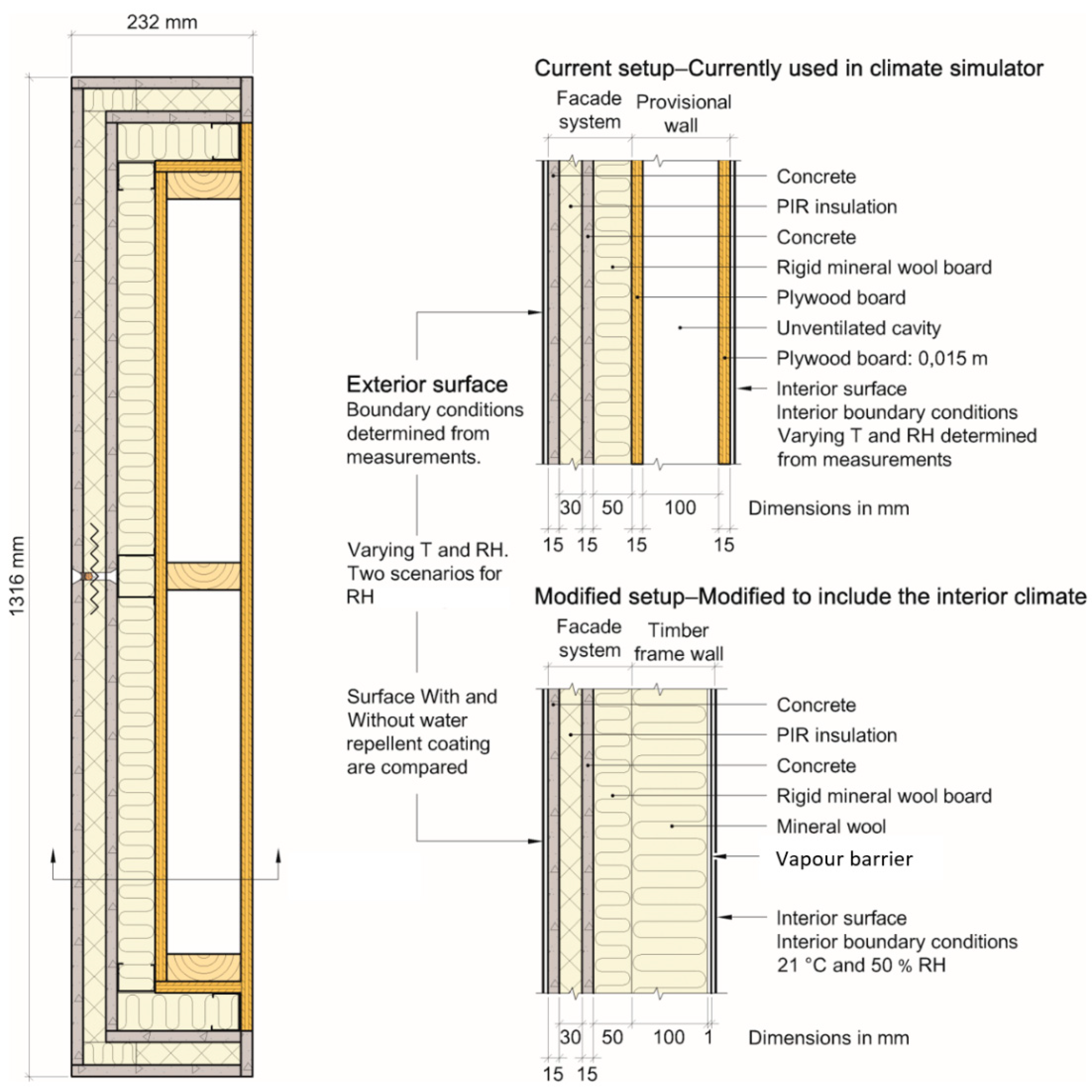
In Norway, Technical Approvals authorized by SINTEF Certification, document to builders that a façade system is suitable for the Norwegian climate. The criteria to obtain a Technical Approval are mainly based on methods and criteria for assessing the performance given by EAD 040083-00-0404 [16], but testing of durability properties according to NT Build 495 is additionally required. The NT Build 495 has been found to be an applicable test method in Norway [6]; however, the test is currently carried out without a habitable climate on the indoor side of the specimen. Façade systems are subjected to degrading climatic factors on the exterior side and the temperature/relative humidity (RH) on the interior side is currently not controlled; that is, the temperature/RH on the interior side follows the fluctuations on the exterior side. Although this practice works adequately in most cases, it is necessary to investigate whether the interior climate should be controlled when moisture-sensitive assemblies are assessed—e.g., assemblies with only single-stage protection against rain intrusion.
In the authors’ opinion, omitting to control the interior climate (as in the current test setup) should not result in more moisture accumulation compared to a modified setup where the interior parts of the façade system are included, and the interior climate is controlled. To consider the need to change the current test methodology of NT Build 495 to control the interior climate, a complementary numerical analysis has been performed. This study investigates how moisture accumulation in a façade system exposed to accelerated artificial ageing is affected by the interior climate.
To address these general inquiries and uncertainties, the following research questions were raised:
  • To what extent does moisture accumulate in a façade system with single-stage weather protection when exposed to climate exposure in the climate simulator?
  • How does the interior climate in the climate simulator affect moisture accumulation in façade systems with single-stage protection?
Given the extent of the research field, certain limitations were determined:
  • This study concerns a façade system with single-stage protection against rain and wind. Assemblies with two-stage protection were not addressed.
  • In the hygrothermal simulations, we presumed that the façade system endured the accelerated ageing test without cracking of the exterior surface and that the mass transfer properties did not change over time owing to degradation.
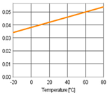
  • Material properties (including mass transfer properties) were mainly obtained from the WUFI®Pro material database [17]; hence, they were not measured. The exception is the material properties of the polyisocyanurate-insulation (PIR insulation), which was defined based on input from the producer of the façade system.
  • The moisture content in the façade system or the degree of degradation occurring throughout the ageing test were not measured.
  • Hysteresis in the concrete moisture storage function was not accounted for in the numerical simulations.
  • Changes in material properties caused by degradation or chemical processes, such as curing, were not accounted for.
  • The simulations were not validated with physical measurements.

2. Theoretical Framework

2.1. Durability of Façade Systems

Façade systems are primarily subjected to accelerated ageing to assess the durability of an exterior surface because the ability to withstand UV light, heat, water, and frost are crucial to a building’s climate shell/weather skin. However, all adjoining materials must collectively withstand climatic exposures to achieve the best possible durability.
Façade systems erected in accordance with the principle of two-stage tightening is considered a robust solution; that is, weather protection by a separate rain shield (cladding) and air/wind tightening (wind barrier). Two-stage tightening is crucial in climates with severe driving-rain exposure [18] as in large parts of the west coast of Norway [6]. The risk of moisture-related damage decreases when moisture penetrating the exterior surface (the rain shield) is allowed to dry effectively through a ventilated air gap. Façade systems with only single-stage protection against wind and precipitation (e.g., ETICS) are much more vulnerable to damage because cracking of the exterior surface can lead to leaks. Due to their limited ability to dry, even small cracks can cause moisture to accumulate in the underlying structure and lead to damage [6]. Therefore, the durability of the exterior surfaces of façade systems with only single-stage protection is of major importance. A known cause of failure is the stress that occurs when adjoining materials expand and contract differently owing to temperature changes [19,20]. For ETICS, the critical factors in this context are the stiffness and thermal expansion coefficient of the thermal insulation along with the thermal expansion coefficient of the exterior rendering. Restrained movements of the components can result in bending moments, particularly when the insulation material has a high stiffness value [21]. Other major causes of degradation are frost weathering during water-to-ice volume expansion, photodegradation caused by solar radiation, and hail [9]. These and several other climate exposure factors were further addressed by [1].
Considering only natural weather ageing to gain knowledge of the durability of materials or components is often unsatisfactory because the natural outdoor climate ageing processes take time [1]. Accelerated climate ageing tests are an option to obtain sufficiently fast and economical results. Accelerated ageing is considered a valuable practice to avoid extensive building damage owing to missing or too low resistance to climate exposure [1]. A number of accelerated climate ageing apparatuses exist and can be utilised in the laboratory according to different test methods and standards [1,22]. The purpose of accelerated climatic ageing tests is, however, not to provide an accurate estimate of service life expressed in terms of a number of years; it is to benchmark the ageing properties of different materials, systems, and techniques [6].

2.2. Accelerated Artificial Ageing of Façade Systems

To assess the durability of façade systems/assemblies, test equipment further referred to as the climate simulator is much-applied. The accelerated artificial climatic ageing in the climate simulator is described by Nordtest NT Build 495 [8]. The test was developed 50 years ago by Byggforsk (which later merged with SINTEF). After many years of experience including comparisons with natural climatic ageing of façade materials, Byggforsk developed a method description which was later approved as the Nordtest method [8].
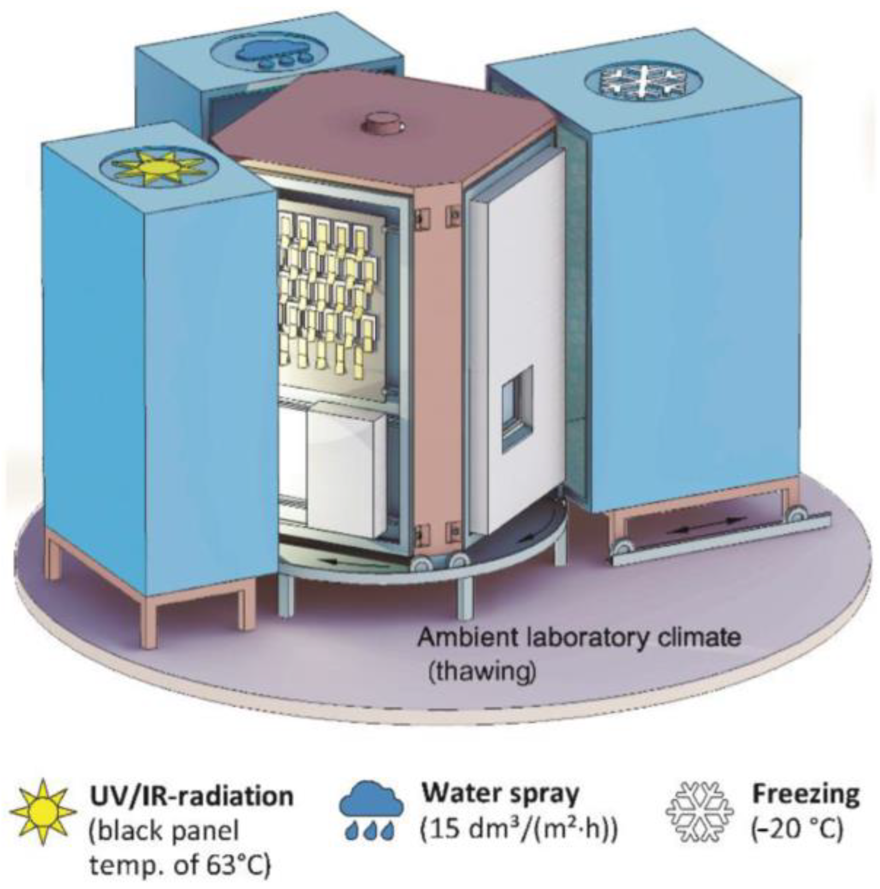
During the accelerated artificial climatic ageing test NT Build 495, specimens are positioned vertically in a rotating carousel and exposed to four degrading factors repeatedly for 1 h each (see Figure 1). In the first chamber, UV radiation is applied using fluorescent UV tubes with a relative spectral distribution in the UV band close to that of global solar irradiance. The black panel temperature rises to its designated temperature (normally 63 ± 5 °C) in 45 min from the beginning of exposure to UV light and heat radiation. If required, the black panel temperature may be chosen as 35 ± 5 °C, 50 ± 5 °C, or 75 ± 5 °C, cf. ISO 4892. The temperature is controlled using infrared halogen lamps. In the second chamber, the specimens are wetted with a spray of demineralised water. The suggested strain was 15 ± 2 L/m2·h, but various spraying conditions may be used if required. To allow water to drip off, the spraying is terminated 10 min before the specimens rotates in to the third chamber. In the third chamber, an air temperature of −20 ± 5 °C is suggested, but other specified air temperatures may be used if registered and reported. In the fourth chamber, the specimens are thawed at a laboratory climate of 23 ± 5 °C and 50 ± 10% RH.
The results of the test include information on the changes occurring during the test, the scale of the changes, and the time of occurrence. The results are assessed qualitatively, and the performance properties is often a change in performance properties—change in appearance of the specimens during the test or signs of degradation; for example, cracks, loss of gloss, or delamination.
Testing of façade solutions according to NT Build 495 [8] is currently carried out without the interior parts of the walls and without a habitable climate on the indoor side of the specimen. It is uncertain how this affects the moisture transfer at the surface and the moisture performance of the tested specimens.
Although this might be a shortcoming in the current test setup, it is a setup much-applied to assess the durability of exterior surfaces. E.g. D’Orazio et al. [23] investigated the durability of an EPS-based lightweight prefabricated construction system without focusing on the impact of the interior climate. Griciutė et al. [22] compares water adsorption of ETICS samples with samples on plaster strips but does not focus on the interior parts of the wall or the interior climate. Franzoni et al. [24] performed accelerated ageing tests to investigate the durability of a new prefabricated external thermal insulation composite board for building retrofitting without focus on the interior parts of the walls nor the indoor climate. In addition there are many examples of studies focusing on accelerated artificial ageing of small samples, such as [25,26].
Daniotti et al. [3] on the other hand, assessed the degradation evolution and the loss in hygrothermal performance of ETICS using a test setup which included all layers of the wall and a laboratory climate on the indoor side. They observed decreasing thermal resistance due to an increase of water content caused by rain penetration. They concluded that ageing, and moisture, whose content within layers is increased by ageing, affect dynamic thermal performances. The main degrading factor highlighted in this study, however, seems to be the thermal shock and dilatation-contraction events which causes blistering and deformation of the top coat. Gonçalves et al. [14] assessed the degradation and hygrothermal performance of the vacuum-insulation panel (VIP) based ETICS using a test setup which included all layers of the wall and a laboratory climate on the indoor side. They compared the test procedures defined in [16] with a new procedure to simulate solar radiation conditions. The new procedure caused defects such as loss of flatness and finishing coat microcracking, which were not found after the standard procedures, revealing the importance of studying the radiation effect on ETICS systems.
Other noteworthy studies need also be mentioned. E.g. Maia et al. [27] investigated the hygrothermal performance of a new thermal aerogel-based render applied as a component of a multilayer coating system by measuring relevant material properties and conducting hygrothermal simulations. The study highlights the importance of applying a finishing coating with low capillary absorption to reduce the water content in the inner layer and consequently the impact on the U-value of the façade. The numerical simulations highlighted that the hygrothermal risk increased in more severe climates (such as Hannover in Germany compared to Porto in Portugal) but does not focus on colder climates such as Norway. The importance of taking into account freeze–thawing ageing in colder and moderate climates is however assessed by Maia et al. [28].

2.3. Moisture Transfer in Façade Systems with Single-Stage Protection

Façade systems with only single-stage protection against wind and rain are considered particularly vulnerable to moisture damage because cracking of the exterior surface can lead to leaks and cause moisture to accumulate in the structure. Moisture from the exterior surface might also be transferred inward to the thermal insulation by diffusion when a wet surface is subjected to solar radiation. Without a ventilated air gap behind the exterior surface to enable moisture to dry effectively, moisture might accumulate in the thermal insulation behind the outer layer(s) and cause damage.
Façade systems tested in the climate simulator [8], are subjected to the degrading climatic factors on the exterior side, since the purpose of the test is to detect material degradation caused by exterior climatic exposures. The climate on the interior side is currently not controlled, as it is not within the purpose of the test to assess the overall heat resistance, general moisture transfer or durability of the interior parts of the structure. However, because the inward diffusion of moisture (caused by temperature differences) might be affected by the interior temperature, it might be necessary to control the interior climate when façade systems with only single-stage protection are tested.
In this study, we sought to evaluate the current test setup to determine whether the interior climate should be controlled. Omitting to control the interior climate (as in the current test setup) should not lead to more moisture accumulation compared to a modified test setup where the interior part of the wall is included and the indoor temperature is controlled.

2.4. Hygrothermal Simulations of Façade Systems Subjected to Accelerated Ageing

The ageing and degradation of materials and components cannot be meaningfully investigated by means of numerical simulations only [3]. To gain information on the durability, testing by either natural ageing or accelerated artificial climatic ageing must be carried out [1]. In this study, however, the objective was to investigate the moisture transfer from the exterior surface (exposed side) through the concrete and into the thermal insulation to determine whether it is necessary to control the interior climate in the climate simulator. As a theoretical approach, we assumed that the façade system was subjected to accelerated ageing for 12 months without cracking of the exterior surface and without significant changes to the hygrothermal properties. In this way, we may investigate the possible moisture accumulation within the thermal insulation, not exclusively caused by cracking of the exterior surface, and determine how the moisture transfer is affected by the interior climate.

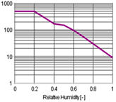
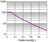
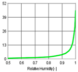
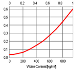
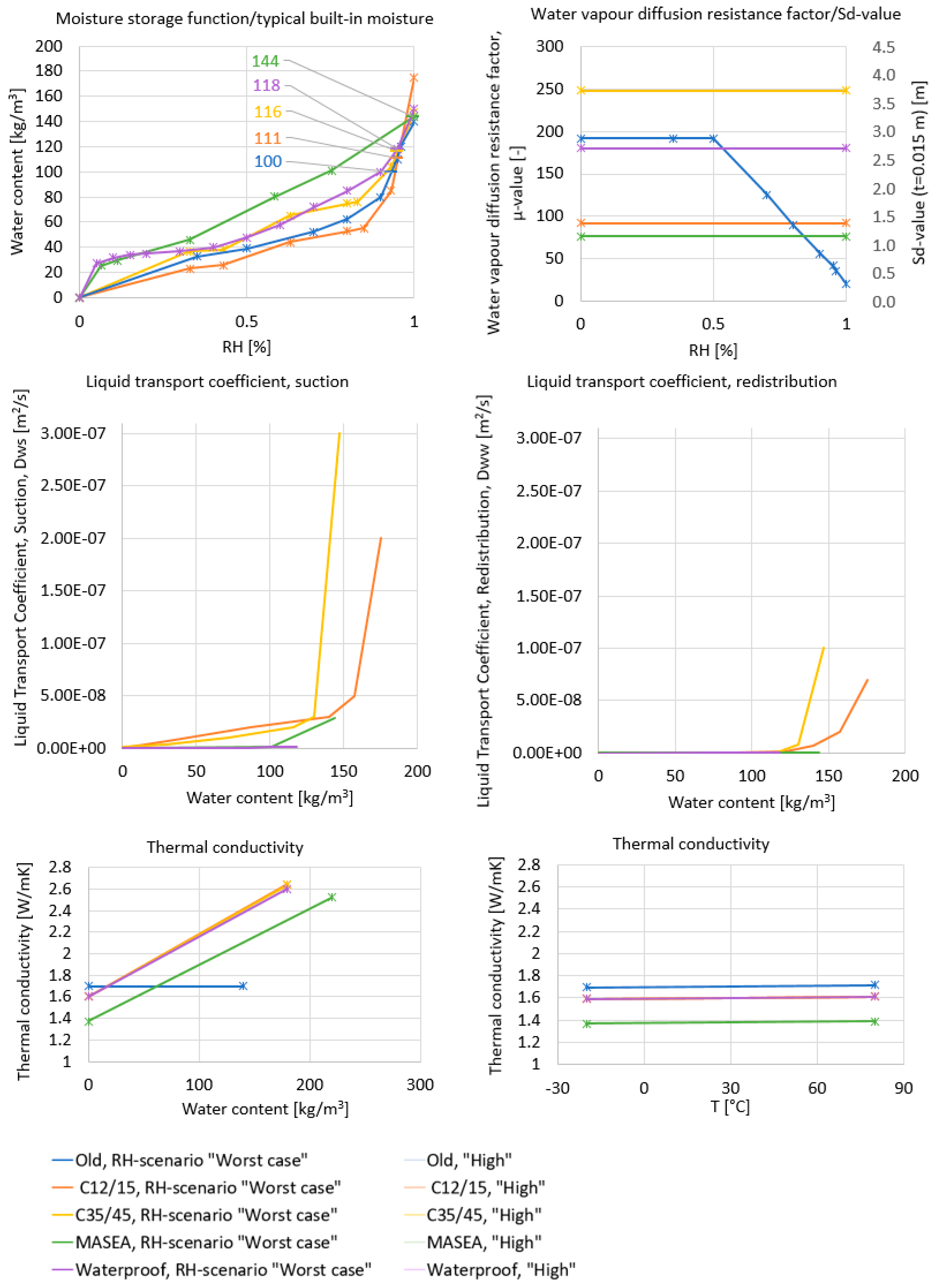
2.5. Calculating the Capillary Absorption of Rain

To calculate the capillary absorption of rain, WUFI®Pro [17] uses two material properties: Dws (moisture diffusivity coefficient for “suction” (m²/s)) and Dww (moisture diffusivity coefficient for redistribution (m²/s)). The Dws represents the capillary uptake of water when the surface of a sample element is completely wetted such as during a rain event. The suction transport is dominated by the larger capillaries because their lower capillary tension is more than compensated for by their markedly lower flow resistance. The Dww describes the dispersal of absorbed water when the wetting is complete; that is, when no more water is taken up and the water in the material is further distributed. For a building component, this corresponds to moisture transport when rain is absent. The redistribution is then dominated by the smaller capillaries because their higher capillary tension draws the water out of the larger capillaries (WUFI®Pro online help [17,29]). Moisture absorption from rain is neglected in WUFI®Pro if the “adhering fraction of rain” is set to 0 or if the rainfall is lower than 0.1 mm (it is then assumed that the rain evaporates before it is drawn into the surface). Rain is also used to determine whether capillary absorption (Dws) or capillary redistribution (Dww) is dominant in a building component. That is, for time steps where the climate data show rain, Dws will be used to calculate the capillary transport processes in the component. When rain is absent or very low, Dww is used. The Dws is generally significantly larger than Dww because redistribution is a slower process that occurs in small capillaries with high flow resistance (WUFI®Pro online help [17,29]). It is uncertain how well suited the software is to realistically replicate the uptake and distribution of rain in a multi-layered façade system with a concrete surface repeatedly subjected to rain events for a long period of time.

3. Methodology

Hygrothermal simulations were performed for a façade system subjected to accelerated artificial climatic ageing in the climate simulator. Simulations were performed according to the test setup currently used in the climate simulator and compared to a modified test setup in which the interior climate was controlled. The façade system was simulated with and without a water-repellent surface treatment on the exterior side, and five different types of concrete were compared. We assumed that the façade system was subjected to accelerated ageing for 12 months without cracking of the exterior surface and without significant changes to the hygrothermal properties. Measurements were performed in the climate simulator to determine the interior and exterior boundary conditions.

3.1. Overall Approach

The façade system chosen for this investigation is intended to be used on the exterior side of the existing timber frame walls as a part of façade refurbishment. The façade system consists of two 15-mm thick concrete layers with 30-mm PIR-insulation between them and a vapour permeable rigid mineral wool board on the back as shown in Figure 2. The system is of particular interest for this study because it is a commercial Norwegian product, it contains many layers of material and features only single-stage protection. The façade system is also previously tested according to NT Build 495 [8].
Hygrothermal simulations were performed using the commercial software WUFI®Pro version 6.4 [17]. Due to the fact that the simulation program addresses one-dimensional heat and moisture transport, 3D effects from frameworks, steel and hat profiles, fasteners, joints, and edges were neglected. The simulations were performed for two different test setups (i.e., the current setup and the modified setup) (see Figure 2).
The current setup constituted the test setup currently used to carry out accelerated ageing tests in the climate simulator; the façade systems are mounted in the climate simulator on a provisional wall consisting of two plywood boards with an air cavity in between. The exterior and interior boundary conditions were determined from measurements in the climate simulator. The interior climate was therefore not controlled but followed fluctuations in temperature and RH from exposure on the exterior side.
The modified setup constituted a hypothetical situation in which the interior climate in the climate simulator is controlled at 21 °C/50% RH. The objective of this kind of modification is to create a climate that is more representative of heated buildings and the heat and moisture transfer that occurs within building façades when exposed to a varying exterior climate. In the modified setup, the provisional wall was replaced with an insulated timber frame wall with a vapour barrier on the interior side. The exterior boundary conditions were the same as those in the current setup. For the interior boundary conditions, a constant temperature and RH were chosen.

3.2. Material Properties and Initial Conditions

The hygrothermal properties of the materials used in the façade system were not documented or published by the manufacturer. Due to the fact that the properties of concretes vary significantly, five different types of concrete were compared as shown in Table 1. The concrete and other materials in the façade system were selected from the WUFI®Pro material database. An overview of the material properties is provided in Figure A1 and Table A1 in Appendix A. The initial temperature was set to 5 °C. The typical built-in moisture contents suggested by WUFI®Pro were used as the initial condition as shown in Table A1.

3.3. Boundary Conditions

Climate data files were created using the CreateClimateFile.xlsm Ver.: 2.6 supplied with the WUFI®Pro software [17]. Owing to the rapidly changing conditions in the climate simulator, a 1-h time step was not appropriate for the boundary conditions, and shorter time steps were adapted. In this case, 1/10 h (6-min intervals) proved to be an appropriate resolution. The climate data used in the simulations consisted of a 4-h period which was repeated for 12 months.
The same exterior boundary conditions were used in the simulations of both the current and modified test setups. The conditions were determined based on the measurements of temperature and RH performed in SINTEF’s artificial climate simulator (see Appendix B). The temperature and RH variations used in the simulations are listed in Table 2 and are depicted in Figure 3. Both test setups were simulated with and without a water-repellent surface treatment on the exterior side; that is, allowing or excluding rain adsorption. The heat and moisture transfer coefficients on the exterior side were set to zero because the boundary conditions were determined from temperatures measured at the surface. The RH was measured only in the airgap behind the test element in the climate simulator. Therefore, two different RH-scenarios, “worst case” and “high”, were determined and used as boundary conditions at the exterior surface.
The interior boundary conditions used in the simulations of the current test setup were determined from the measurements performed in SINTEF’s climate simulator (see Appendix B). The temperature and RH variations are shown in Table 2 and depicted in Figure 3. The heat transfer coefficient was set to 8.0 W/m2K, and the corresponding moisture transfer coefficient was determined by WUFI®Pro. In the simulations of the modified test setup, the interior boundary condition was set as constant at 21 °C and 50% RH.

3.4. Parameter Study

As described in previous chapters, hygrothermal simulations were performed using two different test setups, two different RH scenarios at the exterior side, and five different types of concrete. Simulations were also performed with and without water-repellent surface treatment on the exterior surface. An overview of the different variants is provided in Table 3.
Additional simulations were performed for:
  • an alternative plywood board (Plywood USA);
  • an alternative generic air layer (air layer of 100 mm without additional moisture capacity);
  • rain loads lower than 15 L/m2.h (i.e., 1.5, 0.11, and 0.01);
  • adhering fractions of rain between 0 and 1.

4. Results

Hygrothermal simulations were performed for a façade system subjected to accelerated ageing in the climate simulator. The results of the simulations of the current test setup show that the variation of the moisture content in the PIR insulation varied significantly depending on the type of concrete (see Figure 4 and Table 4). Minor differences occurred when comparing the two RH-scenarios “high” and “worst case”. The water-repellent surface treatment in the simulations (including or excluding the liquid uptake of rain) affected the results differently for the various types of concrete. Two types of concrete achieved a low moisture content in the PIR insulation when surface treatment was applied and higher moisture content when rain was allowed to penetrate the surface. Two types of concrete resulted in high moisture content even though surface treatment was applied and somewhat lower moisture content when rain was included. The modified test setup resulted in higher moisture contents in the PIR-insulation than the current test setup, in all the simulated cases.

5. Discussion

This study investigates the risk of moisture accumulation in a multi-layered façade system exposed to accelerated ageing in the climate simulator according to NT Build 495 [8], and considers the need to change the current test setup by controlling the interior climate. The results and answers to the research questions are discussed in the following section.

5.1. Moisture Accumulation in a Façade System Exposed to Accelerated Ageing

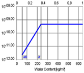
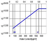
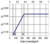
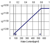
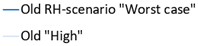
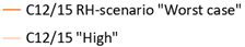
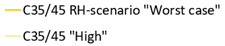
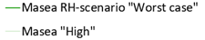
The hygrothermal simulations show that moisture may accumulate in the thermal insulation; however, this is strongly dependent on the concrete quality and whether a water-repellent surface treatment is applied. The C12/15 and C35/45 concretes have the greatest ability to transfer moisture by capillary action (large liquid transfer coefficients) and result in the largest moisture accumulation. The typical application of these concretes is not stated in the WUFI®Pro material database, and the correspondence to the concrete in the façade system is unknown. However, the high moisture uptake suggests that they will not work well in a façade with single-stage protection.
The results also show, in line with previous research [30], that applying a water-repellent surface treatment contributes to prevent moisture accumulation in the façade system. When rain is allowed to penetrate the surface (no water-repellent surface treatment is applied), all relevant concrete characteristics result in high moisture content in the PIR insulation. When a surface treatment is applied (liquid uptake of rain is excluded), the results vary more. The MASEA and Old concretes results in a low moisture content, the waterproof concrete has a low or a moderate moisture accumulation depending on the RH-scenario, and the C12/15 and C35/45 concretes results in high moisture content.
Comparing the results for the C12/15 and C35/45 concrete qualities with and without a surface treatment, is interesting. When rain is allowed to penetrate the surface, the concretes result in lower moisture accumulation in the PIR insulation than when rain is excluded. This behaviour is caused by the mathematical model and the procedure for calculating the capillary absorption of rain. In short, when rain is applied to the component for capillary absorption, the amount of water absorbed during the time step depends on the capillary properties of the surface material, the current saturation state of the material, and the amount of rain available for absorption. Rain is also used to determine whether capillary absorption or capillary redistribution processes are currently dominant in the building component. During the time steps rain is applied, the liquid transport coefficients for suction are used to compute all the capillary transport processes in the component. Otherwise, the liquid transport coefficients for redistribution are used. Due to the fact that the surfaces of the two types of concrete are already close to saturation when rain is applied for adsorption, most of the rain runs off instead of being absorbed. The rate of the moisture transfer in the other capillary material layers in the component, however, is increased. As a result, more moisture is transferred from the PIR insulation towards the interior side during rain events, resulting in a somewhat lower final moisture content in the PIR insulation despite the lack of a water-repellent surface treatment. It is uncertain whether the qualities of these concretes are suitable for the exterior surface of façades with only single-stage protection because of the risk of degradation by freezing and thawing.

5.2. Controlling the Interior Climate

Artificial accelerated ageing of building materials and products are performed according to NT Build 495 [8]. The test is applied to façade systems to assess the durability of their exterior surfaces as withstanding UV light, heat, water, and frost and are crucial to a buildings’ climate shell/weather skin. In the current test setup, façade systems are mounted on a provisional wall and subjected to degrading climatic factors on the exterior side. One concern with the current test setup is that the façade systems are tested without the interior parts of the wall assemblies and without a habitable indoor climate. The concern is that that this setup might negatively affect the moisture performance. However, the simulations show that the current test setup results in lesser moisture accumulation in the thermal insulation compared to that of the modified test for all the investigated types of concrete. This is mainly because the interior temperature in the current test setup follows variations in the exterior surface temperature more closely than in the modified setup where the interior parts of the wall is included and the indoor climate is controlled at 21 °C. The interior parts of the wall also limit the drying to the interior side to a certain extent. According to Daniotti et al. [3], more water absorption detriments both ageing and thermal performance of ETICS.

5.3. Limitations of The Study

In this study, we assess the possible moisture accumulation in the PIR insulation in a façade solution that may occur without damage/degradation at the exterior surface. It was therefore assumed that the façade system was subjected to accelerated ageing for 12 months without cracking of the exterior surface and without significant changes to the hygrothermal material properties. To gain information on the durability, testing by either natural ageing or accelerated artificial climatic ageing must be carried out.
Modelling the complex coupled heat and moisture transfer processes in building components always involves simplification of reality. Some materials (e.g., concrete) do not conform to the simplified transport equations and change their material data depending on their present and past moisture content. Materials with a pronounced hysteresis in their moisture storage function (e.g., concrete) may not be sufficiently described using an averaged moisture-storage function. The total moisture transfer resulting from the combination of liquid and vapour transport processes under varying thermal conditions, as in the climate simulator, is also difficult to calculate because the two flows cannot be divided in laboratory experiments. The errors caused by these general inaccuracies may be negligible or serious. To determine the reliability of the calculations, the results should be compared with measurements.
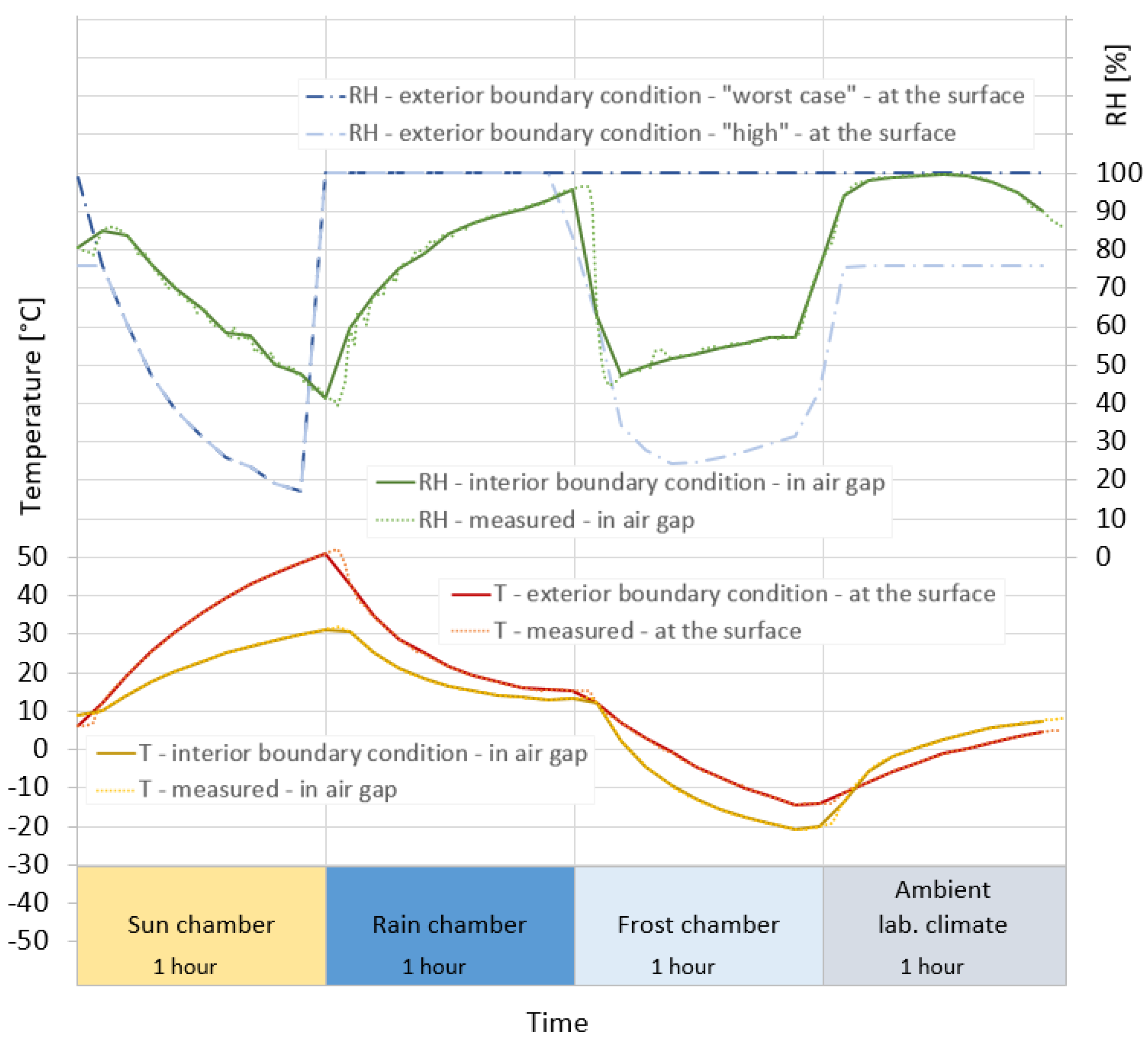
The boundary conditions applied in the hygrothermal simulations were determined based on measurements of temperature and RH in the climate simulator. Due to the fact that the RH humidity at the exterior surface (exterior boundary condition) was lacking, two different RH scenarios were determined from measurements of RH in the air gap behind the test samples: “Worst case” and “High”. The two determined scenarios were considered conservative; that is, higher than what the measurements indicated, in particular during exposure to the ambient laboratory climate. The two conservative scenarios were considered appropriate for the scope of this study; however, the moisture accumulation may be somewhat overestimated in this study because of this inaccuracy. If the purpose of the simulations had been to determine the amount of moisture accumulation more precisely, more detailed measurements of the boundary conditions and material properties would have been necessary.
The material properties of the products in the façade system in this study have not been documented. Ideally, the material properties should have been determined experimentally under similar boundary conditions as in practical use. This was beyond the scope of this study. Therefore, five different types of concrete derived from the WUFI®Pro material database were compared. The correspondence of these concretes to the actual material properties of the concrete in the façade system is unknown.
As discussed in this chapter, there were inaccuracies in the calculations caused by the limitations in the hygrothermal model, the determination of boundary conditions, and the lack of documented material properties. A main concern is the unknown material properties of the concrete and the modelling of rain absorption at the surface. The ability of the simulation software to realistically replicate the moisture transfer in multi-layered façade systems exposed to rain events over long time periods is questionable. Although these inaccuracies must be acknowledged when interpreting the calculated moisture accumulation, they are considered to be of less importance for the main results and conclusions in this article.

6. Conclusions

The hygrothermal simulations of a façade system exposed to accelerated ageing testing according to NT Build 495 [8], show that the amount of moisture accumulation depends strongly on the type of concrete and whether a water-repellent surface treatment is applied. The results show that a water-repellent surface treatment contributes to preventing moisture accumulation in the façade system. The two types of concrete with the greatest ability to absorb moisture by capillary forces resulted in the highest moisture content in the thermal insulation at the end of the test. It is however uncertain whether these two types of concrete are suitable for the façade system with only single-stage protection because of the high moisture uptake at the exterior surface. The material properties of the products in the façade system in this study have not been determined through testing. To calculate the moisture accumulation accurately, the material properties must be determined experimentally under similar boundary conditions as in practical use.
The current test setup resulted in lower moisture accumulation compared to that of the modified test setup for all the investigated types of concrete. More water absorption may lead to accelerated degradation and negatively affect the thermal performance.

Author Contributions

Conceptualization, S.K.A., B.T. and T.K.; methodology, S.K.A., B.T. and T.K.; formal analysis, S.K.A., B.T. and T.K.; investigation, S.K.A.; data curation, S.K.A.; writing—original draft preparation, S.K.A.; writing—review and editing, S.K.A., B.T. and T.K.; visualization, S.K.A.; supervision, B.T. and T.K.; funding acquisition, B.T. and T.K. All authors have read and agreed to the published version of the manuscript.

Funding

This research and the APC were funded by SINTEF, The Research Council of Norway, and several partners through the Centre for Research-based Innovation ‘Klima 2050’, grant number 237859.

Institutional Review Board Statement

Not applicable.

Informed Consent Statement

Not applicable.

Acknowledgments

The authors would like to extend a special thanks to Sivert Uvsløkk and Egil Rognvik for conducting and assessing the measurements of temperature and RH performed in the climate simulator, and to CAD operator Anne Eliassen for drawing Figure 2.

Conflicts of Interest

The authors declare no conflict of interest.

Appendix A

Figure A1. Material properties of the five types of concrete used in the simulations. The graphs are created by the authors based on selected material data from the WUFI®Pro material database [17].
Buildings 11 00568 g0a1
Table A1. Properties of materials used in simulations. The material properties are mainly obtained from the WUFI®Pro material database [17]. The exception is the material properties of the PIR insulation, which is defined based on input from the producer of the façade solution. The images illustrating the material properties are obtained from the WUFI®Pro Software [17].
MaterialPIRMineral Wool BoardPlywoodPlywoodMineral WoolVapour BarrierAir Cavity
Name of material in the WUFI®Pro material databaseUser defined *Isover Ultimate
Klemmfilz–035
(Fraunhofer-IBP)
Plywood low
(North America database)
Plywood USA (North America database)Mineral wool (heat cond.: 0.04 W/mK)
(Fraunhofer-IBP)
Vapour retarder
sd = 10 m
(Fraunhofer-IBP)
Air layer 100 mm ** (generic materials)
Thickness (m)0.030.050.0150.0150.1- (0.001)0.1
sd-value (m)1.380.05RH0%: 7.4,
00%: 0.14
RH0%: 16.3,
100%: 0.33
0.13100.015
Water vapour
diffusion
resistance factor,
µ (-),
RH dependent
461 Buildings 11 00568 i001
493-9
Buildings 11 00568 i002
1088-22
1.310,0000.15
Moisture storage function (kg/m3)
RH dependent
Buildings 11 00568 i003 Buildings 11 00568 i004 Buildings 11 00568 i005 Buildings 11 00568 i006 Buildings 11 00568 i007 Buildings 11 00568 i008 Buildings 11 00568 i009
Liquid transport coefficient,
suction,
Dws (m2/s)
dependent on moisture content (kg/m3)
****** Buildings 11 00568 i010 Buildings 11 00568 i011*********
Liquid transport coefficient,
redistribution, Dww (m2/s)
dependent on moisture content (kg/m3)
****** Buildings 11 00568 i012 Buildings 11 00568 i013*********
Thermal
conductivity,
λ (W/mK),
moisture
dependent (kg/m3)
Buildings 11 00568 i014
0.023–0.6
Buildings 11 00568 i015
0.034–0.6
0.0680.084 Buildings 11 00568 i016
0.04–0.6
2.30.59
Thermal
conductivity,
λ (W/mK),
temperature
dependent
Buildings 11 00568 i017
0.017–0.037
Buildings 11 00568 i018
0.028–0.048
Buildings 11 00568 i019
0.062–0.082
Buildings 11 00568 i020
0.078–0.098
Buildings 11 00568 i021
0.034–0.054
~2.30.59
Initial moisture (kg/m3) ****1.80.555701.80.0020.01
* The material properties of the PIR insulation are defined based on input from the producer of the façade solution. The sd-value, µ-value, and thermal conductivity were specified. The moisture storage function and initial moisture content are based on properties provided by the WUFI®Pro material database. ** According to WUFI®, generic air layers can be used for unventilated air cavities between non-metallic surfaces. The effective material parameters of the air layers describe the total heat transport (owing to heat conduction, free convection, and radiative transport), and total vapour transport (owing to diffusion and free convection). For each layer thickness, the database provides two air layers with different moisture storage functions: a standard air layer and an air layer without additional moisture capacity. The latter has a lower (more realistic) moisture storage function which corresponds to the moisture contents of a 20 °C warm air layer. The moisture contents and hygric inertia of these air layers are at a realistic level; however, they may prove numerically challenging. The standard layers use the program’s default moisture storage function, resulting in an unrealistically high moisture content for an air layer. These moisture contents are less demanding on the numerics, but should not be used for evaluating the construction. *** Not included in WUFI®Pro material database since the respective materials are considered not to be capillary active. **** The typical built-in moisture contents suggested by WUFI®Pro were used as initial conditions.

Appendix B

Appendix B.1. Measurements

Temperature and RH measurements were performed on two test elements subjected to accelerated artificial ageing in SINTEF’s climate simulator. The two test elements consisted of parts of a façade system previously subjected to accelerated ageing according to NT Build 495 [8]. The two test elements were of the same build as the façade solution investigated in the simulations but without the mineral wool board and the provisional wall. The measured data were considered representative for the façade solution investigated in the simulations in this study.
Temperatures were measured on the exterior surfaces and in the air gap behind the test elements. The RH was measured in the air gap behind the two test elements. The sensors on the outside (outdoor climate) were positioned on the surface of the test elements, and the sensors on the back of the test elements (indoor climate) were positioned in the air gap at the back. The RH on the surface of the test element used in the simulation was partly calculated and partly determined by assessment as described below.
Based on the measured data, representative climate data for 4-h were constructed which corresponded to an entire cycle in the climate simulator. In the simulations, these four hours were repeated for one year (see Figure 2 in the main text). The temperature and RH were measured with minute values because the changes in the climate simulator during a 4-h period were expected to vary continuously. In WUFI®Pro, hourly values are commonly used. In these simulations, 0.1-h (6 min) was considered to be a suitable time step (see Figure 2 in the main text).
The exterior boundary conditions (applied in the simulations of both the current and the modified test setups) are determined based on temperatures and the RH measured at the surface of the test element. The temperatures used were the same as those measured in the middle of the surface of one of the test elements. The selected measurement period was 20 March 2020, 15.00 to 18.54. The measured values were converted from minute values to 6-min values. The software WUFI®Pro calculates the surface temperature of a sample if the air temperature and radiation data are provided. In this case, the measurements of the surface temperature were used directly to account for solar radiation.
As there were no measurements of RH on the exterior surface of the test elements, the RH on the surface (exterior boundary condition) of the façade solution in the simulation was partly calculated and partly determined by assessment. Two conservative climate scenarios were determined and used in the simulations: “high” and “worst case”. Both climate scenarios represented RH variations which were probably higher than what would have been measured. By making further assessments/assumptions, a third climate scenario with a lower RH can be determined. A lower RH would result in a lower moisture content in the PIR-insulation. Due to the fact that this will only have a positive effect and does not affect the main results in the report, these simulations were not performed. The RH on the surface of the façade element was first calculated from measurements of RH and temperatures in the middle of the air space at the back of the test element along with the temperatures measured on the surface of one of the test elements. The RH was calculated using equations for the water vapour saturation pressure as a function of temperature. The equations given in the WUFI®Pro online help were used [17,29]. In the rain chamber, the RH at the front of the test element was considered to be 100%. There was more uncertainty associated with the RH on the front of the test element when it was in the freezing chamber or in the laboratory room. In the freezing chamber, it is conceivable that a water film froze on the surface of the test element. The RH will then be close to 100% which is far higher than the calculated RH based on measurements in the air behind the test element. In the laboratory room, the RH in the airspace behind the test element was 100%. The calculated RH on the front will then be over 100% and can therefore not be used. However, measurement of RH and temperature in the laboratory near the climate simulator for the relevant measurement period showed a low RH (3–8% at 20 °C). The calculated RH for the test element surface based on the vapour pressure measured during the period when the test element was in the laboratory decreased from 100% to 7% RH in 1 h. The correct RH was considered to be somewhere between these extremes. Due to the fact that there was some uncertainty associated with the RH on the exterior surface, two different climate scenarios were used in the simulations in this study (see Table 2 and Figure 3 in the main text).

Appendix B.2. Rain

In the climate simulator, tested façade systems are subjected to a water spray for 50 min each quarter hour. The amount of rain in the simulation was therefore set at 15 L/m2.h, which corresponds to the 15 mm of rain per hour of the climate simulator. The proportion of rain that hit the surface of the façade solution (“adhering fraction of rain”) was set to 1. This means that all the rain is made available to the surface. The proportion of rain drawn into the material surface in the simulation then is dependent on the surface layer and the moisture transfer properties of the concrete.

Appendix B.3. Surface Treatment on Exterior Surface

In the simulations, two different situations were studied (see Table 4). First it was assumed that the surfaces of the façade solution were treated with a water-repellent diffusion open-surface treatment; in this case the water hitting the exterior surface in the rain chamber was not drawn into the surface capillary. Then, it was assumed that the surface of the façade solution was untreated and thus that the water that hit the exterior surface in the rain chamber was drawn into the surface depending on the properties of the concrete.

Appendix B.4. Boundary Conditions on Interior Side

In simulations of the current test setup, the measured temperature and RH in the air gap at the back of the test element were used for the interior surface of the façade solution. The selected measurement period was 20 March 2020, 15.00 to 18.54. The measured values were converted from minute values to 6-min values. A surface transfer resistance of 0.13 m2 K/W was applied to the interior surface.
In simulations of the modified test setup, the provisional wall was replaced with 100-mm mineral wool and a vapour barrier, and a constant climate of 21 °C and 50% RH were used for the interior surface of the façade solution. A surface transfer resistance of 0.13 m2K/W was applied to the interior surface.

References

  1. Jelle, B.P. Accelerated climate ageing of building materials, components and structures in the laboratory. J. Mater. Sci. 2012, 47, 6475–6496. [Google Scholar] [CrossRef] [Green Version]
  2. Hanssen-Bauer, I.; Førland, E.J.; Haddeland, I.; Hisdal, H.; Mayer, S.; Nesje, A.; Nilsen, J.E.Ø.; Sandven, S.; Sandø, A.B.; Sortberg, A.; et al. Climate in Norway 2100 a Knowledge Base for Climate Adaptation; The Norwegian Centre for Climate Services (NCCS): Bergen, Norway, 2017. [Google Scholar]
  3. Daniotti, B.; Paolini, R.; Re Cecconi, F.R. Effects of Ageing and Moisture on Thermal Performance of ETICS Cladding. In Durability of Building Materials and Components; Building Pathology and Rehabilitation; de Freitas, V.P., de Delgado, J.M.P.Q., Eds.; Springer: Berlin, Heidelberg, 2013; pp. 127–171. [Google Scholar]
  4. Ibrahim, M.; Wurtz, E.; Biwole, P.; Achard, P.; Sallee, H. Hygrothermal performance of exterior walls covered with aerogel-based insulating rendering. Energy Build. 2014, 84, 241–251. [Google Scholar] [CrossRef]
  5. Ihara, T.; Jelle, B.P.; Gao, T.; Gustavsen, A. Aerogel granule aging driven by moisture and solar radiation. Energy Build. 2015, 103, 238–248. [Google Scholar] [CrossRef]
  6. Kvande, T.; Bakken, N.; Bergheim, E.; Thue, J.V. Durability of ETICS with Rendering in Norway—Experimental and Field Investigations. Buildings 2018, 8, 93. [Google Scholar] [CrossRef] [Green Version]
  7. Jelle, B.P.; Nilsen, T.-N.; Hovde, P.J.; Gustavsen, A. Accelerated climate aging of building materials and their characterization by Fourier transform infrared radiation analysis. J. Build. Phys. 2011, 36, 99–112. [Google Scholar] [CrossRef]
  8. NT Build 495. Building Materials and Components in the Vertical Position: Exposure to Accelerated Climatic Strains; Nordtest: Espoo, Finland, 2000. [Google Scholar]
  9. Francke, B.; Zamorowska, R. Resistance of External Thermal Insulation Composite Systems with Rendering (ETICS) to Hail. Materials 2020, 13, 2452. [Google Scholar] [CrossRef]
  10. Asphaug, S.K.; Jelle, B.P.; Gullbrekken, L.; Uvsløkk, S. Accelerated ageing and durability of double-glazed sealed insulating window panes and impact on heating demand in buildings. Energy Build. 2016, 116, 395–402. [Google Scholar] [CrossRef]
  11. Fufa, S.M.; Labonnote, N.; Frank, S.; Rüther, P.; Jelle, B.P. Durability evaluation of adhesive tapes for building applications. Constr. Build. Mater. 2018, 161, 528–538. [Google Scholar] [CrossRef]
  12. Rüther, P.; Jelle, B.P. Color changes of wood and wood-based materials due to natural and artificial weathering. Wood Mater. Sci. Eng. 2013, 8, 13–25. [Google Scholar] [CrossRef]
  13. Wegger, E.; Jelle, B.P.; Sveipe, E.; Grynning, S.; Gustavsen, A.; Baetens, R.; Thue, J.V. Aging effects on thermal properties and service life of vacuum insulation panels. J. Build. Phys. 2011, 35, 128–167. [Google Scholar] [CrossRef] [Green Version]
  14. Gonçalves, M.; Simões, N.; Serra, C.; Flores-Colen, I. Laboratory assessment of the hygrothermal performance of an external vacuum-insulation composite system. Energy Build. 2021, 254, 111549. [Google Scholar] [CrossRef]
  15. Hens, H.S.L.C.; Mukhopadhyaya, P.; Kumaran, M.; Dean, S.W. Modeling the Heat, Air, and Moisture Response of Building Envelopes: What Material Properties are Needed, How Trustful Are the Predictions? J. ASTM Int. 2007, 4, 460. [Google Scholar] [CrossRef]
  16. EOTA European Assessment Document EAD 040083-00-0404. External Thermal Insulation Composite Systems (ETICS) with Renderings. 2019. Available online: https://www.eota.eu/download?file=/2014/14-04-0083/for%20ojeu/ead%20040083-00-0404_ojeu2020.pdf (accessed on 1 November 2021).
  17. Fraunhofer IBP. WUFI, WUFI®Pro 6.5. 2021. Available online: https://wufi.de/en/ (accessed on 17 August 2021).
  18. Kvande, T.; Lisø, K.R. Climate adapted design of masonry structures. Build. Environ. 2009, 44, 2442–2450. [Google Scholar] [CrossRef]
  19. Passa, D.S.; Sotiropoulou, A.B.; Pandermarakis, Z.G.; Mitsopoulos, G.D. Thermal and Drying Cyclic Loading for Cement Based Mortars and Expanded Polystyrene Foam Layers. Appl. Mech. Mater. 2012, 204–208, 3648–3651. [Google Scholar] [CrossRef]
  20. Lisø, K.R.; Kvande, T.; Thue, J.V. High-performance weather-protective flashings. Build. Res. Inf. 2005, 33, 41–54. [Google Scholar] [CrossRef]
  21. De Freitas, S.S.; de Freitas, V.P. Cracks on ETICS along thermal insulation joints: Case study and a pathology catalogue. Struct. Surv. 2016, 34, 57–72. [Google Scholar] [CrossRef]
  22. Griciutė, G.; Bliūdžius, R.; Norvaišienė, R. The Durability Test Method for External Thermal Insulation Composite System used in Cold and Wet Climate Countries. J. Sustain. Arch. Civ. Eng. 2013, 1, 50–56. [Google Scholar] [CrossRef]
  23. D’Orazio, M.; Stipa, P.; Sabbatini, S.; Maracchini, G. Experimental investigation on the durability of a novel lightweight prefabricated reinforced-EPS based construction system. Constr. Build. Mater. 2020, 252, 119134. [Google Scholar] [CrossRef]
  24. Franzoni, E.; Pigino, B.; Graziani, G.; Lucchese, C.; Fregni, A. A new prefabricated external thermal insulation composite board with ceramic finishing for buildings retrofitting. Mater. Struct. 2015, 49, 1527–1542. [Google Scholar] [CrossRef]
  25. Parracha, J.L.; Borsoi, G.; Veiga, R.; Flores-Colen, I.; Nunes, L.; Garcia, A.R.; Ilharco, L.M.; Dionísio, A.; Faria, P. Effects of hygrothermal, UV and SO2 accelerated ageing on the durability of ETICS in urban environments. Build. Environ. 2021, 204, 108151. [Google Scholar] [CrossRef]
  26. Pereira, M.C.; Soares, A.; Flores-Colen, I.; Correia, J.R. Influence of Exposure to Elevated Temperatures on the Physical and Mechanical Properties of Cementitious Thermal Mortars. Appl. Sci. 2020, 10, 2200. [Google Scholar] [CrossRef] [Green Version]
  27. Maia, J.; Pedroso, M.; Ramos, N.; Pereira, P.; Flores-Colen, I.; Gomes, M.G.; Silva, L. Hygrothermal performance of a new thermal aerogel-based render under distinct climatic conditions. Energy Build. 2021, 243, 111001. [Google Scholar] [CrossRef]
  28. Maia, J.; Ramos, N.M.M.; Veiga, R. Assessment of test methods for the durability of thermal mortars exposure to freezing. Mater. Struct. 2019, 52, 112. [Google Scholar] [CrossRef]
  29. Künzel, H.M. Simultaneous Heat and Moisture Transport in Building Components; One- and Two-Dimentional Calculation Using Simple Parameters; IRB-Verlag: Stuttgart, Germany, 1995; ISBN 3-8167-4103-7. [Google Scholar]
  30. Slapø, F.; Kvande, T.; Bakken, N.; Haugen, M.; Lohne, J. Masonry’s Resistance to Driving Rain: Mortar Water Content and Impregnation. Buildings 2017, 7, 70. [Google Scholar] [CrossRef] [Green Version]
Figure 1. Climate simulator with four climate zones used for testing according to NT Build 495 as illustrated by Kvande et al. [6]. The mid-section is rotating clockwise.
Buildings 11 00568 g001
Figure 2. Test setups applied in the hygrothermal simulations. In the current setup, the façade system was erected on a provisional wall and the interior climate varied depending on the exterior exposure. In the modified setup, the provisional wall was replaced with a mineral wool board and an interior vapour barrier. The exterior boundary conditions were the same as those of the current setup, but a constant temperature and RH were set at the interior boundary.
Buildings 11 00568 g002
Figure 3. Interior boundary conditions used in the current test setup and exterior boundary conditions used in both the current and the modified test setup. The 4-h period (6-min intervals) corresponds to one rotation in the climate simulator and was repeated for 12 months in the simulations.
Buildings 11 00568 g003
Figure 4. Moisture content in the PIR insulation of the façade solution subjected to accelerated ageing in climate simulator. The left and the right diagrams show the current and the modified test setups, respectively. The upper and lower diagrams show results with and without a water-repellent surface treatment, respectively. The five types of concrete are depicted in different colours. The light and dark colours distinguish between the two RH-scenarios.
Buildings 11 00568 g004
Table 1. Types of concrete used in hygrothermal simulations.
Name of Concrete in This StudyName in WUFI®Pro DatabaseSourceQuality of Concrete
(WUFI®Pro Material Database)
Colours in Results
OldConcrete
w/c = 0.4
LTH Lund University, SwedenMaterial data applies to several years’ old concrete and cannot be used to address built-in moisture. Liquid transfer coefficients are not included. Buildings 11 00568 i022
C12/15Concrete, C12/15Fraunhofer-IBPNo additional information Buildings 11 00568 i023
MASEAConcreteMASEA
Database, Germany
No additional information Buildings 11 00568 i024
C35/45Concrete, C35/45Fraunhofer-IBPNo additional information Buildings 11 00568 i025
WaterproofConcrete, w/c = 0.5Fraunhofer-IBPMoisture permeability of mature concrete. With respect to the overall moisture transmission, this concrete is roughly equivalent to waterproof types of concrete (appropriate thickness and reinforcement required). Buildings 11 00568 i026
Table 2. Exterior and interior boundary conditions used in the hygrothermal simulations for the current and the modified test setups.
Exterior climate
Current
and
modified test setup
At
exterior surface *
TTemperature measured on exterior surface of test element (red). Solar radiation is therefore not used as a boundary condition. (WUFI uses air temperature and solar radiation to calculate surface temperatures.)
RHRH determined from measurements, (Appendix B)RH-scenario “worst case”
(dark blue)
Sun: RH calculated from the RH measured in air gap behind test element
Rain: RH set to 100%
Frost: RH set to 100%
Lab: RH set to 100%
RH-scenario “high”
(light blue)
Sun: RH calculated from RH measured in air gap behind test element
Rain: RH set to 100%
Frost: RH calculated from T/RH measured in air gap behind test element
Lab: RH reduced to 76%
(value between calculated RH (from measured vapour pressure in air gap behind test element) and measured vapour pressure in the laboratory)
Rain15 L/m2·h (adhering fraction of rain = 1)
Interior climate
Current test setup
Indoor air **TTemperature as measured in airspace behind test element (yellow)
RHRH as measured in airspace behind test element (green)
Interior climate
Modified test setup
Indoor air **T21 °C
RH50%
* Heat and moisture transfer coefficients = 0 W/m2K (because T/RH was measured at the surface). ** Heat transfer coefficient = 8.0 W/m2K. The corresponding moisture transfer coefficient was determined by WUFI®Pro.
Table 3. Simulation variants.
Types of ConcreteCurrent Test SetupModified Test Setup
Water-Repellent Surface TreatmentNo Surface TreatmentWater-Repellent Surface TreatmentNo Surface Treatment
“Worst Case”“High”“Worst Case”“High”“Worst Case”“High”“Worst Case”“High”
Old *
C12/15
MASEA
C35/45
Waterproof
* Liquid transfer coefficient is not included for this concrete.
Table 4. Moisture content in PIR insulation after one year of accelerated ageing.
Type of ConcreteCurrent Test SetupModified Test Setup
Water-Repellent
Surface Treatment
No Surface TreatmentWater-Repellent
Surface Treatment
No Surface Treatment
“Worst Case”“High”“Worst Case”“High”“Worst Case”“High”“Worst Case”“High”
Old *12.66.912.66.934.023.033.623.0
C12/1599.095.287.384.3176.1171.4176.1171.4
MASEA3.02.191.691.15.122.8203.1202.8
C35/45104.3100.888.285.3187.9183.4190.8187.4
Waterproof55.293.5100.497.4128.25.1182.4178.6
* Liquid transfer coefficients are not included for this concrete; results are thus equal both with and without surface treatment.
Publisher’s Note: MDPI stays neutral with regard to jurisdictional claims in published maps and institutional affiliations.

