Article

Stress Distribution in Microregion of Core–Shell Structure Lightweight Aggregate Concrete

1
State Key Laboratory of Environmental Friendly Energy Materials, School of Materials Science and Technology, Southwest University of Science and Technology, Mianyang 621010, China
2
Engineering and Architecture, Foshan University of Science and Technology, Foshan 528200, China
3
College of Science and Engineering, Flinders University, Bedford Park, Adelaide, SA 5042, Australia
*
Author to whom correspondence should be addressed.
Buildings 2021, 11(11), 540; https://doi.org/10.3390/buildings11110540
Submission received: 18 October 2021 / Revised: 5 November 2021 / Accepted: 12 November 2021 / Published: 15 November 2021
(This article belongs to the Topic Architectures, Materials and Urban Design)

Abstract

:
An in-depth understanding of the effect of cordierite/belite core–shell structure lightweight aggregate (CSLWA) on the mechanical performance of LWA concrete (LWAC) is critical for improving the failure resistance of LWAC. In this study, the stress distribution of the microregion in CSLWA was systematically investigated via a finite element analysis to explore its effect on the mechanical properties of LWAC. In detail, the material components, core–shell thickness ratio, porosity and width of interfacial transition zone (ITZ), and absence or presence of interfacial bonding zone (IBZ) were considered during the stress distribution analysis of the microregion of LWAC. The results showed that a reduction in the material components, with a high-elastic modulus in the core, a decrease in the core–shell thickness ratio, and the formation of the core–shell IBZ are beneficial for optimizing the stress distribution of the microregion and alleviating the stress concentration phenomenon of LWAC. Moreover, due to the continuous hydration of belite shell, the ITZ of CSLWA becomes increasingly dense, thus the stress distribution is more uniform than that of ordinary LWAC, indicating that CSLWA exhibits the potential to improve the failure resistance of LWAC. This study helps to develop an understanding of the role played by the core–shell structure in improving the toughness of LWAC, and provides a new solution and methodology for improving the brittleness of LWAC.

1. Introduction

Lightweight aggregate concrete (LWAC) has attracted significant research attention as a promising construction material for the large-scale construction of concrete infrastructure [1,2]. Compared to ordinary concretes, LWAC exhibits several excellent physical properties, including low density, high specific strength [3], superior seismic performance [4], and better durability [5,6]. Unfortunately, the higher the strength of lightweight aggregate concrete, the greater the brittleness, resulting in a sharp decline in the bearing capacity of lightweight aggregate concrete under unconventional loads, thereby affecting the reliability and safety of engineering structures [7]. Therefore, the high brittleness and low mechanical properties of LWAC prevent its wide range of applications in civil engineering [8]. The related literature indicates that fiber toughening is an effective way to improve the failure resistance of LWAC [9]. However, the apparent density of LWAC becomes greater and the dispersion of fibers in LWAC is not easy [10]. Furthermore, in the other reported methods the toughness improvement of LWAC was made possible by regulating aggregate sizes, gradation, and shape properties [11,12]. However, these studies focus on improving the mechanical properties of the cementitious matrix without sufficiently accounting for the effects of the interfacial transition zone (ITZ) located between the aggregates and the cementitious matrix.
Interestingly, the porosity and thickness of ITZ are remarkably related to the compressive strength of LWAC. Thus, an adjustment of the water–cement ratio or the addition of mineral admixtures such as fly ash can be an effective approach to regulate the mechanical properties of ITZ [13,14,15]. Additionally, the shape [16] and surface roughness [17] of aggregate have also been found to be important in regulating the interfacial bonding strength between the light aggregate and cementitious matrix. However, according to the strength matching theory of LWAC, the toughness of LWAC cannot be effectively improved through a unilateral modification of one component’s mechanical properties [18]. Importantly, in order to improve toughness of LWAC, Hu et al. [19] proposed the concept and ideal model of a functional aggregate. It is composed of a porous matrix with high strength and low water absorption, and a coating which can hydrate in cement paste. Furthermore, it is found that cordierite porous ceramic is an ideal material for functional aggregates due to its low coefficient thermal expansion (about 3.5 × 10⁻⁶/°C), which reduces the possibility of forming microcracks during the sintering cooling process, and ensures the high strength and low water absorption of the aggregate [20]. Interestingly, the core-shell structured porous cordierite ceramics, mainly composed of ferrochrome slag and a belite sulphoaluminate clinker coating, were prepared by a one-step sintering technique by Zhang et al. [21]. The improved interfacial bond strength between cordierite/belite core–shell structure lightweight aggregate (CSLWA) and cement matrix, demonstrates that CSLWA can effectively improve the toughness of LWAC.
Some studies have found that the CSLWA demonstrates a remarkably improved peak strain for LWAC [22]. However, the effects of the toughening mechanism in the CSLWA and ITZ on the overall mechanical properties of LWAC have rarely been investigated.
The strength of LWA and ITZ characteristics, such as porosity and the bonding strength, play an important role in optimizing the mechanical properties of LWAC [23]. A detailed stress analysis is beneficial to understand their effects. It is important to note that by employing the finite element method (FEM), the stress distribution [24] and deformation process in the LWAC can be simulated [25]. Therefore, the numerical results from FEM simulations that capture the CSLWA characteristics and effects of ITZ properties on the mechanical properties of LWAC can supplement the experimental observations.
In this study, the stress distribution in the microregion near the cordierite/belite core–shell LWAC was numerically simulated. First, the effects of the characteristics of CSLWA on the mechanical properties of LWAC were systematically studied. More specifically, the effects of material components, core–shell thickness ratio, and interfacial bonding zone (IBZ) on the microregion stress distribution of LWAC were discussed. Secondly, the influence of hydration of belite shell on the stress distribution in the microregion of LWAC was examined, and the role of ITZ in determining the mechanical properties of LWAC was illustrated. This study is useful to establish the relationship between the macroscopic properties of LWAC, and the microscopic properties of ITZ and the cement matrix, and helps to further the understanding of the role played by the core–shell structure in improving the toughness of LWAC.

2. Modeling and Simulation

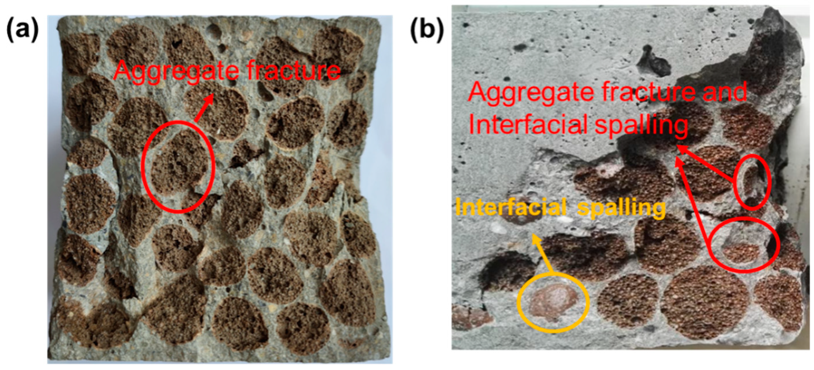
2.1. Experimental Basis of Model Establishment
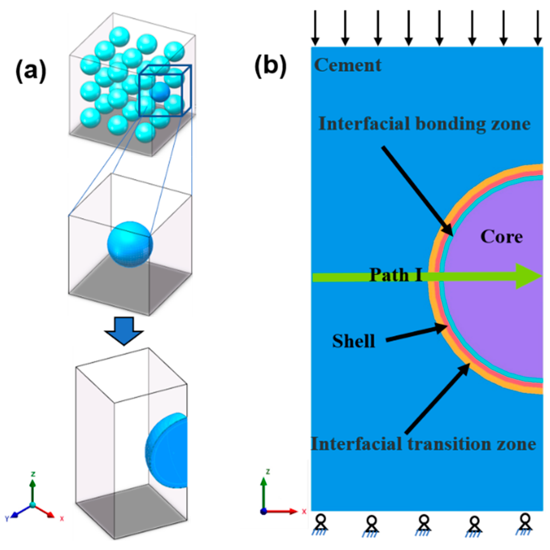
The mineral composition in the core of CSLWA was designed by using MgO–Al2O3–SiO2–CaO quaternary phase system, and a cordierite ceramsite with outstanding properties was successfully prepared. By its combination with the firing system of high belite cement, the cordierite/belite CSLWA was prepared by a single-firing process. Furthermore, in our previous study, the influence of cordierite/belite CSLWA on the mechanical properties and fracture behavior of LWAC was investigated [21]. The results showed that both the strength of the aggregate and ITZ properties significantly affected the failure mode of LWAC [16,18]. The possible failure morphology is shown in Figure 1b. In contrast with the failure morphology of ordinary LWAC shown in Figure 1a, interfacial spalling failure is observed in the CSLWA in addition to aggregate fracture. A comprehensive analysis of the failure morphology indicates that the fracture behavior of LWAC is related not only to the strength of LWA, but also to the mechanical properties of ITZ. Therefore, it is necessary to establish a three-dimensional (3D) unit-cell model to discuss the influence of the aggregate strength and ITZ mechanical properties on the failure modes of LWAC.

2.2. Methodology

Herein, a simplified 3D unit cell, composed of the cement matrix, spherical LWA, ITZ, and IBZ was built to represent CSLWA, as shown in Figure 2a. The core–shell structure in CSLWA was idealized into a core with the radius of 4.5 mm and the surrounding shell with the thickness of 0.5 mm. The dimensions of the unit-cell are 20 mm × 20 mm × 20 mm. During the FE analysis, one quarter of the unit-cell was used to take advantage of symmetry, as shown in Figure 2b. Ten-node quadratic tetrahedral elements (SOLID187) were employed to discretize the micro model. The embedded method was adopted to simulate the bond between the lightweight aggregate and the cement matrix, assuming a perfect bond between them. Due to the presence of interfaces, the mesh in the IBZ and ITZ regions were sufficiently refined to resolve local high-strain gradients. Finally, reasonable mesh densities were determined after repeated trials, accounting for both the solution convergence and run time. The final micro model involved 881,566 mesh elements and 1,193,817 nodes. Restraints were introduced at the bottom edges of the specimens in the direction of the applied load. Figure 2b presents details regarding the geometry and the boundary conditions of the specimens that were used for the simulations. The micro model was analyzed using static structural analysis in ANSYS/workbench. In the static analysis, displacement was applied at the top of the model. The prescribed boundary conditions are defined as follows [24]:
u z = 0   on   z = 0 ; u z = n × L   on   z = 0
where uz is the displacement component along the z-direction, n denotes the specified displacement coefficient, which may be considered as 0.25%, and L is the side length of the model.
It is important to mention that in the comparative analysis, equivalent stress was employed as the stress measure in this study. Unless otherwise specified, stress refers to equivalent stress in the following context.

2.3. Material Parameters

In all the models, the core is made of porous ceramsite with a porosity of about 50%, and its skeleton crystal minerals mainly include cordierite and anorthite. Material parameters of various minerals can be found through experiments and literature studies [26], and the corresponding results are presented in Table 1. The upper and lower bounds of the effective elastic parameters of the core can be predicted by using the Voigt model and Reuss model, for which the analytical formulas are represented as follows:
E c = E 1 V 1 + E 2 V 2
E c = E 1 E 2 E 1 V 2 + E 2 V 1
E = E c ( 1 1.9 P + 0.9 P 2 )
where E is the calculated effective elastic modulus of the composite material; E1 and E2 are the elastic moduli of cordierite and belite, respectively; V1 and V2 are their corresponding volume fractions; and P denotes the porosity of LWA.
The shell of CSLWA consists of a belite cement clinker, for which the continuous hydration helps to improve the “micro-bleeding” and “wall effect” around the aggregate. They provide a dense microstructure and high bond strength of ITZ between CSLWA and cement paste [21,27]. Furthermore, in the Powers’ model [28], cement matrix is mainly abstracted into three parts, involving in-cement hydration products, incomplete hydrated cement particles and gel pores. Therefore, through the use of the Powers’ model, we can calculate the volume fraction of each component in the cement matrix based on the initial water cement ratio and hydration degree. Furthermore, the Mori-Tanaka theory holds that the average stress in the cement matrix is uniform throughout the material and independent of the position of the domain where the average treatment is carried out [29]. In a cement matrix, cement hydration products are regarded as part of the matrix, while incomplete hydrated cement particles and gel pores are regarded as inclusion and equivalent media respectively. Therefore, the Mori-Tanaka theory can be used to predict the mechanical properties of cement matrix with different hydration ages.
With reference to the literature [30], the elastic parameters of the hydration products and incomplete hydrated cement particles are presented in Table 1. The hydration products of belite cement clinker resemble those of ordinary cement, thus the elastic modulus and Poisson’s ratio of a belite shell at different ages can be predicted by adopting the Powers’ model.

3. Results and Discussion

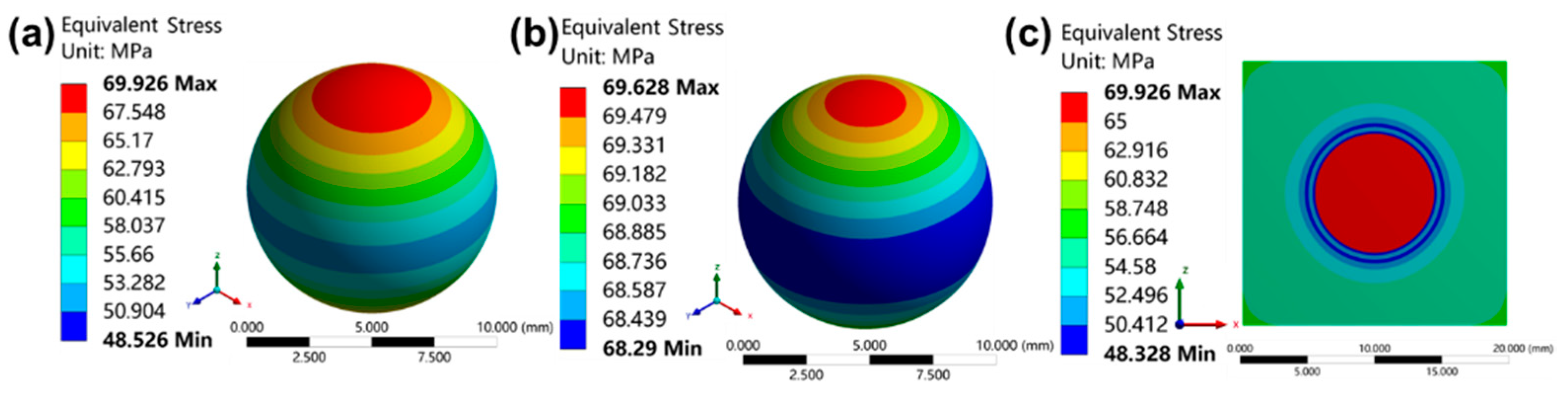
3.1. Influences of Characteristics of CSLWA on Stress Distribution in Microregion of LWAC

The mechanical properties of LWAs are important factors affecting the damage modes of LWAC. However, the mineral composition of core, core–shell thickness ratio, and the properties of the core–shell IBZ significantly affect the mechanical properties of CSLWA. In this section, the influence of the core mineral composition, core–shell thickness ratio, and core–shell IBZ on the stress distribution of the LWAC microregion are investigated, and the relationship between the characteristics of CSLWA and the failure behavior of LWAC are clarified.

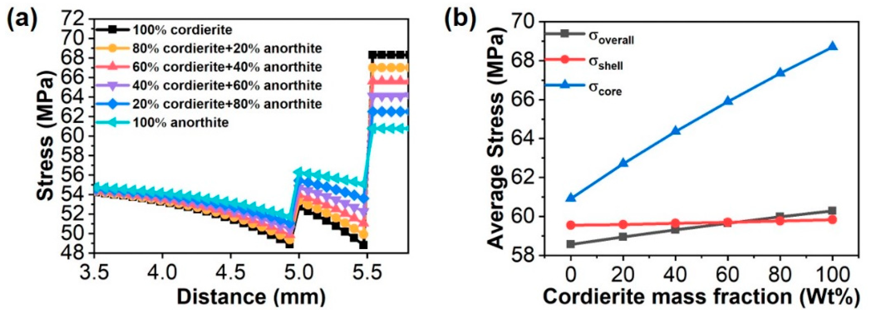
3.1.1. Components of the Core

The use of different sintering systems leads to a variation in the components of the core of CSLWA. Therefore, an exploration of the influences of the core components on the mechanical properties of the LWAC is highly important. Based on this, a series of parametric experiments on different components was performed, and the core elastic parameters of different cordierite contents were estimated through Equations (1)–(3), for which the corresponding results are presented in Table 2. The contour diagrams of stress (equivalent) distributions in the microregion of the core–shell structure LWAC are shown in Figure 3. It is clear that the maximum stress appears at both ends of the LWA, and that the minimum equivalent stress appears at the middle position along the z-direction. The minimum stress level on the shell is significantly lower than that on the core surface.
Moreover, Figure 3a shows the stress distribution curves of CSLWA with different cordierite contents along the PATH I, for which an abscissa of 5 and 5.5 mm, respectively, represents the interface between the shell and cement matrix and the interface between the core and shell. The stress distribution contours shown in Figure 3 and the stress distribution curves exhibited in Figure 4a, indicate that the core of CSLWA carries most of the stress, and with the increase in the cordierite content, the stress difference at the interface between the core/shell gradually increases, and the overall average stress of the model increases. Figure 4b shows the variation curve of the average stress in each part of the model, revealing that with the increase in the cordierite content in the core, the average stress in the core increases more sharply than the average stress in the shell. This indicates that an increase in the content of the high modulus components can intensify the stress concentration between cores and shells, thus increasing the possibility of microcrack initiation and of growth at the interface between the core and shell of LWAC. It was also found that the greater the difference between elastic modulus of aggregate and cement matrix, the greater the transverse tensile stress, and the more severe the stress concentration [31], which is consistent with the above-mentioned calculated stress distribution.

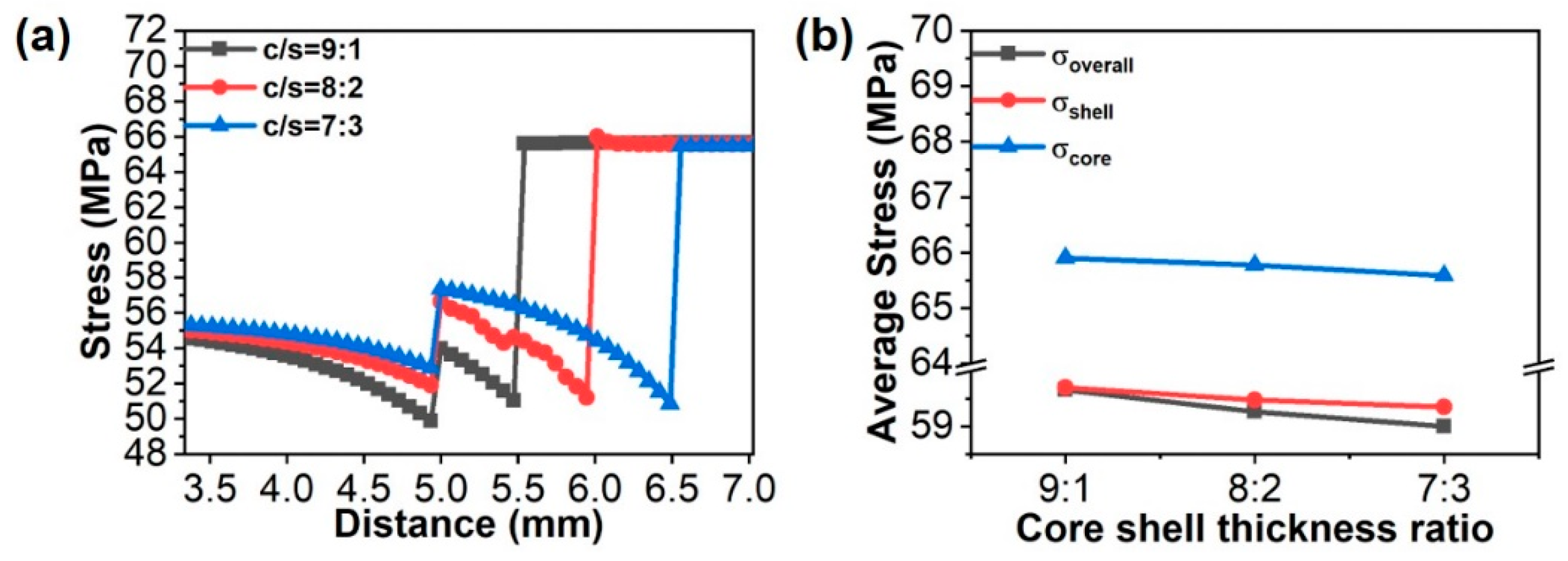
3.1.2. Core–Shell Thickness Ratio

The thickness ratio of core to shell is a key factor that affects not only the hydration process of CSLWA, but also the mechanical properties of CSLWA. In this section, 60% cordierite + 40% anorthite was kept fixed for the core; however, the thickness ratio C/S was varied, in relation to the following different values: 9:1, 8:2, and 7:3. Figure 5a shows the curves of stress distribution of core–shell LWAC with different thickness ratios along PATH I. The figure illustrates that, with the increase in the core–shell thickness ratio, the minimum stress value on the path changes location from the shell/cement matrix interface to the core/shell interface, and the stress difference on-shell also increases. A further analysis of the average stress of each part of the model, shown in Figure 5b, indicates that the overall average stress of the model decreases slightly with an increase in the core–shell thickness ratio, whereas the stress on the core and shell almost remains unaltered. In other words, the core–shell thickness ratio does not affect the overall mechanical properties of the core–shell structure LWAC. However, an analysis of the stress distribution curves indicates that the increase in the core–shell thickness ratio leads to an increase in the stress difference on both sides of the shell, which increases the possibility of nucleation of microcracks on the shell. Therefore, given that the shell is completely hydrated, reducing the core–shell thickness ratio of the CSLWA can lead to a more uniform stress distribution of LWAC.

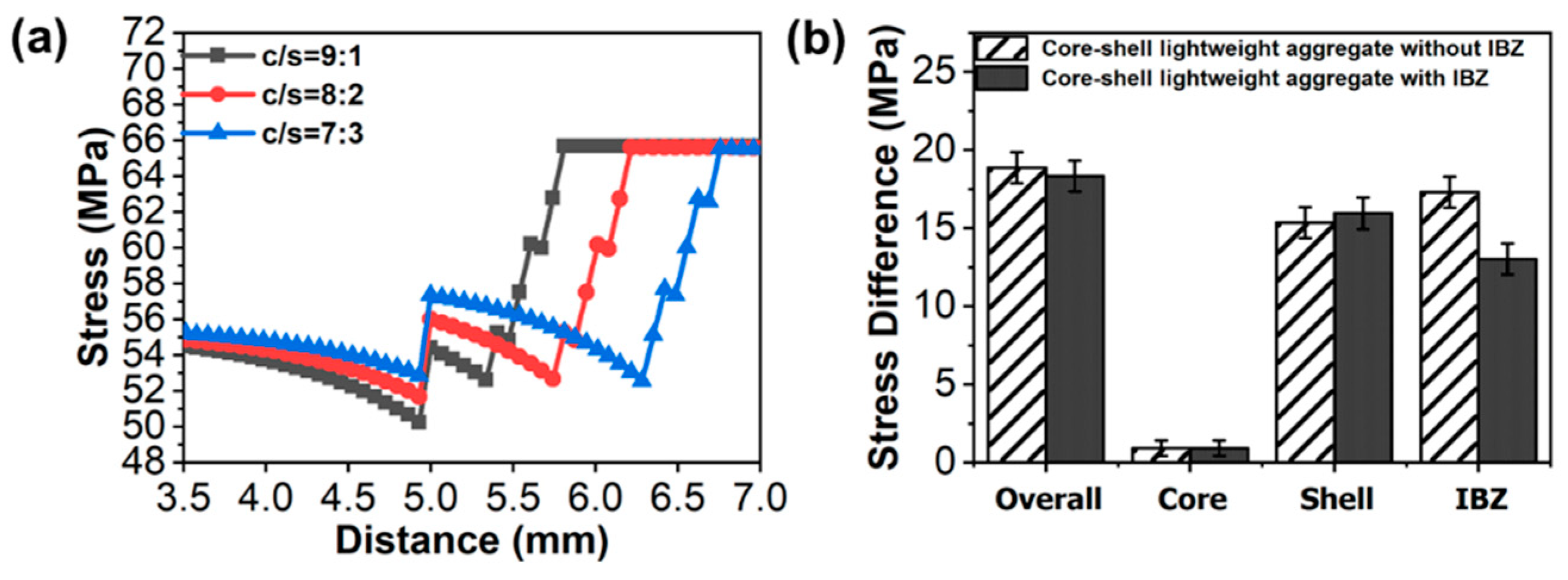
3.1.3. Core–Shell Interfacial Bonding Zone

During the process of sintering at high temperatures, chemical species in the cordierite/ceramsite core and the belite shell diffuse to the other side, due to the difference in atomic concentration This facilitates the formation of an IBZ between the core and the shell. Therefore, a study of the influence of IBZ on the stress distribution in the microregion of LWAC can help to develop understanding on the preparation process of CSLWA. Figure 6a shows the stress distribution curves along PATH I for different core–shell thickness ratios after the introduction of IBZ. A comparative analysis of the stress distribution curves shown in Figure 5a indicates that the IBZ alleviates the stress difference at the core–shell interface, and this effect becomes more apparent with an increase in the core–shell thickness ratio. Figure 6b illustrates that, compared to the model without IBZ, the stress difference at the core–shell interface decreases by about 20%. Furthermore, the overall stress difference of the model is slightly reduced, which indicates that the incorporation of IBZ can regulate stress distribution in the core–shell structure LWAC, in particular, at the interface between the core and the shell.

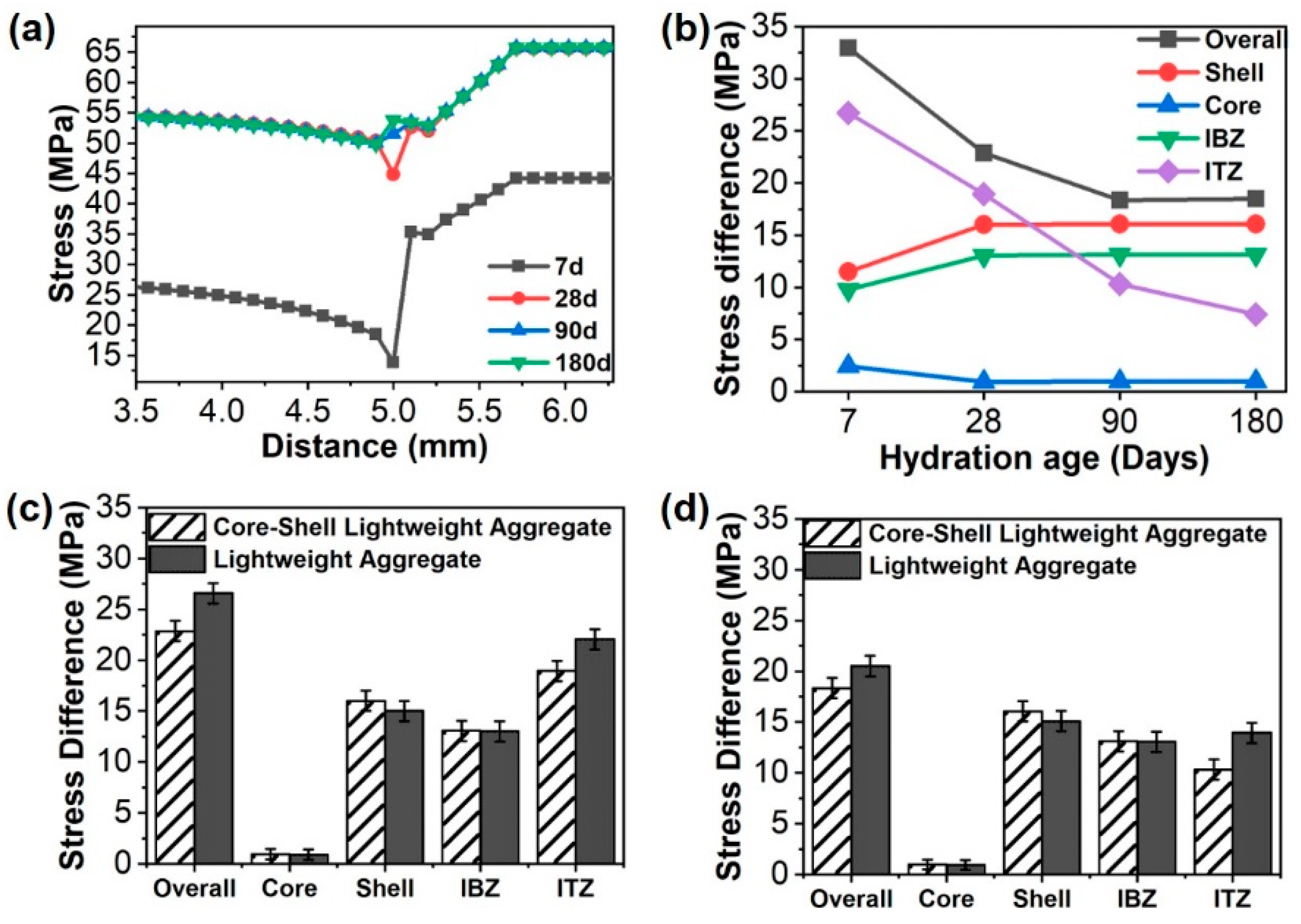
3.2. Influences of ITZ Properties on Stress Distribution in Microregion of LWAC

3.2.1. Equivalent Treatment of ITZ

The ITZ surrounding the aggregates has a negligible thickness; therefore, it is difficult to take ITZs into account explicitly in the modeling of LWAC. For this reason, an effective mixing interface was defined around each aggregate, which was formed by the ITZ and a volume fraction of the bulk cement paste [32]. In this equivalent method, the volume fraction of the residual clinkers and formed hydrates was calculated in the microregion close to the aggregate according to the local hydration kinetics. Then, the properties of the effective mixed interphase were found to be identical to the effective properties of the ITZs. The homogenization method primarily considers the porosity and adhesion performance of the ITZ at different hydration ages, generally reflecting the main properties of the ITZ.

3.2.2. Variation of Microregion Stress Distribution

The ITZ, in most cases, is the weakest zone in concrete due to its high porosity and weak mechanical properties. Under external forces, microcracks first initiate and coalesce in this area, which then promotes the macroscopic cracking of concrete [25]. However, the continuous hydration of the belite shell with CSLWA can effectively improve the performance of ITZ and enhance the structural integrity. In this study, the elastic modulus and Poisson’s ratio of the belite shell and a cement matrix with different hydration ages were predicted using the Mori–Tanaka method [29]. The calculation results are presented in Table 3. First, the relationship between the varying properties of ITZ and the microregion stress distribution of the core–shell structure LWAC, with different hydration, ages were mainly studied. The results are shown in Figure 7a,b. The results indicate that with the increase in the hydration duration, the curve of stress distribution on PATH I turns smooth, and the stress difference in ITZ decreases dramatically. Moreover, the stress difference in each part of the model decreases gradually until they reach a plateau. It shows that, with the increase in hydration age, the stress distribution in the microregion of LWAC ultimately becomes more uniform. Furthermore, the hydration of belite shells provides a dense microstructure and leads to the high bond strength of ITZ [21], which is in accordance with the simulation results obtained in this study. Furthermore, these results were compared with those of ordinary LWAC under the same hydration age as shown in Figure 7c,d. It has been found that the microregion stress difference in the ITZ of core–shell structure LWAC is less than that of ordinary LWAC. Therefore, it can be concluded that the CSLWA can improve the mechanical properties of the ITZ through the continuous hydration of the shell and that it can alleviate the stress concentration phenomenon at the interface between the aggregate and cement matrix. Therefore, CSLWA indirectly improves the overall mechanical properties of LWAC.

4. Conclusions

In this study, the stress distribution in the microregion close to the shell of core–shell structure LWAC was studied using finite element analysis. The main conclusions drawn from this study are as follows:
(1)
The mineral composition of the core significantly influences the stress distribution in the microregion close to the shell of core–shell structure LWAC. Under the condition of constant porosity, when the content of high-modulus components increases, the minimum stress location in the model is gradually transferred from the core–shell interface to the interface between the shell and cement matrix. Moreover, the stress difference between the core and shell is intensified, which increases the possibility of nucleation and the propagation of microcracks at the interface.
(2)
The core–shell thickness ratio primarily affects CSLWA stress distribution on the shell. With the increase of core–shell thickness ratio, the stress difference on the shell increases, and the more uneven stress distribution likely leads to the nucleation and extension of microcracks on the shell. Furthermore, IBZ can reduce the stress difference of the core–shell interface and can delay the local failure in LWAC.
(3)
Compared to the ordinary LWAC of the same grade, the stress distribution in the microregion close to the shell of the core–shell structure LWAC is more uniform. Moreover, an increase in the hydration age generates similar effects. These findings demonstrate that the CSLWA acts as a potential candidate to improve the failure resistance of LWAC.

Author Contributions

Conceptualization, M.Z., L.Z. and W.X.; methodology, M.Z., L.Z. and H.Z.; software, M.Z. and W.W. validation, W.W. and W.X.; formal analysis, M.Z.; investigation, L.Z. and H.Z.; resources, L.Z.; data curation, W.X.; writing—original draft preparation, M.Z.; writing—review and editing, M.Z. and H.Z.; visualization, M.Z., L.Z. and H.Z.; supervision, L.Z. and H.Z.; project administration, L.Z.; funding acquisition, L.Z. All authors have read and agreed to the published version of the manuscript.

Funding

This research was funded by National Natural Science Foundation of China (Grant Nos. 51808464 and 51978590).

Institutional Review Board Statement

Not applicable.

Informed Consent Statement

Not applicable.

Data Availability Statement

Not applicable.

Conflicts of Interest

The authors declare that they have no known competing financial interests or personal relationships that could have appeared to influence the work reported in this paper.

References

  1. Korolev, E.V.; Inozemtcev, A.S. Preparation and research of the high-Strength lightweight concrete based on hollow microspheres. Adv. Mater. Res. 2013, 746, 285–288. [Google Scholar] [CrossRef]
  2. Mo, K.H.; Goh, S.H.; Alengaram, U.J.; Visintin, P.; Jumaat, M.Z. Mechanical, toughness, bond and durability-related properties of lightweight concrete reinforced with steel fibres. Mater. Struct. 2017, 50, 1–14. [Google Scholar] [CrossRef]
  3. Al-Khaiat, H.; Haque, M.N. Effect of initial curing on early strength and physical properties of a lightweight concrete. Cem. Concr. Res. 1998, 28, 859–866. [Google Scholar]
  4. Fang, C.Q.; Yi, M.Y. Seismic Performance of a Reinforced Lightweight Aggregate Concrete Frame. Key Eng. Mater. 2007, 340–341, 1139–1144. [Google Scholar] [CrossRef]
  5. Hwang, C.-L.; Hung, M.-F. Durability design and performance of self-consolidating lightweight concrete. Constr. Build. Mater. 2005, 19, 619–626. [Google Scholar] [CrossRef]
  6. Hossain, K.M.A.; Ahmed, S.; Lachemi, M. Lightweight concrete incorporating pumice based blended cement and aggregate: Mechanical and durability characteristics. Constr. Build. Mater. 2011, 25, 1186–1195. [Google Scholar] [CrossRef]
  7. Libre, N.A.; Shekarchi, M.; Mahoutian, M.; Soroushian, P. Mechanical properties of hybrid fiber reinforced lightweight aggregate concrete made with natural pumice. Constr. Build. Mater. 2011, 25, 2458–2464. [Google Scholar] [CrossRef]
  8. Lv, J.; Zhou, T.; Du, Q.; Wu, H. Effects of rubber particles on mechanical properties of lightweight aggregate concrete. Constr. Build. Mater. 2015, 91, 145–149. [Google Scholar] [CrossRef]
  9. Li, J.; Huang, J.; Niu, J.; Wan, C. Mesoscopic study on axial compressive damage of steel fiber reinforced lightweight aggregate concrete. Constr. Build. Mater. 2019, 196, 14–25. [Google Scholar] [CrossRef]
  10. Hassanpour, M.; Shafigh, P.; Mahmud, H.B. Lightweight aggregate concrete fiber reinforcement—A review. Constr. Build. Mater. 2012, 37, 452–461. [Google Scholar] [CrossRef]
  11. He, Y.; Zhang, X.; Zhang, Y.; Zhou, Y. Effects of particle characteristics of lightweight aggregate on mechanical properties of lightweight aggregate concrete. Constr. Build. Mater. 2014, 72, 270–282. [Google Scholar] [CrossRef]
  12. Cui, H.Z.; Lo, T.Y.; Memon, S.A.; Xing, F.; Shi, X. Analytical model for compressive strength, elastic modulus and peak strain of structural lightweight aggregate concrete. Constr. Build. Mater. 2012, 36, 1036–1043. [Google Scholar] [CrossRef]
  13. Ke, Y.; Ortola, S.; Beaucour, A.L.; Dumontet, H. Identification of microstructural characteristics in lightweight aggregate concretes by micromechanical modelling including the interfacial transition zone (ITZ). Cem. Concr. Res. 2010, 40, 1590–1600. [Google Scholar] [CrossRef]
  14. Bentz, D.P. Influence of internal curing using lightweight aggregates on interfacial transition zone percolation and chloride ingress in mortars. Cem. Concr. Compos. 2009, 31, 285–289. [Google Scholar] [CrossRef]
  15. Kuroda, M.; Watanabe, T.; Terashi, N. Increase of bond strength at interfacial transition zone by the use of fly ash. Cem. Concr. Res. 2000, 30, 253–258. [Google Scholar] [CrossRef]
  16. Cui, H.Z.; Lo, T.Y.; Memon, S.A.; Xu, W. Effect of lightweight aggregates on the mechanical properties and brittleness of lightweight aggregate concrete. Constr. Build. Mater. 2012, 35, 149–158. [Google Scholar] [CrossRef]
  17. Lyu, K.; Garboczi, E.J.; She, W.; Miao, C. The effect of rough vs. smooth aggregate surfaces on the characteristics of the interfacial transition zone. Cem. Concr. Compos. 2019, 99, 49–61. [Google Scholar] [CrossRef]
  18. Yew, M.K.; Mahmud, H.B.; Shafigh, P.; Ang, B.C.; Yew, M.C. Effects of polypropylene twisted bundle fibers on the mechanical properties of high-strength oil palm shell lightweight concrete. Mater. Struct. 2015, 49, 1221–1233. [Google Scholar] [CrossRef]
  19. Hu, S.; Yang, T.; Wang, F.; Wang, J. Preparation and design of function aggregate in concrete. Mater. Sci. Forum 2010, 650, 17–22. [Google Scholar] [CrossRef]
  20. Liu, C.; Liu, L.; Tan, K.; Zhang, L.; Tang, K.; Shi, X. Fabrication and characterization of porous cordierite ceramics prepared from ferrochromium slag. Ceram. Int. 2016, 42, 734–742. [Google Scholar] [CrossRef]
  21. Zhang, L.; Zhang, Y.; Liu, C.; Liu, L.; Tang, K. Study on microstructure and bond strength of interfacial transition zone between cement paste and high-performance lightweight aggregates prepared from ferrochromium slag. Constr. Build. Mater. 2017, 142, 31–41. [Google Scholar] [CrossRef]
  22. Sahoo, S.; Selvaraju, A.K.; Suriya Prakash, S. Mechanical characterization of structural lightweight aggregate concrete made with sintered fly ash aggregates and synthetic fibres. Cem. Concr. Compos. 2020, 113, 1–16. [Google Scholar] [CrossRef]
  23. Bonifácio, A.L.; Mendes, J.C.; Farage, M.C.R.; Barbosa, F.d.S.; Beaucour, A.-L. Predicting the mechanical properties of lightweight aggregate concrete using finite element method. Rev. IBRACON Estrut. Mater. 2020, 13, e13410. [Google Scholar] [CrossRef]
  24. Ding, H.; Jia, H.; Li, M.; Miao, W.; Li, C.; Liu, Q. Study on stress distribution in microregion close to the shell of core-shell particle reinforced metal matrix composites. Mater. Sci. Eng. A 2020, 784, 139317. [Google Scholar] [CrossRef]
  25. Ollivier, J.P.; Maso, J.C.; Bourdette, B. Interfacial transition zone in concrete. Adv. Cem. Based Mater. 1996, 2, 30–38. [Google Scholar] [CrossRef]
  26. Zadeh Hayati, E.; Mohammad Moradi, O.; Ghassemi Kakroudi, M. Investigation the effect of sintering temperature on Young’s modulus evaluation and thermal shock behavior of a cordierite–mullite based composite. Mater. Des. 2013, 45, 571–575. [Google Scholar] [CrossRef]
  27. Grondin, F.; Matallah, M. How to consider the interfacial transition zones in the finite element modelling of concrete? Cem. Concr. Res. 2014, 58, 67–75. [Google Scholar] [CrossRef] [Green Version]
  28. Königsberger, M.; Hellmich, C.; Pichler, B. Densification of C-S-H is mainly driven by available precipitation space, as quantified through an analytical cement hydration model based on NMR data. Cem. Concr. Res. 2016, 88, 170–183. [Google Scholar] [CrossRef]
  29. Mori, T.; Tanaka, K. Average stress in matrix and average elastic energy of materials with misfitting inclusions. Acta Metall. 1973, 21, 571–574. [Google Scholar] [CrossRef]
  30. S˘milauer, V.; Bittnar, Z.K. Microstructure-based micromechanical prediction of elastic properties in hydrating cement paste. Cem. Concr. Res. 2006, 36, 1708–1718. [Google Scholar] [CrossRef]
  31. Wu, K.-R.; Bing, C.H.E.N.; Wu, Y.A.O.; Zhang, D. Effect of coarse aggregate type on mechanical properties of high-performance concrete. Cem. Concr. Res. 2001, 31, 1421–1425. [Google Scholar] [CrossRef]
  32. Ren, Q.; Li, Q.; Yin, Y. Concrete meso-structure characteristics and mechanical property research with numerical methods. Constr. Build. Mater. 2018, 158, 189–197. [Google Scholar] [CrossRef]
Figure 1. Failure morphology (a) Ordinary lightweight aggregate concrete and (b) Core–shell lightweight aggregate concrete.
Buildings 11 00540 g001
Figure 2. (a) Unit-cell model of core–shell lightweight aggregate concrete and (b) Schematic showing the model used in this study.
Buildings 11 00540 g002
Figure 3. Contour diagrams of stress distributions in various parts of core–shell structure LWAC: (a) Shell; (b) Core; and (c) PATH I section.
Buildings 11 00540 g003
Figure 4. (a) Path I stress distribution curves for different mineral compositions; and (b) Average stress of the core, shell, with the entire model composed of different minerals.
Buildings 11 00540 g004
Figure 5. (a) Path I stress distribution curve with different core–shell thickness ratios; and (b) Average stress of the core, shell, and the entire model with different core–shell thickness ratios.
Buildings 11 00540 g005
Figure 6. (a) Stress distribution curves of PATH I with different core–shell thickness ratios in the presence of bonding zone; and (b) Influence of core–shell interface bonding zone on stress difference of each part of the model.
Buildings 11 00540 g006
Figure 7. (a) Path I path stress distribution curve for different ages; (b) Average stress of the core, shell, and the entire model of different ages; (c) Stress difference of each part of the model at hydration age of 28 days; and (d) Stress difference of each part of the model at hydration age of 90 days.
Buildings 11 00540 g007
Table 1. Material parameters of different minerals.
Density (g cm−3)Young’s Modulus (GPa)Poisson’s Ratio
Cordierite2.30125.00.26
Anorthite2.7799.10.30
Unhydrated Particles 1350.27
Hydration Products 25.00.20
Table 2. Core elastic parameters of different cordierite contents.
Cordierite Content (wt.%)100806040200
Young’s modulus (GPa)34.37533.02431.64230.22428.76327.253
Poisson’s ratio0.260.270.270.280.290.3
Performance density (kg m−3)2.3002.3812.4672.5612.6612.770
Table 3. Material parameters of shell and cement matrix at different hydration ages (W/C = 0.5).
Hydration Age (Days)72890180
Cement MatrixYoung’s modulus (GPa)11.20022.30022.30022.300
Poisson’s ratio0.330.250.250.25
Belite ShellYoung’s modulus (GPa)23.65523.68223.96523.964
Poisson’s ratio0.230.210.200.20
ITZ of CSLWAYoung’s modulus (GPa)8.960 20.070 23.415 24.530
Poisson’s ratio0.264 0.28 0.2800.30
ITZ of ordinary light aggregateYoung’s modulus (GPa)8.76518.34921.40822.541
Poisson’s ratio0.264 0.28 0.28 0.30
Publisher’s Note: MDPI stays neutral with regard to jurisdictional claims in published maps and institutional affiliations.

