
Assessment of Timber Roof Structures before and after Earthquakes


Civil Engineering, Structural Department, University of Zagreb, 10000 Zagreb, Croatia
*
Author to whom correspondence should be addressed.
Buildings 2021, 11(11), 528; https://doi.org/10.3390/buildings11110528
Submission received: 6 October 2021
/
Revised: 4 November 2021
/
Accepted: 8 November 2021
/
Published: 10 November 2021
Abstract
:The global objective of sustainable development has been greatly directed toward the preservation of existing structures. Therefore, condition assessment and reconstruction of existing timber structures have been gaining importance in recent times. This is particularly evident on timber roofs whose elements are exposed to degradation, either because of rheological effects or due to the direct influence of moisture and biological factors. In case of accidental events, such as an earthquake, the question of the structure’s condition is essential for the condition of the entire building. In order to prove the load-bearing capacity and serviceability of existing structures, as well as to check the need for reconstruction, it is necessary to define crucial parameters that are influencing the condition of materials, elements, and systems. Although there are many non destructive testing methods, the frequency and scope of their use, as well as the decision-making approach, have not been defined. In the paper, non-destructive and semi-destructive methods frequently used for timber structures are explained. A systematic review of criteria to be used in the assessment of load-bearing timber structures in a seismic active area was the main objective of this paper as well as the illustration of non-destructive and semi-destructive test methods through a case study involving roof construction of a hundred-year-old building in Zagreb, Croatia. Pre- and post-earthquake inspection was made. The overall condition of the roof structure after two significant earthquakes can be assessed as satisfactory given that the observed system is a large-span and massive roof structure. The presented results and identification of typical damages after the earthquake are presented in order to facilitate policy makers and for the future implementation of development strategies in the renovation of the city.
1. Introduction
European building stock comprises a large number of masonry structures with timber roofs and floors. These kinds of structures often give the recognizable identity of old European cities but are vulnerable to seismic excitation. Therefore, the knowledge of their current state and possible structural upgrading is beneficial. In this regard, the continuous assessment and monitoring of the seismic safety and vulnerability of buildings must be obtained on the highest level and with state-of-the-art principles [1,2,3].
In 2020, Croatia was hit by two devastating earthquakes. The first earthquake occurred on 22 March 2020, with the epicenter 10 km from Zagreb and a magnitude of ML = 5.5. The second one appeared on 30 December 2020, with the epicenter near the town of Petrinja, which is about 50 km from Zagreb. The magnitude was ML = 6.3. The magnitudes are shown in Figure 1. World Bank estimates the total financial damage from the Zagreb earthquake as EUR 11.3 billion and EUR 5.1–5.5 billion for the Petrinja earthquake [4]. About 26,000 buildings were damaged in the first earthquake and more than 47,000 in the second.
The city of Zagreb has moderate seismic hazard (expected peak ground acceleration in the return period of 475 years is ag = 0.25–0.28), but it is highly exposed, and city blocks in the historical downtown were built approx. 100 years ago. It must be said that many buildings experience a lack of maintenance and were subjected to numerous modifications and reconstructions [5]. Preparedness and awareness for earthquakes in Zagreb (and in Croatia) are quite limited due to the low frequency of earthquakes. The last devastating earthquake hit Zagreb 130 years ago. A vast majority of citizens were surprised by the devastating effects of the earthquake(s) and the consequences they will have to face soon.
Cities in continental Croatia were built on the legacy and principles of construction in Austro-Hungary from the beginning of the 20th century. Most historical urban city cores were built before modern seismic codes, and buildings were not designed as earthquake-resistant structures. After the Skopje earthquake in 1963, the norms developed and building styles changed, and various materials were used to build new structures. Before implementing the seismic norms, a combination of masonry and wood was most often used as building material. The walls were masonry, and the mezzanine and roof structures were wooden. Such facilities suffered the most in the mentioned earthquakes [6]. After 1964, masonry buildings were systematically built with horizontal and vertical confining elements and concrete started to prevail as a load-bearing material in structures.
The standard building in the center of Zagreb has a basement, ground floor, and three additional floors. The Petrinja earthquake damaged the towns Petrinja, Sisak and Glina, and the surrounding villages. The construction style in these towns is similar to the center of Zagreb, but the number of floors is smaller. In the villages around the mentioned towns, family houses were built without vertical and horizontal confining elements, and such buildings were largely destroyed.
Immediate actions and rapid post-earthquake methodology after the Zagreb earthquake are explained by Uroš et al. [7]. Damage classification of the residential masonry buildings with relevant data about the history of construction in Zagreb, earthquake magnitudes and epicenter, and typical failures are explained by Stepinac et al. [6].
As masonry buildings are the most sensitive to the effects of earthquakes, it is precisely such buildings that have suffered the most in recent earthquakes. A large number of such buildings has not been adequately maintained, and such facilities have been significantly damaged. Many buildings in Zagreb have been under energy renovation processes but without any structural or seismic reinforcement. As the mezzanine constructions are mostly wooden, the constructions have a lack of the box effect—they are weak to take on horizontal actions [8,9]. However, the idea of this paper is not to focus on masonry structures but timber structures, i.e., on parts of structures made of timber. It is common knowledge that wood is a suitable material for construction in earthquake-prone areas, but still, criteria for seismic vulnerability assessment are needed [10]. In transition countries, wood has not been considerably used as it is considered an inefficient and not durable product. This problem has been exposed to the Croatian public many times [11,12], but due to the slightly higher cost of construction in wood and subjective (wrong) reasons, wood is insufficiently used in construction in Croatia. Recent earthquakes have revealed that no timber buildings were damaged in the earthquake, and interest in building in wood has increased. However, parts of the structural systems were damaged, especially the timber roofs of typical masonry buildings.
Seidek et al. [13] proposed a simulation-based model for the assessment and quantification of seismic resilience of communities. Due to its modularized nature, the proposed simulation model can combine two different aspects of community recovery to quantify the seismic resilience of communities: physical and social recovery. Although the proposed simulation model combines the physical aspect of community resilience (related to the buildings) and the social aspect (related to the injuries/fatalities), other critical dimensions of community resilience have been accounted for in this study. For example, bridge and transportation network damage can affect traffic flow and therefore access to healthcare facilities. Lifelines such as power, gas, and water systems can also profoundly influence resilience and the recovery trajectory.
In research by Vona et al. [14], a model that allows a first attempt in the probabilistic quantification of resilience communities based on the housing system was described and proposed. At the beginning of this study, some considerations and evaluations about the real resilience of communities based on recent studies, projects, literature, observations were reported, and a modified model of community resilience was defined. For each building type, RI is defined based on convolution between the state of the damage (probability of occurrence) for a specific seismic intensity, corresponding expected ratio cost, and expected ratio time. Thus, the model is based on a numerical and probabilistic evaluation of the performance of buildings, repair cost and repair time.
This paper presents the typology of timber roofs in Croatia and the damage caused by recent earthquakes. The focus of the work is on the pre-earthquake and post-earthquake assessment of a typical timber roof system on the typical masonry building in the city center of Zagreb. The mentioned methodology is shown in a case study. The roof structure of the case study was inspected in detail before the earthquake, and basic guidelines for further use were given. After the earthquakes in Zagreb and Petrinja, the object was inspected again, and the damage from the earthquake was recorded. The paper contributes to the:
- global knowledge of the different assessment phases and procedures in the classical structural assessment and post-earthquake assessment of timber structures (the methodology has been supplemented);
- the knowledge on roof systems in Zagreb downtown (the typical roofing systems are shown by figures and basic explanations);
- damage database of timber roofs after the Zagreb earthquake (the analyzed results show vulnerability of timber roofs and damage caused by timber roofs).
- database of case studies (showing the full assessment on a case study which can help practitioners in proper condition assessments).
The presented results of damages and identification of typical damages after an earthquake should be useful for policy makers and for future implementation of development strategies in the renovation of the cities. As the roof systems in Zagreb and other historical city areas are similar, the shown case study can be of use in assessment of other damaged roof systems.
2. Timber Roof Systems and Damages after the Zagreb Earthquake
Timber roofs have been widely used for many years and were the only way to overcome the horizontal span in masonry buildings. With the beginning of the use of concrete in Croatia, roofing in wood is less common but still prevails in smaller buildings.
In this paper, the focus is placed on the distinct parts of Zagreb, where older buildings predominate, most of which are built with traditional timber roof systems. The roof structure is usually a king or queen post truss, but there are also many combined forms of timber roof structures. The basic types of traditional timber roof systems in Zagreb are shown in Figure 2. Purlins are almost always supported by brick or parapet walls. Spatial roof stabilization (bracings) is usually not executed. A small number of buildings have a concrete slab beneath the roof systems due to renovation works [6].
Two severe earthquakes hit Zagreb, the first earthquake significantly damaged many buildings, and the second, to which the epicenter was still a little further, did not cause significant structural damage. However, the second earthquake damaged (again) non-structural elements and, to a lesser extent, increased the damage on the already damaged structural elements.
The failure of non-structural elements, such as chimneys, decorative elements on facades, was detected on almost every building in the city center. The failure of gable walls, masonry columns, parts of walls between or under the windows, vaults, ceilings, staircases, etc. were common. Some of these elements also caused damage to roof systems, which often become unstable due to the collapse of individual load-bearing walls beneath them. Roof rafters and ridge beams often hit the gable walls, and in combination with their weight and amplified accelerations at the gable’s height, significant damage and failure occur. The basic damage patterns of masonry structures in historic parts of Zagreb are explained in detail by Stepinac et al. [6]. The basic failures caused by timber elements/timber roof structure are shown in Figure 3.
Post-earthquake inspections have shown that failure of chimneys had a majority impact on direct damage of roofs (Figure 4), wherein some places chimneys damaged the main load-bearing roof structure, but in most cases, broke only the rafters and the integrity of the roof was maintained (Figure 5). Almost all chimneys in the city center are made of brick, they are massive and often with a weight of more than 5 tons above the level of the top floor (attic and upwards). Chimneys, of course, were the first to be damaged, and their mass damaged the roof coverings and the roof structure itself. In the City of Zagreb, a total of more than 10,000 chimneys were damaged [15].
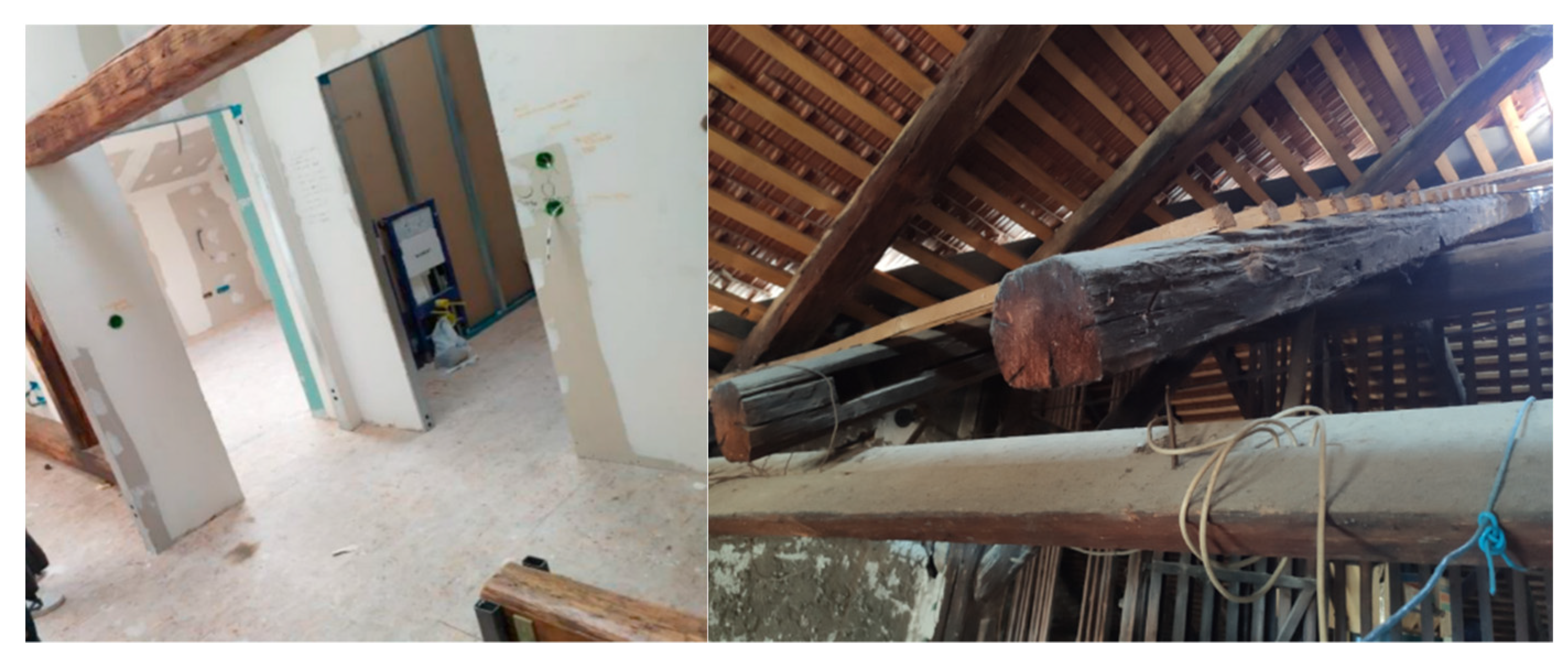
Improper design or lack of (out of plane) bracing system (Figure 6), as well as the improper design of carpentry compression joints, such as notched or Mortise and Tenon joints, without insurance in the case tensile force occurs, has caused significant damage mostly on large span roofs (Figure 7). In addition, many modifications have been made in roof structures due to the attic conversion to residential purposes and thus, the basic static system of the roof structure itself was considerably changed (Figure 8). The maintenance of the buildings, i.e., the ingress of moisture in the wooden elements, also caused damage when combined with the earthquake impact (Figure 9).
The detailed post-earthquake assessment methodology is shown in the paper by Uroš et al. [7]. In this paper, a small part of the methodology and key attributes for the post-earthquake damage assessment are shown. In collecting data, the parameters related to the roof and roof systems were the condition of the roof structure, the roof, decorative parts on the roof, and chimneys, which are integral parts of the attic and significantly affected the damage to the roofs themselves.
Damage methodology for the roof elements and roof structure was divided into five levels of damage: no damage, very small damage, moderate damage, significant damage, severe damage. Figure 10 shows the damage extent to roof coverings and timber roof structures in the historic parts of Zagreb. In Donji Grad (Lower Town), the buildings are larger by the plan than in Gornji Grad (Upper Town); thus, the static systems are different. In the Upper Town, family houses and villas predominate, and in the Lower Town, multi-apartment buildings with mostly 7 to 9 residential units are the most common buildings. The total number of heavily damaged roof systems according to the engineers’ decision was 274 in the Lower town and 189 in the Upper Town. Damage to the roof coverings in the Lower Town was observed at 598 buildings, and 516 in Upper Town, respectively.
Although experienced structural engineers and architects participated in the post-earthquake assessment, a misinterpretation of the meaning of the attributes in the roof damage assessment form was observed. In the Croatian language, the term for timber roof structure (krovište) is similar to the roof covering (krov) itself. The engineers often note the same markings for both attributes; thus, from one point of view, the data for timber roof systems are not completely reliable, but still, it shows an indication of the damage. In the quick inspection of the assessed buildings database [6], almost in 70% of the situation when the roof tiles were severely damaged, an engineer had said that the timber roof structures were also severely damaged, which was not the case. In the new post-earthquake procedures for the assessment of usability, this problem should be taken into account.
To conclude, the load-bearing parts of the roof structures have mostly remained undamaged. The most significant observed damages at the roof level are damages to the roof coverings, i.e., tiles, decorative elements, and non-structural elements. Nevertheless, the number of damages due to the collapse of other structural or non-structural parts, as well as that of improper and defective construction, occupies a percentage that is not negligible.
3. Case Study
In order to obtain the best insight into the condition of a structure before and after the earthquake, the roof the National Bureau of Statistics headquarters building was taken as an example. The building dates from the second half of the 19th century and was built in the Historicism style (Figure 11). As such, the building is qualified as a part of immovable cultural good under the label Z-1525 (historical urban complex of the city of Zagreb). The building is under the protection of the Ministry of Culture, the Directorate for the Protection of Cultural Heritage, and the City Institute for the protection of Cultural and Natural Monuments in Zagreb. During its lifetime, the building was used for various purposes.
The reason for choosing this building lies in the fact that in terms of geometry, material and method of construction, it is a typical building from the 19th century, and which is dominant in the city center. Conversely, before the earthquake, a detailed assessment was carried out on the roof structure for the project of arrangement and repurpose of the attic space. In this way, there were exhaustive data on the state before the earthquake. Finally, the roof is large (in floor plan and height), and therefore the impact of the earthquake is more significant than in some smaller roof structures, which further favors the choice of the right case study.
The building plan is of a regular shape, oriented north–south (parallel to the adjacent road) and is situated on flat terrain. It occupies a total surface area of 3045 square meters. It consists of five floors and each of them is functionally business (public) space, with the ground floor accessed by an external staircase, while an internal staircase accesses the floors of the building and the attic. The roof represents typical timber large span roof construction for buildings built in the second half of the 19th century. The vertical load-bearing elements consist of masonry (solid brick) walls, while the horizontal load-bearing elements consist of timber (supported) beams and a roof structure. The roof structure comprises 15 frames in the form of a double kingbolt whose tie beams are supported by brick or bondruk parapet walls. The load-bearing structural system is designed as a dual torsion-sensitive system. The horizontal load-bearing structure takes all gravitational loads transferred to the foundations via the vertical load-bearing structure and to the load-bearing soil via foundations. It is estimated that an additional function of the horizontal load-bearing structure is to connect the vertical load-bearing elements in such a way as to ensure the operation of the mezzanine as a flexible diaphragm during lateral actions.
The floor area of 18 × 39 m in the plan is made of timber girders at a distance of 0.8–0.9 m. The beams are made of softwood (spruce), have an average size of 20 × 28 cm, and have constant spans. On the lower side of horizontal beams, there is timber formwork with plaster on the reeds. The upper side of the beams consists of a load-bearing walking system in the form of wooden formwork on which rubble and solid brick are laid as a final layer. The formwork boards are made of softwood (spruce) and have an average thickness of 2.4 cm. The upper floor elevation above the staircase is 103 cm higher than the attic floor elevation, and from the middle, toward the southwestern part of the attic, the floor elevation is increased by 75 cm compared to the average attic floor elevation. The connecting beams are raised from the attic floor level by approximately 15 cm and directly (without sub-means) supported against the masonry walls. Spatial stabilization of the roof construction was made using transverse wind bracings in roof planes and struts in frame planes. The attic space is unheated, dry, and ventilated (better ventilation at the top of the roof and slightly weaker at the mezzanine) with a relative humidity of about 60%. The temperature varies compared to the outside by about 20%. The objective was to make a complete assessment of the timber roof structure as well as to give data for design, repair, and/or strengthening of the structure or its parts to ensure the load-bearing capacity and serviceability of the structure for another purpose—office space. In a condition assessment, it is also important to prepare a maintenance and management plan to ensure the structure’s long-term preservation and optimize the costs of repair/reconstruction [14].
4. Assessment Methods
4.1. Pre-Earthquake Inspection
The procedure of inspecting the condition of the timber part of the roof structure, as well as investigative tests, were carried out following all applicable regulations and standards. The condition of the structure was assessed based on visual inspection, insight into the measured geometry of the structure (existing condition), measuring the level of moisture content in the material (indirect method), measuring the dynamic modulus of elasticity of the material (indirect method) and defining the density of the material. Measurements were performed on average on 60% of all load-bearing elements of the same type (measured in two different characteristic local positions), with the selection of reference measuring points based on visual assessment of the condition (elements with significant degradation were selected). A sample of timber was taken from the load-bearing element which was replaced by a new one during interventional remediation.
A wide range of assessment methods for assessing the overall condition of the existing timber structure is currently available on the market [15]. These include acoustic [6], electromagnetic [16], thermal [17] and optical [18] methods, as well as mechanical techniques [19]. The first step in the assessment is to determine appropriate methods, considering factors of cost-benefit analysis, and the last is to incorporate the assessed data into models that will be used to calculate the remaining capacity or even reliability of such structures [20].
4.2. Post-Earthquake Inspection
The different actions for all stages of assessments are shown in the Figure 12. The detailed post-earthquake assessment of the buildings according to the new Croatian law include detailed visual inspection, concept of repair strategies and strengthening techniques with the diagnostic report.
Post-earthquake damage inspection of roof construction consisted of a visual inspection of structural stability, an inspection of individual elements of the load-bearing structure as well an inspection of joints. Special emphasis is placed on the inspection of geometry changes, as the main sign of instability, as well as on the condition of the supports (masonry walls) as a basis for the global safety of the roof structure. In addition, the influence of failure of secondary elements was analyzed to state the final degree of damage and deciding on the proscribed classification of the structure into one of six possible categories: usable (green label, categories U1 and U2), temporarily unusable (yellow label, categories PN1 and PN2) and non-usable (red label, categories N1 and N2). The observed case study building was evaluated as temporarily unusable (category PN2), with the need for emergency interventions, which would return the structure to its initial state.
5. Assessment Results
5.1. Pre-Earthquake Inspection
5.1.1. Visual Inspection
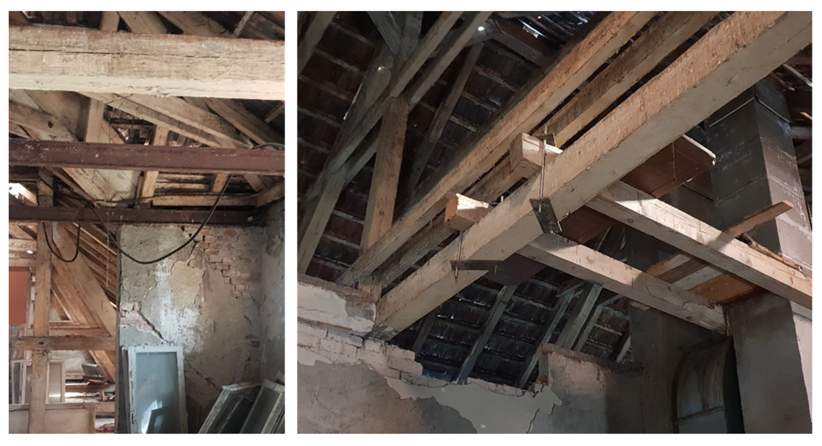
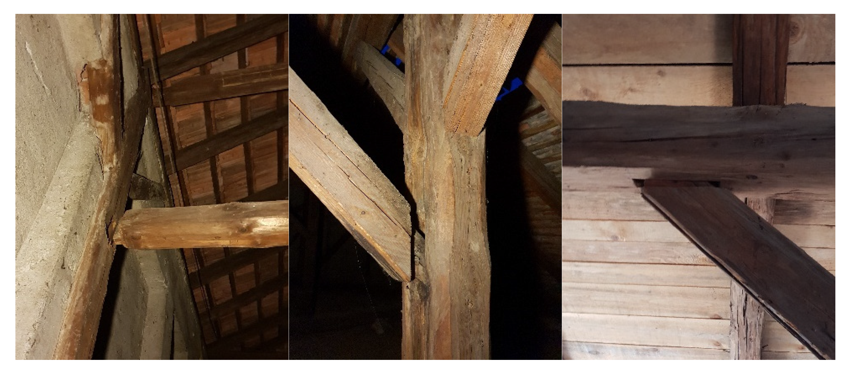
Visual inspection of all load-bearing elements of the roof structure in question was carried out following the standard HR EN 17121: 2019 [21] and the procedures given by Piazza et.al. and Dietsch et al. [19,22]. The review began with measuring the geometry of the roof and making a 3D model shown in Figure 13. On most of the roof elements, there are visible cracks, which appeared as a result of moisture change and reduction process in the wood due to drying, where the elements in POZ11-POZ30 (marked in green, Figure 14 and Figure 15) show significant load-bearing degradation, which may be a consequence not only of wood reduction but also of exceeding load-bearing capacity. A significant degradation, which has been caused by water leakage from the roof and by the appearance of decay, is visible on the elements of wall beam in POZ1, ridge beam in POZ2, rafters in POZ3 and POZ4, and valley beam and rafters in POZ5 and POZ6, ceiling joist in POZ7, and the junction of horizontal and vertical elements in POZ8 (marked in blue, Figure 14). Some elements, such as POZ5, have been strengthened or replaced in the process of emergency restoration but are still considered degraded.
The presence of insects can be noticed on the surface layers of certain roof elements. When scraping the surface of such an element after 10 to 15 mm, no further insect penetrations remain visible, which indicates that the appearance of insects was more present during the periods of cutting, sewing, or storage. It becomes clear that after the structure renovation (most likely due to smoking) the insects were destroyed.
During the inspection process, degradation of mechanical resistance and stability on the elements in POZ9 and POZ10 (marked in red, Figure 14) was noticed, and partly on other elements of the southern knee wall. Degradation is due to the loss of adhesion of the binder (mortar) at the contact of wooden elements and masonry, which is manifested by the appearance of cracks and significant spacing of the filling from the frame of the bondruk system. In addition, probes were cut in the floor structure (marked in orange, Figure 14) such that the cross-sectional dimensions and raster of the floor beams could be determined.
Investigative tests performed on visual inspection of the roof structure (Figure 15) have shown that the structure is in relatively good condition, without visible damage of biological origins (except the above-mentioned exceptions), but with a significant number of cracks. Individual (previously mentioned) structural elements cannot be considered load-bearing due to significant material degradation, excessive dimensions, or crack positions.
5.1.2. Moisture Content Measurements
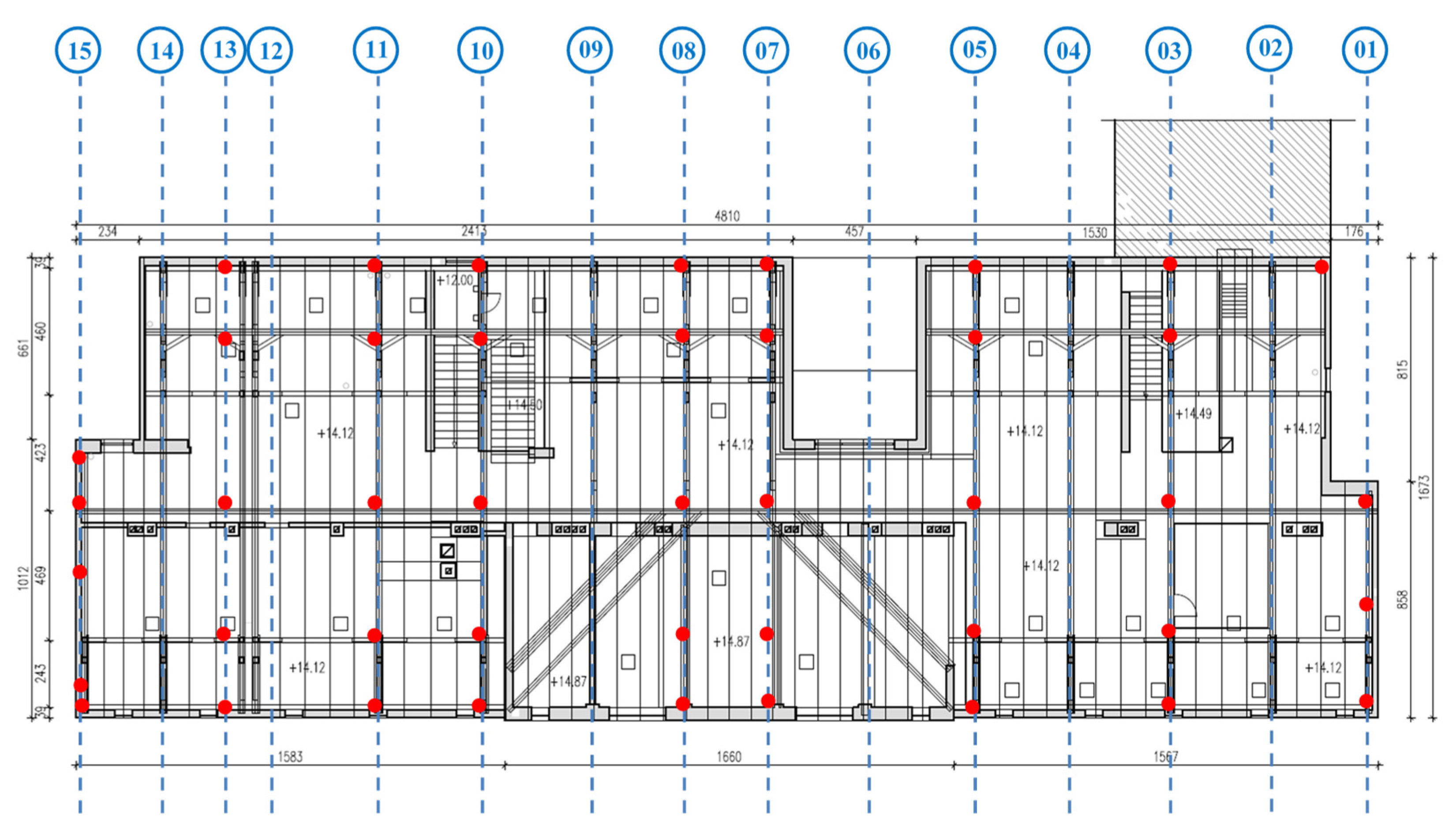
Determination of load duration class as well as service class according to HRN EN 1995-1-1: 2013 [23] is based on visual inspection of the roof structure in question and measurement of moisture content level in the material by indirect method (using hygrometer for timber structural elements) on 60% of all load-bearing elements of the same type (measured alongside supports and in the middle of the element’s span) on positions shown in Figure 16. All measurements were performed using a TROTEC Multifunction Measuring Meter T3000. Paired electrodes TS 070 60 mm Teflon insulated Electrode Tips are driven into timber elements to a depth of 60 mm with a movable piston made for precise measurement of the moisture zone and depth of moisture distribution in wood TS 70 Ram-in Electrode. The electrodes are connected over the piston to the measuring device with a cable TC 20 BNC which is required for the electrical signal transmission.
The device was calibrated using the TROTEC Calibration-Block V1 T510/T3000A device. In the measurement settings, based on a sample of wood extracted from the load-bearing element of the structure in question (rafter element), it was assumed that it was a botanical species of European (common) spruce (Picea abies).
All measurements were performed following the standard HRN EN 13183-2: 2008 [24], whereby a single measurement was performed for each measuring point. Although the device’s accuracy is to two decimal places, the results are given in one decimal place. The measurement results for individual elements are given in Table 1, where the equilibrium humidity in wood is defined in mass percentages, that is, it is given as the ratio of the difference between the mass of wet and dry wood and the mass of dry wood.
Investigative tests based on the equilibrium moisture content in wood, the amount of which varies from 9.9% to 15.6% along with the support and from 9.2% to 12.8% in the middle of the span and (depending on the position and type of structural element) concluded that the average value of equilibrium moisture of wood is 12.1% with a standard deviation of 1.275% and a coefficient of variation of 0.105.
Given that the average moisture content in almost all elements does not exceed 20%, and the moisture content of wood corresponds to a temperature of 20 °C and relative humidity of the environment that only a few weeks a year exceeds 85%, assuming that the environment will be regularly heated and ventilated, the structure may be considered to meet the requirements for service class 2.
5.1.3. Dynamic MOE Measurements
Determination of wood class according to HRN EN 338: 2016 [25] is based on visual inspection of the roof structure and measurement of the dynamic modulus of elasticity (MOE) by indirect method (using an ultrasonic device) on 60% of all load-bearing elements of the same type (measured alongside supports and in the middle of element’s span) on positions showed in Figure 16 (same positions as for moisture content measurements). To measure device settings, the material density was determined on the extracted timber sample. All measurements were performed using a CBS-CBT SYLVATEST-DUO light ultrasonic measuring device. The paired probes were placed on the surface of the wooden element at a distance of 500 mm in the direction of the fibers. The probes are connected to the measuring devices directly with a cable required to transmit the electrical signal.
In the measurement settings, the device was set to measure the speed of the signal, which then transmitted a low-frequency wave of 22 kHz to measure the maximum value of the energy of these waves. In this way, the speed of signal propagation is related to the modulus of elasticity, while the attenuation of signal energy is related to the characteristics of the material with which it is directly correlated (fiber direction, lumps in wood, degradation zones in wood, etc.). In the measurement settings, based on a sample of wood extracted from the load-bearing element of the structure in question (rafter element), wood class C30 was assumed with a mean value of wood density of 460 kg/m3. As the experimental tests resulted in the average value of wood density of 438 kg/m3 (with an equilibrium of moisture content in the wood of 12%), while the average value of wood density of 439 kg/m3 was determined by in situ testing, a correction factor of 0.95217 was introduced.
All measurements were performed following the standards HRN EN 17121: 2017 [21] and HRN EN 384: 2016 + A1: 2108 [26], whereby a single measurement was performed for each measuring point. Although the device’s accuracy is to two decimal places, the results are given in one decimal place. The measurement results for individual elements are given in Table 2, where the dynamic modulus of elasticity of wood is defined in GPa, i.e., it is given as the sum of the function represented by the ratio of the square of the transmitted wavelength in the longitudinal direction and the detected wood density and the function represented by the maximum value that is by the transmitted wave attenuation. In this way, when determining the value of the modulus of elasticity, the direction of the fibers and nonlinearity in the material (lumps and cracks) were considered.
Investigative tests based on the value of the dynamic modulus of elasticity of wood (parallel to the grain), the amount of which varies from 8.4 to 14.3 GPa (depending on the position and type of structural element), concluded that the mean value of the dynamic modulus of elasticity of wood is 11.1 GPa with a standard deviation of 1.169 GPa and coefficient of variation of 0.105.
5.1.4. Material Density Testing and Material Classification
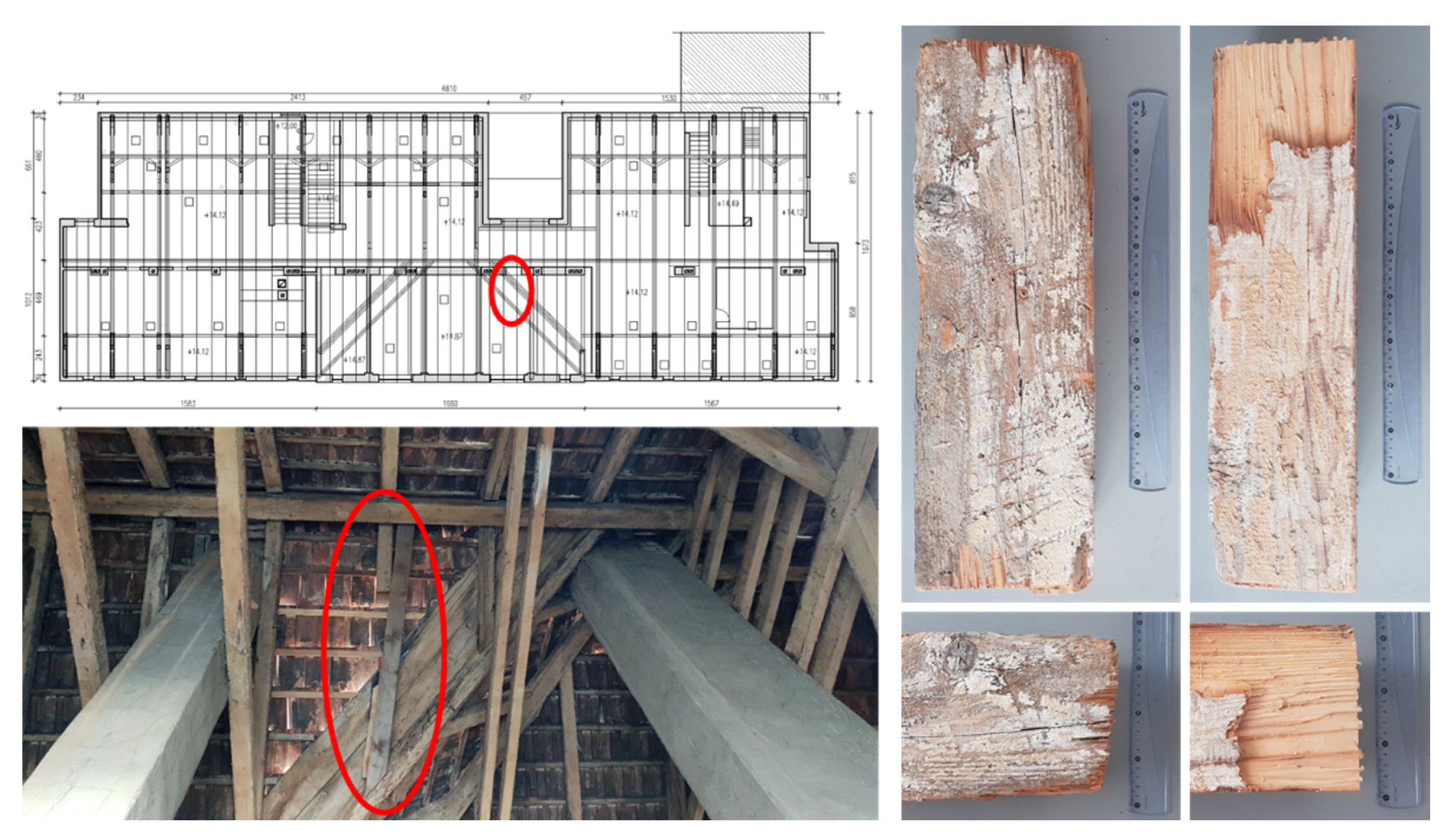
The material density test was performed on a sample of timber taken from the load-bearing element of the roof structure. The load-bearing element, i.e., the roof rafter, was removed from the system during the emergency repair of the roof structure when due to the leakage of water from the roof there was significant degradation of the element; thus, it was replaced with a new one. The degraded element was found deposited in the attic space, where rot was recorded at 2/3 of the length of the element, while 1/3 of the element (observed from the end) was characterized as healthy. Therefore, when taking the sample, special care was taken that the sample contained only healthy material. It was impossible to take additional samples from the load-bearing elements without replacing them with new ones. Therefore, the material density test was based on only one sample shown in Figure 17.
A test prism was formed from the sample taken to determine the exact material density (Figure 18). The digital cross-sectional gauge determined the prism cross-sectional dimension of 100 × 100 mm and a length of 400 mm. Although the device’s accuracy is 1/10 mm, the results are given to the nearest one millimeter. By technical drying, the prism was heated to a constant temperature of 100 ± 3 °C, weighing to steady-state. The mass of the dried prism of 1565 g was determined with a digital scale. Although the device’s accuracy is 1/10 g, the results are given with an accuracy of one gram. All tests were performed following the standards HRN ISO 13061: 2015 [27], as well as the standards HRN RN 384: 2016 [26] and HRN EN 408: 2012 [28]. The test results indicate a mean value of wood density of 438 kg/m3 (with an equilibrium of moisture content in the wood of 12%), where the wood density is given as the ratio of wood mass to volume of the test prism.
Given that the value of the dynamic modulus of elasticity of wood is not less than 11.0 MPa, and the mean value of the tested density of 420 kg/m3, it can be considered that the structure meets the structure requirements of classification in wood class C24. To determine the timber class, a dense arrangement of rings in the cross-section of the test prism was observed, i.e., a dense structure of the wood mass, which indicates a higher class of wood. However, investigative tests have established a lower density of wood than is usual for higher classes, which is caused by the loss of density with aging, that is, the hollowing of the material over time. In addition, the expected degradation of the modulus of elasticity over time has been established, and it can be assumed that the strengths have changed only negligibly, which can be proved by additional tests.
5.2. Post-Earthquake Inspection
After the earthquake with the epicenter near the city of Zagreb, a quick inspection of the attic space was performed. Although no damage was observed on the load-bearing elements or joint of the roof structure, the collapse of the chimney and gable walls was noticed. However, their partial fall or breakage of their parts did not cause damage to the roof structure itself. In addition to the above-mentioned damage, much more significant damages were noticed in the form of diagonal cracks in the attic wall on the south side, as well as the breakage of parts of the inner wall. It was concluded that the resulting cracks are not of such a level as to endanger the current stability of the roof structure, but that their propagation can lead to the collapse of part of the roof because these elements represent supports. In the time after the earthquake, emergency intervention measures were carried out, repairing the gable walls and chimneys, which were supported by the roof structure, to ensure stability and prevent collapse in case of further lateral actions.
Post-earthquake damage inspection after the earthquake with the epicenter near the town of Petrinja was performed in more detail. Although the location itself is quite far from the epicenter, the larger amplitudes caused larger deformations, in contrast to the earthquake near Zagreb, which resulted in higher energy, but lower amplitudes. The inspection was based on a systematic visual inspection of the general stability of the structure, the condition of the load-bearing elements, the condition of the joints, and the condition of the roof supports. In addition, the condition of previously damaged and partially repaired secondary elements was considered.
During the inspection, it was concluded that the global stability of the roof structure was not disturbed and that there was no new damage to the elements due to exceeding the load-bearing capacity. The reason for this is the properly formed bracing system in the plane and out of the frame plane.
The most attention during the post-earthquake examination was taken by the joints where a typical example of improper form was noticed. All tensile joints were made with clamps and screws and there was no damage. On another side, all compression joints were made as carpentry joints. Part of the compression joints on the elements of larger cross-sections, made in the form of a notch, also did not suffer damage because it was additionally secured with clamps; thus, it managed to take the tensile force. However, a significant part of the compression joints on elements of smaller cross-sections is made without fuse. During the impact of the earthquake and the structure translation, there was an alternating distribution of compressive and tensile forces in the elements. As the structure was designed only for gravitational and wind loads, the load-bearing elements and joints found themselves in an unnatural state. The result was a loss of load-bearing capacity of the pressure elements performed in the form of mortise and tenon or notched joints, and even the ejection of individual elements from the system, as can be seen in Figure 19.
The cracks in the walls that form the supports further expanded (Figure 20). An additional crack parallel to the existing one was formed on the wall of the southern attic. The reason for this is the significant load on the bay beam during an earthquake, whose axis is laid exactly in the direction of the cracks. A part of the top of the wall, that is, several rows of bricks, was carved on the inner wall. The reason for this is the poor load-bearing capacity of the masonry, with the top of the wall failing to take on a horizontal reaction on the support of the tie beam. No new damage was noticed on the secondary elements, and as they were restrained by intervention actions, there was no new collapse of parts of the chimney and gable walls.
The overall condition of the roof structure after two significant earthquakes can be assessed as satisfactory given that it is a large-span and massive roof. During retrofitting, special attention should be paid to securing the joints between the load-bearing elements and to repairing and strengthening the walls as supports for the roof structure.
6. Discussion and Conclusions
Based on similar case studies from the recent earthquakes [29,30,31,32], the assessment of the existing building is made in order to determine its seismic resistance and to show the damage both on masonry and timber elements. Investigative tests have shown that the structure is in relatively good condition, but that the replacement of the degraded roof elements is of paramount importance as well as retrofitting of masonry parts due to earthquake consequences. In this manuscript, the focus was set on timber structural elements.
Elements on which degradation appeared due to water leakage and the appearance of decay, should be entirely replaced with new ones. The new elements should be at least C24 graded timber and dried to the level of 15% moisture content. Elements that exceed the ultimate limit state must be strengthened. Reinforcement of the elements must be performed by adding timber tie beams to the sides of the existing elements or replacing the roof’s existing structural elements with new ones. Steel clamps and self-drilling screws should make all joints between the elements. Special attention should be paid to the timber cracking at the joints to prevent further splitting of the elements and to avoid brittle failure modes [33].
Furthermore, during the reconstruction and potential extension, special attention should be paid to the expansion joint of the new part of the floor structure as well as the floor layers from the existing tie-beam of the roof structure. It is recommended to perform the expansion in such a way that a layer of 50 mm thick insulation is installed below and above the tie beam, and a layer of 25 mm thick on the side, such that all loads on the floor structure are not transferred directly to/or indirectly through the tie beam. The entire roof structure must be protected from direct exposure atmospherics during the reconstruction, extension, and overhaul.
Most often, repairs of roof structures are related to the replacement of worn-out elements, strengthening of elements with insufficient load-bearing capacity, or filling cracks in cracked elements [34]. During retrofitting, the influence of the spatial stability of the roof structure is often forgotten, especially when space changes are made. The influence of secondary elements such as chimneys and gables are also forgotten when the roof takes on a stabilizing role during earthquake impact. In addition, the question of detail is questionable. The condition of the carpenter’s details is usually taken for granted, not having in mind the possibility of changing the distribution of forces in the system during lateral actions [35]. In order to ensure the correct way of repair, it is important to have appropriate and quality data of the structural condition and use them for more detailed analyses. As more and more popular and frequent actions lately, energy repairs of the roof are an ideal motive for quality repairs and the construction itself. With minimal interventions, in addition to the basic repair activities, it is always recommended to secure the carpenter’s joints with self-drilling screws, scratch the rafters with wood panels to make a diaphragm, as well as connect the roof and secondary elements, but only in combination with previous action (failure to do so may damage chimneys and gables). Precisely, the combination of structural and energy assessment, when the initial investment is approximately 30% higher, it is also considered the most profitable in terms of what is obtained.
Many assessment techniques are promising methods for a quantitative description of the current condition of timber members in timber structures. These concern material properties such as moisture content, density, and modulus of elasticity, and structural properties such as dynamic characteristics, localization of inhomogeneities, cracks, and biological attacks [36]. Inspection of earthquake damage, in particular, the details to pay attention to, requires experience because the prescribed methodology provides only framework instructions [35]. Although some methods and instruments are of high quality and necessary for the evaluation of structures, some devices do not guarantee the value for which they were designed. For more accurate post-earthquake assessment and structural analysis it is necessary to know some additional scientific conclusions that are not sufficiently researched. Here, the problem of quality and behavior of connection between the timber beams of the floor structure and the masonry walls can be singled out. In addition, the influence of existing and new layers on stiffness of the floor structure as rigid diaphragm or behavior of carpenter joints under cyclic loads should be further investigated.
The absence of standardized assessment methodology and methods may result in substandard reconstruction and reinforcement of timber structures [37,38,39]. The reinforcement of existing timber structures has been the subject of considerable research and development in recent years. However, there is currently a lack of harmonized European standards in this field. A systematic review of criteria to be used in the assessment of load-bearing timber structures in seismic active area was the main objective of this paper as well as the illustration of non-destructive and semi-destructive test methods through a case study involving roof construction of a hundred-year-old building in Zagreb, Croatia.
Delivery of the basis for advanced assessment and design of existing structures allows for a more economic design and accurate analysis of the consequences of failure, which is a part of the ARES project in which all the authors of the manuscript are highly involved.
Author Contributions
Conceptualization, M.S., V.R., N.P. and J.B.; methodology, M.S., N.P. and V.R.; software, N.P. and M.S.; validation, N.P., J.B. and V.R.; formal analysis, N.P., M.S. and J.B.; investigation, M.S., N.P., J.B. and V.R.; resources, M.S., V.R. and N.P.; data curation, J.B. and N.P.; writing—original draft preparation, N.P., M.S. and J.B.; writing—review and editing, N.P., M.S. and J.B.; visualization, M.S., N.P. and J.B.; supervision, V.R.; project administration, V.R. and M.S.; funding acquisition, M.S. All authors have read and agreed to the published version of the manuscript.
Funding
This research was partially funded by the Croatian Science Foundation, grant number UIP-2019-04-3749 (ARES project—assessment and rehabilitation of existing structures—development of contemporary methods for masonry and timber structures), project leader: Mislav Stepinac.
Institutional Review Board Statement
Not applicable.
Informed Consent Statement
Not applicable.
Data Availability Statement
Data available on request due to restrictions, e.g., privacy or ethical. The data presented in this study are available on request from the corresponding author.
Conflicts of Interest
The authors declare no conflict of interest. The funders had no role in the design of the study; in the collection, analyses, or interpretation of data; in the writing of the manuscript, or in the decision to publish the results.
References
- Stepinac, M.; Gašparović, M. A review of emerging technologies for an assessment of safety and seismic vulnerability and damage detection of existing masonry structures. Appl. Sci. 2020, 10, 5060. [Google Scholar] [CrossRef]
- Saloustros, S.; Pelà, L.; Contrafatto, F.R.; Roca, P.; Petromichelakis, I. Analytical Derivation of Seismic Fragility Curves for Historical Masonry Structures Based on Stochastic Analysis of Uncertain Material Parameters. Int. J. Archit. Herit. 2019, 13, 1142–1164. [Google Scholar] [CrossRef]
- Vlachakis, G.; Vlachaki, E.; Lourenço, P.B. Learning from failure: Damage and failure of masonry structures, after the 2017 Lesvos earthquake (Greece). Eng. Fail. Anal. 2020, 117, 104803. [Google Scholar] [CrossRef]
- Government of Croatia, World Bank Report: Croatia Earthquake Rapid Damage and Needs Assessment; Government of Croatia: Zagreb, Croatia, 2020.
- Stepinac, M.; Kisicek, T.; Renić, T.; Hafner, I.; Bedon, C. Methods for the assessment of critical properties in existing masonry structures under seismic loads-the ARES project. Appl. Sci. 2020, 10, 1576. [Google Scholar] [CrossRef] [Green Version]
- Stepinac, M.; Lourenço, P.B.; Atalić, J.; Kišiček, T.; Uroš, M.; Baniček, M.; Novak, M.Š. Damage classification of residential buildings in historical downtown after the ML5.5 earthquake in Zagreb, Croatia in 2020. Int. J. Disaster Risk Reduct. 2021, 56, 102140. [Google Scholar] [CrossRef]
- Uroš, M.; Šavor Novak, M.; Atalić, J.; Sigmund, Z.; Baniček, M.; Demšić, M.; Hak, S. Post-earthquake damage assessment of buildings—Procedure for conducting building inspections. Gradjevinar 2021, 72, 1089–1115. [Google Scholar] [CrossRef]
- Ortega, J.; Vasconcelos, G.; Rodrigues, H.; Correia, M. Assessment of the influence of horizontal diaphragms on the seismic performance of vernacular buildings. Bull. Earthq. Eng. 2018, 16, 3871–3904. [Google Scholar] [CrossRef]
- Mirra, M.; Ravenshorst, G.; van de Kuilen, J.W. Experimental and analytical evaluation of the in-plane behaviour of as-built and strengthened traditional wooden floors. Eng. Struct. 2020, 211, 110432. [Google Scholar] [CrossRef]
- Parisi, M.A.; Tardini, C. Seismic vulnerability assessment of timber roof structures: Criteria and procedures. Proc. Inst. Civ. Eng. Struct. Build. 2021, 174, 431–442. [Google Scholar] [CrossRef]
- Jeleč, M.; Varevac, D.; Rajčić, V. Križno lamelirano drvo (CLT)—Pregled stanja područja. Gradjevinar 2018, 70, 75–95. [Google Scholar] [CrossRef] [Green Version]
- Stepinac, M.; Rajčić, V.; Barbalić, J. Inspection and condition assessment of existing timber structures. J. Croat. Assoc. Civ. Eng. 2017, 69, 861–873. [Google Scholar] [CrossRef] [Green Version]
- Sediek, O.A.; El-Tawil, S.; McCormick, J. Dynamic Modeling of In-Event Interdependencies in Community Resilience. Nat. Hazards Rev. 2020, 21, 04020041. [Google Scholar] [CrossRef]
- Vona, M.; Mastroberti, M.; Mitidieri, L.; Tataranna, S. New resilience model of communities based on numerical evaluation and observed post seismic reconstruction process. Int. J. Disaster Risk Reduct. 2018, 28, 602–609. [Google Scholar] [CrossRef]
- The Database of Usability Classification. In Croatian Centre of Earthquake Engineering (HCPI-Hrvatski Centar Za Potresno Inženjerstvo); University of Zagreb: Zagreb, Croatia, 2020.
- Stepinac, M.; Rajčić, V.; Honfi, D. Condition Assessment of Timber Structures—Quantifying the Value of Information. In Proceedings of the 40th IABSE Symposium, Nantes 2018: Tomorrow’s Megastructures, Nantes, France, 19–21 September 2018. [Google Scholar] [CrossRef]
- Palma, P.; Steiger, R. Structural health monitoring of timber structures—Review of available methods and case studies. Constr. Build. Mater. 2020, 248, 118528. [Google Scholar] [CrossRef]
- Krause, M.; Dackermann, U.; Li, J. Elastic wave modes for the assessment of structural timber: Ultrasonic echo for building elements and guided waves for pole and pile structures. J. Civ. Struct. Health Monit. 2015, 5, 221–249. [Google Scholar] [CrossRef] [Green Version]
- López, G.; Basterra, L.A.; Acuña, L. Estimation of wood density using infrared thermography. Constr. Build. Mater. 2013, 42, 29–32. [Google Scholar] [CrossRef]
- Rajčić, V.; Stepinac, M.; Barbalić, J. In Situ Advanced Diagnostics and Inspection by Non-destructive Techniques and UAV as Input to Numerical Model and Structural Analysis—Case Study. Commun. Comput. Inf. Sci. 2018, 962, 359–371. [Google Scholar] [CrossRef]
- Dietsch, P.; Kreuzinger, H. Guideline on the assessment of timber structures: Summary. Eng. Struct. 2011, 33, 2983–2986. [Google Scholar] [CrossRef]
- Harte, A.; Jockwer, R.; Stepinac, M.; Descamps, T.; Rajcic, V.; Dietsch, P. Reinforcement of timber structures—The route to standardisation. In Proceedings of the International Conference on Structural Health Assessment of Timber Structures, Guimarães, Portugal, 25–27 September 2019; pp. 78–89. [Google Scholar]
- CEN. EN 17121:2019: Conservation of Cultural Heritage—Historic Timber Structures—Guidelines for the on-Site Assessment of Load-Bearing Timber Structures. 2019. Available online: http://31.45.242.218/HZN/Todb.nsf/wFrameset2?OpenFrameSet&Frame=Down&Src=%2FHZN%2FTodb.nsf%2F51ab863e2feef8fec1256d4a00370fd8%2Fbbd0a0140b7d55dec125815c002ea683%3FOpenDocument%26AutoFramed (accessed on 10 October 2021).
- Piazza, M.; Riggio, M. Visual strength-grading and NDT of timber in traditional structures. J. Build. Apprais. 2008, 3, 267–296. [Google Scholar] [CrossRef] [Green Version]
- Eurocode 5: Design of Timber Structures—Part 1-1: General—Common Rules and Rules for Buildings (EN 1995-1-1:2004/A2:2014). Available online: https://www.phd.eng.br/wp-content/uploads/2015/12/en.1995.1.1.2004.pdf (accessed on 10 October 2021).
- CEN. EN 13183-2:2008, Moisture Content of a Piece of Sawn Timber—Part 2: Estimation by Electrical Resistance Method. 2008. Available online: https://repozitorij.hzn.hr/norm/HRN+EN+13183-2%3A2008 (accessed on 10 October 2021).
- EN 338:2016—Structural Timber—Strength Classes. Available online: https://standards.iteh.ai/catalog/standards/cen/492c108d-268a-4cbd-9b59-3f31792887c5/en-338-2016 (accessed on 20 July 2021).
- CEN. EN 384:2016: Structural Timber-Determination of Characteristic Values of Mechanical Properties and Density. 2016. Available online: https://standards.iteh.ai/catalog/standards/cen/cee07f35-6e03-4179-903f-84a644d33af3/en-384-2016 (accessed on 10 October 2021).
- ISO 13061-1:2015: Physical and Mechanical Properties of Wood—Test Methods for Small Clear Wood Specimens—Part 1: Determination of Moisture Content for Physical and Mechanical Tests. 2014. Available online: https://www.iso.org/standard/60063.html (accessed on 10 October 2021).
- EN 408:2012: Timber Structures—Structural Timber and Glued Laminated Timber—Determination of Some Physical and Mechanical Properties. 2012. Available online: https://standards.iteh.ai/catalog/standards/cen/6ffae6c9-5eaf-4c84-8bf3-5132cbfc563c/en-408-2010a1-2012 (accessed on 20 July 2021).
- Tomassetti, U.; Correia, A.A.; Graziotti, F.; Penna, A. Seismic vulnerability of roof systems combining URM gable walls and timber diaphragms. Earthq. Eng. Struct. Dyn. 2019, 48, 1297–1318. [Google Scholar] [CrossRef]
- Bai, W.; Moustafa, M.A.; Dai, J.; Yang, Y.; Du, K.; Chen, X. Damage assessment of Shuanghe Confucian temple after Changning earthquake mainshock and aftershocks series. Bull. Earthq. Eng. 2021, 19, 5977–6001. [Google Scholar] [CrossRef]
- Aloisio, A.; di Battista, L.; Alaggio, R.; Antonacci, E.; Fragiacomo, M. Assessment of structural interventions using Bayesian updating and subspace-based fault detection methods: The case study of S. Maria di Collemaggio basilica, L’Aquila, Italy. Struct. Infrastruct. Eng. 2021, 17, 141–155. [Google Scholar] [CrossRef]
- Wu, C.; Xue, J.; Zhou, S.; Zhang, F. Seismic Performance Evaluation for a Traditional Chinese Timber-frame Structure. Int. J. Archit. Herit. 2020, 1–15. [Google Scholar] [CrossRef]
- Cabrero, J.M.; Yurrita, M. Performance assessment of existing models to predict brittle failure modes of steel-to-timber connections loaded parallel-to-grain with dowel-type fasteners. Eng. Struct. 2018, 171, 895–910. [Google Scholar] [CrossRef]
- Cruz, H.; Yeomans, D.; Tsakanika, E.; Macchioni, N.; Jorissen, A.; Touza, M. Guidelines for on-site assessment of historic timber structures. Int. J. Archit. Herit. 2015, 9, 277–289. [Google Scholar] [CrossRef]
- Tannert, T.; Dietsch, P.; Branco, J. Reinforcement of Timber Elements in Existing Structures; RILEM State Art Reports; Springer: Berlin, Germany, 2021; Volume 33. [Google Scholar] [CrossRef]
- Krause, M.; Kurz, J.; Lanata, F.; Cavalli, A. Needs for further developing monitoring and NDT-methods fir timber structures. In Proceedings of the 3rd International Conference on Structural Health Assessment of Timber Structures, Wroclaw, Poland, 9–11 September 2015; pp. 89–99. [Google Scholar]
- Rajcic, V.; Barbalić, J.; Perković, N. Seismic and energy renovation of masonry or RC framed buildings with timber or composite timber panels. In Proceedings of the 1st Croatian Conference on Earthquake Engineering (1CroCE), Zagreb, Croatia, 22–24 March 2021. [Google Scholar]
Figure 1.
(a) Magnitudes from the 22 March earthquake in Zagreb; (b) Magnitudes from the 30 December 2020 earthquake in Petrinja.
Figure 1.
(a) Magnitudes from the 22 March earthquake in Zagreb; (b) Magnitudes from the 30 December 2020 earthquake in Petrinja.
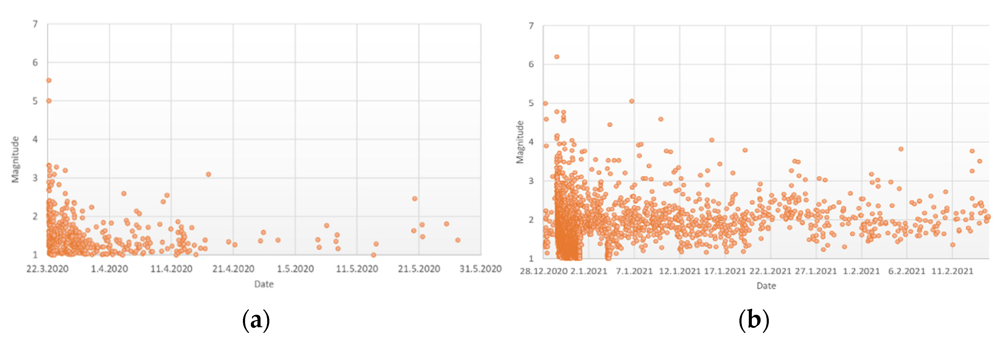
Figure 2.
Typical timber roof structure systems in continental Croatia.
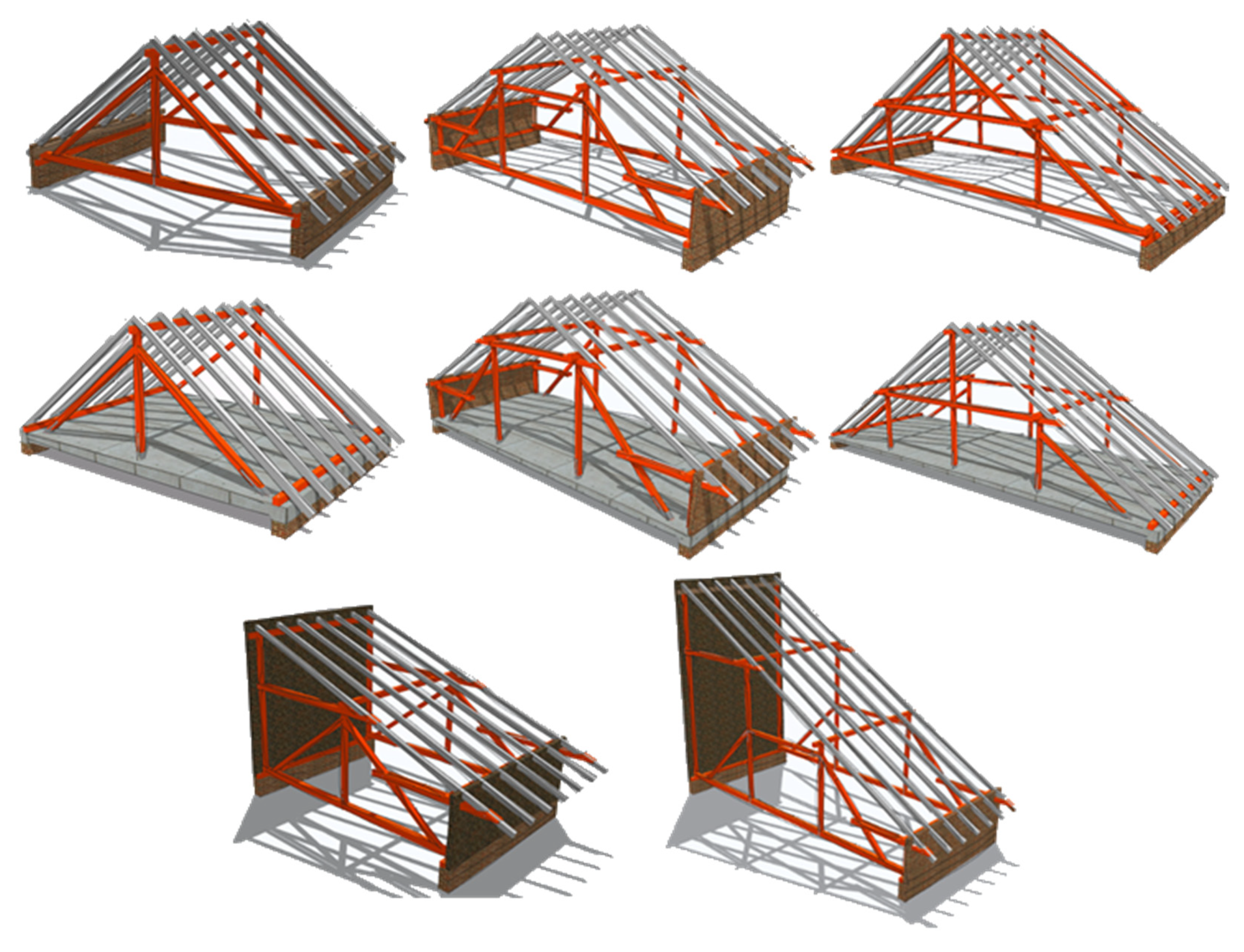
Figure 3.
Typical damages to masonry buildings are caused by the homogeneity of timber roof systems and poor connection with masonry walls and elements.
Figure 3.
Typical damages to masonry buildings are caused by the homogeneity of timber roof systems and poor connection with masonry walls and elements.
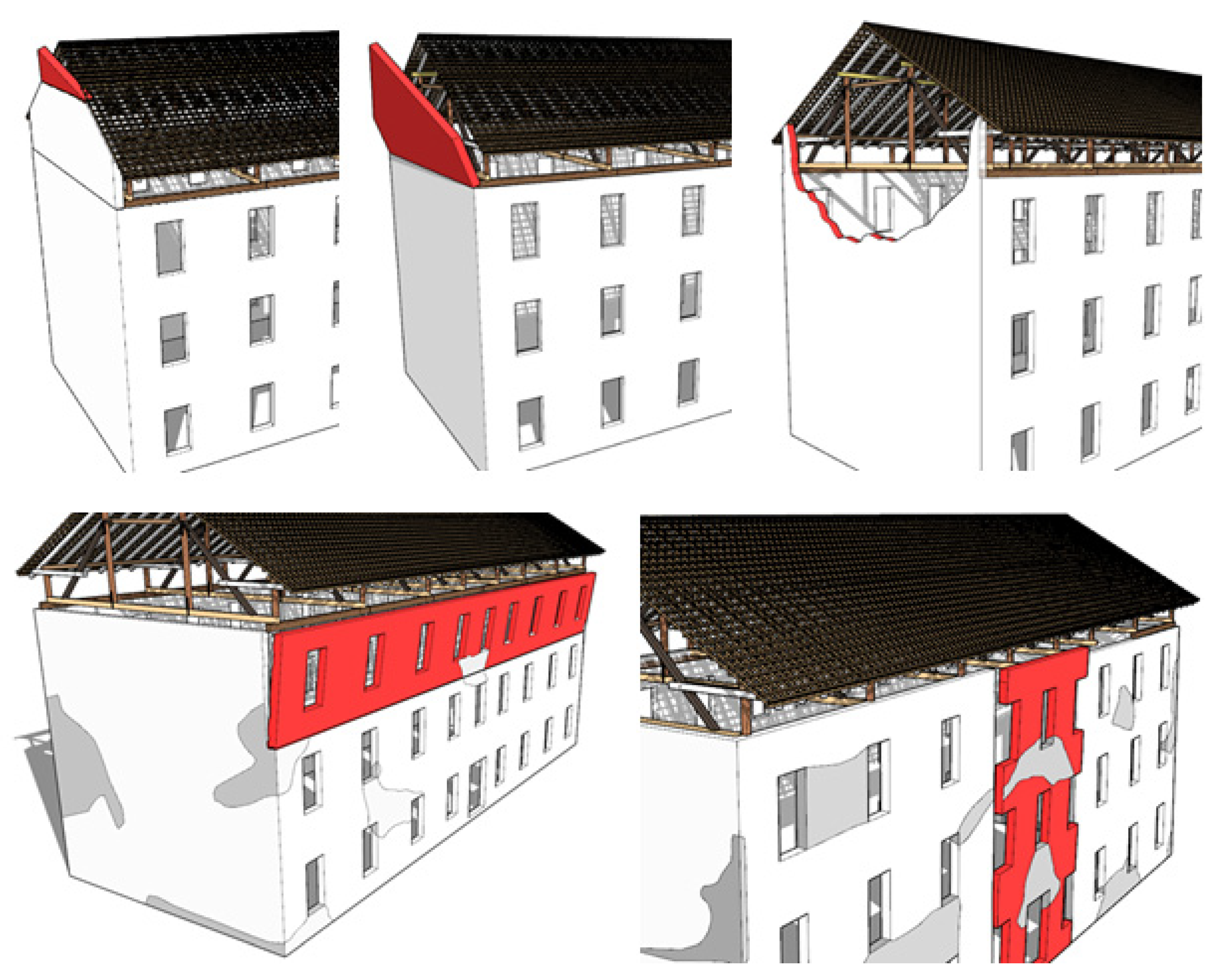
Figure 4.
Damages to the roofs and chimneys. (Photo credit: Mislav Stepinac).

Figure 5.
Damages to the timber roof structure are due to the failure of the chimney. (Photo credit: Mislav Stepinac).
Figure 5.
Damages to the timber roof structure are due to the failure of the chimney. (Photo credit: Mislav Stepinac).

Figure 6.
Damages to the timber roof structure are due to a lack of (out of plane) bracing system. (Photo credit: Jure Barbalić).
Figure 6.
Damages to the timber roof structure are due to a lack of (out of plane) bracing system. (Photo credit: Jure Barbalić).

Figure 7.
Damages to the timber roof structure are due to the improper design of carpentry compression joints. (Photo credit: Jure Barbalić).
Figure 7.
Damages to the timber roof structure are due to the improper design of carpentry compression joints. (Photo credit: Jure Barbalić).

Figure 8.
Damage to improper modification of the attic space or improper construction of the roof structure itself. (Photo credit: HCPI and Mislav Stepinac).
Figure 8.
Damage to improper modification of the attic space or improper construction of the roof structure itself. (Photo credit: HCPI and Mislav Stepinac).

Figure 9.
Damages to the timber roof structure due to ingress of moisture in combination with earthquake impact. (Photo credit: Jure Barbalić).
Figure 9.
Damages to the timber roof structure due to ingress of moisture in combination with earthquake impact. (Photo credit: Jure Barbalić).
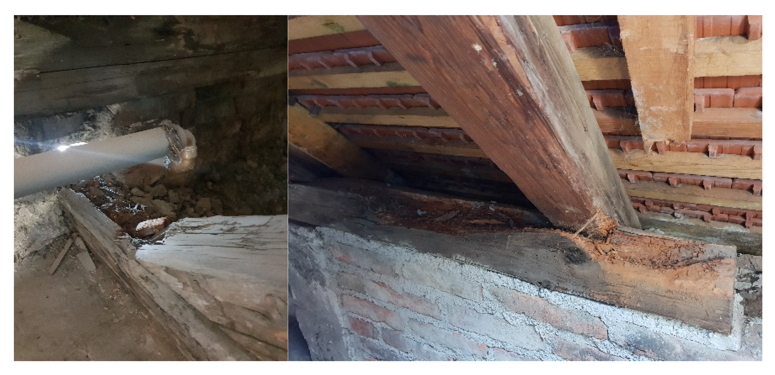
Figure 10.
Damage to the timber roof systems and roof coverings in the two respected historic parts of Zagreb [13].
Figure 10.
Damage to the timber roof systems and roof coverings in the two respected historic parts of Zagreb [13].
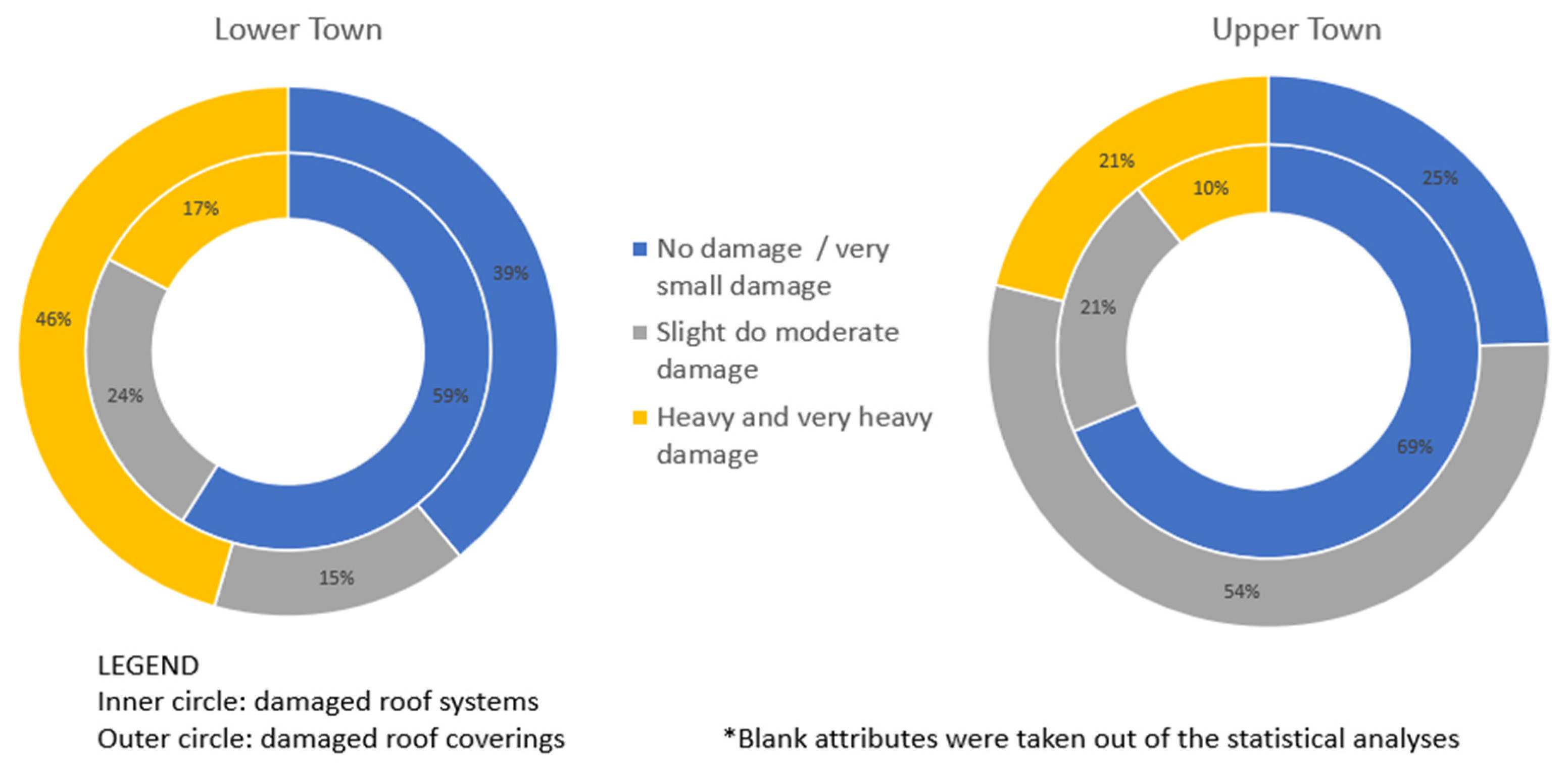
Figure 11.
General view of the building.
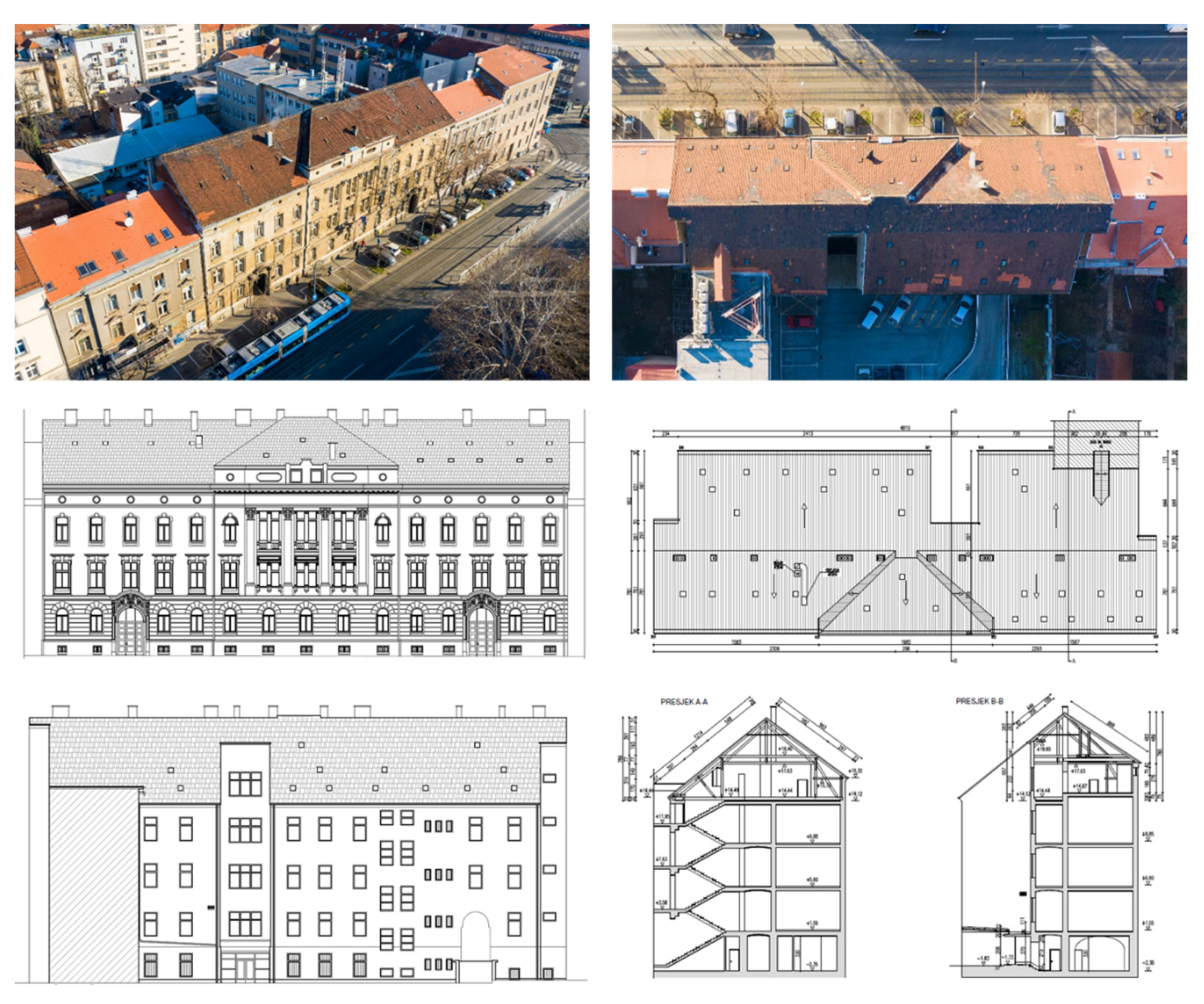
Figure 12.
Actions needed for different assessment phase.
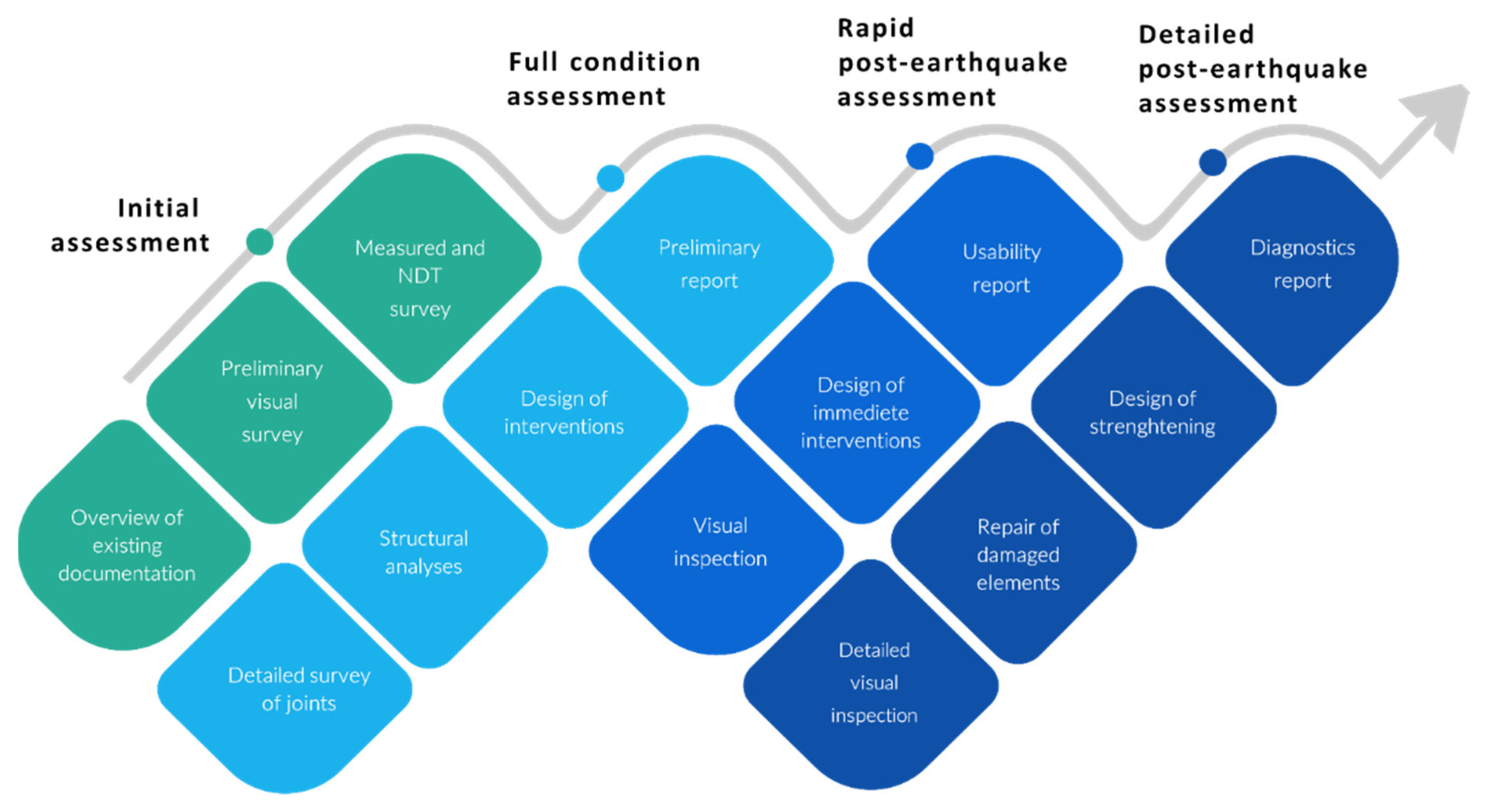
Figure 13.
A 3D model of roof timber structures: (a) northside view; (b) southside view; (c) view from the inside.
Figure 13.
A 3D model of roof timber structures: (a) northside view; (b) southside view; (c) view from the inside.
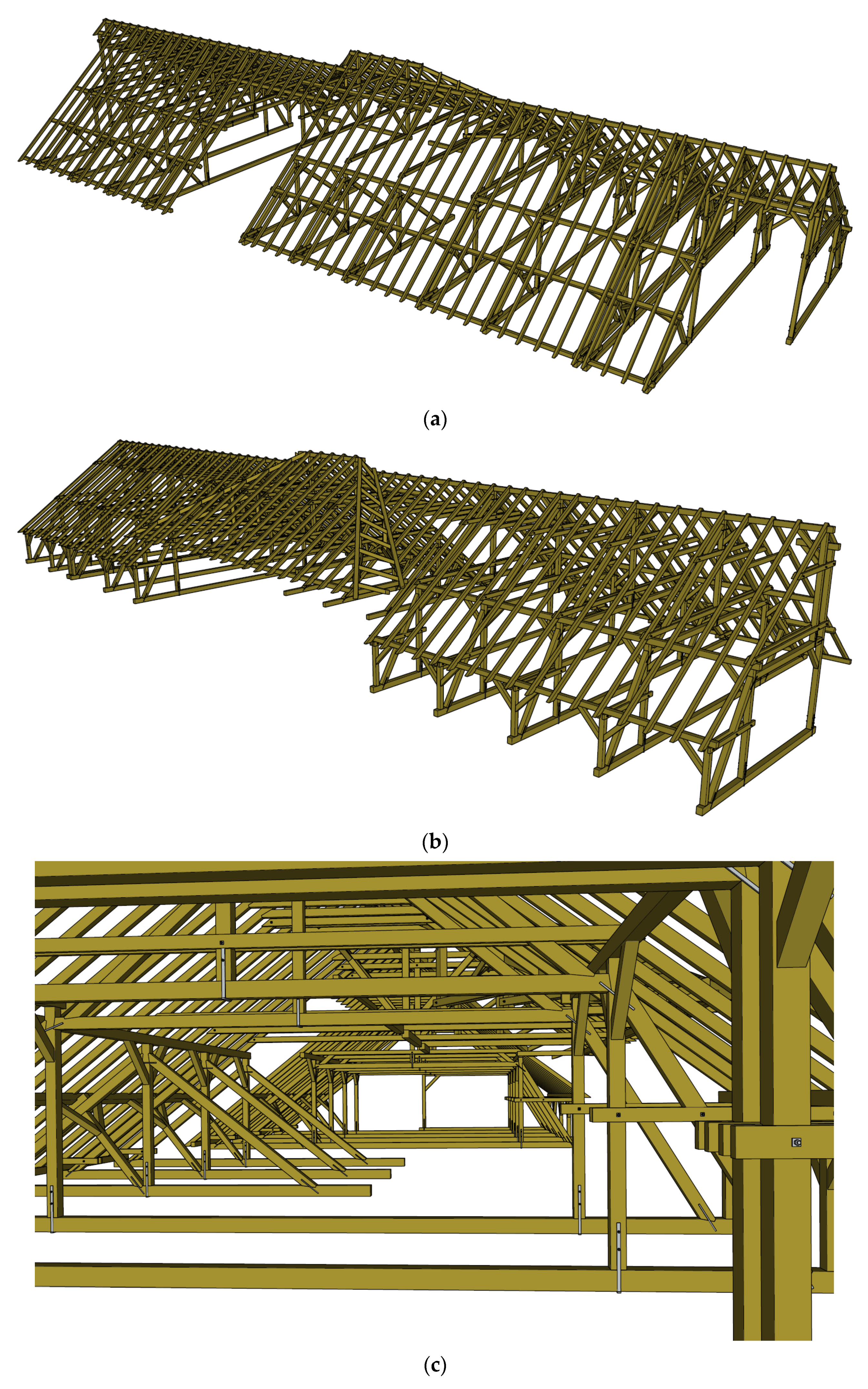
Figure 14.
Probe positions and positions of damaged elements are shown in the construction plan.
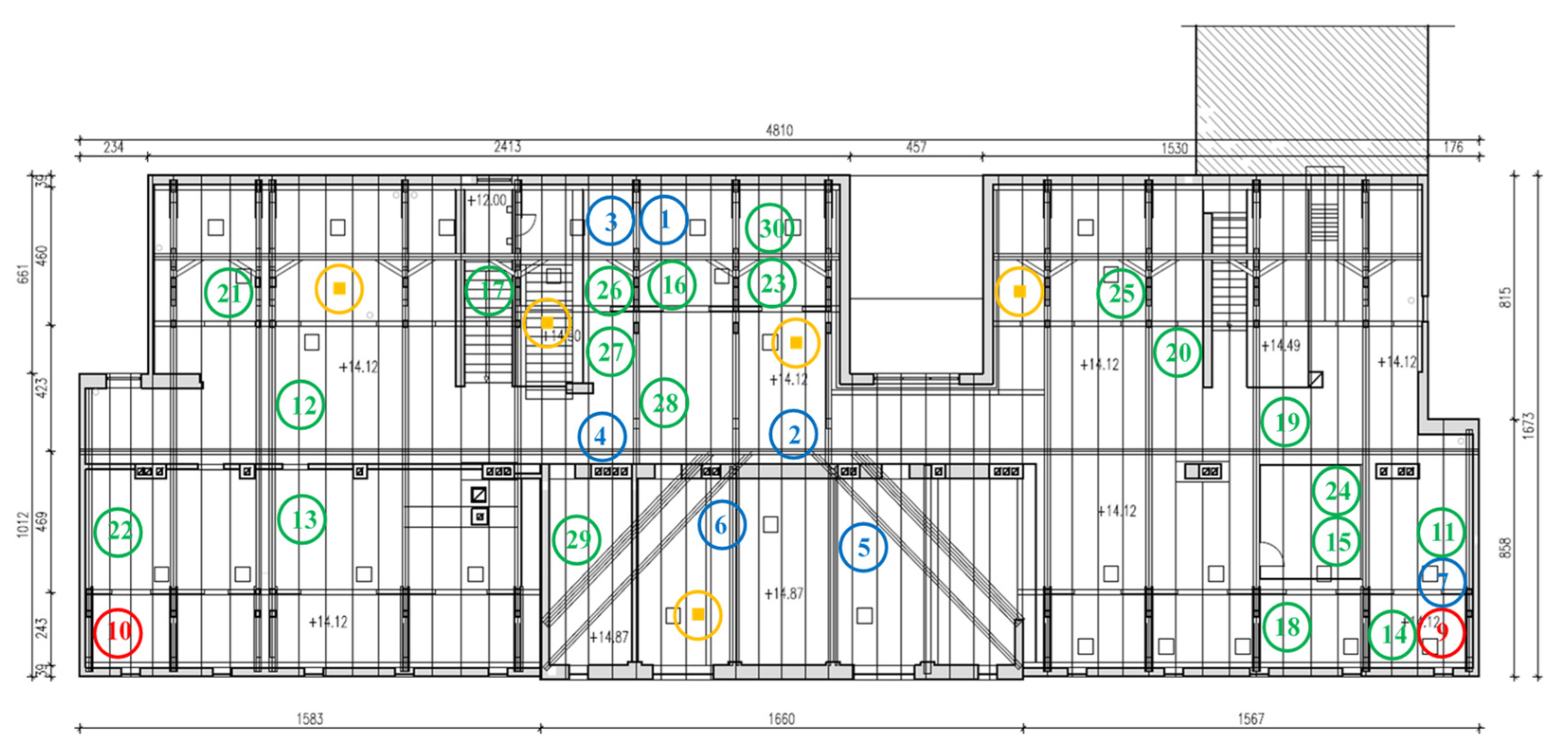
Figure 15.
Overview of typical element damage (arranged in order): POZ16, POZ 11, and POZ23; POZ1 and POZ5; POZ9 and POZ10.
Figure 15.
Overview of typical element damage (arranged in order): POZ16, POZ 11, and POZ23; POZ1 and POZ5; POZ9 and POZ10.
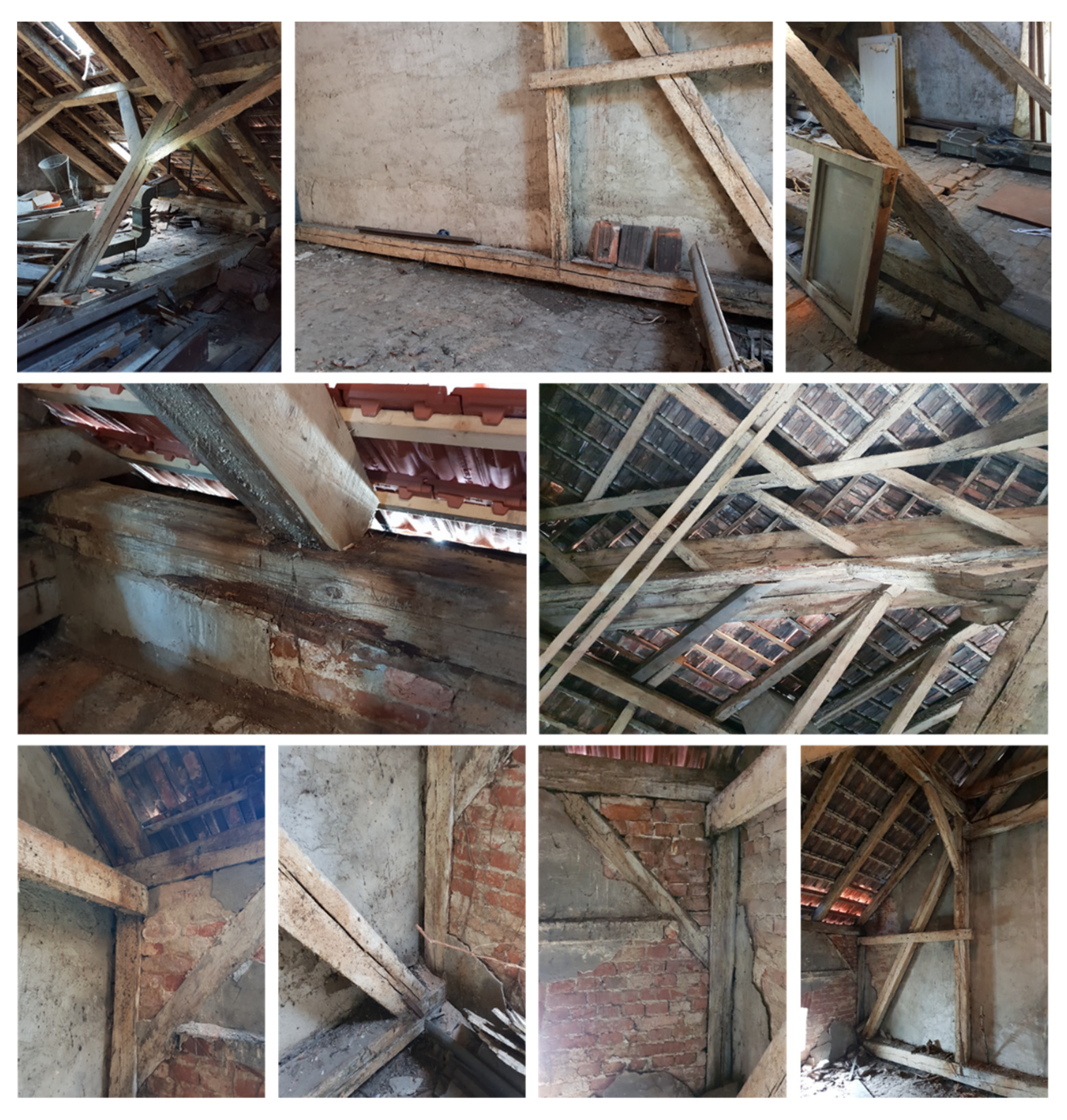
Figure 16.
Positions for moisture content and dynamic MOE measurements positions.

Figure 17.
Sampling position for material density testing.

Figure 18.
View of the prism-shaped sample finished for material density testing.
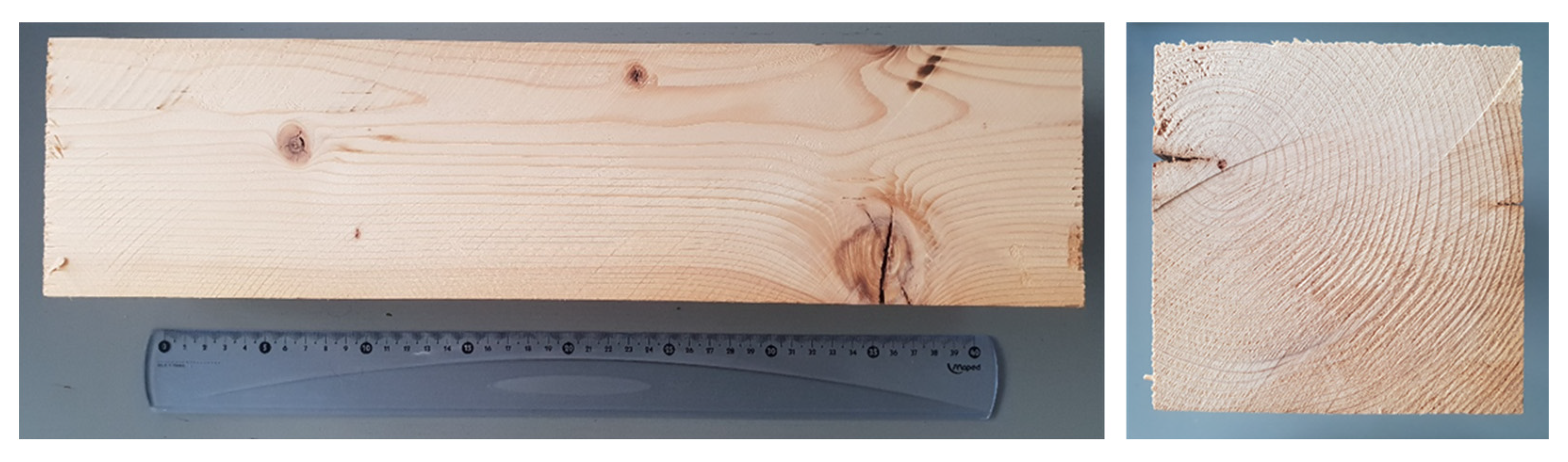
Figure 19.
Overview of damage element after earthquakes impact—the collapse of the collar beam element due to ejection under the distribution of forces (from compression to tensile).
Figure 19.
Overview of damage element after earthquakes impact—the collapse of the collar beam element due to ejection under the distribution of forces (from compression to tensile).
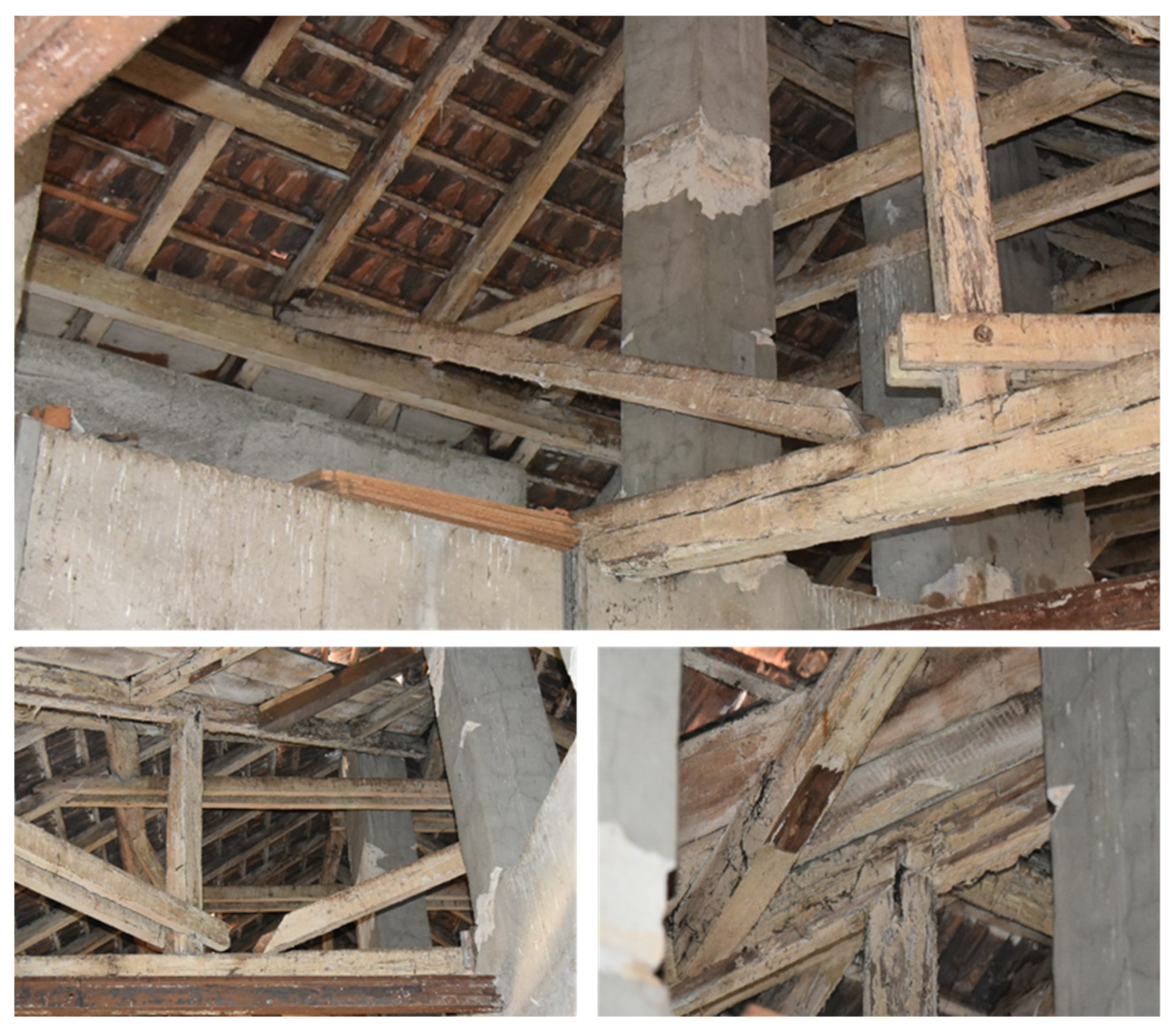
Figure 20.
Overview of damage element after earthquakes impact—damaged of masonry walls in the function of roof structure supports.
Figure 20.
Overview of damage element after earthquakes impact—damaged of masonry walls in the function of roof structure supports.

Table 1.
Moisture content measurements results.
| Element | Local Measuring Position | Axis | ||||||||
|---|---|---|---|---|---|---|---|---|---|---|
| 1 | 3 | 5 | 7 | 8 | 10 | 11 | 13 | 15 | ||
| wall purlin | MCbottom (%) | 13.7/15.6 | 12.5/14.3 | 13.3/12.8 | 13.9/13.9 | 13.6/14.2 | 13.8/13.7 | 13.4/14.6 | 12.9/13.2 | 14.1/13.8 |
| MCtop (%) | 13.9/11.9 | 12.6/11.7 | 13.2/11.9 | 13.7/11.8 | 13.9/11.4 | 14.2/11.6 | 13.7/11.8 | 13.2/11.9 | 13.8/12.0 | |
| joist | MCsupport (%) | 14.1/15.6 | 13.6/13.6 | 13.8/12.9 | 14.5/14.3 | 14.7/15.3 | 14.9/14.6 | 13.9/14.2 | 13.5/13.4 | 14.6/14.0 |
| MCspan (%) | 13.7/13.9 | 12.5/11.7 | 13.1/12.8 | 11.6/11.9 | 11.7/11.2 | 11.9/11.4 | 13.6/13.8 | 13.9/14.1 | 14.2/14.4 | |
| strut | MCsupport (%) | 13 | 12.8 | 13.1 | 12.9 | 13.4 | 13.2 | 12.8 | 13.3 | 13.6 |
| MCspan (%) | 12.2 | 12.1 | 11.7 | 11.4 | 11.6 | 11.4 | 11.9 | 12.1 | 11.9 | |
| column | MCsupport (%) | 12.8/12.5 | 12.6/12.2 | 12.3/11.8 | 13.0/12.1 | 13.1/12.6 | 12.2/12.4 | 12.7/12.3 | 12.7/13.0 | 13.3/13.2 |
| MCspan (%) | 12.3/12.1 | 11.9/11.6 | 11.3/10.9 | 11.5/11.4 | 11.8/11.3 | 11.9/11.4 | 12.1/11.8 | 11.9/12.1 | 12.3/12.4 | |
| knee brace | MCsupport (%) | 12.8/12.5 | 12.3/12.1 | 12.1/11.5 | 12.2/12.3 | 12.7/12.3 | 12.5/12.1 | 12.9/12.3 | 12.7/12.6 | 12.9/12.8 |
| MCspan (%) | 12.5/12.3 | 12.2/11.9 | 11.7/11.4 | 11.9/11.8 | 12.6/11.7 | 12.3/11.9 | 12.8/12.2 | 12.4/12.3 | 12.5/12.5 | |
| purlin | MCsupport (%) | 12.6/12.5 | 12.9/12.1 | 13.1/12.3 | 13.4/11.9 | 13.8/12.2 | 12.9/12.8 | 12.6/12.4 | 12.8/12.6 | 13.1/12.7 |
| MCspan (%) | 12.3/12.1 | 12.5/11.9 | 12.9/12.0 | 13.1/11.8 | 13.3/12.2 | 12.2/12.6 | 11.9/11.8 | 12.4/12.1 | 12.6/12.3 | |
| collar tie | MCsupport (%) | 11.1 | 11 | 11.3 | 11.2 | 11.7 | 11.9 | 11.2 | 11.5 | 11.6 |
| MCspan (%) | 10.9 | 10.7 | 11 | 10.8 | 11.3 | 11.4 | 10.9 | 11 | 11.2 | |
| hanger | MCsupport (%) | 11 | 10.9 | 11.1 | 10.8 | 11.2 | 11.1 | 10.7 | 11.3 | 11.2 |
| MCspan (%) | 10.8 | 10.6 | 10.7 | 10.7 | 11 | 10.9 | 10.5 | 10.9 | 11 | |
| cleat | MCsupport (%) | 10.0/10.1 | 9.8/9.9 | 9.9/9.9 | 10.1/9.8 | 10.2/9.9 | 10.0/9.8 | 9.9/9.7 | 10.1/9.8 | 10.2/10.3 |
| MCspan (%) | 9.9/9.8 | 9.9/9.7 | 9.6/9.9 | 9.8/9.7 | 10.0/9.8 | 10.1/9.2 | 9.9/9.7 | 10.1/9.9 | 10.1/10.2 | |
| rafter | MCsupport (%) | 12.8/11.3 | 13.0/11.6 | 13.5/12.1 | 13.4/11.9 | 13.9/12.3 | 13.5/12.6 | 13.8/12.2 | 13.2/12.5 | 14.1/12.8 |
| MCspan (%) | 11.2/10.6 | 11.4/10.8 | 11.8/10.7 | 11.6/10.7 | 11.8/11.1 | 11.9/10.9 | 11.4/10.8 | 11.6/11.2 | 12.1/11.4 | |
Table 2.
Dynamic MOE (parallel to the grain) measurements results.
| Element | Local Measuring Position | Axis | ||||||||
|---|---|---|---|---|---|---|---|---|---|---|
| 1 | 3 | 5 | 7 | 8 | 10 | 11 | 13 | 15 | ||
| wall purlin | Ebottom (GPa) | 12.6/14.3 | 11.5/13.1 | 12.2/11.7 | 12.7/12.7 | 12.5/13 | 12.6/12.6 | 12.3/13.4 | 11.8/12.1 | 12.9/12.6 |
| Etop (GPa) | 12.7/10.9 | 11.5/10.7 | 12.1/10.9 | 12.6/10.8 | 12.7/10.4 | 13.0/10.6 | 12.6/10.8 | 12.1/10.9 | 12.6/11.0 | |
| joist | Esupport (GPa) | 12.9/14.3 | 12.5/12.5 | 12.6/11.8 | 13.3/13.1 | 13.5/14.0 | 13.7/13.4 | 12.7/13.0 | 12.4/12.3 | 13.4/12.8 |
| Espan (GPa) | 12.6/12.7 | 11.5/10.7 | 12.0/11.7 | 10.6/10.9 | 10.7/10.3 | 10.9/10.4 | 12.5/12.6 | 12.7/12.9 | 13.0/13.2 | |
| strut | Esupport (GPa) | 11.9 | 11.7 | 12 | 11.8 | 12.3 | 12.1 | 11.7 | 12.2 | 12.5 |
| Espan (GPa) | 11.2 | 11.1 | 10.7 | 10.4 | 10.6 | 10.4 | 10.9 | 11.1 | 10.9 | |
| column | Esupport (GPa) | 11.7/11.5 | 11.5/11.2 | 11.3/10.8 | 11.9/11.1 | 12.0/11.5 | 11.2/11.4 | 11.6/11.3 | 11.6/11.9 | 12.2/12.1 |
| Espan (GPa) | 11.3/11.1 | 10.9/10.6 | 10.4/10.0 | 10.5/10.4 | 10.8/10.4 | 10.9/11.1 | 11.1/10.8 | 10.9/11.1 | 11.3/11.4 | |
| knee brace | Esupport (GPa) | 11.7/11.5 | 11.3/11.1 | 11.1/10.5 | 11.2/11.3 | 11.6/11.3 | 11.5/11.1 | 11.8/11.3 | 11.6/11.5 | 11.8/11.7 |
| Espan (GPa) | 11.5/11.3 | 11.2/10.9 | 10.7/10.4 | 10.9/10.8 | 11.5/10.7 | 11.3/10.9 | 11.7/11.2 | 11.4/11.3 | 11.5/11.5 | |
| purlin | Esupport (GPa) | 11.5/11.5 | 11.8/11.1 | 12.0/11.3 | 12.3/10.9 | 12.6/11.2 | 11.8/11.7 | 11.5/11.4 | 11.7/11.5 | 12.0/11.6 |
| Espan (GPa) | 11.3/11.1 | 11.5/10.9 | 11.8/11.0 | 12.0/10.8 | 12.2/11.2 | 11.2/11.5 | 10.9/10.8 | 11.4/11.1 | 11.5/11.3 | |
| collar tie | Esupport (GPa) | 10.2 | 10.1 | 10.4 | 10.3 | 10.7 | 10.9 | 10.3 | 10.5 | 10.6 |
| Espan (GPa) | 10 | 9.8 | 10.1 | 9.9 | 10.4 | 10.4 | 10 | 10.1 | 10.3 | |
| hanger | Esupport (GPa) | 10.1 | 10 | 10.2 | 9.9 | 10.3 | 10.2 | 9.8 | 10.4 | 10.3 |
| Espan (GPa) | 9.9 | 9.7 | 9.8 | 9.8 | 10.1 | 10 | 9.6 | 10 | 10.1 | |
| cleat | Esupport (GPa) | 9.2/9.3 | 9.0/9.1 | 9.1/9.1 | 9.3/9.0 | 9.3/9.1 | 9.2/9.0 | 9.1/8.9 | 9.3/9.0 | 9.3/9.4 |
| Espan (GPa) | 9.1/9.0 | 9.1/8.9 | 8.8/9.1 | 9.0/8.9 | 9.2/9.0 | 9.3/8.4 | 9.1/8.9 | 9.3/9.1 | 9.3/9.3 | |
| rafter | Esupport (GPa) | 11.7/10.4 | 11.9/10.6 | 12.4/11.1 | 12.3/10.9 | 12.7/11.3 | 12.4/11.5 | 12.6/11.2 | 12.1/11.5 | 12.9/11.7 |
| Espan (GPa) | 10.3/9.7 | 10.4/9.9 | 10.8/9.8 | 10.6/9.8 | 10.8/10.2 | 10.9/10.0 | 10.4/9.9 | 10.6/10.3 | 11.1/10.4 | |
Publisher’s Note: MDPI stays neutral with regard to jurisdictional claims in published maps and institutional affiliations. |
© 2021 by the authors. Licensee MDPI, Basel, Switzerland. This article is an open access article distributed under the terms and conditions of the Creative Commons Attribution (CC BY) license (https://creativecommons.org/licenses/by/4.0/).
Share and Cite
MDPI and ACS Style
Perković, N.; Stepinac, M.; Rajčić, V.; Barbalić, J. Assessment of Timber Roof Structures before and after Earthquakes. Buildings 2021, 11, 528. https://doi.org/10.3390/buildings11110528
AMA Style
Perković N, Stepinac M, Rajčić V, Barbalić J. Assessment of Timber Roof Structures before and after Earthquakes. Buildings. 2021; 11(11):528. https://doi.org/10.3390/buildings11110528
Chicago/Turabian StylePerković, Nikola, Mislav Stepinac, Vlatka Rajčić, and Jure Barbalić. 2021. "Assessment of Timber Roof Structures before and after Earthquakes" Buildings 11, no. 11: 528. https://doi.org/10.3390/buildings11110528
Note that from the first issue of 2016, this journal uses article numbers instead of page numbers. See further details here.