Article

Assessment and Rehabilitation of Culturally Protected Prince Rudolf Infantry Barracks in Zagreb after Major Earthquake

1
Peoples Associates Structural Engineers—Zagreb Office, 10000 Zagreb, Croatia
2
Faculty of Civil Engineering, University of Zagreb, 10000 Zagreb, Croatia
3
A&A Architects, 20000 Dubrovnik, Croatia
4
Department of Architecture, Shinshu University, 4-17-1 Wakasato, Nagano 380-8553, Japan
*
Author to whom correspondence should be addressed.
Buildings 2021, 11(11), 508; https://doi.org/10.3390/buildings11110508
Submission received: 21 September 2021 / Revised: 22 October 2021 / Accepted: 25 October 2021 / Published: 27 October 2021

Abstract

:
Recently, Zagreb was struck by a strong earthquake. Damage throughout the city was tremendous due to numerous aged and vulnerable masonry buildings. Many damaged buildings are under a certain level of cultural heritage protection. Hence, reliable assessment and effective rehabilitation are important to preserve cultural significance and mitigate risk for human life. With that in mind, the procedure of a detailed condition assessment of the building under heritage protection is presented. A detailed historical background of the case study building is shown, and observed damage and conducted in situ tests are discussed. The nonlinear static seismic analysis performed in the 3Muri software is extensively elaborated. Four different levels of reconstruction according to new Croatian law are briefly presented. Additionally, several strengthening scenarios are proposed with various strengthening techniques.

1. Introduction

In March 2020, in the early morning hours, a strong earthquake occurred in Zagreb with a magnitude of ML = 5.5 and an intensity of VII on the Mercalli scale. The earthquake’s epicenter was located 10 km from Zagreb, with a hypocenter at a depth of about 10 km. The quake was felt throughout Croatia and in neighboring countries. In addition to great material damage, the earthquake took one young human life. Shortly after the main quake, a series of aftershocks followed. The quake was unexpected for the population, and the disaster response system was unprepared. Based on citizens’ reports, civil engineers inspected the facilities according to a pre-established methodology (EMS-98) and issued recommendations to citizens on the usability of about 26,000 facilities. The World Bank estimates the total financial damage from the Zagreb earthquake as EUR 11.3 billion [1]. Moderate to severe structural damage was sustained by 118 buildings, and heavy structural damage was reported in 41 buildings under heritage protection. The total damage to cultural heritage buildings is about EUR 1.38 billion, most of which was incurred in the city of Zagreb.
Most of the buildings in the center of Zagreb are traditional masonry buildings that are not designed for seismic actions. Such buildings were mostly constructed as interconnected load-bearing masonry walls with wooden floor structures [2]. Damage to such buildings occurs due to uneven stiffness distribution, inappropriate or nonexistent connections between the walls and poor connection to the roof and floor structure. An additional disadvantage is the absence of vertical and horizontal confining elements (e.g., reinforced concrete columns and beams on all corners and wall intersections as it is required today for this type of building and for such high seismic demand according to European seismic regulations), poor load-bearing capacity in its plane and insufficient load-bearing capacity of roof and floor structures [3]. Furthermore, most of the buildings in Zagreb are very old, so the degradation of mechanical properties should be considered. Commonly observed damage was: collapse and damage of chimneys, collapse and damage of attic gable walls, separation of gable walls, damage to the roof, damage to the cantilever elements, damage of the walls (out of and in the plane), damage to lintels and vaults, damage to partition walls, cracks in ceilings and damage to stairs [4]. More information about the earthquake itself, the level of preparedness and immediate actions and, finally, the consequences of the Zagreb earthquake can be found in [5,6,7,8].
After a strong earthquake, buildings should go through a well-established assessment process. A key part of this assessment should be the high-precision evaluation of the mechanical properties of masonry. This will reduce the number of unknowns related to the structure’s resistance [4]. Technology development facilitates improvements in the field of assessment methods, which then allow a more adequate, economic and safer assessment of existing buildings. A lot of research on this topic has been conducted in different parts of the world. Procedures, methods and norms related to the assessment of existing structures are constantly being improved [9,10,11,12,13,14]. Special attention is also paid to cultural heritage buildings that represent the identity of historic urban cores [15,16,17,18,19,20,21].
New methods such as drone imaging and laser scanning could ease and complement the regular assessment process. Unmanned aerial vehicles (UAVs) can be used for crisis management, crack identification, seismic damage, architectural assessment of cultural heritage and structural assessment of buildings. Laser scanning of structures (light detection and ranging (LiDAR)) is used to scan structures damaged by earthquakes to identify cracks and ways of failure of the element and the entire structure [22]. Additionally, the benefit of these two techniques is particularly visible when inspecting heritage buildings. Digital twins can be produced to preserve the state of the building and for its reconstruction (if needed). Many scientific articles and studies have been published regarding the modeling of the behavior of existing structures and their reconstruction. The reader is referred to the following articles related to the reconstruction of cultural heritage buildings. Case studies like the one described in this manuscript can be found in [2,18,23,24,25,26,27].
This paper presents the procedure of a detailed inspection of a building under cultural heritage protection. The case study building was damaged in the earthquake and needs to be renovated according to new laws in Croatia to ensure the safe and functional future use of the building.

2. Case Study of Rudolf’s Barracks

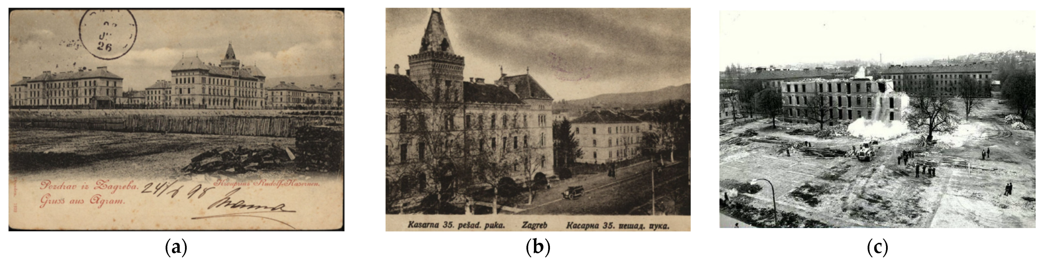
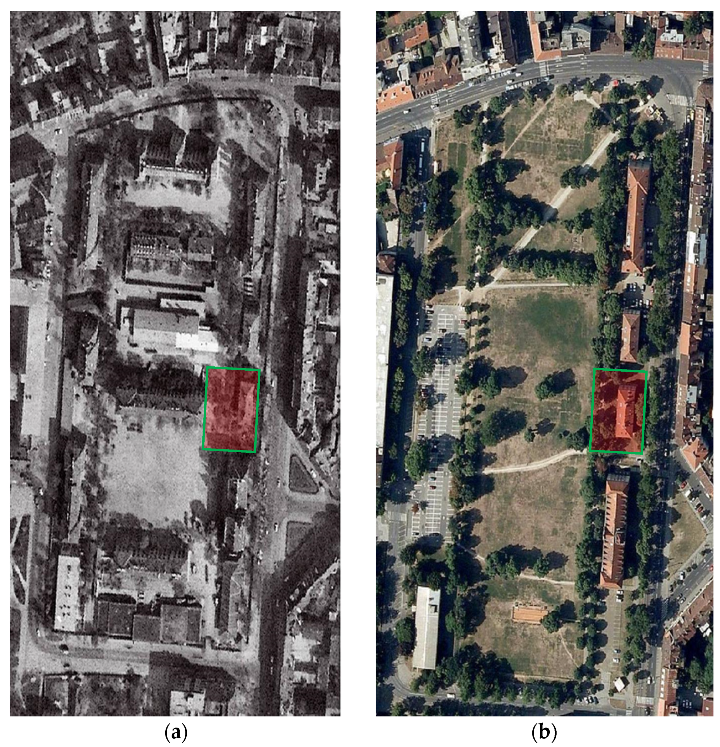
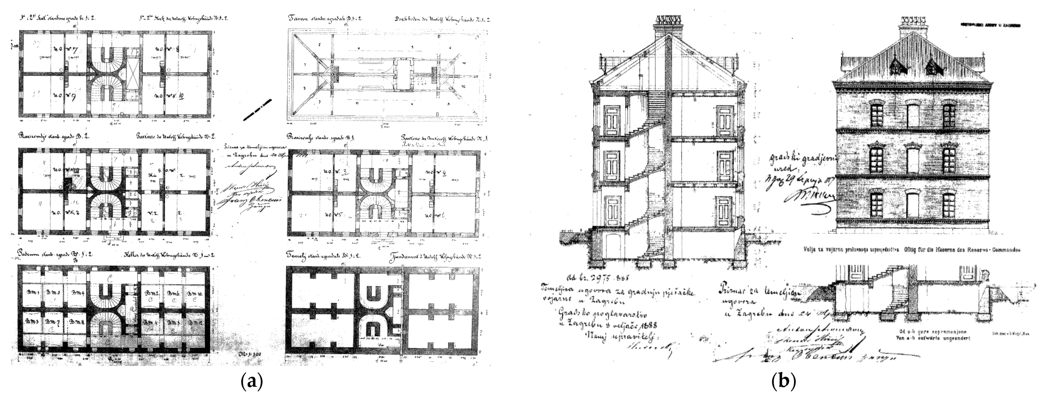
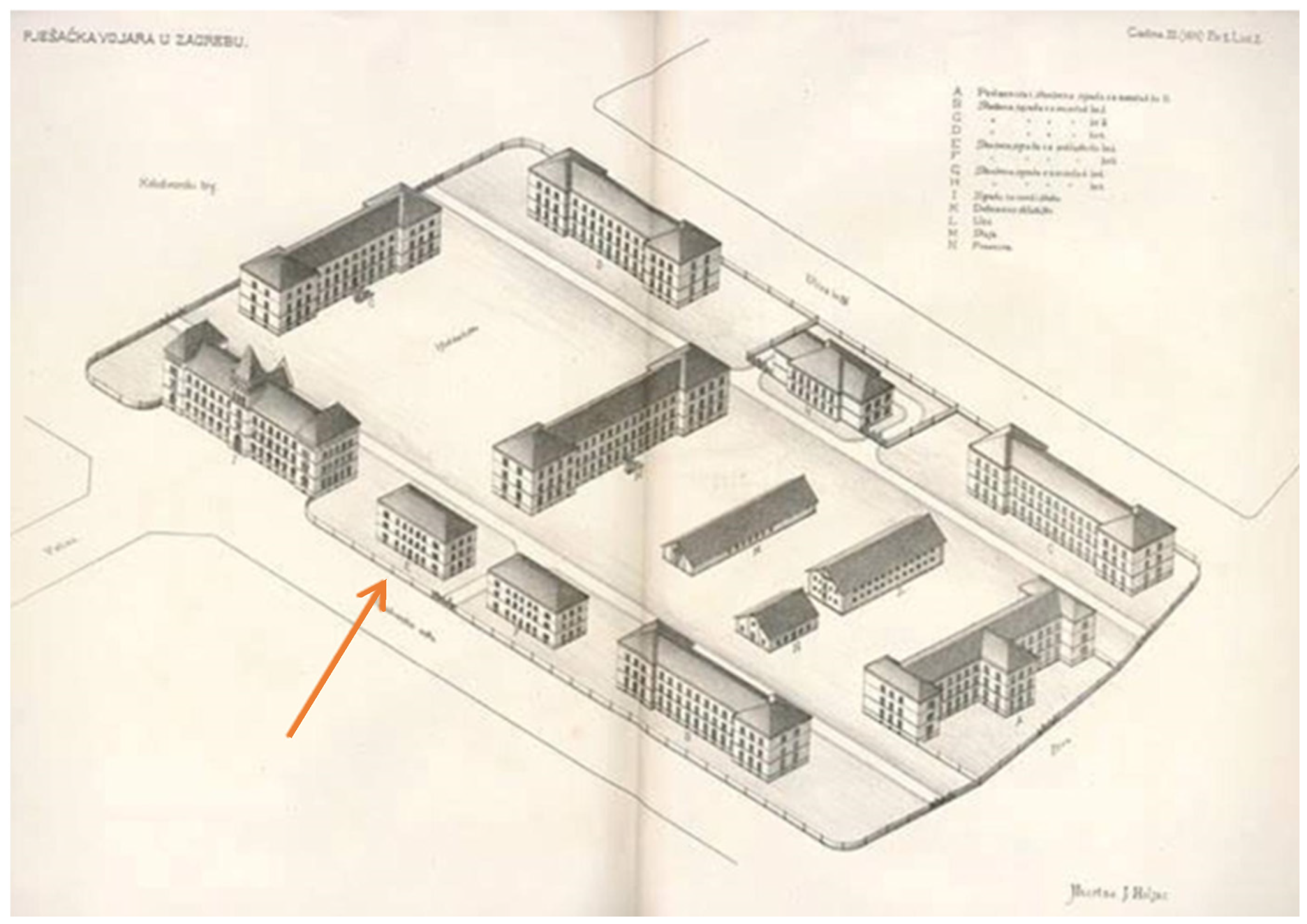
2.1. Historical Background

The case study building is located within the historic complex of buildings in the western part of Zagreb ‘Lower Town’ called the infantry barracks of Prince Rudolf. The entire complex of Rudolf’s barracks is protected as an immovable individual cultural property and is entered in the Register of Cultural Heritage of the Republic of Croatia. The protection of the complex refers to the main building and the entire area of the former pedestrian barracks complex with the existing quality greenery, unbuilt areas and peripheral buildings of high ambient values. The Rudolf’s barracks complex is located within the A protection zone of the Historical and Urban Entity of the city of Zagreb, protected as a cultural asset and entered in the Register of Cultural Heritage of the Republic of Croatia—List of Protected Cultural Heritage.
The infantry barracks complex was constructed in the period from 1887 to 1889 according to the project of the Viennese architects Franz Gruber and Carl Völckner. The complex consisted of 13 buildings (Figure 1 and Figure 2), most of which were two-story buildings, and was named after the son of Emperor Francis Joseph I and Empress Sisi, Prince Rudolf [28,29]. The entire complex was built within 15 months of Prince Rudolf laying the foundation stone, and the construction of the complex was triggered by tensions over the Austro-Hungarian occupation of Bosnia and Herzegovina and the need to house the army.
In the late 1970s, a decision was made to demolish Rudolf’s barracks (Figure 2c) to make the area a secondary city center, but it was converted into a park without new constructions. Part of the complex was demolished in 1978, and what is left are four buildings, the main representative and three more modest buildings, all built in the neo-romantic style. One of these buildings is the case study of this paper located at Republic Austria Street No. 18 (Figure 3).
Figure 4 shows the original drawings of the building in question, obtained from the State Archives in Zagreb.

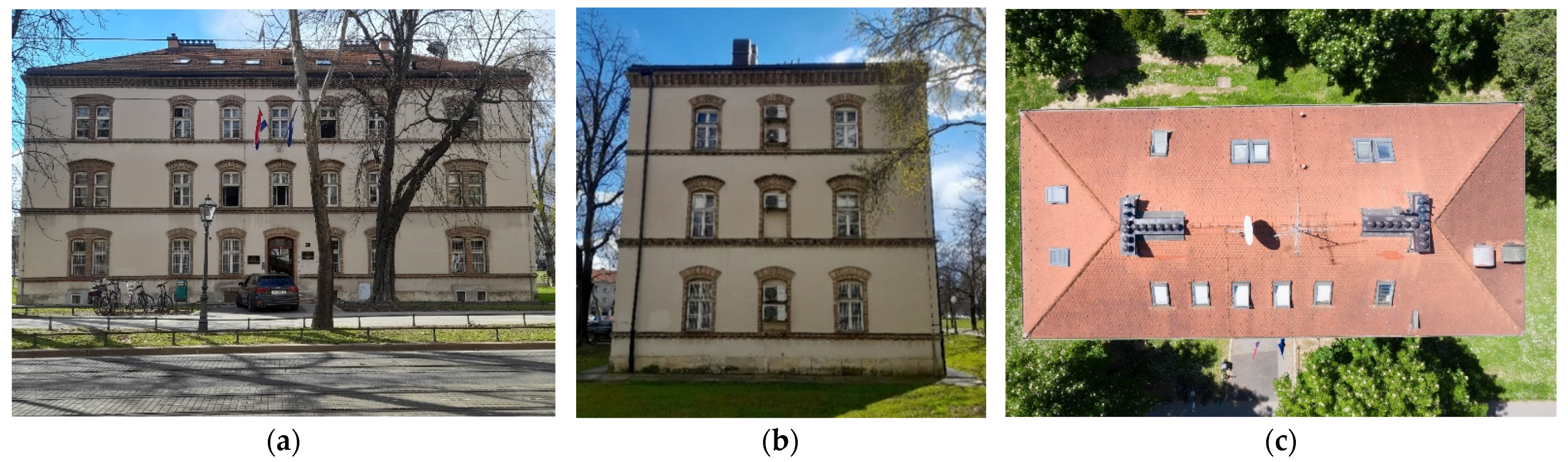
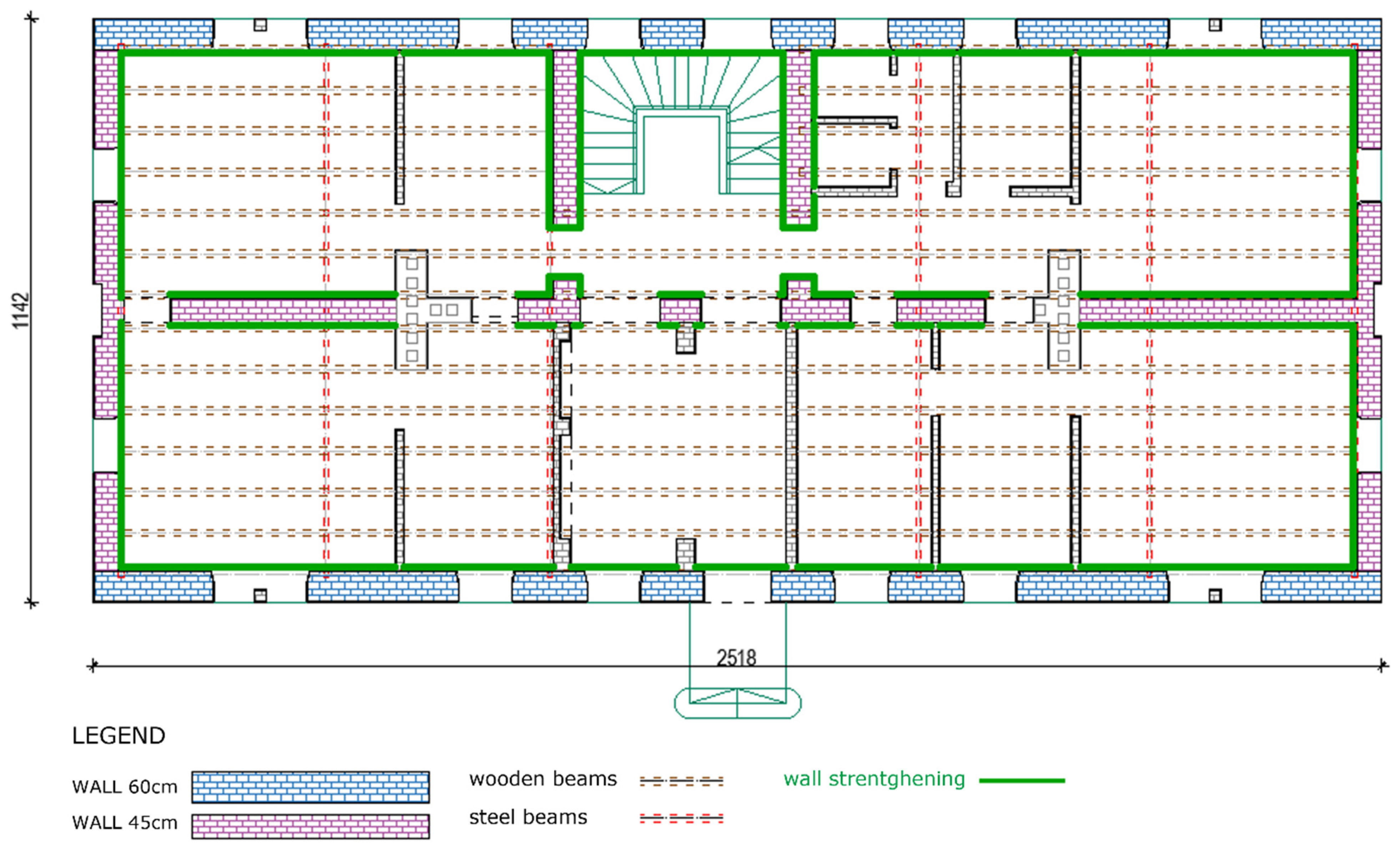
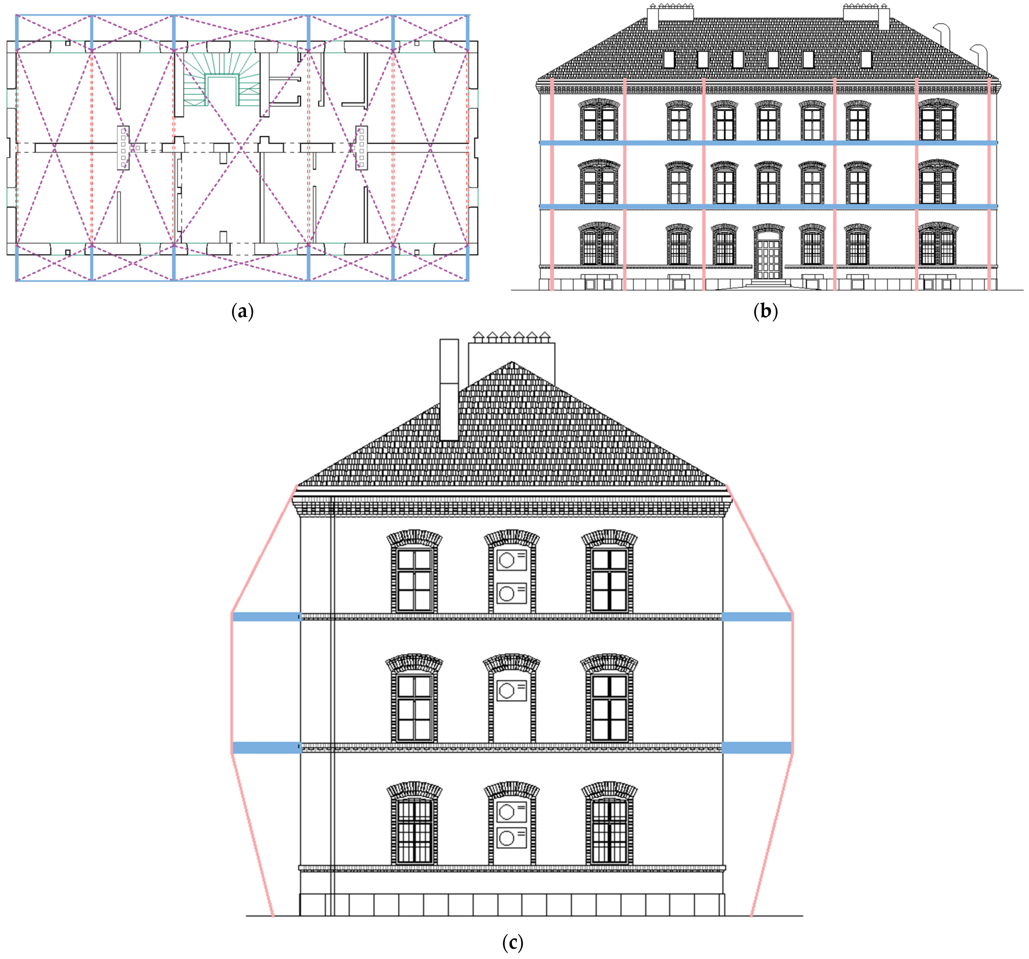
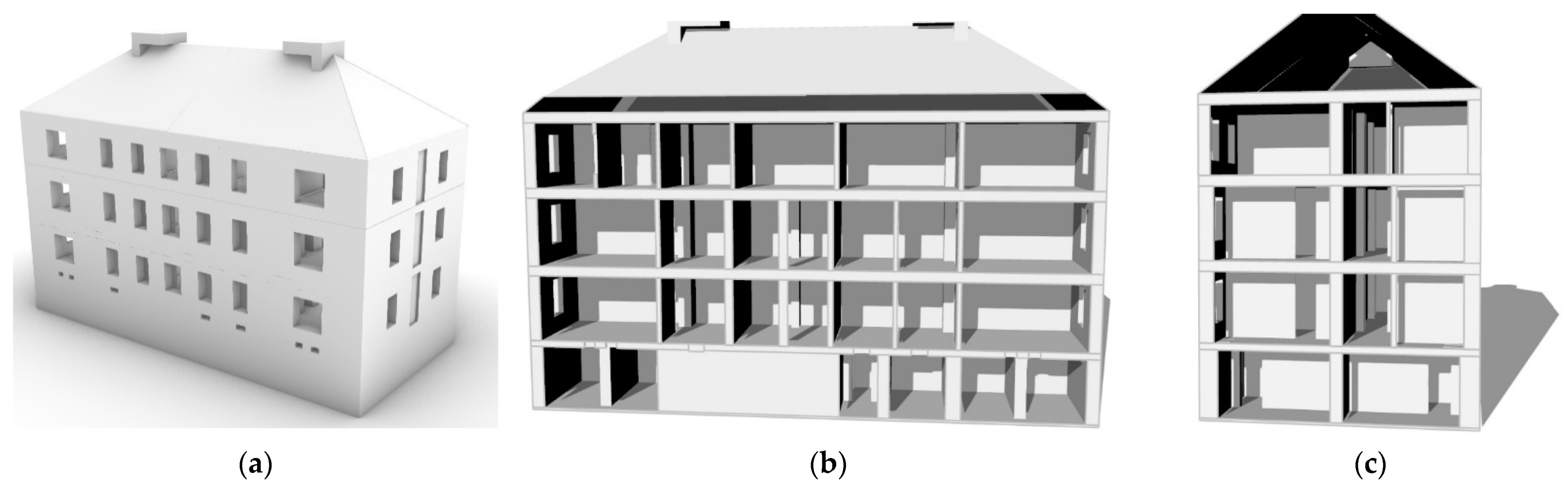
2.2. Today’s Building

The case study building (Figure 5) is a public-purpose building with a rectangular floor plan of 25.18 m × 11.42 m and a height of approximately 15.50 m. The floor area is approximately 290.00 m2, and the total gross area is approximately 1450 m2. The building consists of five floors, all floors of the building are used as office space. The building has undergone minor changes in the original geometry and space over time and has been properly maintained.
The load-bearing walls are made of solid bricks of the old Austro-Hungarian format 14 × 6.5 × 29 cm. The thicknesses of the load-bearing walls in the basement are 78 cm, 65 cm and 50 cm, at the ground floor 63 cm and 50 cm, and in the other aboveground floors, the thickness is 50 cm. The partition walls are made of solid brick, and the thickness is between 14 cm and 20 cm.
The ceiling structure in the basement is a brick vault supported by brick arches. The structure of the other floors consists of wooden beams and steel beams. The width of the wooden beams is 14 cm, and the height is 20 cm. The steel beam is an “I” profile, 200 mm high.
In the central part of the building, there is a new reinforced concrete cantilever three-legged staircase system.
As the building is under the protection of the Ministry of Culture, a detailed survey of the external dimensions and façade was made to preserve its architectural value. Laser scanning was performed with the Leica BLK360 device and processed in the Cyclone Register 360 software. With the help of laser scanning, a point cloud with a precision of 3 mm was obtained, and the façade with external geometric contours was preserved for the future. In addition, a digital “twin” of the building has been created, which will be used for further restoration works if needed (Figure 6).
After a detailed survey of the external geometry, the interior was recorded and measured. Finally, 2D and 3D models of the building were made (Figure 7).

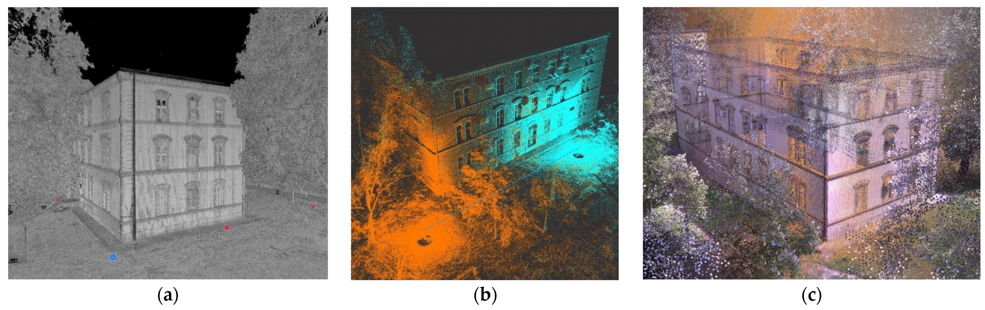
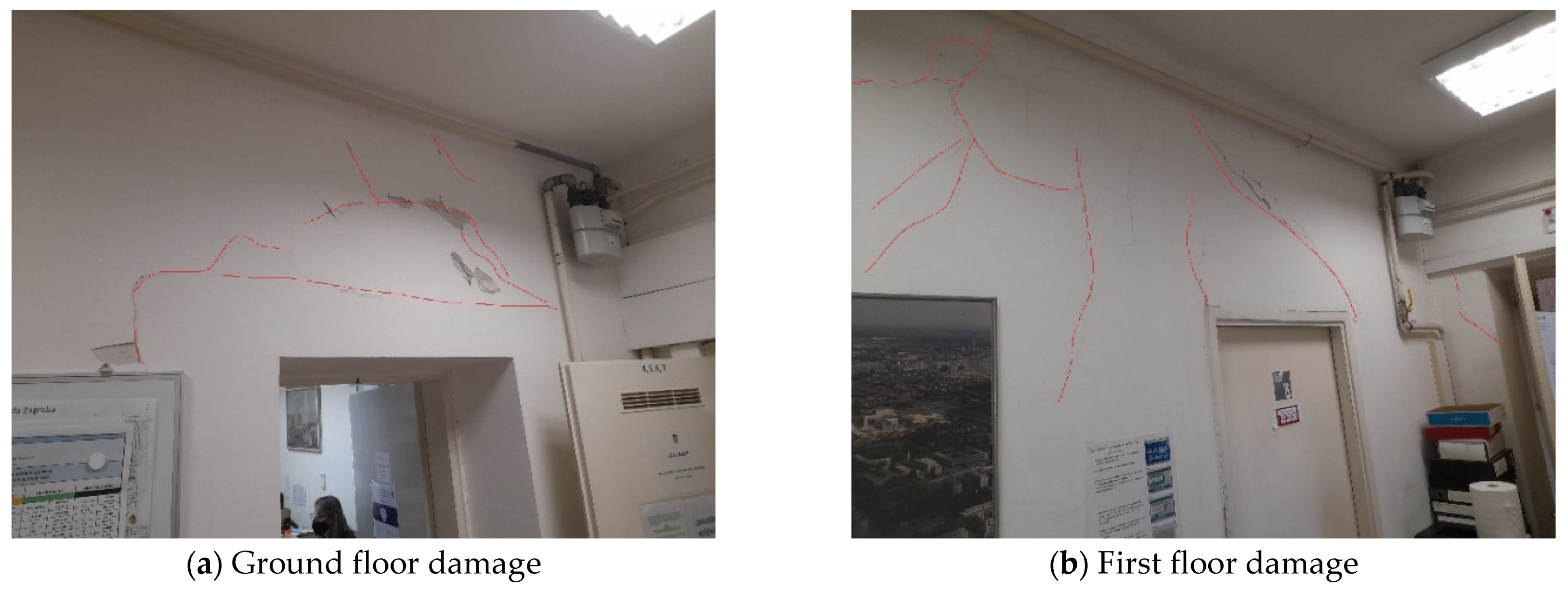
2.3. Damage Detection after Earthquake

The building was inspected after the earthquake on 22 March, 2020. It was assigned the usability mark PN2. The mark PN2 refers to buildings with moderate damage without risk of collapse, but the usability is questionable due to the potential risk of collapse of some elements. The following damage was found:
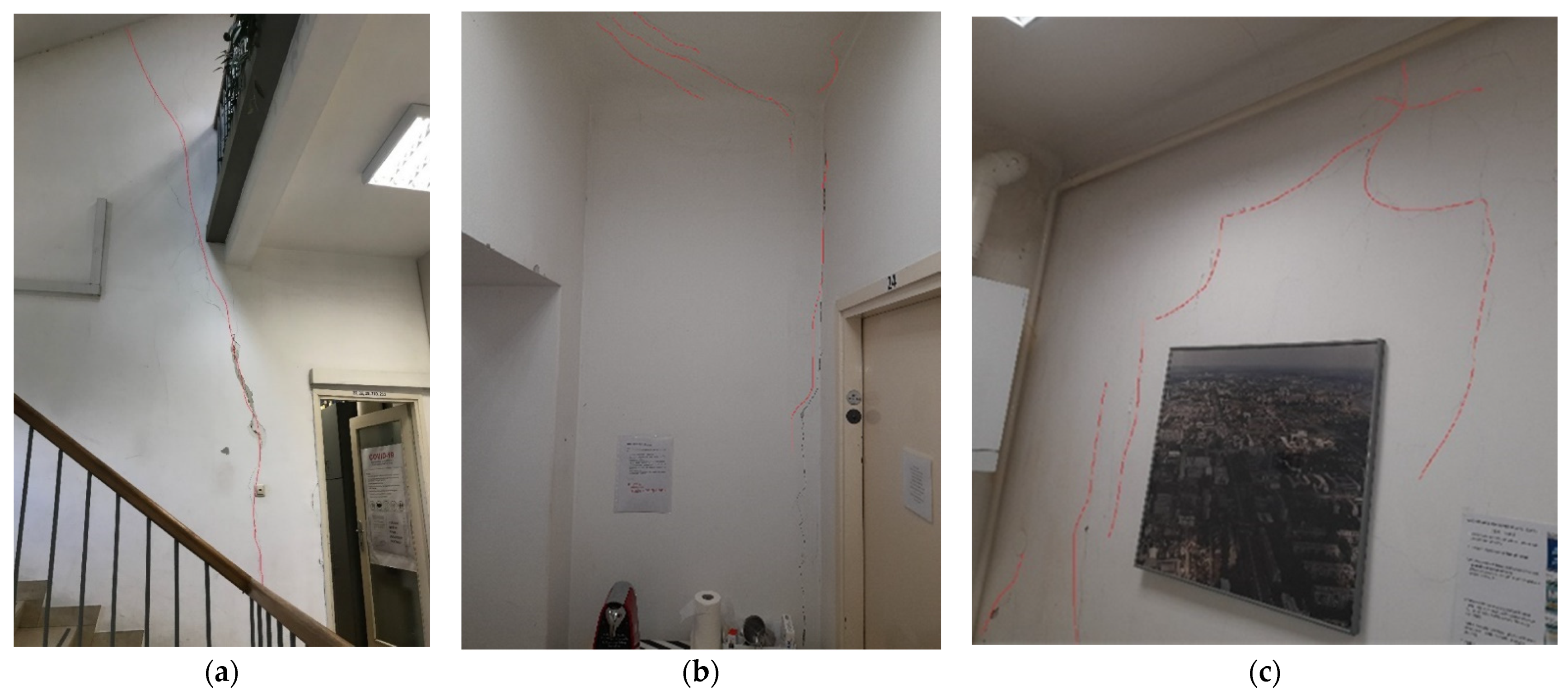
  • Several minor cracks were observed on the façades of the building. Due to their slenderness and low vertical load chimneys failed predominantly by shear sliding and overturning. Additionally, roof displacement and collision with chimneys increased failure occurrences.
  • On the ground floor, small cracks were noticed at the places of the lintel and at the connections of the walls and ceiling. Lintels are weakened parts of the masonry walls and are therefore vulnerable since the damage is usually concentrated in them.
  • On the first floor, major damage was noticed at the connection of partition and load-bearing walls and at the connection of walls and ceilings. Observed damage is not surprising because at the partition and load-bearing wall connections and wall and ceiling connections, there is a discontinuity of material and contact of different materials that have different behavior, and thus, there are different displacements that cause cracking. Often, such cracks do not pose a significant hazard.
  • The original staircase has not been preserved, and the existing staircase has minor damage that does not indicate a threat to mechanical resistance and stability.
Some of the damaged elements are shown in Figure 8.
This inspection established conservation guidelines for the repair of load-bearing and partition walls, staircases and floor structures. The façade and roof design should be preserved along, with the reparation of existing damage after conducting detailed conservation and restoration research. In addition, this paper analyzed retrofitting strategy as one of the methods to preserve the “outer look” of the building.

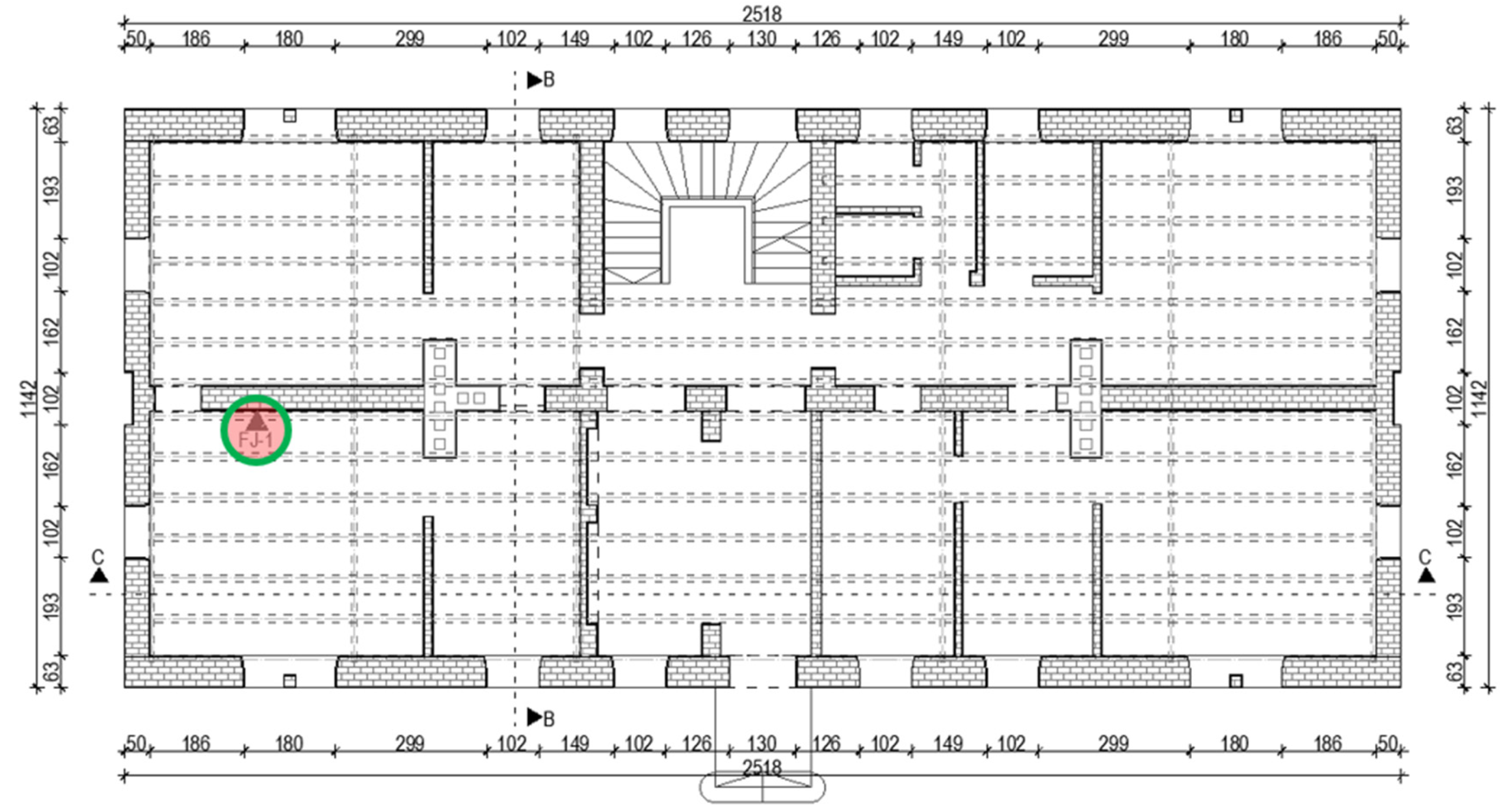
3. Condition Assessment and Moderately Destructive Testing

The flat-jack method determined the vertical stress, the modulus of elasticity and the masonry’s shear strength. The test was conducted on the ground and first floors on the same wall (Figure 9).
The procedure for testing the vertical stress of the masonry was as follows:
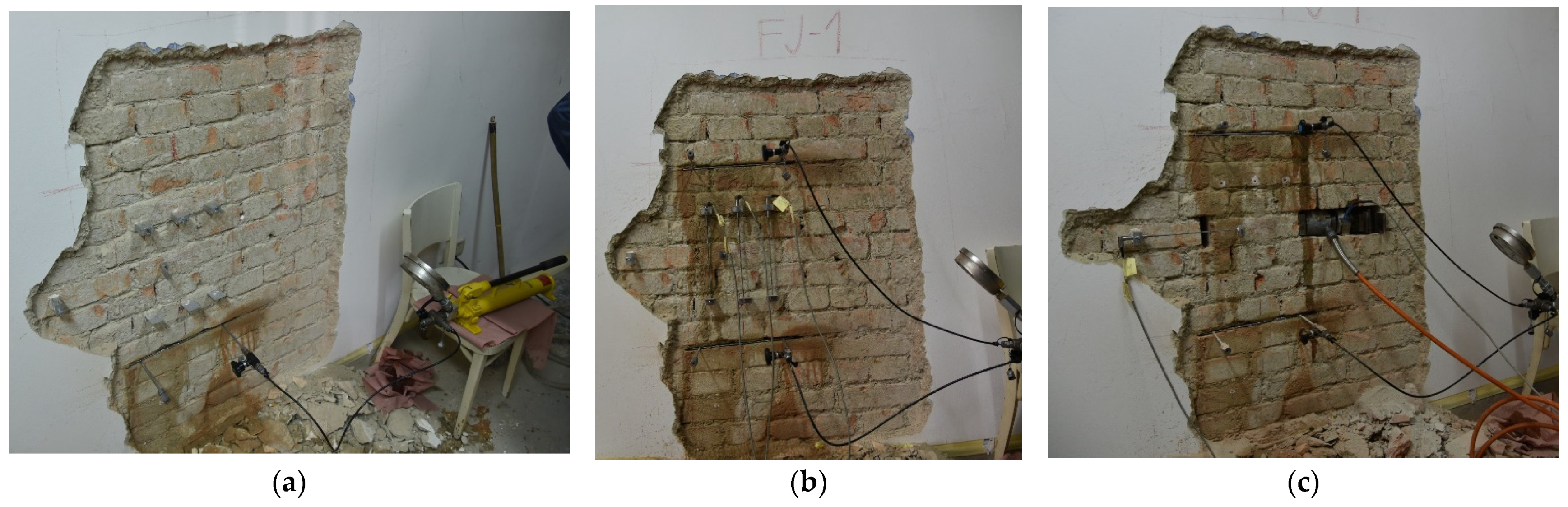
  • Removal of mortar from the horizontal joint of the masonry to partially release the masonry from compressive stress.
  • Inserting a flat jack into the hole.
  • Establishing the initial state of stress and strain by increasing the pressure in flat jacks.
It should be noted that the results obtained by this test are the average value of the masonry stress in the vicinity of the opening. Therefore, the obtained results can be assumed as representative stress for the whole tested wall when the wall is completely homogeneous, and the load is not eccentric.
The test procedure for masonry elasticity modulus was as follows:
  • The test is performed in the same place as the vertical stress test.
  • A second hole is made above the existing opening into which a flat jack is inserted.
  • Both openings are horizontal, and they are vertically spaced by 5–7 rows of bricks.
  • Inserted flat jacks are connected to one hydraulic pump.
  • Displacement and relative deformation measuring devices are placed between flat jacks.
  • Simultaneous application of vertical pressure to flat jacks and measurement of relative deformation using the device allows determining the modulus of elasticity.
The shear strength test procedure for masonry was as follows:
  • The test is performed in the same place as the test of the modulus of elasticity of the masonry.
  • One horizontal brick is removed to install the hydraulic press.
  • Mortar was removed from the vertical joint of the horizontal test brick.
  • A device for measuring displacements and relative deformations is installed over the test brick and the adjacent horizontal brick.
  • Using a hydraulic press, horizontal pressure was applied to the test brick to move.
  • Flat jacks enable the control of vertical stress to obtain the values of the coefficient of friction and the initial shear strength from the values of the ratio of shear strength and vertical stress.
The vertical stress of the masonry is determined by the following expression (ASTM C1196-14a):
σ 0 = K m · K a · p
where K m is a dimensionless coefficient depending on the geometry and stiffness of the flat jack. The calibration of the flat jack determines it. K a is a dimensionless coefficient determined from the ratio of the area of the flat jack and the area of the opening, and p is the pressure in the flat jack required to return the wall to its initial state of stress and strain.
According to the tests (Figure 10), the following values were obtained: compressive stress state in masonry at test location σ 0 = 0.46 N/mm2 (used for model calibration regarding weight distribution), modulus of elasticity E = 1469.5 N/mm2 (used for wall stiffness definition), initial shear strength fv0 = 0.323 N/mm2 (used for wall shear resistance definition) and coefficient of friction μ = 0.447.
Additionally, the so-called Masonry Quality Index (MQI) [31] was calculated. The MQI method is a simple and systematic qualitative approach appropriate for numerical estimation of the mechanical parameters of masonry. This method can be useful when in situ tests are not viable or for results validation when in situ tests are performed. More details on the mentioned method can be found in [31]. Table 1 shows the mechanical properties of masonry according to the method of MQI.
For all timber elements, the class of C22 is assumed, where the “C” letter implies softwood, e.g., spruce or pine, and the number “22” represents the major axis bending strength of timber. From the archives, it was concluded that softwood was used. The building was regularly maintained, and a value lower than the assumed (C24 or C27) was taken to be conservative. Seismic load analysis was performed according to EN 1998-1 [32] and the national annex [33]. The soil class is C, according to the latest geological research of the city of Zagreb.

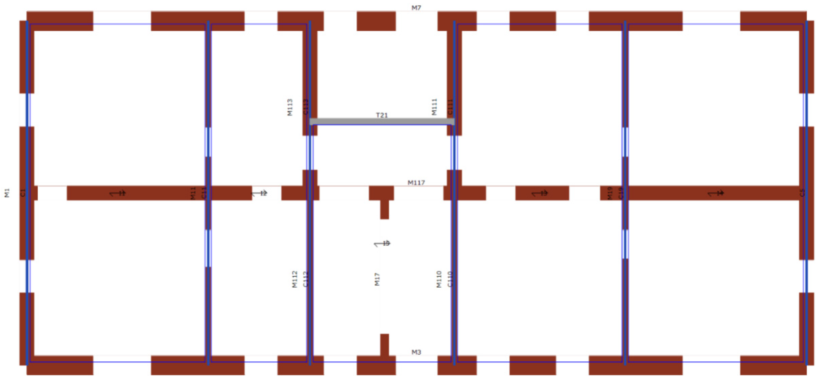
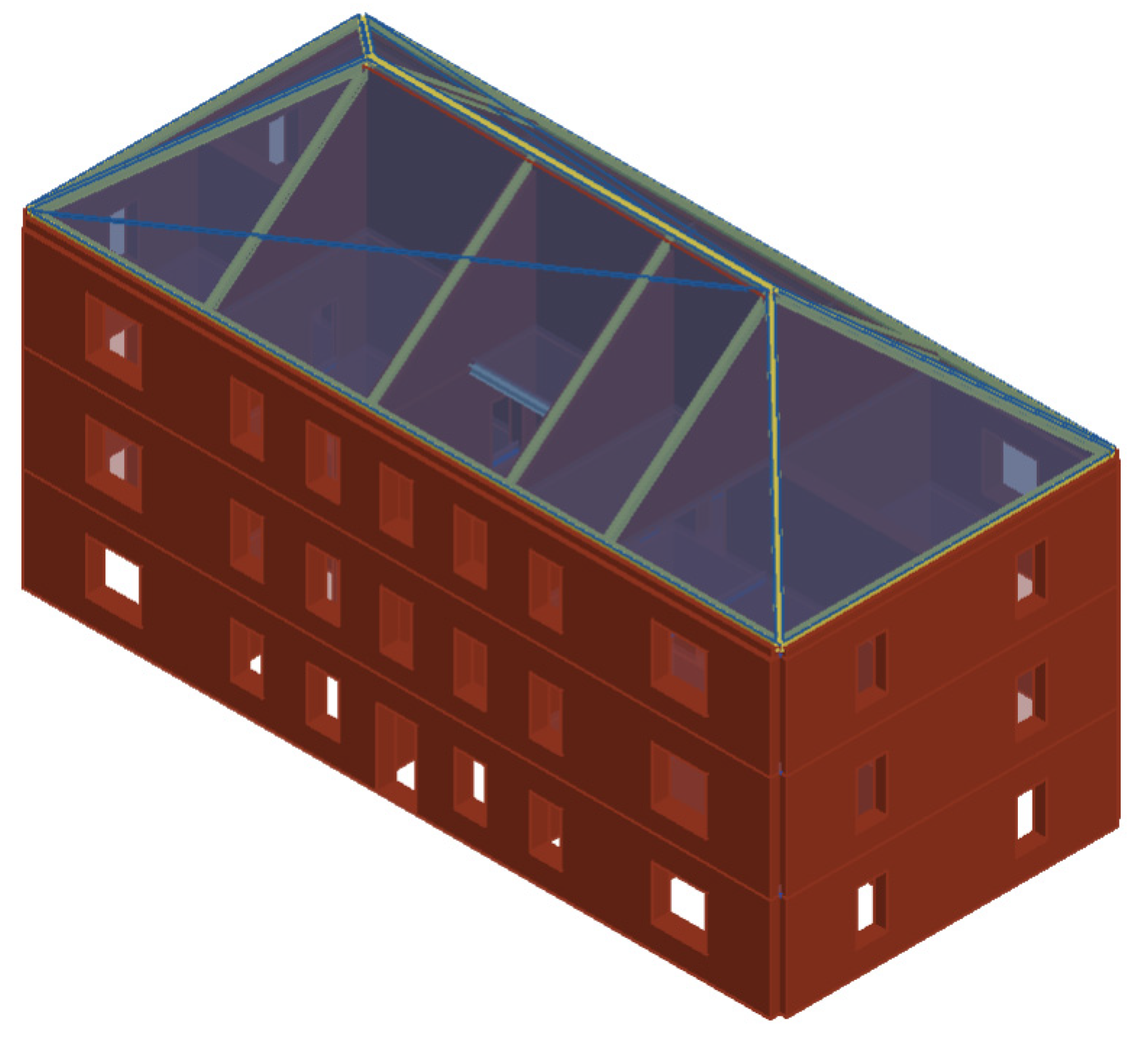
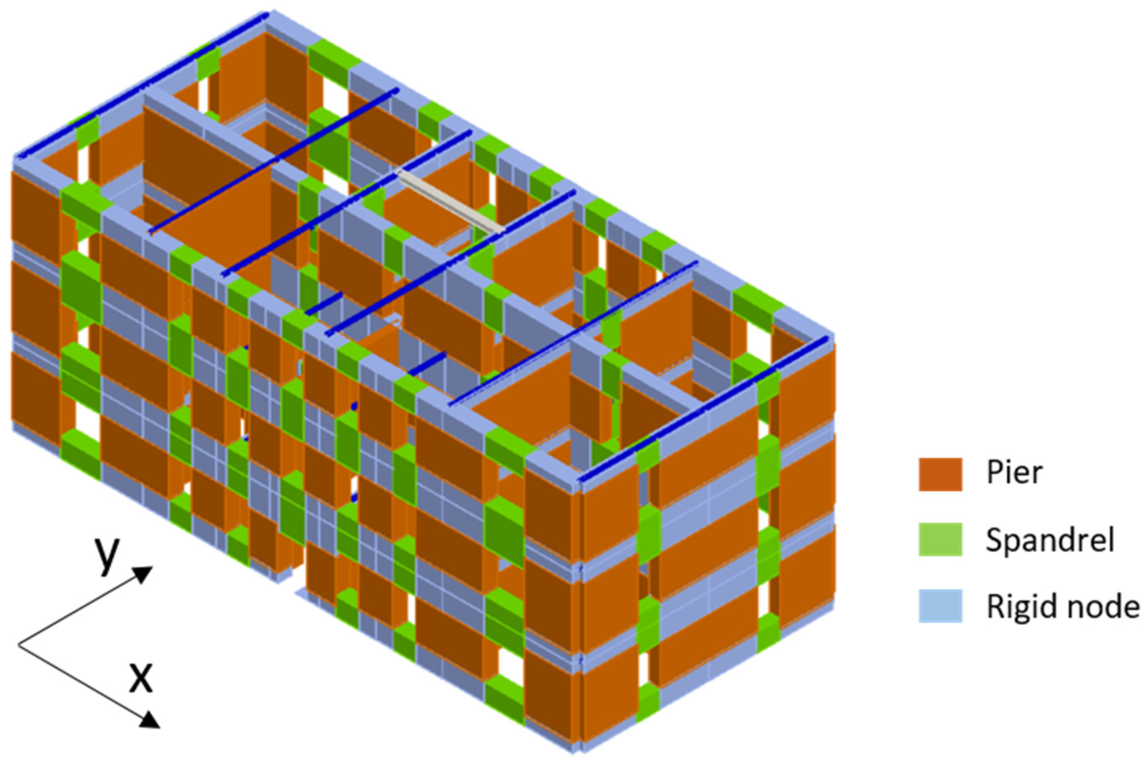
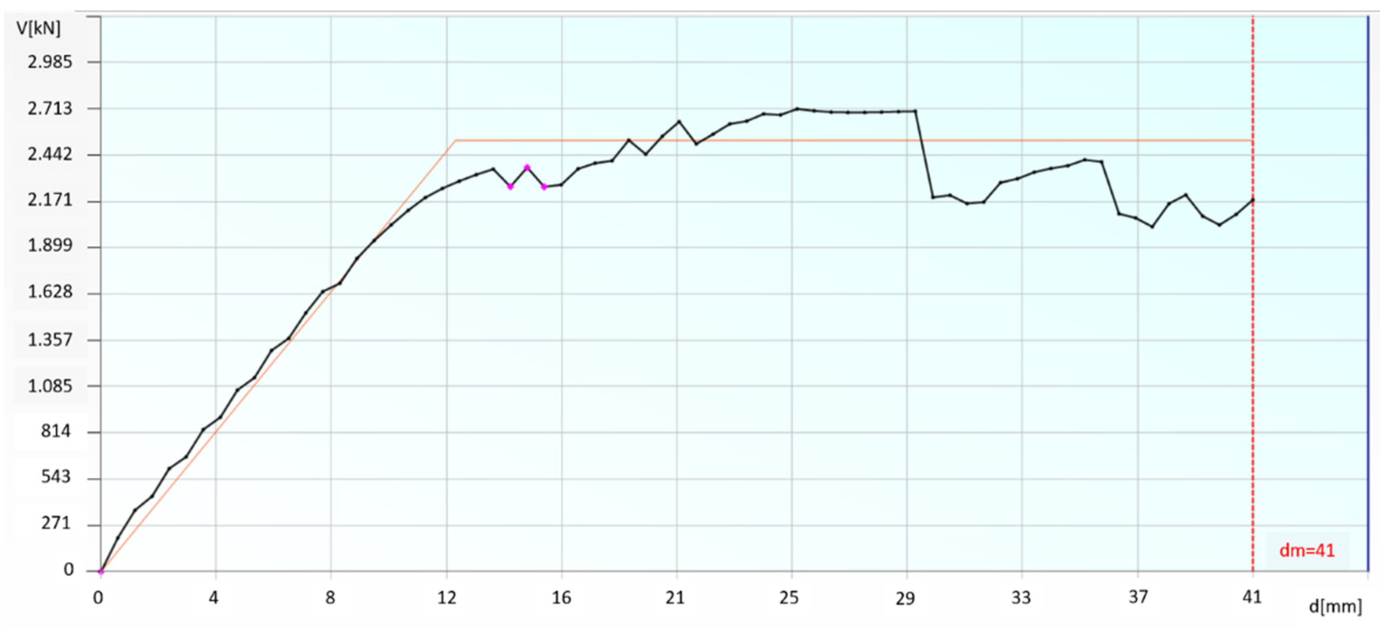
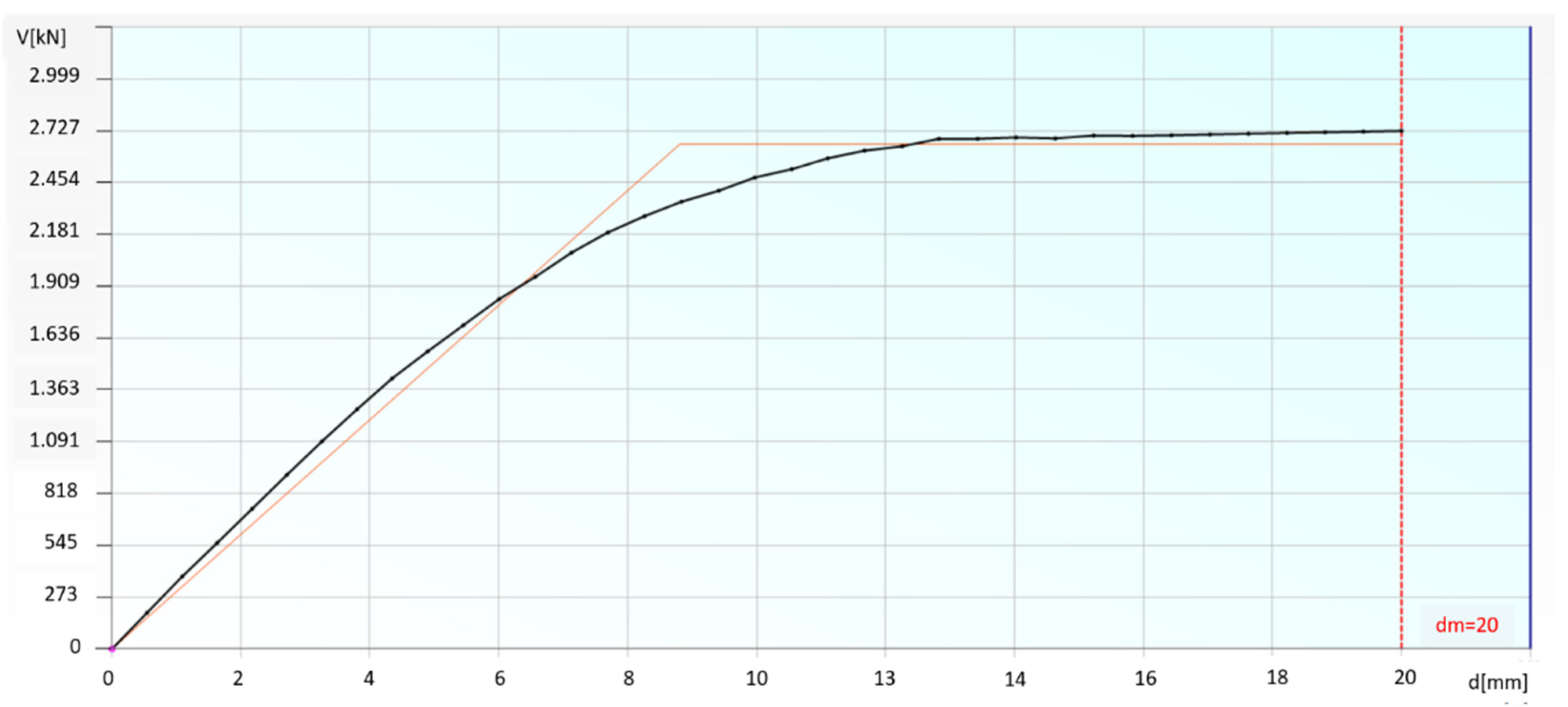
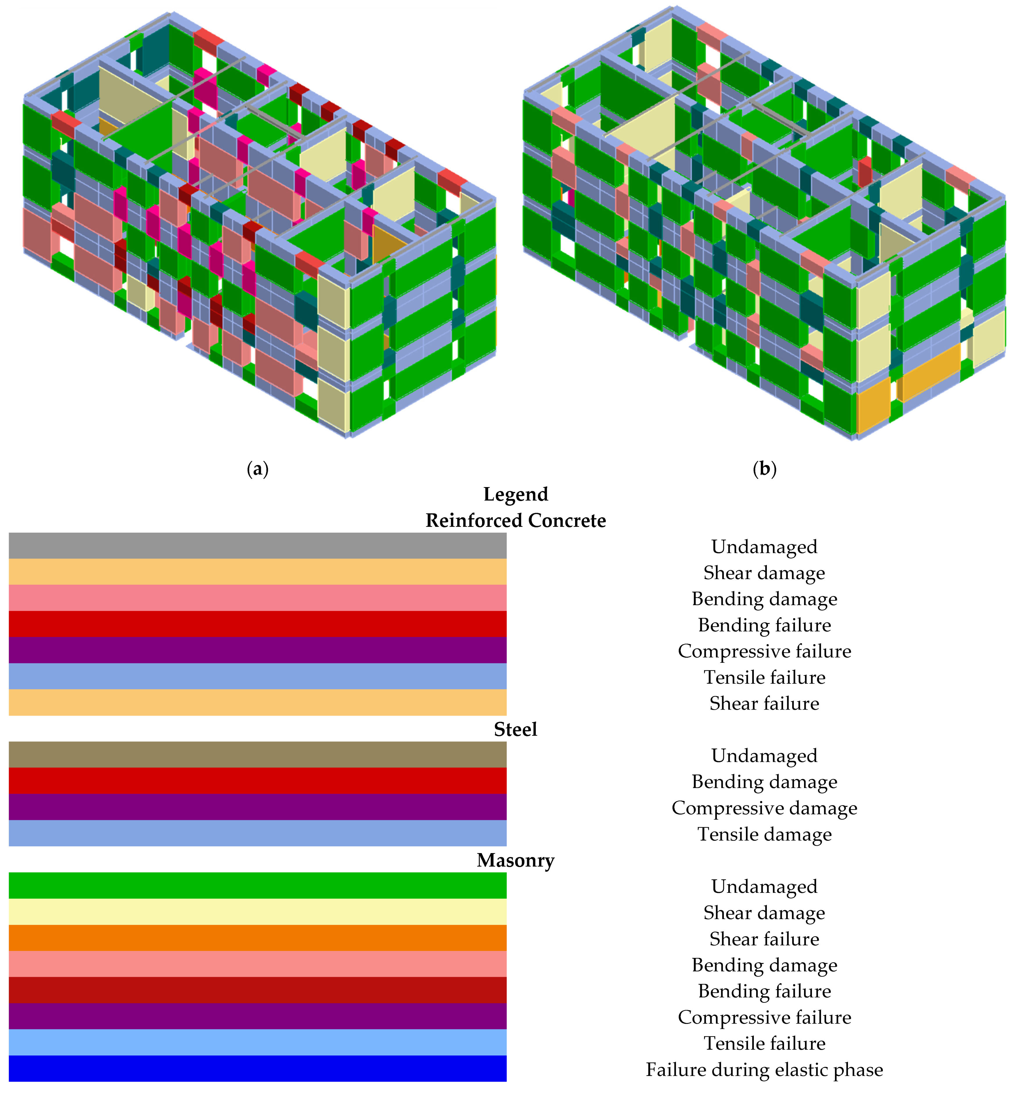
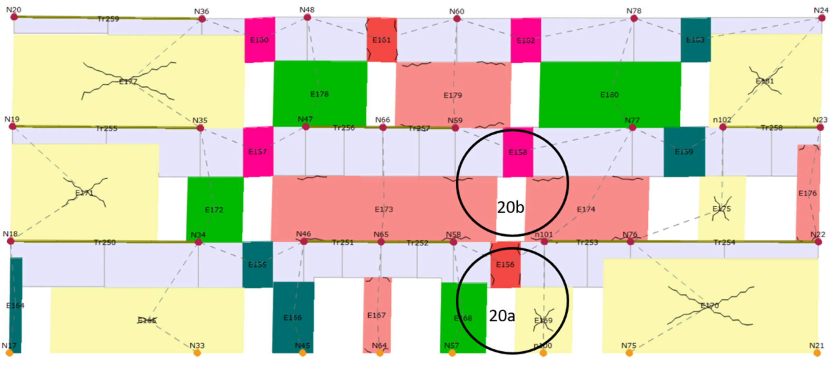
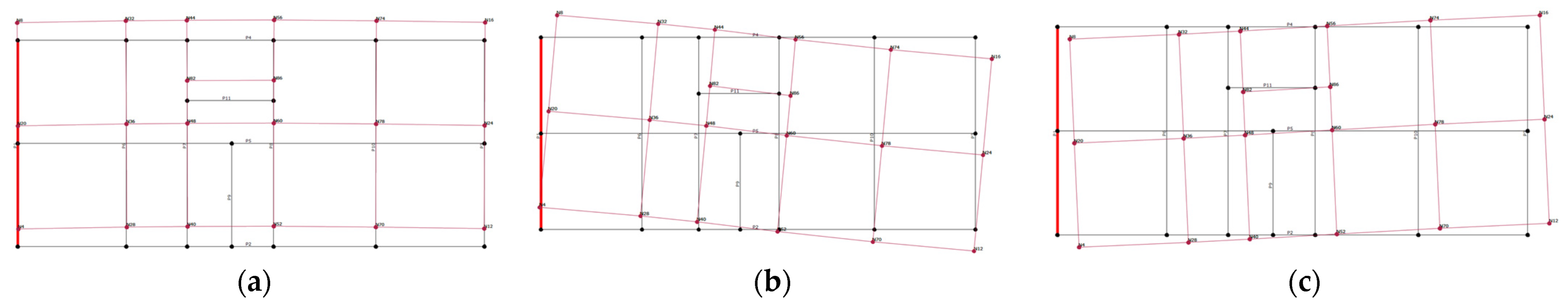
4. Numerical Modeling of the Case Study Building

The building’s choice of modeling and design method affects the accuracy and reliability of the results themselves. For example, simpler calculation methods give conservative results that can deviate greatly from the actual damage. On the other hand, more complex calculation methods give more accurate and reliable results even though they require more time. For this paper, for comparison, a seismic calculation was performed using two methods: the equivalent static load method and the pushover method. The modeling was performed using the 3Muri software.
Modeling the building in the 3Muri software is performed by inserting walls, columns and beams, which are then discretized into macroelements. There are two types of macroelements. These are the piers and spandrels in which all the damage is concentrated. Parts of the wall that are often undamaged are defined as rigid nodes, and they connect the former two [34]. The mathematical concept behind the use of macroelements makes it possible to find the mechanism of collapse, i.e., the mechanism of damage. Damage can be due to shear in the central part of the macroelements or due to combined compression and bending at the peripheral parts of the macroelements [34,35].
Horizontal diaphragms are modeled using floor elements connected by three-dimensional nodes. The loads on the horizontal diaphragms (used only for mass calculation and distribution) are perpendicular to the floor level, and the seismic action is in the direction of the floor level. For this reason, the horizontal diaphragms can be modeled as axially rigid or flexible but without bending stiffness. Such shaping of horizontal diaphragms is allowed because their main task is the acceptance of horizontal action due to seismic action and their further distribution to vertical load-bearing elements. 3Muri assumes good wall-to-wall and wall-to-floor connections, i.e., box behavior that is desirable but often unrealistic in the existing structures. Hence, during the modeling itself, it is assumed that the damaged masonry was restored to its original undamaged state by methods such as grouting and that the necessary measures were taken to ensure the box behavior of the observed structure. Good connection of walls and floors can be achieved by adding ties and anchors, as well as stiffening the floor structure. Additionally, 3Muri allows out-of-plane failure analysis of local mechanisms in a separate module. This is extremely useful since box behavior can accommodate only in-plane failure of the masonry. More on the analysis of local mechanisms in 3Muri can be found in [2].
Figure 11 shows the ground floor plan, and Figure 12 shows a 3D model of the building. Again, the floor plans of the floors roughly coincide, except that sometimes the layout of the partition walls is different.
Table 2 shows the legend of the material used to model the building.
Seismic action is determined by the equivalent static load method. To be able to apply the method of equivalent static load, the basic period of the first mode shape must be less than or equal to 4 · T C (TC = 0.6 s for soil type C) and 2   s so that it satisfies the criterion of regularity in the vertical section. Therefore, the basic period of the first mode shape is 0.29, and the building satisfies the regularity criterion in the vertical section. The first mode shape was calculated by the following expression:
T 1 = C t · H 3 4
where Ct is a coefficient dependent on the structural system, and H is the building’s height.
For the building in question, the importance class of II has been determined according to EN 1998. Importance class II corresponds to regular buildings.
Figure 13 shows the values of peak ground acceleration for the location of the building.
For old unconfined masonry, the value of the behavior factor is set as q = 1.00 . Seismic base shear force for each horizontal direction can be determined by the following expression:
F b = S d ( T 1 ) · m · λ
where Sd(T1) is spectral acceleration for the first period of the building for the observed direction, m is the building’s mass and λ is a correction factor dependent on the building’s height. The values of the design spectrum and base shear force are given in Table 3.
According to the EN 1998-1, depending on the local seismic hazard and the number of stories of the observed building, the minimum percentages of the cross-sectional area of the load-bearing walls in relation to the total floor area are given for the x- and y-directions (3% in our case). This check is the first step to establish the state of the existing building in terms of meeting the basic requirement used in the new building design process and to see if new walls should be added. Therefore, load-bearing walls in both directions meet the requirement of a minimum total area of load-bearing walls for simple masonry buildings (x = 7.79%, y = 4.20%).
For the design purposes, the following mechanical characteristics and coefficients are taken based on in situ tests, code recommendations and literature review:
  • Partial safety factor, γ M = 1.50 .
  • Modulus of elasticity E = 1470   N / mm 2
  • Initial shear strength of masonry obtained from in situ testing, f v 0 = 0.323   N / mm 2 .
  • Confidence factor value, F P = 1.20 according to knowledge level 2.
  • Diagonal tensile strength of masonry, f t = 0.114   N / mm 2 .
  • Local coefficient of friction of the joint, μ j = 0.60 .
  • Clamping coefficient, ϕ = 1.00 .
  • Mean compressive strength of the units, f b = 12.00   N / mm 2 .
  • Value for clay unit from group 1 and general-purpose mortar, K = 0.55 .
  • Mortar compressive strength, f m o r t a r = 1.50   N / mm 2 .
The confidence factor is used to determine the seismic design method and depends on the level of knowledge. To determine the level of knowledge, it is necessary to know the geometric relationships of the structural and nonstructural elements, details (masonry, the connection of floor structure and masonry, etc.) and mechanical properties of the material from which the structure is built.
Suppose the level of knowledge is determined to be 1. In that case, the typical values of the mechanical characteristics of the material are assumed following the construction time of the building, and the structural tests are limited. If the level of knowledge is 2, then the values of mechanical characteristics of the material are assumed according to the original design specification or according to the values obtained from extensive research. The level of knowledge 2 was taken for the case study. Calculated base shear force is distributed on each floor, increasing linearly, along the height of the building. Next, floor forces are further distributed to walls according to their stiffnesses. To derive capacity utilization, i.e., the ratio of capacity and demand of individual walls, the resistance of the walls is compared with distributed wall forces. For global verification, the sum of the resistances of all the ground floor walls in the same direction was compared with total base shear force. According to the manual calculation (lateral force method), the capacity/demand ratio in the x-direction was 0.92, and in the y-direction 0.44. Masonry can fail in several different modes. Hence, the resistance to bending, shear sliding and diagonal tension failure (straight and stepped) are calculated. Expressions for resistance calculation can be found in [7]. According to the calculation of the masonry resistance, the load-bearing capacity of the walls in the x- and y-directions is not sufficient to absorb the earthquake force of the return period of 95 years. Therefore, adding walls (or an equivalent system for absorbing horizontal forces) in both directions is necessary.
The 3Muri software has a module for conducting modal analysis. This module offers the calculation of all possible mode shapes. In this paper, 10 mode shapes are considered, and 3 are shown in Figure 14 and in Table 4. The first and third modes are predominantly translational, while in the second mode, slight torsion occurs.
The pushover method in the 3Muri software is carried out depending on the distribution of lateral load on the structure. The lateral load distribution can be linearly increasing or uniform along the height of the building or in the form of the translational mode shape. Figure 15 shows a 3D model of the equivalent frames of the building developed in the 3Muri software. Four analyses were performed for the modal lateral load distribution, two in the x-direction (+X and −X) and two in the y-direction (+Y and −Y). Figure 16 and Figure 17 show the capacity curves in the x- and y-directions (black) and their bilinear idealization (orange). Value “dm” on the graph represents the near-collapse limit state. It is reached when the maximum value of the shear force drops by 20%. Figure 18 shows a 3D model with damage to the near-collapse limit state for critical analysis in the x- and y-directions.
The pushover analysis was performed for all three distributions of lateral load without random eccentricity. Finally, the capacity/demand ratio obtained according to the simplified calculations and the values of the safety indices for critical analyses obtained using the 3Muri software were compared, as shown in Table 5. According to the regulation, the safety index is the ratio of peak ground acceleration for which the structure reaches a certain limit state, i.e., capacity and peak ground acceleration (PGA), i.e., demand. PGA for a return period of 95 years was used, and it has a value of 0.13 g. The limit state of significant damage (SD) was observed.
According to the above, the simplified calculation visibly deviates from the calculation using the 3Muri software for calculating the capacity/demand ratio in the y-direction. The visible deviation occurred because the simplified calculation method has more geometric limitations due to the choice of the walls, such as the minimum wall thickness and the minimum wall length to height ratio. Thus, not all walls were considered when choosing load-bearing walls. Additionally, in the 3Muri software, in addition to partition walls, concrete and steel beams are modeled, contributing to the rigidity of the entire building, but mostly in the y-direction as can be seen in Figure 15 (steel beams in blue). Therefore, it can be concluded that the simplified design is more conservative for the y-direction compared to the design in the 3Muri software, which was expected. In the other direction, results are more similar, but the more conservative design is now reversed in favor of the 3Muri software.
To compare the actual damage and the damage obtained using the 3Muri software, a uniform lateral load distribution was selected. It is assumed that the peak ground acceleration of the earthquake in Zagreb in 2020 was about 0.18 g. The results of damage are shown in Figure 19, with locations of real damage shown in Figure 20a,b.
Figure 20a shows the actual damage to the right part of the load-bearing wall on the ground floor corresponding to the shear damage. Figure 20b shows the actual damage to the middle part of the load-bearing wall on the first floor, which corresponds to the damage due to bending. Similar damage is detected in height in the building itself, and damage corresponds to the model.

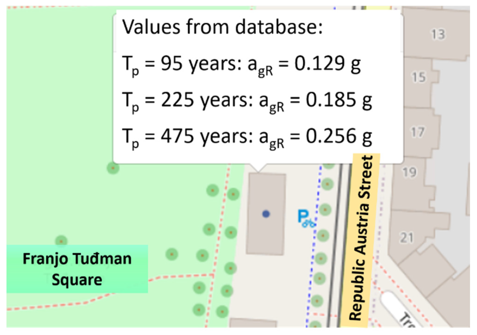
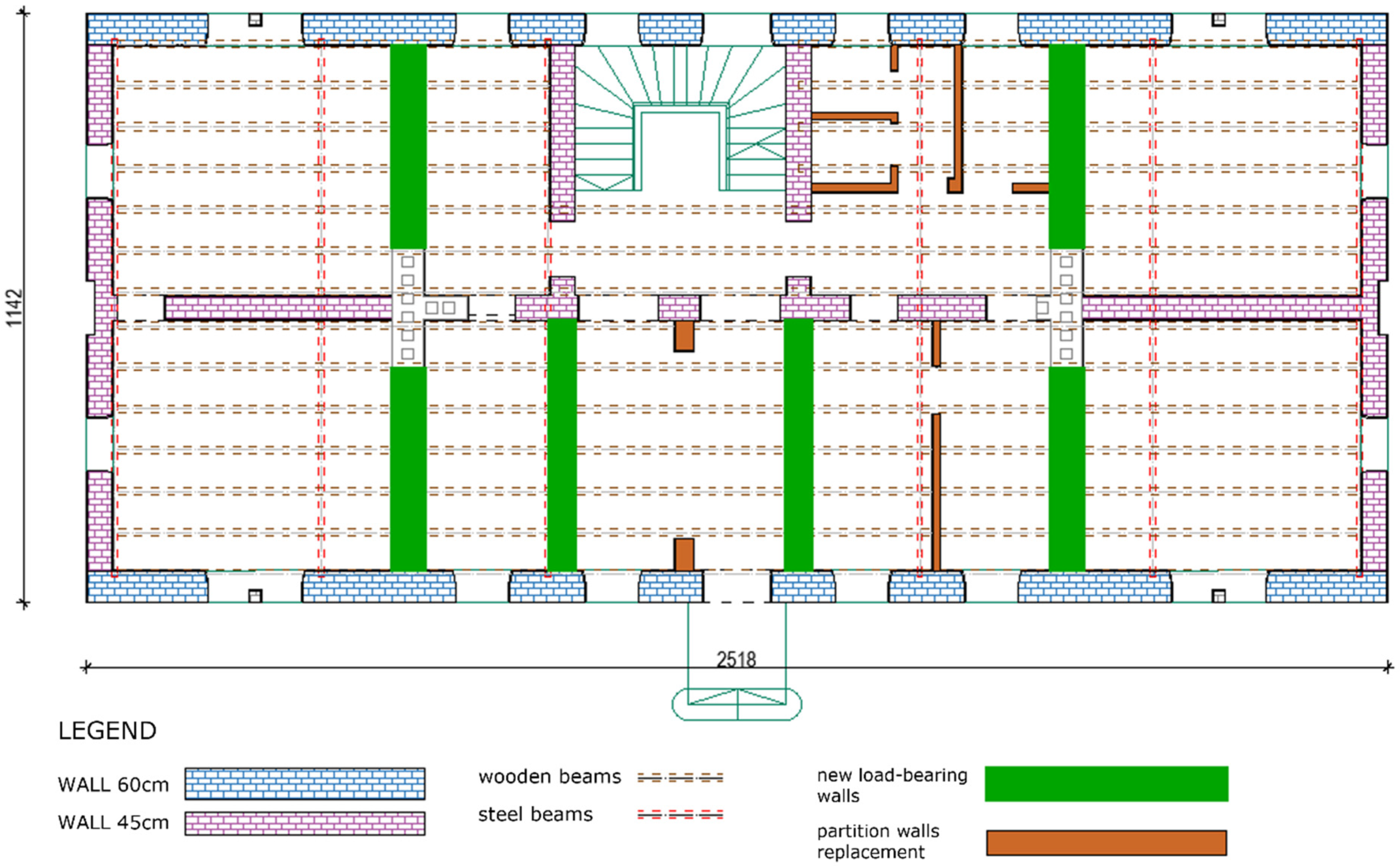
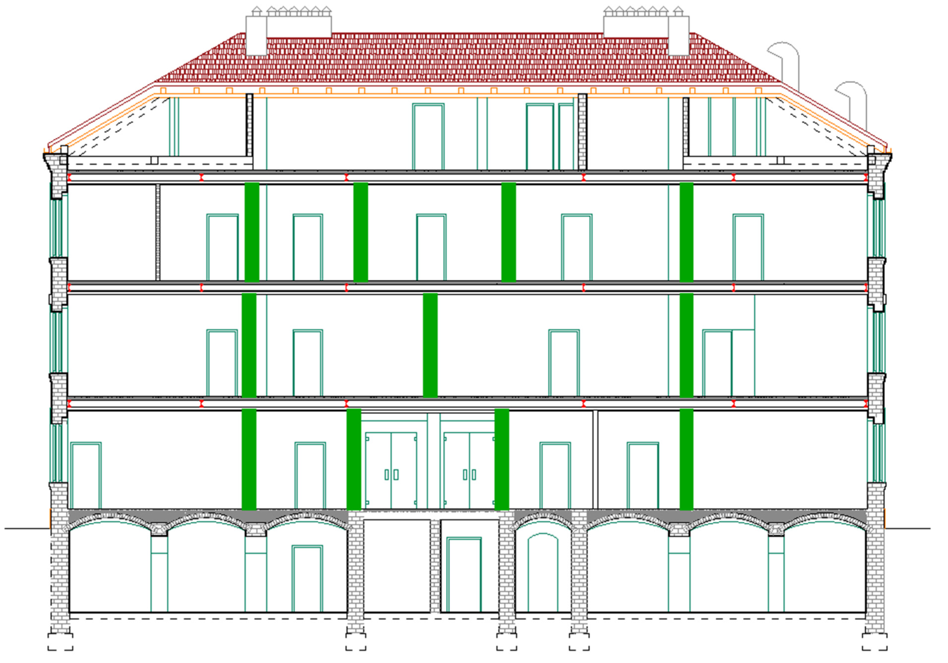
5. Renovation Measures for Existing Masonry Buildings after the Earthquake(s) in Croatia

For the successful renovation of buildings damaged in the earthquake, it is necessary to apply appropriate measures for repair and strengthening of the building without compromising the mechanical characteristics of the material and the properties of the structure that contribute to the durability of the building [37].
After the earthquakes in Croatia, to create a legal framework for the faster, economical and easier reconstruction of earthquake-damaged areas, the Law on Reconstruction of Earthquake-Damaged Buildings in the city of Zagreb, Krapina-Zagorje County and Zagreb County [38] was passed. The Law defines the methods of reconstruction that depend on the degree of damage and purpose of the building. Additionally, an addendum to the technical regulations was issued [39], which defines the levels of renovation, which are:
  • Level 1: repair of nonstructural elements.
  • Level 2: structural repair to the return period of 95 years.
  • Level 3: strengthening to the return period of 225 years.
  • Level 4: Complete retrofitting to the return period of 475 years.
The Technical Regulation [39] defines the requirements, documentation, interventions and works, and the category of buildings that the renovated structure must meet for each level above. A proposal of measures for repair and reinforcement of buildings is given following the obtained results. Measures should follow the seismic design and be in line with the conservation and restoration rules. The minimum restoration level is level 2 for all structures with greater damage. However, in addition to the proposed minimum level of renovation, the building owner may request renovation to a higher level than the prescribed level of renovation at his own expense. For the building in question, the proposed level of renovation is level 2, but at the request of the owner of the building, renovation level 3 is selected.
As a measure of repair and reinforcement of the walls of the building, it is recommended to reinforce load-bearing walls by, e.g., FRCM system or concrete jacketing. Figure 21 shows a proposal for reinforcing load-bearing walls. To obtain good resistance in the transverse direction (y-direction), it is proposed to add new load-bearing walls with a minimum thickness of 38 cm. In addition, it is proposed to remove the brick partition walls and replace them with a drywall system. Figure 22 and Figure 23 show a proposal for the position of the new load-bearing walls and a proposal for the removal and replacement of partition walls.
In addition to mentioned methods, it is necessary to strengthen the ceiling structure. Therefore, as a measure of repair and reinforcement of the wooden ceiling structure, a thin reinforced concrete compression slab is proposed to increase the load-bearing capacity and stiffen the structure (rigid diaphragm). All arched elements, vaults in the basement are planned to be kept in the original design with the possibility of strengthening with carbon fibers, maintaining the original proportion of the vaults in order to preserve the original construction and design characteristics of the building.
Additionally, this paper analyzed the possibility to perform an equivalent system for an alternative retrofitting strategy to take over horizontal forces. An example of an idea for an equivalent system for taking over horizontal forces can be found in Figure 24. The idea of an equivalent system for taking over horizontal forces consists of using existing steel beams (crossbeams) in the floor structure. New steel beams would be added to the existing steel beams, which would end outside the structure itself. The new steel beams would be externally connected to the steel rope, as shown in Figure 24. Bracing elements could be placed to ensure the common behavior of the whole system and the building and ensure sufficient transverse stiffness.
This approach allows a clear differentiation of the old structure and the new-seismic one. The old structure becomes easier to read and more visible, due to the fact that the new seismic elements are mostly connected to the existing one and thus in some way additionally mark it. They also damage it less since no drastic interventions are needed for their installation or execution.
The proposed solution gives freedom in a case where interventions cannot be obtained from the interior. The existing horizontal frames steel beams can efficiently be connected to the exterior bracing system and throughout those beams transfer horizontal forces. In that way, the interior design can be saved, and the layout can be pretty much intact. The exterior vertical bracing system with a tension diagonal in general has a good dynamic response with the unreinforced masonry building, as those lateral systems are not too stiff as for example shear walls from omitted masonry or RC. This example can be also used for educational purposes to provide different solutions and different aspects in seismic retrofitting.
Another possible renovation method, i.e., seismic isolation, is used for the rehabilitation of buildings of special cultural and historical importance. The building should be separated from the ground, thus constructing new foundations on which insulating units are placed, and on them a new construction that will transfer loads from the existing building to the insulators. In addition, the biggest advantage of seismic insulation as a remedial measure is that the building does not require additional interventions and elements that could damage the façade or interior. This method is, on the other hand, considerably more expensive than others.

6. Conclusions

The Republic of Croatia is one of the most seismically endangered countries in Europe, especially the Mediterranean area and northwestern Croatia. However, the city of Zagreb is a seismically active area due to the Žumberak-Medvednica fault and the Zagreb fault, which consists of a series of smaller faults. After the two earthquakes in Croatia, about 70,000 buildings were damaged, 25,000 in the Zagreb earthquake and about 45,000 in an earthquake whose epicenter was 70 km from Zagreb.
Most of the damaged buildings are of an older date of construction, mostly built in the period before the existence of the first earthquake regulations, and are built of brick with wooden floor structures. Such structures are characterized by uneven stiffness distribution, inappropriate or nonexistent connections between the walls and poor connection to the roof and floor structure. Many of these buildings are under cultural heritage protection, and such an example is the building presented in this paper.
The building was fully inspected after the earthquake by engineers in accordance with a pre-established methodology (EMS-98). Subsequently, for further potential restoration work, a digital “twin” of the building has been created with the Leica BLK360 device. Laser scanning resulted in a point cloud with a precision of 3 mm, which was processed in the Cyclone Register 360 software. This way, the original façade with external geometric contours and details was preserved for the future. Additionally, on-site investigative and moderately destructive tests were carried out using the flat-jack system. The tests provided an important insight into the material characteristics such as modulus of elasticity, compressive stress state, coefficient of friction and initial shear strength without the contribution of vertical stress, which are required for modeling. Since the standards recommend nonlinear methods of analysis for existing masonry structures, the pushover method integrated into the 3Muri program was used. Several different vertical distributions of seismic loads were considered. In addition, simplified manual calculations were performed. Finally, all methods were compared, where a significant deviation of the results of the manual method was observed.
The results obtained using the 3Muri software and the simplified method show that the case study building does not meet the states of limited damage, significant damage and near collapse, with return periods of 95 years, 225 years and 475 years. Therefore, in addition to the condition assessment and seismic design of the structure, a proposal of measures for repairs and strengthening of the structure was given in accordance with applicable laws and new regulations.
When designing a technical solution for the renovation and reinforcement of seismic resistance of the protected heritage building, it is necessary to envisage strengthening methods that are minimally invasive for historic structures and space utilization, using appropriate materials and methods, to enable preservation and presentation of original exterior and interior building characteristics.
In the process of strengthening, it is necessary to integrate and enhance the energy efficiency of the structure, as well as to preserve the architectural and historical values of the protected heritage while ensuring the safe and functional use of the building. Aseismic measures, elements whether exposed, visible or not, should respect the character and integrity of the cultural heritage and be visually in harmony with it. The seismic system should be reversible as much as possible so that it can be replaced by more advanced seismic measures in the future.

Author Contributions

Conceptualization, M.S.; methodology, M.M. and M.S.; software, M.M., B.Č.Š. and L.L.; validation, M.S., I.M. and L.L.; formal analysis, M.M., N.I., B.Č.Š. and L.L.; investigation, M.M. and N.I.; resources, M.S., I.M. and N.I.; data curation, M.M., N.I., B.Č.Š., L.L. and M.S.; writing—original draft preparation, M.S. and M.M.; writing—review and editing, M.S., Y.E., N.I., B.Č.Š. and I.M.; visualization, M.M., N.I. and M.S.; supervision, M.S., I.M. and Y.E.; project administration, M.S. and N.I.; funding acquisition, M.S. All authors have read and agreed to the published version of the manuscript.

Funding

This research was funded by the Croatian Science Foundation, grant number UIP-2019-04-3749 (ARES project—Assessment and rehabilitation of existing structures—development of contemporary methods for masonry and timber structures), project leader: Mislav Stepinac.

Data Availability Statement

All of the data shown in the paper, from laser scanning, visual inspection, non-destructive testing to structural modeling and strengthening proposals, was done by the authors. The data presented in this study are available on request from the corresponding author. The data are not publicly available due to privacy reasons.

Conflicts of Interest

The authors declare no conflict of interest.

References

  1. World Bank Report: Croatia Earthquake–Rapid Damage And Needs Assessment, 2020, June 2020; Government of Croatia: Zagreb, Croatia, 2020.
  2. Lulić, L.; Ožić, K.; Kišiček, T.; Hafner, I.; Stepinac, M. Post-Earthquake Damage Assessment-Case Study of the Educational Building after the Zagreb Earthquake. Sustainability 2021, 13, 6353. [Google Scholar] [CrossRef]
  3. Saloustros, S.; Pelà, L.; Contrafatto, F.R.; Roca, P.; Petromichelakis, I. Analytical Derivation of Seismic Fragility Curves for Historical Masonry Structures Based on Stochastic Analysis of Uncertain Material Parameters. Int. J. Archit. Herit. 2019, 13, 1142–1164. [Google Scholar] [CrossRef]
  4. Stepinac, M.; Kisicek, T.; Renić, T.; Hafner, I.; Bedon, C. Methods for the Assessment of Critical Properties in Existing Masonry Structures under Seismic Loads-the ARES Project. Appl. Sci. 2020, 10, 1576. [Google Scholar] [CrossRef] [Green Version]
  5. Stepinac, M.; Lourenço, P.B.; Atalić, J.; Kišiček, T.; Uroš, M.; Baniček, M.; Šavor Novak, M. Damage Classification of Residential Buildings in Historical Downtown after the ML5.5 Earthquake in Zagreb, Croatia in 2020. Int. J. Disaster Risk Reduct. 2021, 56, 102140. [Google Scholar] [CrossRef]
  6. Novak, M.Š.; Uroš, M.; Atalić, J.; Herak, M.; Demšić, M.; Baniček, M.; Lazarević, D.; Bijelić, N.; Crnogorac, M.; Todorić, M. Zagreb Earthquake of 22 March 2020–Preliminary Report on Seismologic Aspects and Damage to Buildings. Gradjevinar 2020, 72, 843–867. [Google Scholar] [CrossRef]
  7. Kišiček, T.; Stepinac, M.; Renić, T.; Hafner, I.; Lulić, L. Strengthening of Masonry Walls with FRP or TRM. Gradjevinar 2020, 72, 937–953. [Google Scholar] [CrossRef]
  8. The Database of Usability Classification, Croatian Centre of Earthquake Engineering (HCPI-Hrvatski Centar Za Potresno Inženjerstvo); Faculty of Civil Engineering, University of Zagreb and The City of Zagreb: Zagreb, Croatia, 2020.
  9. Forsyth, M. Structures and Construction in Historic Building Conservation; Blackwell Publishing Ltd.: Hoboken, NJ, USA, 2008. [Google Scholar] [CrossRef]
  10. Vlachakis, G.; Vlachaki, E.; Lourenço, P.B. Learning from Failure: Damage and Failure of Masonry Structures, after the 2017 Lesvos Earthquake (Greece). Eng. Fail. Anal. 2020, 117, 104803. [Google Scholar] [CrossRef]
  11. Cruz, H.; Yeomans, D.; Tsakanika, E.; Macchioni, N.; Jorissen, A.; Touza, M.; Mannucci, M.; Lourenço, P.B. Guidelines for On-Site Assessment of Historic Timber Structures. Int. J. Archit. Herit. 2015, 9, 277–289. [Google Scholar] [CrossRef]
  12. Sánchez Rodríguez, A.; Riveiro Rodríguez, B.; Soilán Rodríguez, M.; Arias Sánchez, P. Laser Scanning and Its Applications to Damage Detection and Monitoring in Masonry Structures. In Long-Term Performance and Durability of Masonry Structures. Degradation Mechanisms. Health Monitoring and Service Life Design; Ghiassi, B., Lourenço, P.B., Eds.; Woodhead Publishing: Cambridge, UK, 2019; pp. 265–285. [Google Scholar] [CrossRef]
  13. Funari, M.F.; Mehrotra, A.; Lourenço, P.B. A Tool for the Rapid Seismic Assessment of Historic Masonry Structures Based on Limit Analysis Optimisation and Rocking Dynamics. Appl. Sci. 2021, 11, 942. [Google Scholar] [CrossRef]
  14. Endo, Y.; Pelà, L.; Roca, P. Review of Different Pushover Analysis Methods Applied to Masonry Buildings and Comparison with Nonlinear Dynamic Analysis. J. Earthq. Eng. 2017, 21, 1234–1255. [Google Scholar] [CrossRef] [Green Version]
  15. Ortega, J.; Vasconcelos, G.; Rodrigues, H.; Correia, M. Assessment of the Influence of Horizontal Diaphragms on the Seismic Performance of Vernacular Buildings. Bull. Earthq. Eng. 2018, 16, 3871–3904. [Google Scholar] [CrossRef]
  16. Stepinac, M.; Rajčić, V.; Barbalić, J. Inspection and Condition Assessment of Existing Timber Structures. Gradjevinar 2017, 69, 861–873. [Google Scholar] [CrossRef] [Green Version]
  17. Fortunato, G.; Funari, M.F.; Lonetti, P. Survey and Seismic Vulnerability Assessment of the Baptistery of San Giovanni in Tumba (Italy). J. Cult. Herit. 2017, 26, 64–78. [Google Scholar] [CrossRef]
  18. Malcata, M.; Ponte, M.; Tiberti, S.; Bento, R.; Milani, G. Failure Analysis of a Portuguese Cultural Heritage Masterpiece: Bonet Building in Sintra. Eng. Fail. Anal. 2020, 115, 104636. [Google Scholar] [CrossRef]
  19. CIB 335. Guide for the Structural Rehabilitation of Heritage Buildings; CIB Commission W023: Ottawa, ON, Canada, 2010. [Google Scholar]
  20. Lourenço, P.B. Conservation of Cultural Heritage Buildings: Methodology and Application to Case Studies. Rev. ALCONPAT 2013, 3, 98–110. [Google Scholar] [CrossRef] [Green Version]
  21. Betti, M.; Bonora, V.; Galano, L.; Pellis, E.; Tucci, G.; Vignoli, A. An Integrated Geometric and Material Survey for the Conservation of Heritage Masonry Structures. Heritage 2021, 4, 585–611. [Google Scholar] [CrossRef]
  22. Stepinac, M.; Gašparović, M. A Review of Emerging Technologies for an Assessment of Safety and Seismic Vulnerability and Damage Detection of Existing Masonry Structures. Appl. Sci. 2020, 10, 5060. [Google Scholar] [CrossRef]
  23. Ortega, J.; Vasconcelos, G.; Rodrigues, H.; Correia, M. Seismic Vulnerability and Loss Assessment of Vila Real de Santo António, Portugal: Application of a Novel Method. Int. J. Archit. Herit. 2020, 15, 1585–1607. [Google Scholar] [CrossRef]
  24. Saloustros, S.; Pelà, L.; Roca, P.; Portal, J. Numerical Analysis of Structural Damage in the Church of the Poblet Monastery. Eng. Fail. Anal. 2015, 48, 41–61. [Google Scholar] [CrossRef]
  25. Giordano, E.; Ferrante, A.; Clementi, F.; Milani, G.; Formisano, A. Cultural Heritage and Earthquake: The Case Study of San Francesco’s Church in Amandola (Central Italy). In Proceedings of the 2019 IMEKO TC4 International Conference on Metrology for Archaeology and Cultural Heritage, MetroArchaeo 2019, Florence, Italy, 4–6 December 2019. [Google Scholar]
  26. Formisano, A.; Vaiano, G.; Fabbrocino, F. A Seismic-Energetic-Economic Combined Procedure for Retrofitting Residential Buildings: A Case Study in the Province of Avellino (Italy). In AIP Conference Proceedings; AIP Publishing LLC: Melville, NY, USA, 2019. [Google Scholar] [CrossRef]
  27. Capanna, I.; Aloisio, A.; Di Fabio, F.; Fragiacomo, M. Sensitivity Assessment of the Seismic Response of a Masonry Palace via Non-Linear Static Analysis: A Case Study in l’aquila (Italy). Infrastructures 2021, 6, 8. [Google Scholar] [CrossRef]
  28. Kneževicć, S. Zagrebaćke Planirane Vojarne Iz Doba Habsburške Monarhije (Zagreb Planned Barracks From the Age of the Habsburg Monarchy); Institut Za Povijest Umjetnosti: Zagreb, Croatia, 2007. [Google Scholar]
  29. Knežević, S. Povijest Područja Bivše Rudolfove Vojarne i Trga Francuske Republike u Zagrebu (History of the Area of the Former Rudolf Barracks and the Square of the French Republic in Zagreb). Godišnjak Zaštite Spomenika Kult. Hrvat. 1996–1997, 22–23, 57–72. [Google Scholar]
  30. Digital Collections of the National and University Library in Zagreb [Internet]. Available online: Https://Digitalna.Nsk.Hr/Pb/?Object=list&mr%5B553362%5D=a (accessed on 28 June 2021).
  31. Borri, A.; Corradi, M.; De Maria, A.; Sisti, R. Calibration of a Visual Method for the Analysis of the Mechanical Properties of Historic Masonry. Procedia Struct. Integr. 2018, 11, 418–427. [Google Scholar] [CrossRef]
  32. EN 1998-1. Eurocode 8: Design of Structures for Earthquake Resistance—Part 1: General Rules, Seismic Actions and Rules for Buildings. Eur. Comm. Norm. Brussels 2004. Available online: https://www.phd.eng.br/wp-content/uploads/2015/02/en.1998.1.2004.pdf (accessed on 17 September 2021).
  33. HRN EN 1998-3:2011 Eurocode 8: Design of Structures for Earthquake Resistance—Part 3: Assessment and Retrofitting of Buildings (EN 1998-3:2005+AC:2010). Available online: https://www.phd.eng.br/wp-content/uploads/2014/07/en.1998.3.2005.pdf (accessed on 17 September 2021).
  34. Lagomarsino, S.; Penna, A.; Galasco, A.; Cattari, S. TREMURI Program: An Equivalent Frame Model for the Nonlinear Seismic Analysis of Masonry Buildings. Eng. Struct. 2013, 56, 1787–1799. [Google Scholar] [CrossRef]
  35. S.T.A. DATA, 3Muri Program 12.5.0.2. Available online: http://www.stadata.com/ (accessed on 14 September 2021).
  36. Herak, M.; Allegretti, I.; Herak, D.; Kuk, V.; Marić, K.; Markušić, S.; Sović, I. Maps of Seismic Areas of the Republic of Croatia. Available online: http://seizkarta.gfz.hr/hazmap/ (accessed on 21 September 2021).
  37. Uroš, M.; Todorić, M.; Crnogorac, M.; Atalić, J.; Šavor Novak, M.; Lakušić, S. (Eds.) Potresno Inženjerstvo-Obnova Zidanih Zgrada; Građevinski Fakultet, Sveučilišta u Zagrebu: Zagreb, Croatia, 2021. [Google Scholar]
  38. Law on the Reconstruction of Earthquake-Damaged Buildings in the City of Zagreb, Krapina-Zagorje County and Zagreb County (NN 102/2020). Available online: https://www.zakon.hr/z/2656/Zakon-o-obnovi-zgrada-o%C5%A1te%C4%87enih-potresom-na-podru%C4%8Dju-Grada-Zagreba,-Krapinsko-zagorske-%C5%BEupanije,-Zagreba%C4%8Dke-%C5%BEupanije,-Sisa%C4%8Dko-moslava%C4%8Dke-%C5%BEupanije-i-Karlova%C4%8Dke-%C5%BEupanije (accessed on 10 September 2021).
  39. Tehnički Propis o Izmjeni i Dopunama Tehničkog Propisa Za Građevinske Konstrukcije (Technical Regulation on Amendments to the Technical Regulation for Building Structures) [Internet]. Available online: Https://Narodne-Novine.Nn.Hr/Clanci/Sluzbeni/2020_07_75_1448.Html (accessed on 29 June 2021).
Figure 1. Rudolf’s barracks complex (archive sketch) with marked case study building.
Buildings 11 00508 g001
Figure 2. (a) Postcard from 1898 with a view of Rudolf’s barracks [30]; (b) Postcard from the beginning of the 20th century with case study building visible on the right [30]; (c) Demolition of part of the Rudolf’s barracks complex in the late 1970s.
Buildings 11 00508 g002
Figure 3. (a) Barracks from the end of the 19th century [30]; (b) Today’s situation.
Buildings 11 00508 g003
Figure 4. (a) Original floor plans of the buildings from the archive; (b) Original cross-section plans of the buildings from the archive.
Buildings 11 00508 g004
Figure 5. (a) View of the east façade; (b) View of the north façade; (c) View of the roof (photo credit: Mislav Stepinac).
Buildings 11 00508 g005
Figure 6. (a) Display of laser scanner measuring points Leica BLK 360; (b) Presentation of the laser scanning model; (c) Cyclone Register model.
Buildings 11 00508 g006
Figure 7. (a) Three-dimensional (3D) model; (b) 3D model—longitudinal cross-section; (c) 3D model—transversal cross-section.
Buildings 11 00508 g007
Figure 8. (a) Damage to the stair system; (b) Damage at the connections of load-bearing and partition walls; (c) Slight damage to the load-bearing walls.
Buildings 11 00508 g008
Figure 9. Ground floor plan with a marked test site.
Buildings 11 00508 g009
Figure 10. (a) Connected hydraulic system and flat jack; (b) Determination of stress and deformation dependence of masonry; (c) Testing of shear strength of masonry with control of vertical stress by flat jacks. (photo credit: Luka Lulić).
Buildings 11 00508 g010
Figure 11. Ground floor plan.
Buildings 11 00508 g011
Figure 12. Three-dimensional (3D) model—view of the eastern façade.
Buildings 11 00508 g012
Figure 13. Peak ground acceleration values for the location of the building (from [36]—Croatian National Annex of EN1998).
Buildings 11 00508 g013
Figure 14. (a) First mode; (b) second mode; (c) third mode.
Buildings 11 00508 g014
Figure 15. Presentation of 3D model of equivalent frames (macroelements) of the case study in the 3Muri software.
Buildings 11 00508 g015
Figure 16. Capacity curve (black) and its bilinear idealization (orange) for x-direction.
Buildings 11 00508 g016
Figure 17. Capacity curve (black) and its bilinear idealization (orange) for y-direction.
Buildings 11 00508 g017
Figure 18. Three-dimensional (3D) model with damage for the near-collapse limit state: (a) x-direction; (b) y-direction.
Buildings 11 00508 g018
Figure 19. Damage to the central wall in the x-direction (3Muri).
Buildings 11 00508 g019
Figure 20. Damage to the central wall in the x-direction.
Buildings 11 00508 g020
Figure 21. Proposal for reinforcement of load-bearing walls.
Buildings 11 00508 g021
Figure 22. Proposal for the position of the new load-bearing walls and proposal for the removal and replacement of partition walls.
Buildings 11 00508 g022
Figure 23. Proposal for the position of the new load-bearing walls and proposal for the removal and replacement of partition walls (cross-section).
Buildings 11 00508 g023
Figure 24. Alternative solution for the retrofitting: (a) ground floor plan; (b) longitudinal section; (c) transversal section.
Buildings 11 00508 g024
Table 1. Mechanical properties of masonry according to the Masonry Quality Index method (values in N/mm2).
E m i n E m a x f m , m i n f m , m a x τ 0 , m i n τ 0 , m a x G m i n G m a x f v 0 , m i n f v 0 , m a x
178625204.076.440.060.104406480.140.27
Table 2. Materials used in 3Muri model.
MaterialColorNorm
Masonry According to the experimental results
Reinforced concrete EN 1992-1-1:2005
Structural steel EN1993-1-1:2005
Timber EN 338:2002
Table 3. Design spectrum and base shear forces for different return periods.
Return Period [Years] S e ( T ) F b   [ kN ]
950.3733012
2250.5184183
4750.7486040
Table 4. Modal analysis details.
ModeT (s)mx (kg)Mx (%)my (kg)My (%)mz (kg)Mz (%)
10.2934850.01973,61881.78130.00
20.2293209,89717.631500.0100.00
30.2214835,84770.213340.03340.00
Table 5. Capacity/demand ratios obtained by different methods of analysis.
Type of Analysesx-Directiony-Direction
Simplified hand calculation 92%44%
Seismic load distribution according to equivalent static forces method66%71%
Modal distribution of seismic load69%78%
Uniform distribution of seismic load81%83%
Publisher’s Note: MDPI stays neutral with regard to jurisdictional claims in published maps and institutional affiliations.

