Review

Fiber-Reinforced Polymers in Freeform Structures: A Review

by
Anastasiia Moskaleva
1,
Alexander Safonov
1,* and
Enrique Hernández-Montes
2
1
Center for Design, Manufacturing and Materials, Skolkovo Institute of Science and Technology, 121205 Moscow, Russia
2
School of Civil Engineering, University of Granada, 18071 Granada, Spain
*
Author to whom correspondence should be addressed.
Buildings 2021, 11(10), 481; https://doi.org/10.3390/buildings11100481
Submission received: 16 July 2021 / Revised: 29 September 2021 / Accepted: 9 October 2021 / Published: 16 October 2021
(This article belongs to the Section Building Materials, and Repair & Renovation)

Abstract

:
This article is a survey discussing the application of fiber-reinforced polymer composites in freeform structures and their impact on the design and shape generation process. The analysis of case studies showed that the use of FRP composites not only helps to overcome some challenges in the construction of objects with complex geometry, but also creates brand new types of structures and design approaches. On the other hand, there is a problem—although FRP materials are frequently used in construction, the shapes of structures and design methods are often traditional and are simply copied from materials such as wood, concrete, and steel. FRP composites have been applied in civil engineering for several decades, since the 1960s, as building envelopes, façade skins, load-bearing structures, and internal and external reinforcement. The article aims to analyze this accumulated experience and to explore the role of FRP materials in the design of buildings with free, complex, fluid, and organic shapes. A new classification of freeform composite structures is proposed. They are classified in this article according to the methodology applied at the conceptual design stage: structures created by using a geometric approach, a form-finding (equilibrium) approach, or a biomimetic approach. Each approach is described in its own separate section, with a thorough literature and state-of-the-art review.

Graphical Abstract

1. Introduction

The complexity of the design and construction process of freeform buildings and structures means that they can be analyzed as a separate research area [1,2,3]. In the modern world, this type of structure can be called a new architectural trend [4]. The development of digital design and construction technologies has led to an increase in the complexity of building shapes. Architects and engineers who work with these structures face a number of challenges. Unique structural shapes may demand huge bending moments. Large spans and complex formworks lead to high costs and difficult manufacturing procedures. The sustainability of such structures is the important issue due to high resource requirements for their construction and maintenance. All these issues push engineers and scientists to conduct investigations in this area [5,6,7,8,9,10]. The increasing amount of research demonstrates the high relevance of this topic [11,12,13,14,15,16]. Analysis of the state-of-the-art in the application of FRP composites in these structures shows that the outstanding properties of these materials help to solve some of these challenges and provide new opportunities in this field.
This article analyzes approaches and design methods for freeform structures. In these methods, the key factors are the relationships between the shape of the building, material properties, and structural behavior. This paper is dedicated to the first conceptual design stage, which is closely connected to the shape generation process. In the context of the design of buildings with complex geometry, this stage is one of the most important. To understand the patterns of creation of freeform structures, the designer has to analyze the relationships between the appearance of the building, shapes of the resisting structures, and materials used in it. Structural morphology is a research direction that deals with these questions [17,18,19]. Structural morphology is defined by Wester as “the Study of Form” [18]. Abramczyk reveals the concept of morphology as “a study of the forms taking account of the adopted interrelationships between the function, structure, internal and external texture, static-strength work and comfort conditions ascribed to the designed building object” [20]. A detailed theoretical framework for structural morphology is given by Li in [4]. Many factors define the shape of the building, such as environment, culture, natural laws, technologies, and scientific inventions. However, materials and manufacturing techniques are the fundamental factors. The objective of this paper is to analyze the role that advanced composite materials play in the design and shape generation process of freeform structures.
Section 1 explains the concept of freeform structures and describes their classification, which is developed in this article. It also gives a brief description of FRP composite materials. The following sections of the article are organized according to the offered classification of design methodology: disclosure of the key ideas of the approach, the role of composite materials in the approach, and analysis of constructed objects produced using this methodology. Each of the sections includes a literature review and state-of-the-art of built structures.

1.1. What Are Freeform Structures?

By the term “freeform structures”, we here understand complex geometry buildings and their resisting and non-resisting structural parts. The history of architecture and engineering tells us that, for buildings of great importance, people have tended to create impressive structures such as domes, vaults and cupolas, large-span spaces, and complex façades. The development of CAD tools and computer graphics has led to the increasing complexity of building geometry [21]. This has opened new dimensions in the design freedom, but also added new challenges [22]. The result of these challenges has been the appearance of new directions and areas of research, for example, architectural geometry, bionics and biomimetics, form-finding, structural morphology, and structural optimization.
Freeform structures may be part of the load-bearing structure, or just a load to be held (i.e., the envelope), or a combination of both. Thus, they can be classified in different ways. In [4], a division into force-active and force-passive structural systems is provided, implying the character of their response under loading. A structural system that significantly corrects its shape under loads is called a force-active system, while a structural system that does not actively change its shape under loads is called a force-passive structural system [4].
Shell structures are often used in unique buildings due to their expressive shapes. They can also be defined as freeform or complex geometry structures, so they are discussed in this article with particular regard. Shells are form-passive (or force-passive according to [4]) structural systems defined by surfaces of double curvature, which resist external loads predominantly with membrane stresses [23]. In most cases, shell structures are part of a load-bearing structure or combine the functions of a supporting structure and an envelope.
In this article, the classification of freeform structures is made with the methodology used at the first conceptual design stage. We define three general approaches, expanding the classification that Linkwitz offered in [24]: the geometric approach, biomimetic approach, and form-finding (equilibrium) approach (Figure 1). We distinguish the biomimetic approach from the others, although bionic and bio-inspired motives can be found in many complex geometry structures. The reason for this is that biomimetics has developed into a separate research area with its own concepts, principles, and examples of built structures, and it therefore deserves to be discussed individually.
The analysis carried out showed that the principles of these approaches are significantly different. However, it must be noted that all the variety of freeform structures is difficult to classify according to one of the approaches, since the principles of two or more approaches can be used during the design process. For example, thin-walled corrugated shells, described in [25,26], require use of all three approaches: geometric—the structures are mathematically described ruled surfaces, biomimetic—the laws governed by mechanical properties of folded orthotropic sheets—mechanical restrictions, and form-finding—optimization of the resultant shell shapes, the location of the sheet’s contraction line, and the appearing pre-stresses resulting from the initial elastic shape transformations.

1.2. FRP Composites

Fiber-reinforced polymer (hereinafter FRP) composites are a group of advanced materials that consist of fibers and polymers, and the properties of the final material are greatly superior to the raw components. Typical FRP composites consist of a polymer matrix with reinforcing fibers. Polymers are divided into three groups according to the chemical structure: thermoplastics (or thermosoftening plastics) [27], elastomers, and thermosets (or thermosetting plastics) [28,29]. All these types of polymers can be used as a matrix in fiber-reinforced composites. By itself, a polymer matrix cannot provide mechanical properties that meet the requirements for use in the civil engineering or aerospace industries, so fiber reinforcement is added to increase these properties. Fibers are long micrometer-diameter filaments. Fibers are used at a relatively high volume percentage (from 20% to 60%), and their main aim is to reinforce the polymer resin matrix. The reinforcement fibers are typically made using carbon, glass, aramid, and basalt [28]. Reinforcement fibers are available in a variety of forms: rovings, yarns, chopped-strand mats, non-looped systems (woven fabric, non-woven scrims, and braid), or looped systems (knitted) [30].
There is a large number of methods used for fiber-reinforced composite manufacturing such as hand lay-up, vacuum infusion, pultrusion, filament winding, and braiding. Hand lay-up is a manual method and probably the oldest manufacturing method of fiber-reinforced composites. Its essence lies in laying up successive layers of fibers and impregnating them with a polymer resin, which then cures to form a solid element. Vacuum infusion methods are developments of hand molding methods, aiming to achieve better structure quality and a smaller number of air inclusions. Filament winding, also known as wrapping, is usually applied for the production of gas pressure vessels, different types of pipes, aircraft fuselage, and other rotationally symmetrical composite elements. In the filament winding method, pre-tension rovings, mats, or woven fabrics are wound around a rotating mandrel. The braiding method requires expensive machinery and is usually used for highly stressed elements and structures with complex geometry in the aerospace industry. Pultrusion is a highly automated and continuous process, which allows elements with a constant cross-section along the length to be produced. There are a lot of variations of shapes of cross-sections; they can be open or closed, solid, or multicellular [31,32,33,34]. The advantage of pultrusion is that it is a cost-competitive method when compared with other technologies, and the resulting product has highly specific properties due to the effective manufacturing process [35]. Elements produced by pultrusion technology are widely used in civil engineering for bridge construction [36,37], cooling tower components, and building elements and systems, among other uses [38,39].
Another field of the application of FRP composites in civil engineering is FRP concrete reinforcement. The main areas of the application of FRP reinforcement are bars or grids for reinforced concrete elements and stay-in-place formwork for reinforced concrete members [40]. One of the actively developing directions in FRP concrete reinforcement is textile-reinforced concrete (TRC), which is used in thin shell structures, façade systems, pedestrian bridges, and other lightweight structures. TRC is a composite material consisting of a fine-grained high-strength concrete, with a non-corroding carbon or glass fiber textile reinforcement. The high tensile strength, good draping properties, and non-corrosiveness of FRP textiles allow TRC structures to be much thinner than those using steel-reinforced concrete [41]. These advantages make TRC a cost-effective alternative to traditional construction methods in the area of new thin-walled components and the strengthening of existing structures [42]. TRC can overcome the limitations of fiber-reinforced cement composites: the limited tensile strength of the latter restricts its application to structures carrying low tensile stresses, such as thin wall cladding or façade renovation. On the other hand, continuous textiles provide a more orientation-controlled and significantly higher fiber volume fraction reinforcement for concrete than discontinuous fiber systems [43]. Another advantage of using TRC reinforced with glass fiber textiles in shell structures is that the resulting structure has fire-resistant properties. The functions of the fiber reinforced polymers in the building structure are provided in the Figure 2.

1.3. Applications of FRP Composites in Freeform Architecture

Fiber-reinforced composites have a number of benefits that make them attractive for architectural use. Composites have excellent corrosion resistance against salt and other chemical products such as acids, hydroxides, and crude oil. This property means lower life cycle and maintenance costs. FRP composites have high insulating properties, so the combination of the load-bearing and insulating functions of the product leads to cost-effectiveness for construction, although composite materials themselves are usually more expensive than metals. FRP composites are lightweight and have a high stiffness to weight ratio, which means that the weight saving achieved during construction can be high [44]. One of the main advantages of using FRP composites in architecture is aesthetics: the freedom of geometry. The analysis of finished projects presented below shows that for some cases, the use of FRP composites is the best, and sometimes the only possible, solution. Some examples of this are the complex façades of the Chanel pavilion and the seamless façade of the Stedelijk Museum in Amsterdam.
FRP composites have outstanding waterproofing, thermal insulating, and mechanical properties, which make them increasingly popular for use as envelope systems and building skins. They are used for façade retrofitting, reinforcement of concrete and masonry façades, and blast resistance enhancement of façades. They are also used in new structures for elements such as cladding systems, solar protection components, and adaptable shading systems [45]. The properties of FRP composites, considering the requirements of the building envelopes and their use as suitable design methodologies for façade retrofitting, are discussed in [46]. A thermomechanical study of novel glass fiber-reinforced polymer (hereinafter GFRP) sandwich façade components is presented in [47]. A review of the fire safety and fire performance of composites is presented in [48].
The production of freeform structures with composite materials involves using molds. Contact molding, filament winding, and resin infusion methods require a one-part mold, and press molding methods require a two-part mold. The quality of the mold surface defines the quality of the item produced. The cost of the molds is usually relatively high, so choosing the material for each one is a major challenge, defined by a number of factors such as surface quality and the number of elements to be produced. Gypsum and clay, rigid foams, polymers, metals, and wood are used for mold making. Gypsum and clay are inexpensive and easy-to-use materials, but suitable only for small components and can only be reused a few times because of their low strength. Fine pore foams (PVC, PUR, XPS) are widely used in molding, especially for freeform shapes. Rigid foams are frequently left in the finished component as the core material. Their main disadvantage is that they become non-recyclable waste if the foam is not left as a core, and they are relatively expensive. Metal molds are stable and durable, but expensive, so are only suitable for large production volumes. Reconfigurable or flexible molds are competitive alternatives to traditional molds in the manufacturing of freeform structures with single and double curvature [49,50,51,52]. Their mechanism of work can be based on the flexible rod system, flexible tables with pistons, or actuators and a surface membrane. Although the cost of these molds is extremely high, their use in cases with large quantities of individual parts leads to substantial savings in production costs and reduces the amount of non-recyclable waste. The comparison of different mold types carried out by T. Henriksen et al. [52] is presented in Table 1. It can be concluded that gypsum and clay molds are optimal for small amounts and small sizes of elements. Metal molds are the best solution for a large number of repeating elements. Foam molds are the best for cases when they remain in the structure as an additional layer. Despite their high cost, flexible molds are the most optimal solution for freeform structures with a large number of unique elements, due to advantages such as speed and the absence of non-recyclable waste.

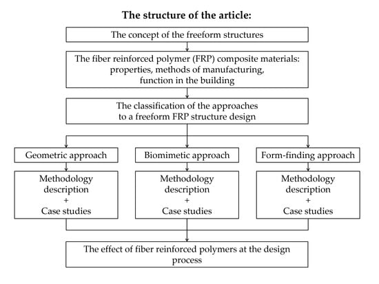
2. Freeform Structures Created by Using the Geometric Approach

2.1. What Is the Geometric Approach?

Freeform structures are usually created as mathematically described surfaces. Single and double curvature surfaces such as spheres, hyperbolic paraboloids, and other transfer and revolution surfaces are used to create freeform structures with this methodology. The great engineers Pier Luigi Nervi, Felix Candela, Eduardo Torroja, and Vladimir Shukhov created their masterpiece structures based on these principles. The development of computation design technologies has affected the fields of architecture and civil engineering and has allowed even the most irrational and sculptural shapes to be described mathematically.
The principles of creating freeform structures with the geometric approach lie in the field of differential geometry and surface theory. A broad description of analytical and differential geometry of regular analytical surfaces, with regard to its application in various fields of engineering and construction, can be found in [53]. One of the essential parameters during the design of freeform structures is the curvature behavior. The way to measure surface curvature is Gaussian curvature, which is a scalar product of two fundamental curvatures [54].
The development of computer-aided design tools and digital design and manufacturing led to the increasing complexity of the curved surfaces and structures in architecture. To deal with these complex shapes, Bézier curves and Bézier surfaces came from the field of automobile manufacturing. Now they are powerful architectural modeling tools. Bézier curves were independently developed by two French engineers: Pierre Bézier, who worked at Renault, and Paul de Casteljau at Citroën. NURBS, or Non-Uniform Rational B-Splines, which were the subsequent development of Bézier curves and surfaces, are the mathematical representations for describing and modeling curves and surfaces in computer-aided design and computer graphics [55,56]. They can accurately describe any shape of organic freeform 3D surface. They are now widely used in several fields of design, from computer mice to aircraft fuselages and ship hulls. NURBS geometry is applied in CAD software such as Autodesk Maya, Autodesk 3ds Max, SolidWorks, and Rhinoceros 3D. Rhinoceros 3D was created in 1998 and since then has become the most popular NURBS-based software among designers and architects [57].
With the development of digital design tools, it has become evident that freeform architecture creates a lot of geometric challenges, as well as many opportunities for optimization that require geometric understanding. Architectural geometry is a research discipline that has evolved in response to these challenges and solves the geometric issues of the fabrication of complex freeform architecture at an architectural scale. Smooth freeform surfaces usually require decomposition into flat panels and rationalization with polyhedral surfaces to be embodied into a real building. This is usually required for façade panels and gridshell structures. The way to approximate the smooth surface is to divide it into segments, which is called discretization. Discretization methods vary in the number of edges of the element, complexity of the joints, face curvature, material suitability, etc. [54]. For example, flat features are often preferred because manufacturing costs are generally lower than curved features. Surface triangulation is a common method of discretization. It is easy to represent a surface with a triangle mesh, but it is not usually the best solution for the subsequent construction process. This is because six edges meet in one node in a triangular mesh, which leads to complicated joints and a heavier structure [58]. Discretization with a quadrangular mesh has several advantages over the triangular mesh. It has fewer edges, which results in lower material usage, lower complexity of joints, and better structural transparency. The representation of a surface as a mesh of planar quadrilaterals is a much more complicated challenge. Architectural geometry solves these and similar tasks using methods of discrete differential geometry and global optimization.
So, the principles of the geometric approach help to define geometric laws according to which the structure will be generated, designed, and then manufactured.
The manufacturing technologies of FRP composites allow panels of double curvature to be created, instead of aiming for flat panels. The lightweight nature of composites also offers greater design freedom. Another benefit is that their properties allow FRP composites to be used for both façades and roof structures, as now most freeform façades and roofs flow smoothly into each other, forming a continuous envelope or “building skin”.

2.2. Geometrical Composite Freeform Structures: Case Studies

The composite materials in freeform structures can be a part of the building or the entire structure. The analysis of case studies helps to understand how designers work with this material and how they use it as a non-traditional solution in their tasks. Fiber-reinforced polymers have been used in civil engineering and architecture for a relatively long period of time, since the 1960s [59,60]. The market hall in Argenteuil, France, built in 1967, is one of the earliest complex geometry structures made of composite materials (Figure 3a). The 30 m diameter dome of the market hall consists of 30 pre-fabricated 6 mm thick GFRP shell elements on a supporting tubular steel construction [30].
Heinz Isler, an architect who is internationally renowned for his concrete shell structures, was also one of the first architects to experiment with composite materials in practice [61]. He appreciated the property of translucency of glass fiber-reinforced polymers, and initially used them as roof lights in his concrete shells in the 1950s, as the requirements for these shells were too large for Plexiglas [28]. The light domes were highly translucent sandwich structures with woven glass fabric skins and glass mat cores. Later, in 1956, Isler made a series of double-curved GFRP housings for pharmaceutical companies. The high insulating properties and the strength of the composites allowed light, thin self-supporting shell structures to be created. Another type of structure created by this great engineer was the “honeycomb” plate, made of GFRP square coffers. These coffers were connected together to form a flat corrugated plate, used as a translucent roof for structures such as gas stations [28]. These roofs are still in service today, which also shows the durability of composite materials.
The Clip-On project (Figure 3b), designed by Atelier van Lieshout with Klaar van der Lippe and completed in 1997, is a GFRP cantilevered room cell structure, attached from the outside to the surface of the façade of Utrecht’s Centraal Museum [30]. Clip-On is an experimental project, which combines all the following functions in one object—the envelope, insulating and load-bearing structure, and all the basic living functions. In this project, the lightness of the fiber-reinforced polymers helped bring an experimental idea to life and create a cantilevered structure of this size. The walls and the floor flow into each other to form the continuous sandwich envelope, composed of rigid polyurethane (hereinafter PUR) panels with GFRP facing layers on both sides. A steel strip was integrated into the perimeter of the envelope during production and fastened at each end to steel plates directly adjacent to the sandwich structure. The object is attached to the building at four points, which transfer the load to the wall [30].
The freeform composite roofs of the Yitzhak Rabin Center in Tel Aviv (Figure 3h), designed by Moshe Safdie Architects and opened in 2005, is an outstanding example of a GFRP large-span shell structure. The structural engineering was produced by Octatube Engineering and Solico Engineering, and the contractors for the GFRP roofs were Octatube International and Holland Composites. The design of the roof structures, described by M. Eekhout in [62,63], was an innovative process, in which architects collaborated with industrial, maritime, and aeronautical engineers. After a number of physical experiments on prototypes, budget calculations, and structural analysis, the final version of the roof was approved as a sandwich structure of foam with stressed GFRP skins on both sides. GFRP stringers were also added as structural ribs into the sandwich structure, which appeared to have too much flexibility. The manufacturing technique was taken from the techniques used to produce sailing ship hulls. Vacuum infusion with negative molds was chosen as the production technology. The roof shells were divided into more or less rectangular segments to facilitate the processes of production and logistics, and they were later connected at the construction site. This project demonstrates how an experimental mindset and close interdisciplinary collaboration leads to great results.
The Chanel Mobile Art Pavilion, designed by Zaha Hadid Architects and built in 2010, is a building with a fluid organic shape, obtained by using parametric modeling tools (Figure 3c). The pavilion was designed as a mobile structure, which would travel to thirteen different countries. The project had to meet the following requirements: low weight; resistance to wind, snow, and live loading; fire performance; compliance with the numerous regulations and standards of all the countries where it was going to be presented [64,65]. Moreover, the double-curved envelope demanded specific decisions to be made on the material. The steel framework of curved I-section ribs with double-curved GFRP panels was the solution to these challenges. The GFRP panels are 12 mm thick sandwich structures manufactured with hand lay-up technology.
The Heydar Aliyev Center in Baku, Azerbaijan, another project by Zaha Hadid Architects, completed in 2012, is an elaborate freeform structure, which organically unites the urban landscape with the building envelope (Figure 3d). The complex curvilinearity of the façade skin defined glass fiber-reinforced polymers (GFRP) and glass fiber-reinforced concrete (GFRC) as the most appropriate materials for the envelope structure [64,66]. As in the Chanel Mobile Art Pavilion, the composite panels were installed on a steel framework.
The Serpentine Pavilion (Figure 3e), created by BIG and opened in 2016, is a double-curved structure made of pultruded fiberglass bricks. The idea of the design was an “unzipped wall”, in which the straight line of the top of the wall splits into two curved sides to create the interior of the pavilion [67]. The structure consists of approximately two thousand fiberglass boxes, connected with cruciform aluminum extrusions. The properties of GFRP define the unusual appearance of the pavilion: the light passes through the bricks and ensures the permeability of the inner space and the environment. The Serpentine Pavilion is an example of how a freeform structure can be created without large amounts of unique, complex, and expensive elements being used.
The research pavilion of RWTH Aachen University (Figure 3f), constructed in 2015, consists of four hyperbolic paraboloid umbrella structures made of textile-reinforced concrete (TRC) on four steel-reinforced concrete columns. Each umbrella structure is 7 × 7 m square in plan. Use of a carbon fiber textile allowed the obtainment of a thickness of only 6 cm for shell structures. The concept of reinforcement was offered because of the flow of the principal stresses within the shell structure, as the textile reinforcement can only be activated in an optimal manner if the principal tensile direction coincides with the 0° orientation of the fibers in the fabric. Twelve layers of fabric were used in the shell structure. The research presented in [68] is limited to the issues of the structural design, construction, and fabrication of the pavilion, such as using TRC and textile reinforcement. The structural analysis of the pavilion, material behavior, and ultimate limit state assessment is described in [69].
Research presented by W. Hawkins et al., in [70] examines a new flooring system of textile-reinforced concrete shells with a foamed concrete fill, which can reduce the amount of materials in the building by half. The paper [70] describes the construction and testing of two TRC shell prototypes, each 18 mm thick, with a 2 m span, and 200 mm tall. Both shells were reinforced with two layers of AR glass fiber textile. One of the prototypes is filled with foamed concrete, and the second is unfilled. Both shells are a quarter-scale representation of a typical application in an office or residential building with 8 m spans between the columns. The reinforcement is an alkali-resistant glass fiber mesh with epoxy resin coating. A fine-grained concrete mix was developed to achieve good workability for the hand formation of 3 mm-thick layers, and a target compressive strength of approximately 32 GPa. The physical structural tests were carried out in several stages, including uniform loading, pre-stressing of the tie rods, and final asymmetric loading to determine the ultimate strength. In both cases, the design strength was exceeded. The ultimate capacity of the filled casing was 11.5% higher than that of the unfilled casing, and the rigidity also increased. The results of physical testing showed that both shells failed similarly, with the development of distinct regions of high curvature and cracking. The AR glass fiber textile reinforcement enabled large deformations to occur without sudden failure.
E. Sharei et al. [71] present research, experimental study, fabrication procedure, and physical tests on the TRC vault shell. The authors highlight the key issue of the application of TRC in the field of construction—the necessity of new modeling approaches to comprehend the structural behavior of these structures, and they also present an anisotropic strain-hardening material model specifically developed for the simulation of TRC shells. The comparison of the model with test results demonstrates the model’s ability to capture important aspects of the structural behavior of a structure, including the evolution of damage due to cracking and the load-bearing capacity of a structure.
E. Verwimp et al. [72] investigate buckling behavior under uniform pressure of a thin TRC dome structure with numerical and experimental tests. The numerical simulation was carried out using the Riks method in Abaqus and implementing geometrical imperfections. The dome had a base diameter of 2 m, a thickness of 3.7 mm, and a radius of curvature to thickness ratio of R/t = 722. To understand the structural behavior of the dome, it was observed during the experiment using strain gauges and digital image correlation. The physical testing was successful, and the results showed that the failure of the GFTR-IPC dome was the result of asymmetric buckling, which was the target, at the edge that was affected by the bending effect and imperfections. The simulations correspond well to the experimental data and validate the model, which enables the prediction of buckling, necessary when designing thin TRC shells.
Figure 3. Composite freeform structures, created with the geometric design approach: (a) Market Hall, Argenteuil, 1967, Paris, France [73], ©Pamela Voigt; (b) Project “Clip-On”, 1997, Utrecht, Netherlands [30], ©Valerie Spalding; (c) Chanel Mobile Art Pavilion, 2010, Paris, France [74], ©Stefan Tuchila; (d) Heydar Aliyev Center, 2013, Baku, Azerbaijan, ©Roman Bortsov; (e) Serpentine Gallery Pavilion, 2016, London, Great Britain [67], ©Laurian Ghinițoiu; (f) Research pavilion of RWTH Aachen University, 2015 [68]; (g) House of Dior Seoul, 2015, Seoul, South Korea [75], ©Kyungsub Shin; (h) Plastic Tower Sculpture, 2007, Stuttgart State Academy of Art and Design, Stuttgart, Germany [30], ©Valerie Spalding; (i) Freeform roofs of the Rabin Center, 2005, Tel Aviv, Israel, ©Octatube.
Buildings 11 00481 g003

3. Freeform Structures Created by Using the Biomimetic Approach

3.1. What Is Biomimetics?

Biomimetics is a large interdisciplinary field of science, which is based on the analysis of natural laws, systems, and mechanisms, and how they can be applied in different fields of science and technology. It integrates research disciplines such as biology, engineering, physics, architecture, chemistry, mathematics, and IT. The term “biomimetics” literally means “imitation of life” (from Ancient Greek “bios”—“life”, and “mīmēsis”—“imitation”). The earlier term “bionics” is a concept related to “biomimetics” and means “biologically inspired engineering”. The term “biomimetics” was established by Jack E. Steele in 1958 and used as an official term in a USAF Conference in 1960 [76].
Biomimetics deals with the analysis and understanding of natural processes and phenomena, and the creative implementation of the principles emphasized to solve challenges in other areas of science and technology, but it is not just a simple imitation of nature [77,78]. In the 1960s, the architect Frei Otto and biologist J.G. Helmcke drew parallels between technical and “natural” structures and discussed the similarities. Later, Frei Otto and his research group studied living and non-living structures within the framework of the research program “SFB 64—Weitgespannte Flächentragwerke”. The research was focused on the self-construction and self-organization of natural systems and the mechanisms of animal and human behavior in the context of housing and cities [79].
The biomimetic approach to design implies the dialog of the disciplines: functionally important features of biological systems are abstracted into models representing the properties of interest and underlying the design principles. This model serves for the functional implementation of morphology and provides technical implementation in biomimetic solutions [80]. One such feature is that in the natural system it is difficult (almost impossible) to separate the categories “material” and “structure”, and “structure” and “form”, which is a fundamental difference for architectural human-made systems [81]. Natural structures are multilayered, fine-tuned, and differentiated combinations of major components, which leads to structures that have multiple network functions. For example, the functionally important properties of a tree trunk (including mechanical properties such as stiffness, damping, and pre-stressing; transport of water and assimilated substances; accumulation of nutrients; adaptive growth; self-repair; thermal insulation, etc.) may vary in one hierarchical structural system [82].
J. Knippers and T. Speck [81] distinguish the following natural principles of architectural design: heterogeneity (natural structures are characterized by a geometric differentiation of their elements); anisotropy (commonly, natural structures consist of fiber-reinforced composite materials); hierarchy (biological systems are characterized by a multilevel hierarchical structure from nano- to macro-scale); multifunctionality (botany fibers simultaneously serve mechanical and diverse physiological functions).
L. Badarnah and U. Kadri [83] generalize existing investigations in biomimetic design and identify two strategies: (1) problem-based, which implies the search for a solution to a particular engineering problem in nature, and (2) solution-based, when the solution inspired by nature leads to development of new technology. The first strategy is known as top-down [84], challenge to biology [85], biomimetics by analogy [86], and problem-based [87]. The second strategy is defined by scientists by the following terms: biology-to-design [85], bottom-up [81,84], biomimetics by induction [86], and solution-based [87]. Bottom-up and top-down approaches, described by J. Knippers and T. Speck [81], can be found in Figure 4. The “bottom-up” or “biology push” approach implies that the first step is biological research. The “top-down” or “technology pull” approach is the opposite. The first step is the technical problem statement, and then the search for biological analogies and the identification of appropriate principles begins.
Developments in structural optimization show that biologically inspired methods have significantly higher potential to improve technical structures than a pure engineering approach [79]. Biomimetic research on FRP composites has been carried out by a large number of scientists [88,89,90,91,92]. The current review is limited to the analysis of biomimetic research and developments in freeform structure design. In this area, biomimetic developments take place in insulating, resisting, and envelope structures and also in the properties of materials. Biomimetic research in building skins includes energy waste control systems, kinematic systems, and adaptive architectural envelopes inspired by natural mechanisms [93,94].

3.2. Biomimetic Composite Freeform Structures: Case Studies

The FRP composites play a significant part in biomimetic research. One of the first architects who experimented with composite materials was R. Buckminster Fuller (1895–1983). He designed the bionic structure called the Fly’s Eye Dome (Figure 5a), which was based on his famous geodesic dome and aimed to combine a skin and a supporting structure, like an insect’s exoskeleton [73]. This dome structure was made of GFRP composite pre-cast module elements, and its shape was inspired by a variety of fly-eye lenses.
Pavilion COCOON_FS is a research pavilion, constructed of glass fiber-reinforced plastic modules (Figure 5b). Its organic shape was inspired by the geometric pore structure of marine diatoms [95]. The process of geometry optimization, segmentation, and preparation for fabrication is described in [96]. GFRP was used as a material for the construction because of its lightweight nature, high compressive and tensile strength, and the fact that it can be formed flexibly. Rhinoceros and Grasshopper software programs were used as digital form-finding and optimization tools. The pavilion was developed with self-supporting cell elements, which, at the same time, played the role of the envelope [97]. An optimization procedure was used to reduce the number of unique elements.
The research group of the Institute for Computational Design (ICD) and the Institute for Building Structures and Structural Design (ITKE) at the University of Stuttgart has made a great contribution to the research in the field of the biomimetic approach in freeform architecture. Several pavilions were developed with robotic coreless filament winding technology to transfer biomimetic principles into fiber-reinforced polymer laminate design.
The ICD/ITKE Research Pavilion 2012/2013 was a result of the biomimetic analysis of the structure and behavior of the cuticle of the American lobster (Figure 5c). S. Reichert et al. [98] presented a new integrative computational design methodology for design and fabrication of complex geometry structures with robotic filament winding technology. The methodology was demonstrated on the full-scale ultra-lightweight architectural pavilion of glass and fiber composites. The focus of the biomimetic research aspects is the analysis of the exoskeletons of arthropods with respect to their properties as natural lightweight fiber composites and their potential to provide information on the applications of FRP in architecture and design. Biological principles, such as anisotropy, heterogeneity, and multifunctionality, were integrated into this research using fabrication and structural principles to achieve a lightweight, performative material system on an architectural scale [99,100].
The ICD/ITKE Research Pavilion 2014/2015 (Figure 5d) is an adaptive, robotically manufactured fiber composite shell structure with pneumatic formwork. The shape of the pavilion was based on the biomimetic research of the diving bell water spider Argyroneta aquatica [101]. A description of the fabrication process of the pavilion is presented in [102].
The structure of the ICD/ITKE Research Pavilion 2016/2017 (Figure 5e) is a 12 m long cantilevering lattice composite shell, produced by the coreless filament winding method [103]. The aim of the research was to create a pavilion that exceeds the fabrication capabilities of one robotic arm, so the fabrication setup consisted of two KUKA robots and a drone. The structural design of the pavilion was carried out in two stages: in the first stage, the shape of the structure was considered a continuous shell with pseudo-isotropic material properties. In the second step, a detailed beam element model was used to define the correct layout and the amount of glass and carbon fiber reinforcement needed. The research project demonstrated the great potential of the innovative design and fabrication process proposed, and it also showed that the dimensional limitations of robotic fabrication can be expanded.
The BUGA pavilion was made to demonstrate the opportunities provided by robotic coreless filament winding to create lightweight lattice composite structures (Figure 5f). The span of the pavilion is 23 m, and the height is 6.8 m. Its structure is a gridshell made of bone-like load-bearing elements, covered by an ETFE membrane. The elements, which are made by using the coreless filament technique, are of prime interest to discuss. Each element was fabricated by a robotic arm in two stages, using different materials. Glass fibers were used in the first stage as a base lattice structure because of their lower cost, and, in the second stage, carbon fibers were added as reinforcement on the top of the glass fibers because of their higher strength and elastic modulus. The structural design, structural behavior, and geometrical optimization of the BUGA fiber pavilion are described by Gil Perez et al., in [104]. The pavilion was made according to biomimetic principles, as well as by following other research projects carried out by ICD and ITKE. The project uses principles borrowed from the natural world, from a morphological and a procedural point of view, to optimize the placement of materials in terms of quantity and location [105].
Adaptive or kinematic building structures and systems are extremely interesting in the field of biomimetic architectural and engineering research. Kinematic systems can respond to changing environmental conditions, for example temperature and solar radiation, and are widely used in façade systems. The biomimetic kinematic façade system, developed by Schleicher et al. [106,107] and Lienhard et al. [108], works by using the elastic deformation of the entire structure instead of local hinges. This system was inspired by the movement principle of the Strelitzia reginae or ‘bird of paradise’ flower. Strelitzia reginae has two adnate petals, which bend down and open their anthers and their style under the load of the bird. The bending leads to the opening of the petals. The functional-morphological analysis of the natural kinetic system and top-down biomimetic approach was used to create a kinematic façade shading system [109,110]. In this case, the use of fiber-reinforced polymers was crucial because these materials can combine high tensile strength with low flexural stiffness, thereby offering a wide range of calibrated elastic deformations.
Figure 5. Biomimetic composite structures: (a) Fly’s Eye Dome by B. Fuller, 1965, Miami, USA [73], ©Pamela Voigt; (b) Pavilion COCOON_FS, 2011, Jena, Germany, Pohl Architects [96], ©Jan-Ruben Fischer; (c) The ICD/ITKE Research Pavilion 2012/2013, Germany [111]; (d) ICD/ITKE Research Pavilion 2014/2015, Germany, 2015 [112]; (e) ICD/ITKE Research Pavilion 2016/2017, Germany [103]; (f) BUGA fiber pavilion, 2019, Germany [104]; (g) Flectofold prototype (kinematic façade system element), based on the Aldrovanda curved folding movement principle [113]; (h) Kinematic façade system for One Ocean Pavilion for EXPO 2012, based on the biomimetic principle of movement of the Strelitzia reginae [114], ©soma.
Buildings 11 00481 g005

4. Freeform Structures Created by Using the Form-Finding Approach

4.1. What Is Form-Finding?

The main idea of the form-finding approach is that physical and mechanical laws play a key part in the form generation process. K. Linkwitz [24] defines form-finding as searching for the equilibrium shape of a structure, which has to be adapted according to the forces acting within it. One of the examples of such shapes is soap film suspended within given boundary edges, which forms a very thin tension surface. In [23] the following definition of form-finding is given: “Form-finding is a forward process in which parameters are explicitly/directly controlled to find an ‘optimal’ geometry of a structure which is in static equilibrium with design loading.” In [115], Pottmann et al., define this approach as statics-aware design, highlighting its main idea—the insertion of statics analysis at the very first stage of conceptual design when the geometry of the structure is in the process of being defined. Bletzinger K. U. and Ramm E. in [116] describe form-finding as an iterative process of reducing the “design noise”, i.e., applying suitable filters to an infinite design space to obtain the shape of the structure that best suits the design objectives.
The simplest example of a shape in equilibrium, where form interacts with forces, is a freely hanging chain or catenary. This shape was one of the key ideas for further development of form-finding methods. It was formalized by Robert Hooke in 1676 into the law of the hanging chain: “As hangs the flexible line, so but inverted will stand the rigid arch”, although Hernández-Montes et al. [117] showed that hanging models were used by ancient builders in the design of Taq-i Kisra (540 AD). The form-finding methods can be classified as physical methods and numerical methods (Figure 6). For an extremely long period, only physical methods of form-finding were available. Two- and three-dimensional hanging models by Antoni Gaudí demonstrate the opportunities provided by physical modeling to create elegant equilibrium structures that follow the flow of the forces within them. Heinz Isler contributed greatly to experimental and physical form-finding and created a number of naturally form-found structures. His experiments with hanging models began when he saw wet burlap hanging on reinforcement mesh, and was inspired by its natural shape, hanging under its self-weight [118]. During his long creative process, he created more than a thousand shell structures, based on physical form-finding experiments instead of geometric concepts, with shapes defined by the laws of nature [119].
Extensive scientific work on the physical methods of the form-finding of freeform tension structures, membranes, and gridshells was carried out at the Institute of Lightweight Structures at the University of Stuttgart, founded by Frei Otto in 1964. The construction of the cable net structures of the Olympic stadium in Munich in 1972 became a full-scale implementation of this research work. To overcome the limitations of the physical methods of form-finding, Linkwitz and Shek developed the concept of force densities or force:length ratios [120]. This was the starting point for the force density method, a new numerical method of form-finding, which allowed a membrane structure to be presented as a general pin-joined network, and its equilibrium state to be described with a system of linear equations [121,122].
The result of the invention of the force density method and other numerical form-finding methods was overcoming the main disadvantage of physical modeling—a limited number of variants. With these tools, a lot of different equilibrium shapes can be defined at the conceptual design stage without time-consuming and expensive physical experiments.
The force density method was later modified and further developed by different researchers to give rise to a number of new form-finding methodologies, based on static equilibrium. Some of these are the geometric stiffness method [123], thrust network analysis [124,125], topological mapping for tension and compression structures [126,127,128], and the form-finding of compression structures with pre-stressing tendons [129]. Additionally, based on dynamic equilibrium, methods such as dynamic relaxation [130,131] and particle spring systems appeared [132]. A thorough review of existing analytical form-finding methods was made by D. Veenendaal and P. Block in [133].
Form-found or equilibrium structures can be classified, because of their equilibrium states, as compression structures, tension structures, or hybrid structures with both tension and compression elements (Figure 7). Tension structures are, for example, membranes and pre-stressed cable nets. Examples of compression-only structures are unreinforced domes and vaults [134]. Examples of hybrid structures are tensegrity structures, or compression structures with pre-stressing tendons [129].
The main principle of all the form-finding methods can be formulated as “the form follows the forces acting in it”. Therefore, the objective of the form-finding approach is to unite the static analysis of load bearing behavior and finding of the aesthetically expressive shape of the structure.

4.2. Form-Found Composite Freeform Structures: Case Studies

An elastic gridshell is a structure whose shape is obtained by using form-finding methods. This type of structure was invented by Frei Otto during his form-finding experiments. The construction process of these structures is highly specific. A gridshell is a structure that acts as a shell, i.e., resists the loads through the membrane action because of its curvature, but it is made of a grid instead of a solid surface. An elastic gridshell is a double-curved freeform structure, whose final shape is obtained by raising the initially flat grid of elastic elements and then fixing it into the curved spatial shape.
As the form of an elastic gridshell results from a post-buckling state of the tubes, it is difficult to predict its equilibrium shape, and traditional form-finding methods are not suitable for these purposes. C. Douthe et al. [135] present an adaptation of the dynamic relaxation algorithm for structures that have been pre-stressed by bending, and develop a numerical tool implemented in Scilab. The researchers also provide the validation of the algorithm by comparison with the finite element software, and its application to the form-finding of a gridshell. The analysis of the model indicates that the structural stresses remain quite reasonable, so this type of structure can be efficient for the construction of temporary or permanent buildings. C. Douthe et al. [136] highlight the limitations of the traditional approach to construction with composites, when structures made of new materials blindly copy existing structural types, while their specific properties require specific structural forms and construction methods. Investigations into the short- and long-term behavior of GFRP composites under permanent bending, presented in [136], show that they are attractive materials for gridshells. To confirm these investigations, a prototype of an elastic gridshell, form-found by using the dynamic relaxation method, was built and loaded (Figure 8d). The prototype is 3.7 m high, 22 m long, and 8 m wide. The approximate area covered by it is about 160 m2. The gridshell consists of GFRP pultruded tubes. Results of physical and numerical experiments demonstrate the high potential for application of composite materials in elastic gridshell structures [137]. In [138], a new, more general form-finding model is developed, where the twisting of the beams in the structure is taken into account.
F. Tayeb et al. [139] consider the buckling of a 300m2 composite gridshell prototype for Solidays festival (Figure 8e). Buckling has to be avoided in such structures because it causes high stresses in the beams and may lead to the sudden collapse of the structure. The analysis of the prototype under Ultimate Limit State has to be far from buckling. The accident simulation is modeled in the research: several elements are broken from the ULS in order to understand the behavior of the structure in the event of an accident. The pseudo-plasticity of the designed structure is demonstrated because of the redundancy of the structural concept of the gridshell. The problem of buckling of elastic gridshells is thoroughly discussed by B. Lefevre et al., in [140].
The hybrid structural skin is a prototype of a GFRP elastic gridshell braced by a fiber-reinforced concrete envelope (Figure 8g), which was built at the École des Ponts ParisTech in 2017. This project investigates the feasibility of a new kind of shell, which combines an elastic gridshell with a bracing fiber-reinforced concrete envelope to create a rigid lightweight roof system with no additional scaffolding and limitless forms [141]. The shape of this structure was found by using the dynamic relaxation method. The aim of the research project was to overcome the limitations of two types of structures: the difficulties in the bracing and covering of elastic gridshells and the expensive formwork for concrete shell structures. The grid of GFRP rods plays the part of a lightweight elastic permanent formwork in the shell structure. The prototype consists of the following layers: GFRP gridshell, fiberglass mesh formwork, and a 15 mm thick concrete envelope, making up a hybrid composite structure. Research work in [141] shows the high potential of the novel type of shell structure for larger scale applications.
Figure 8. (a) The soap model prototype structure of the German Pavilion, Montreal, 1967 [142], ©Institute for Lightweight Structures and Conceptual Design; (b,c) Photos of experiments by Heintz Isler [23], ©Frank Döring; (d) The prototype of a composite gridshell at the UR Navier laboratory and the École Nationale des Science Géographique, 2010 [136], ©Cyril Douthe; (e) Solidays festival gridshell prototype at the UR Navier laboratory, 2011 [139]; (f) Bending-Activated Tensegrity structure, 2015 [143]; (g) 3 × 3 m prototype of a GFRP gridshell braced by a concrete envelope built at the École des Ponts ParisTech [141], ©Cyril Douthe; (h) The elastic gridshell at the Ephemeral Cathedral, 2013 [144]; (i) The full-scale prototype of the roof of the NEST HiLo unit, 2017 [145].
Buildings 11 00481 g008
The roof of the Ephemeral Cathedral of Créteil (Figure 8h), built in Paris in 2013, is a large-span elastic GFRP gridshell, which demonstrates the advantages of the application of composites in full-scale complex architecture projects [144]. It was designed as a temporary church building during the two-year renovation of the permanent cathedral. The edifice covers an area of 350 m2 and can accommodate up to 500 people. Its double-curved organic shape was obtained by using the dynamic relaxation algorithm [146]. The gridshell structure was constructed of pultruded GFRP tubes with a diameter of 42 mm, connected together with scaffold swivel couplers. An innovative installation process was developed, taking advantage of the flexibility of thin GFRP elements. Initially, a regular flat grid of tubes was built on the ground. The elements were fastened together in such a way that the mesh had no shear stiffness in plane and could withstand large-scale deformations during installation. Then the mesh was elastically bent to its definitive shape, and finally, was fixed in the desired shape with a third layer of stiffening tube elements.
The Bending-Activated Tensegrity structure (Figure 8f) is a modular 6 × 6 m installation that was made by the team of Chair of Structural Design in the Technische Universität München for the 2015 IASS Symposium Contest. The combination of the benefits of active bending with a tensegrity and membrane system resulted in a brand new structural type. Elastically bent GFRP rods were used in combination with PVC membranes and polyester belts to form a pre-stressed and self-stabilizing structure [143,147]. The form of the structure was determined through FEM simulation, as a result of the relation of stresses between rods, membranes, and belts.
The full-scale prototype of the roof of the NEST HiLo unit (Figure 8i) is an experimental research project carried out at the Robotic Fabrication Lab at the Institute of Technology in Architecture at ETH Zürich in 2017. The project was carried out to demonstrate the opportunities of a new formwork and reinforcement system for thin concrete shell structures [145,148]. The aim of the research was to develop a new cost-effective and efficient way to build structures with complex double-curved geometries. Carbon fiber reinforcement was used in the project as it is the most suitable material for this type of structure. Carbon fiber mats as 1.2 × 5 m flat panels were patterned and cut to adapt to the shape of the double-curved roof.
The ICD/ITKE research group of the University of Stuttgart presented investigations in the field of production of load-bearing components for slabs with coreless filament winding (CFW) technology [149]. The research develops a new approach to design and fabrication of filigree shell structures, and an optimization module with stress and associated manufacturing data. The results of the study were evaluated by fabricating and testing a prototype of the supporting slab weighing 10.2 kg. The structure withstood a load of 559 kg with a span of 2.7 m, which demonstrated the effectiveness of the approach. The range of analyzed FRP freeform structures in chronological order from the beginning of the application of composite materials to the present day is presented in Table 2.

5. Future Trends

The review of built objects has shown many factors that constrain the use of composites in architecture. These factors can help to define the direction that further research should take. One such issue is the improvement of the properties of composite materials, such as insulation and fire resistance properties, to widen their use in building construction. Another research direction is the development of new types of composite structures, for example kinetic gridshell structures [161,162], structures with shape-memory polymers [163,164,165], and tensegrity composite structures.
A. E. Naaman [166] highlights possible future research questions in thin TRC structures, such as 3D textiles with built-in curvature in one or two directions; 2D or 3D textiles with hybrid reinforcement, such as carbon and PP; and development of highly drapable 2D and 3D textiles for use in curved shell structures. One high-potential research field is the exploration of self-stressing composites using fibers or textiles with useful deformation recovery properties, which can be achieved by a possible combination of controlled matrix expansion and fiber or textile deformation recovery.
Another potential area of future research is the development of new specific design and manufacturing methods for structures with advanced composite materials, as well as development of existing ones. L. Vasey et al. [101] highlight the synthesis and synergy of design and production processes as an inevitable future trend. The development of factory-based design methods, for example, the multistage filament winding method [167] and the shape optimization-to-fabrication method [149,168], is relevant for composite structures.
The environmental impact of building structures is one of the most important issues in civil and industrial engineering, and also an important direction of ongoing research and innovative developments. The factory-based production of FRP materials, with high thermal insulating properties, high durability, and minimal repair costs, makes composites a competitive material in this area [169]. Comparison of the costs of different materials for bridge construction shows that combining initial costs and maintenance costs makes steel the cheapest material, followed by FRP, aluminum, and then stainless steel. The analysis of embodied energy demonstrates that FRP uses less than half the energy of other materials, and when assessing the impacts of pollution, FRP is a winner [169]. Although the construction and maintenance of FRP show good results, the end of life, utilization, and recycling process of FRP materials are critical issues that demand further investigations. A detailed review of the recycling of composite materials is presented in [170].

6. Conclusions

This article provides a survey analyzing freeform structures from the shape generation and conceptual design point of view. An attempt to analyze and classify the diversity of freeform structures was made in the paper. The role of FRP composites in freeform structure design is also discussed. Both a scientific literature review and a historical review of constructed objects are presented. A new classification of freeform composite structures is developed. Freeform structures are classified according to the methodology applied at the conceptual design stage: the geometric approach, the biomimetic approach, and the form-finding approach.
After the analysis of the three approaches, we can highlight the following main problems or challenges that each approach aims to solve. In the geometric approach, in most of the cases, the purpose is to create an artistically expressive structure by the means available to architects and engineers. These means are knowledge about the geometric laws of shape generation or tools created on the basis of this knowledge (for example, tools of the Rhinoceros software, created on the basis of NURBS). The main aim of the geometric approach is to define any complex double-curved shape (even the most sculptural) as a mathematically described surface, or some discretized mesh. In the biomimetic approach, the main challenge is to create a structure that mimics some natural system and imitates some natural mechanisms or behavior. In the form-finding approach, the aim is to create a structure whose shape follows the forces acting in it. The strength of this method is that the static analysis is part of the shape-finding process. So, comparing the three approaches, we can conclude that the main weakness of the geometric approach is that the issues of static equilibrium, stability, and structural behavior are commonly not taken into account during the shape generation process. This may lead to ineffective structures with consequences such as large bending moments, excessive consumption of materials, and, as a result, high construction costs. Structures created by the biomimetic approach are more competitive in this sense, because in this case designers are deeply studying, analyzing, and adopting natural structures and systems. Biological structures appeared much earlier than artificial ones and are much more effectively designed to perform the functions for which they were conceived. Nature has the tools of thousands of years of evolution, and it is still a better engineer than a human can be. The form-finding approach, in a sense, is based on the physical-mathematical principles of the bionic approach, as the first structures were created after observations of nature and natural laws (stretched web, soap skin, hanging ropes). Therefore, the advantage of form-found structures is that they are more well-conceived ones with a more rational use of material, and consequently a decrease in cost, which is especially valuable for complex geometry buildings. The important issue in this case is that the shape of form-found structures is designed for some special equilibrium state, most commonly under the dead load. So, further structural analysis is necessary to fully understand the performance of the structure (e.g., analysis of live or dynamic loads).
The analysis of case studies shows that the properties of composite materials significantly affect the design and form generation processes in all of the three methodologies. The application of FRP composites in structures created by the geometric approach helps to overcome the above-described limitation of this method due to the extremely light own weight and high stiffness to weight ratio of these materials. Thus, the bending moments from the dead loads can be significantly reduced. In the case of the biomimetic approach, composite materials play a significant part due to their anisotropy structure, which is most commonly found in biological systems. Another important property that justifies the use of FRP materials in biomimetic structures is the combination of different functions in one material, as well as a smooth change in the properties of the material along its thickness, again due to anisotropy. For example, composites can provide a load-bearing structure and at the same time integrate protective functions of the envelope, because of their chemical and corrosion resistance and excellent insulation properties. The application of FRP composites in form-found structures, for example, elastic gridshells or Bending-Activated Tensegrity structure, demonstrates that the material can directly define the form-finding and design methods. The elastic properties of composites here are the key factors of design. On the other hand, it has to be noted that these properties add challenges to the design process. For example, anisotropy of composite materials requires more sophisticated methods of structural analysis, as well as specific methods of manufacturing. This review demonstrates the high potential for the use of advanced composite materials to create efficient and performative structures, especially in freeform, complex, and non-standard cases.

Author Contributions

Conceptualization, A.S., E.H.-M., and A.M.; methodology, A.S., E.H.-M., and A.M.; writing—original draft preparation, A.M., E.H.-M., and A.S.; writing—review and editing, A.M., E.H.-M., and A.S.; visualization, A.M.; supervision, A.S.; project administration, A.S. All authors have read and agreed to the published version of the manuscript.

Funding

This research did not receive any specific grant from funding agencies in the public, commercial, or not-for-profit sectors.

Conflicts of Interest

The authors declare no conflict of interest.

References

  1. Veltkamp, M. Free Form Structural Design: Schemes, Systems & Prototypes of Structures for Irregular Shaped Buildings; IOS Press BV: Amsterdam, The Netherlands, 2007. [Google Scholar]
  2. Kim, K.; Son, K.; Kim, E.D.; Kim, S. Current trends and future directions of free-form building technology. Archit. Sci. Rev. 2015, 58, 230–243. [Google Scholar] [CrossRef]
  3. Eekhout, M.; Gelder, B. Case Study E Management of Complex Free Form Design and Engineering Processes. In Architectural Management: International Research and Practice; Wiley-Blackwell: Singapore, 2009; pp. 244–267. ISBN 9781405177863. [Google Scholar]
  4. Li, Q. Form Follows Force: A theoretical framework for Structural Morphology, and Form-Finding research on shell structures. A+BE Archit. Built Environ. 2018, 8, 1–278. [Google Scholar] [CrossRef]
  5. Kim, S.; Son, S.; Lee, D. Development of Sustainable Production Technology of Free-Form Concrete Panels Using a Multi-Point Press CNC Machine. Sustainability 2021, 13, 1990. [Google Scholar] [CrossRef]
  6. Waimer, F.; Noack, T.; Schmid, A.; Bechmann, R. The Railway Station Stuttgart 21—Computational Design and Digital Fabrication of Freeform Concrete Shells, Proceedings of IASS Annual Symposia, IASS 2019 Barcelona Symposium: Realizations, Case Studies, Barcelona, Spain, 7–9 October 2019; International Association for Shell and Spatial Structures (IASS): Barcelona, Spain, 2019; pp. 1–8. [Google Scholar]
  7. Poirriez, C.; Franceschi, M.; Bouzida, Y. Parametrization, integration and buildability: Design and construction of a 50M span freeform roof in Bangkok. J. Int. Assoc. Shell Spat. Struct. 2019, 60, 287–293. [Google Scholar] [CrossRef]
  8. Schleicher, S.; Herrmann, M. Constructing hybrid gridshells using bending-active formwork. Int. J. Sp. Struct. 2020, 35, 80–89. [Google Scholar] [CrossRef]
  9. San, B.; Feng, D.; Qiu, Y. Shape optimization of concrete free-form shells considering material damage. Eng. Optim. 2021, 53, 1–18. [Google Scholar] [CrossRef]
  10. Abramczyk, J. Symmetric Free Form Building Structures Arranged Regularly on Smooth Surfaces with Polyhedral Nets. Symmetry 2020, 12, 763. [Google Scholar] [CrossRef]
  11. Kavuma, A.; Ock, J.; Jang, H. Factors influencing Time and Cost Overruns on Freeform Construction Projects. KSCE J. Civ. Eng. 2019, 23, 1442–1450. [Google Scholar] [CrossRef]
  12. Wang, X.; Zhu, S.; Zeng, Q.; Guo, X. Improved multi-objective Hybrid Genetic Algorithm for Shape and Size Optimization of Free-form latticed structures. J. Build. Eng. 2021, 43, 102902. [Google Scholar] [CrossRef]
  13. Wang, Z.; Cao, Z.; Fan, F.; Sun, Y. Shape optimization of free-form grid structures based on the sensitivity hybrid multi-objective evolutionary algorithm. J. Build. Eng. 2021, 44, 102538. [Google Scholar] [CrossRef]
  14. Tellier, X.; Douthe, C.; Hauswirth, L.; Baverel, O. Fabrication-Aware Design of Architectural Envelopes Using Surfaces with Planar Curvature Lines, Proceedings of IASS Annual Symposia, IASS 2019 Barcelona Symposium: Realizations, Case Studies, Barcelona, Spain, 7–9 October 2019; International Association for Shell and Spatial Structures (IASS): Barcelona, Spain, 2019. [Google Scholar]
  15. Wakasa, M.; Shimoda, M. Free-form optimization for controlling time-dependent responses of shell structures. Struct. Multidiscip. Optim. 2019, 60, 1545–1560. [Google Scholar] [CrossRef]
  16. Hameed, A.; Al Alwan, H.; Oukaili, N. Architectural Potentiality of Free-Form Structures, Proceedings of the 3rd European and Mediterranean Structural Engineering and Construction Conference 2020, Limassol, Cyprus, 3–8 August 2020; ISEC Press: Fargo, ND, USA, 2020. [Google Scholar]
  17. Eekhout, M. Form as a Bridge between Architectural, Structural and Industrial Design. In Proceedings of the 4th International colloqium on Structural Morphology IASS: Spatial Lattice and Tension Structures, Delft, The Netherlands, 17–19 August 2000; pp. 1000–1010. [Google Scholar]
  18. Wester, T. Nature of Structural Morphology and Some Interdisciplinary Examples, Proceedings of the IASS-ASCE International Symposium 1994 on Spatial, Lattice and Tension Structures, Atlanta, GA, USA, 24–28 April 1994; ASCE: Reston, VA, USA, 1994; pp. 1000–1009. [Google Scholar]
  19. Li, Q.; Borgart, A.; Wu, Y. How to understand “structural morphology”? J. Int. Assoc. Shell Spat. Struct. 2016, 57, 145–158. [Google Scholar] [CrossRef]
  20. Abramczyk, J. Transformed Corrugated Shell Units Used as a Material Determining Unconventional Forms of Complex Building Structures. Materials 2021, 14, 2402. [Google Scholar] [CrossRef] [PubMed]
  21. Pantazis, E.; Gerber, D.J. Beyond geometric complexity: A critical review of complexity theory and how it relates to architecture engineering and construction. Archit. Sci. Rev. 2019, 62, 371–388. [Google Scholar] [CrossRef]
  22. Gero, J.S. Computational Models of Innovative and Creative Design Processes. Technol. Forecast. Soc. Change 2000, 64, 183–196. [Google Scholar] [CrossRef]
  23. Williams, C. What is a shell? In Shell Structures for Architecture: Form Finding and Optimization; Routledge: New York, NY, USA, 2014; pp. 21–31. [Google Scholar]
  24. Linkwitz, K. About formfinding of double-curved structures. Eng. Struct. 1999, 21, 709–718. [Google Scholar] [CrossRef]
  25. Abramczyk, J. Folded Sheets as a Universal Material for Shaping Transformed Shell Roofs. Materials 2021, 14, 2051. [Google Scholar] [CrossRef] [PubMed]
  26. Abramczyk, J. Transformed Shell Structures Determined by Regular Networks as a Complex Material for Roofing. Materials 2021, 14, 3582. [Google Scholar] [CrossRef]
  27. Minchenkov, K.; Vedernikov, A.; Safonov, A.; Akhatov, I. Thermoplastic pultrusion: A review. Polymers 2021, 13, 180. [Google Scholar] [CrossRef]
  28. Knippers, J.; Cremers, J.; Gabler, M.; Lienhard, J. Construction Manual for Polymers + Membranes; Walter de Gruyter: Berlin, Germany, 2012. [Google Scholar]
  29. Vedernikov, A.; Nasonov, Y.; Korotkov, R.; Gusev, S.; Akhatov, I.; Safonov, A. Effects of additives on the cure kinetics of vinyl ester pultrusion resins. J. Compos. Mater. 2021, 00219983211001528. [Google Scholar] [CrossRef]
  30. Engelsmann, S.; Spalding, V.; Peters, S. Plastics in Architecture and Construction; Walter de Gruyter: Berlin, Germany, 2012. [Google Scholar]
  31. Vedernikov, A.; Tucci, F.; Carlone, P.; Gusev, S.; Konev, S.; Firsov, D.; Akhatov, I.; Safonov, A. Effects of pulling speed on structural performance of L-shaped pultruded profiles. Compos. Struct. 2021, 255, 112967. [Google Scholar] [CrossRef]
  32. Safonov, A.; Gusev, M.; Saratov, A.; Konstantinov, A.; Sergeichev, I.; Konev, S.; Gusev, S.; Akhatov, I. Modeling of cracking during pultrusion of large-size profiles. Compos. Struct. 2020, 235, 111801. [Google Scholar] [CrossRef]
  33. Vedernikov, A.; Safonov, A.; Tucci, F.; Carlone, P.; Akhatov, I. Modeling spring-in of l-shaped structural profiles pultruded at different pulling speeds. Polymers 2021, 13, 2748. [Google Scholar] [CrossRef]
  34. Alajarmeh, O.; Zeng, X.; Aravinthan, T.; Shelley, T.; Alhawamdeh, M.; Mohammed, A.; Nicol, L.; Vedernikov, A.; Safonov, A.; Schubel, P. Compressive behaviour of hollow box pultruded FRP columns with continuous-wound fibres. Thin-Walled Struct. 2021, 168, 108300. [Google Scholar] [CrossRef]
  35. Vedernikov, A.; Safonov, A.; Tucci, F.; Carlone, P.; Akhatov, I. Pultruded materials and structures: A review. J. Compos. Mater. 2020, 54, 4081–4117. [Google Scholar] [CrossRef]
  36. Tinkov, D.V.; Safonov, A.A. Design optimization of truss bridge structures of composite materials. J. Mach. Manuf. Reliab. 2017, 46, 46–52. [Google Scholar] [CrossRef]
  37. Sorina, T.G.; Safonov, A.A.; Khairetdinov, A.K. Pecularities of using carbon glass-reinforced plastic in pultrusion composite profiles for bridge engineering. J. Mach. Manuf. Reliab. 2010, 39, 47–51. [Google Scholar] [CrossRef]
  38. Bakis, C.E.; Bank, L.C.; Asce, F.; Brown, V.L.; Asce, M.; Cosenza, E.; Davalos, J.F.; Asce, A.M.; Lesko, J.J.; Machida, A.; et al. Fibre Reinforced Polymer Composites for Construction—State-of-the-Art Review. J. Compos. Constr. 2002, 6, 73–87. [Google Scholar] [CrossRef] [Green Version]
  39. Starr, T.F. Pultrusion for Engineers; Woodhead Publishing: Sawston, UK, 2000; ISBN 9781855734258. [Google Scholar]
  40. Bank, L.C. Composites for Construction: Structural Design with FRP Materials; John Wiley and Sons: Hoboken, NJ, USA, 2007; ISBN 0471681261. [Google Scholar]
  41. Raupach, M.; Morales Cruz, C. Textile-Reinforced Concrete: Selected Case Studies. In Textile Fibre Composites in Civil Engineering; Elsevier Inc.: Amsterdam, The Netherlands, 2016; pp. 275–299. ISBN 9781782424697. [Google Scholar]
  42. Ehlig, D.; Schladitz, F.; Frenzel, M.; Curbach, M. Textilbeton—Ausgeführte Projekte im Überblick. Beton Stahlbetonbau 2012, 107, 777–785. [Google Scholar] [CrossRef]
  43. Tysmans, T.; Adriaenssens, S.; Wastiels, J. Form finding methodology for force-modelled anticlastic shells in glass fibre textile reinforced cement composites. Eng. Struct. 2011, 33, 2603–2611. [Google Scholar] [CrossRef]
  44. Solico. Benefits of Composite Materials. Available online: https://www.solico.nl/about-us/benefits-of-composite-materials (accessed on 25 January 2021).
  45. Bedon, C. Review on the use of FRP composites for façades and building skins. Am. J. Eng. Appl. Sci. 2016, 9, 713–723. [Google Scholar] [CrossRef] [Green Version]
  46. Gates, P.; Ibell, T.; Darby, A.; Evernden, M.; Kragh, M. Advanced composites for façade retrofit. Struct. Eng. 2012, 90, 46–48. [Google Scholar]
  47. Bedon, C.; Agullo, C.P.; Luna-Navarro, A.; Overend, M.; Favoino, F. Thermo-Mechanical Investigation of Novel GFRP-Glass Sandwich Facade Components, Proceedings of the Challenging Glass 6: Conference on Architectural and Structural Applications of Glass, CGC 2018—Proceedings, Delft, The Netherlands, 17–18 May 2018; TU Delft Open: Delft, The Netherlands, 2018; pp. 501–512. [Google Scholar]
  48. Nguyen, K.T.Q.; Navaratnam, S.; Mendis, P.; Zhang, K.; Barnett, J.; Wang, H. Fire safety of composites in prefabricated buildings: From fibre reinforced polymer to textile reinforced concrete. Compos. Part B Eng. 2020, 187, 107815. [Google Scholar] [CrossRef]
  49. Henriksen, T.; Lo, S.; Knaack, U. The impact of a new mould system as part of a novel manufacturing process for complex geometry thin-walled GFRC. Archit. Eng. Des. Manag. 2016, 12, 231–249. [Google Scholar] [CrossRef] [Green Version]
  50. Schipper, R.; Eigenraam, P.; Grünewald, S.; Soru, M.; Nap, P.; Overveld, B.V.A.N.; Vermeulen, J. Kine-Mould: Manufacturing Technology for Curved Architectural Elements in Concrete, Proceedings of the IASS Annual Symposia, IASS 2015 Amsterdam Symposium: Future Visions—Symposium on Flexible Formwork, Amsterdam, The Netherlands, 16–20 August; International Association for Shell and Spatial Structures: Amsterdam, The Netherlands, 2015. [Google Scholar]
  51. Adapa. Adaptive Mould D300—Adaptive Moulds. Available online: https://adapa.dk/portfolio-item/adaptive-mould-d300-2/ (accessed on 23 March 2021).
  52. Henriksen, T.; Lo, S.; Knaack, U. A new method to advance complex geometry thin-walled glass fibre reinforced concrete elements. J. Build. Eng. 2016, 6, 243–251. [Google Scholar] [CrossRef] [Green Version]
  53. Krivoshapko, S.N.; Ivanov, V.N. Encyclopedia of Analytical Surfaces; Springer: Cham, Switzerland, 2015. [Google Scholar]
  54. Henriksson, V.; Hult, M. Rationalizing Freeform Architecture—Surface Discretization and Multi-Objective Optimization. Master’s Thesis, Chalmers University of Technology, Göteborg, Sweden, 2015. [Google Scholar]
  55. Rogers, D.F. An Introduction to NURBS: With Historical Perspective; Morgan Kaufmann Publishers: Burlington, NJ, USA, 2001. [Google Scholar]
  56. Farin, G. From Conics to NURBS: A Tutorial and Survey. IEEE Comput. Graph. Appl. 1992, 12, 78–86. [Google Scholar] [CrossRef]
  57. Caetano, I.; Leitão, A. Architecture meets computation: An overview of the evolution of computational design approaches in architecture. Archit. Sci. Rev. 2020, 63, 165–174. [Google Scholar] [CrossRef]
  58. Pottmann, H.; Wallner, J. Freeform architecture and discrete differential geometry. In Discrete Geometry for Computer Imagery—DGCI 2017; Lecture Notes in Computer Science (Including Subseries Lecture Notes in Artificial Intelligence and Lecture Notes in Bioinformatics); Springer: Berlin/Heidelberg, Germany, 2017; Volume 10502, pp. 3–8. [Google Scholar]
  59. Genzel, E. Zur Geschichte der Konstruktion und der Bemessung von Tragwerken des Hochbaus aus faserverstärkten Kunststoffen 1950–1980. Ph.D. Thesis, Bauhaus-Universität Weimar, Weimar, Germany, 2006. [Google Scholar]
  60. Hollaway, L.C. The evolution of and the way forward for advanced polymer composites in the civil infrastructure. In Proceedings of the Construction and Building Materials; Elsevier: Amsterdam, The Netherlands, 2003; Volume 17, pp. 365–378. [Google Scholar]
  61. Harries, K.A.; Chen, J.-F.; Presidents, V.; Bakis, C.E.; Kotynia, R.; Wu, Z.-S.; Smith, S.T.; Bisby, L.A.; Dai, J.-G.; El-Hacha, R.; et al. FRP International; International Institute for FRP in Construction: Kingston, ON, Canada, 2011; Volume 8. [Google Scholar]
  62. Eekhout, M. Composite stressed skin roofs for liquid design architecture. Int. J. Struct. Eng. 2010, 1, 255–279. [Google Scholar] [CrossRef]
  63. Eekhout, A.J.C.M.; Wichers, S. Lord of the Wings: The Making of Free Form Architecture; IOS Press—Delft University Press: Amsterdam, The Netherlands, 2016. [Google Scholar]
  64. Zaha Hadid Architects. Mobile Art Chanel Contemporary Art Container. Available online: https://www.zaha-hadid.com/architecture/chanel-art-pavilion/ (accessed on 7 December 2020).
  65. Pazdur-Czarnowska, A. Ecological Properties of Glass Fibre Reinforced Materials Based on Architecture of Zaha Hadid. In Proceedings of the IOP Conference Series: Materials Science and Engineering; IOP Publishing: Bristol, UK, 2019; Volume 471. [Google Scholar]
  66. ArchDaily. Heydar Aliyev Center/Zaha Hadid Architects. Available online: https://www.archdaily.com/448774/heydar-aliyev-center-zaha-hadid-architects?ad_medium=gallery (accessed on 7 December 2020).
  67. ArchDaily. BIG’s 2016 Serpentine Pavilion Opens Alongside 4 Summerhouses. Available online: https://www.archdaily.com/789018/bigs-2016-serpentine-pavilion-opens-alongside-4-summerhouses (accessed on 7 December 2020).
  68. Scholzen, A.; Chudoba, R.; Hegger, J. Thin-walled shell structures made of textile-reinforced concrete: Part I: Structural design and construction. Struct. Concr. 2015, 16, 106–114. [Google Scholar] [CrossRef]
  69. Scholzen, A.; Chudoba, R.; Hegger, J. Thin-walled shell structures made of textile-reinforced concrete: Part II: Experimental characterization, ultimate limit state assessment and numerical simulation. Struct. Concr. 2015, 16, 115–124. [Google Scholar] [CrossRef]
  70. Hawkins, W.; Orr, J.; Shepherd, P.; Ibell, T. Design, Construction and Testing of a Low Carbon Thin-Shell Concrete Flooring System. Structures 2019, 18, 60–71. [Google Scholar] [CrossRef]
  71. Sharei, E.; Scholzen, A.; Hegger, J.; Chudoba, R. Structural behavior of a lightweight, textile-reinforced concrete barrel vault shell. Compos. Struct. 2017, 171, 505–514. [Google Scholar] [CrossRef]
  72. Verwimp, E.; Tysmans, T.; Mollaert, M.; Berg, S. Experimental and numerical buckling analysis of a thin TRC dome. Thin-Walled Struct. 2015, 94, 89–97. [Google Scholar] [CrossRef]
  73. Voigt, P. Die Pionierphase des Bauens mit Glasfaserverstärkten Kunststoffen (GFK) 1942 bis 1980. Ph.D. Thesis, Bauhaus-Universität Weimar, Weimar, Germany, 2007. [Google Scholar]
  74. ArchDaily. Chanel Mobile Art Pavilion/Zaha Hadid Architects. Available online: https://www.archdaily.com/144378/chanel-mobile-art-pavilion-zaha-hadid-architects (accessed on 11 March 2021).
  75. New Christian Dior Flagship Store in Seoul Reflects Dior’s Soft And Flowing Style. Available online: https://worldarchitecture.org/articles/ccmpc/new-christian-dior-flagship-store-in-seoul-reflects-diors-soft-and-flowing-style.html (accessed on 14 July 2021).
  76. McCulloch, W.S.; Kelly, P.M. Living Prototypes—The Key to New Technology, Proceedings of the Bionics-Symposium, Dayton, OH, USA, 13–15 September 1961; Directorate of Advanced Systems Technology, Wright Air Development Division, Air Research and Development Command, U.S. Air Force: Dayton, OH, USA, 1961.
  77. Pohl, G.; Nachtigall, W. Biomimetics for Architecture & Design; Springer: Cham, Switzerland, 2015. [Google Scholar]
  78. Torgal, F.P.; Labrincha, J.A.; Diamanti, M.V.; Yu, C.P.; Lee, H.K. Biotechnologies and Biomimetics for Civil Engineering; Springer: Cham, Switzerland, 2015. [Google Scholar]
  79. Pohl, G.; Speck, T.; Speck, O.; Pohl, J. The role of textiles in providing biomimetic solutions for construction. In Textiles, Polymers and Composites for Buildings; Elsevier: Amsterdam, The Netherlands, 2010. [Google Scholar]
  80. Speck, T.; Speck, O. Process sequences in biomimetic research. WIT Trans. Ecol. Environ. 2008, 114, 3–11. [Google Scholar] [CrossRef] [Green Version]
  81. Knippers, J.; Speck, T. Design and construction principles in nature and architecture. Bioinspir. Biomim. 2012, 7, 015002. [Google Scholar] [CrossRef]
  82. Speck, T.; Burgert, I. Plant stems: Functional design and mechanics. Annu. Rev. Mater. Res. 2011, 41, 169–193. [Google Scholar] [CrossRef]
  83. Badarnah, L.; Kadri, U. A methodology for the generation of biomimetic design concepts. Archit. Sci. Rev. 2015, 58, 120–133. [Google Scholar] [CrossRef]
  84. Milwich, M.; Speck, T.; Speck, O.; Stegmaier, T.; Planck, H. Biomimetics and technical textiles: Solving engineering problems with the help of nature’s wisdom. Am. J. Bot. 2006, 93, 1455–1466. [Google Scholar] [CrossRef] [PubMed]
  85. Baumeister, D. Biomimicry Resource Handbook: A Seed Bank of Knowledge and Best Practices; Biomimicry 3.8: Missoula, MT, USA, 2013. [Google Scholar]
  86. Gebeshuber, I.C.; Drack, M. An attempt to reveal synergies between biology and mechanical engineering. Proc. Inst. Mech. Eng. Part C J. Mech. Eng. Sci. 2008, 222, 1281–1287. [Google Scholar] [CrossRef]
  87. Vattam, S.S.; Helms, M.E.; Goel, A.K. Nature of creative analogies in biologically inspired innovative design. In Proceedings of the 7th Conference on Creativity & Cognition, Berkeley, CA, USA, 26–30 October 2009. [Google Scholar]
  88. Palombini, F.L.; de Araujo Mariath, J.E.; de Oliveira, B.F. Bionic design of thin-walled structure based on the geometry of the vascular bundles of bamboo. Thin-Walled Struct. 2020, 155, 106936. [Google Scholar] [CrossRef]
  89. Chen, J.; Ni, Q.Q.; Xu, Y.; Iwamoto, M. Lightweight composite structures in the forewings of beetles. Compos. Struct. 2007, 79, 331–337. [Google Scholar] [CrossRef]
  90. Libonati, F.; Vergani, L. Understanding the structure-property relationship in cortical bone to design a biomimetic composite. Compos. Struct. 2016, 139, 188–198. [Google Scholar] [CrossRef] [Green Version]
  91. Hao, R.; Li, D.X.; Liu, W. A novel three-dimensional structure model of biomimetic staggered composites. Compos. Struct. 2020, 239, 112042. [Google Scholar] [CrossRef]
  92. Arjangpay, A.; Darvizeh, A.; Yarmohammad Tooski, M.; Ansari, R. An experimental and numerical investigation on low velocity impact response of a composite structure inspired by dragonfly wing configuration. Compos. Struct. 2018, 184, 327–336. [Google Scholar] [CrossRef]
  93. Al-Obaidi, K.M.; Azzam Ismail, M.; Hussein, H.; Abdul Rahman, A.M. Biomimetic building skins: An adaptive approach. Renew. Sustain. Energy Rev. 2017, 79, 1472–1491. [Google Scholar] [CrossRef]
  94. López, M.; Rubio, R.; Martín, S.; Croxford, B. How plants inspire façades. From plants to architecture: Biomimetic principles for the development of adaptive architectural envelopes. Renew. Sustain. Energy Rev. 2017, 67, 692–703. [Google Scholar] [CrossRef]
  95. Hamm, C. Evolution of Lightweight Structures: Analyses and Technical Applications; Springer: Berlin/Heidelberg, Germany, 2015; ISBN 9789401793971. [Google Scholar]
  96. Fischer, J.-R. Optimizing Digital Organic Freeform Modelling for Fabrication by Using Parameterization with Glass Fibre Reinforced Plastics, Proceedings of the 30th International Conference on Education and Research in Computer Aided Architectural Design in Europe, Prague, Czech Republic, 12–14 September 2012; eCAADe: Prague, Czech Republic, 2012; Volume 2, pp. 181–190. [Google Scholar]
  97. Pohl, G. Fibre Reinforced Building Envelopes Inspired by Nature: Pavilion COCOON_FS. In Evolution of Lightweight Structures; Springer: Dordrecht, The Netherlands, 2015. [Google Scholar]
  98. Reichert, S.; Schwinn, T.; La Magna, R.; Waimer, F.; Knippers, J.; Menges, A. Fibrous structures: An integrative approach to design computation, simulation and fabrication for lightweight, glass and carbon fibre composite structures in architecture based on biomimetic design principles. CAD Comput. Aided Des. 2014, 52, 27–39. [Google Scholar] [CrossRef]
  99. Weigele, J.; Schloz, M.; Schwinn, T.; Reichert, S.; La Magna, R.; Waimer, F.; Knippers, J.; Menges, A. Fibrous Morphologies, Proceedings of the Computation and Performance—Proceedings of the 31st eCAADe Conference, Delft, The Netherlands, 18–20 September 2013; Stouffs, R., Sariyildiz, S., Eds.; Faculty of Architecture, Delft University of Technology: Delft, The Netherlands, 2013; pp. 549–558. [Google Scholar]
  100. Waimer, F.; La Magna, R.; Reichert, S.; Schwinn, T.; Menges, A.; Knippers, J. Integrated design methods for the simulation of fibre-based structures. In Proceedings of the Rethinking Prototyping—Proceedings of the Design Modelling Symposium Berlin 2013; University of the Arts Berlin: Berlin, Germany, 2013; pp. 1–9. [Google Scholar]
  101. Vasey, L.; Baharlou, E.; Dörstelmann, M.; Koslowski, V.; Prado, M.; Schieber, G.; Menges, A.; Knippers, J. Behavioral Design and Adaptive Robotic Fabrication of a Fiber Composite Compression Shell with Pneumatic Formwork, Proceedings of the ACADIA 2015—Computational Ecologies: Design in the Anthropocene: Proceedings of the 35th Annual Conference of the Association for Computer Aided Design in Architecture, Cincinnati, OH, USA, 19–25 October; ACADIA: Pittsburgh, PA, USA, 2015. [Google Scholar]
  102. Doerstelmann, M.; Knippers, J.; Koslowski, V.; Menges, A.; Prado, M.; Schieber, G.; Vasey, L. ICD/ITKE Research Pavilion 2014–15: Fibre placement on a pneumatic body based on a water spider web. Archit. Des. 2015, 85, 60–65. [Google Scholar] [CrossRef]
  103. Solly, J.; Früh, N.; Saffarian, S.; Aldinger, L.; Margariti, G.; Knippers, J. Structural design of a lattice composite cantilever. Structures 2019, 18, 28–40. [Google Scholar] [CrossRef]
  104. Gil Pérez, M.; Rongen, B.; Koslowski, V.; Knippers, J. Structural design, optimization and detailing of the BUGA fibre pavilion. Int. J. Sp. Struct. 2020, 35, 147–159. [Google Scholar] [CrossRef]
  105. Dambrosio, N.; Zechmeister, C.; Bodea, S.; Koslowski, V.; Gil-Pérez, M.; Rongen, B.; Knippers, J.; Menges, A. Buga Fibre Pavilion Towards an Architectural Application of Novel Fiber Composite Building Systems, Proceedings of the Ubiquity and Autonomy—Paper Proceedings of the 39th Annual Conference of the Association for Computer Aided Design in Architecture, Austin, TX, USA, 18 September 2019; ACADIA: Pittsburgh, PA, USA, 2019. [Google Scholar]
  106. Schleicher, S.; Lienhard, J.; Knippers, J.; Poppinga, S.; Masselter, T.; Speck, T. Bio-inspired Kinematics for Adaptive Shading Systems on Free Form Facades. In Taller, Longer, Lighter: Meeting Growing Demand with Limited Resources, Proceedings of IABSE—IASS 2011 London Symposium, London, UK, 20–23 September 2011; Hemming Group: London, UK, 2011. [Google Scholar]
  107. Schleicher, S.; Lienhard, J.; Poppinga, S.; Masselter, T.; Speck, T. Adaptive façade shading systems inspired by natural elastic kinematics. In Proceedings of the International Adaptive Architecture Conference, Klagenfurt, Austria, 6–8 September 2011; Building Centre: London, UK, 2011. [Google Scholar]
  108. Lienhard, J.; Schleicher, S.; Poppinga, S.; Masselter, T.; Milwich, M.; Speck, T.; Knippers, J. Flectofin: A hingeless flapping mechanism inspired by nature. Bioinspir. Biomim. 2011, 6, 045001. [Google Scholar] [CrossRef]
  109. Poppinga, S.; Lienhard, J.; Masselter, T.; Schleicher, S.; Knippers, J.; Speck, T. Biomimetic Deployable Systems in Architecture, Proceedings of the 6th World Congress on Biomechanics, Singapore, 1–6 August 2010; Springer: Cham, Switzerland, 2010; Volume 31. [Google Scholar]
  110. Poppinga, S.; Masselter, T.; Lienhard, J.; Schleicher, S.; Knippers, J.; Speck, T. Plant movements as concept generators for deployable systems in architecture. WIT Trans. Ecol. Environ. 2010, 138, 403–409. [Google Scholar] [CrossRef] [Green Version]
  111. Institute for Computational Design and Construction, University of Stuttgart. ICD/ITKE Research Pavilion 2012. Available online: https://www.icd.uni-stuttgart.de/projects/icditke-research-pavilion-2012/ (accessed on 20 May 2021).
  112. ICD and ITKE’s New Lightweight Pavilion Mimics the Structure of Water Spider’s Underwater Nests. Available online: https://inhabitat.com/icd-and-itkes-lightweight-pavilion-mimics-the-structure-of-water-spiders-underwater-nests/ (accessed on 7 December 2020).
  113. Poppinga, S.; Körner, A.; Sachse, R.; Born, L.; Westermeier, A.; Hesse, L.; Knippers, J.; Bischoff, M.; Gresser, G.T.; Speck, T. Compliant Mechanisms in Plants and Architecture. In Biomimetic Research for Architecture and Building Construction; Springer: Cham, Switzerland, 2016. [Google Scholar]
  114. ArchDaily. One Ocean, Thematic Pavilion EXPO 2012/Soma. Available online: https://www.archdaily.com/236979/one-ocean-thematic-pavilion-expo-2012-soma?ad_medium=gallery (accessed on 7 December 2020).
  115. Pottmann, H.; Eigensatz, M.; Vaxman, A.; Wallner, J. Architectural geometry. Comput. Graph. 2015, 47, 145–164. [Google Scholar] [CrossRef] [Green Version]
  116. Bletzinger, K.U.; Ramm, E. Computational form finding and optimization. In Shell Structures for Architecture: Form Finding and Optimization; Routledge: New York, NY, USA, 2014; pp. 45–55. [Google Scholar]
  117. Hernández-Montes, E.; Fernández-Ruiz, M.A.; Aschheim, M.; Gil-Martín, L.M. Structural Knowledge within the 6th Century AD Arch of Taq-iKisra. Int. J. Archit. Herit. 2017, 11, 891–900. [Google Scholar] [CrossRef]
  118. Cleary, R. Review: Seven Structural Engineers: The Felix Candela Lectures by Guy Nordenson, editor. J. Soc. Archit. Hist. 2011, 70, 393–394. [Google Scholar] [CrossRef]
  119. Isler, H. Concrete Shells Derived from Experimental Shapes. Struct. Eng. Int. 1994, 4, 142–147. [Google Scholar] [CrossRef]
  120. Linkwitz, K. New methods for the determination of cutting pattern of prestressed cable nets and their application to the Olympic Roofs Munich. In Tension Structures and Space Frames, Proceedings of the IASS Pacific Symposium, Tokyo, Japan, 17–23 October 1971; Architectural Institute of Japan: Tokyo, Japan, 1971. [Google Scholar]
  121. Linkwitz, K.; Schek, H.J. Einige Bemerkungen zur Berechnung von vorgespannten Seilnetzkonstruktionen. Ingenieur-Archiv 1971, 40, 145–158. [Google Scholar] [CrossRef]
  122. Schek, H.J. The force density method for form finding and computation of general networks. Comput. Methods Appl. Mech. Eng. 1974, 3, 115–134. [Google Scholar] [CrossRef]
  123. Haber, R.B.; Abel, J.F. Initial equilibrium solution methods for cable reinforced membranes part I—Formulations. Comput. Methods Appl. Mech. Eng. 1982, 30, 263–284. [Google Scholar] [CrossRef]
  124. Block, P.; Ochsendorf, J. Thrust network analysis: A new methodology for three-dimensional equilibrium. J. Int. Assoc. Shell Spat. Struct. 2007, 48, 167–173. [Google Scholar]
  125. Block, P. Thrust Network Analysis: Exploring Three-Dimensional Equilibrium. Ph.D. Thesis, Massachusetts Institute of Technology, Cambridge, MA, USA, 2009. [Google Scholar]
  126. Hernández-Montes, E.; Jurado-Piña, R.; Bayo, E. Topological Mapping for Tension Structures. J. Struct. Eng. 2006, 132, 970–977. [Google Scholar] [CrossRef] [Green Version]
  127. Jurado-Piña, R.; Gil-Martín, L.M.; Hernández-Montes, E. Topological mesh for shell structures. Appl. Math. Model. 2009, 33, 948–958. [Google Scholar] [CrossRef]
  128. Carbonell-Márquez, J.F.; Gil-Martín, L.M.; Fernández-Ruíz, M.A.; Hernández-Montes, E. Topological design of compression structures. Arch. Appl. Mech. 2016, 86, 1495–1508. [Google Scholar] [CrossRef]
  129. Fernández-Ruiz, M.A.; Moskaleva, A.; Gil-Martín, L.M.; Palomares, A.; Hernández-Montes, E. Design and form-finding of compression structures with prestressing tendons. Eng. Struct. 2019, 197, 109394. [Google Scholar] [CrossRef]
  130. Barnes, M.R. Form-finding and analysis of prestressed nets and membranes. Comput. Struct. 1988, 30, 685–695. [Google Scholar] [CrossRef]
  131. Barnes, M.R. Form finding and analysis of tension structures by dynamic relaxation. Int. J. Sp. Struct. 1999, 14, 89–104. [Google Scholar] [CrossRef]
  132. Kilian, A.; Ochsendorf, J. Particle-spring systems for structural form finding. J. Int. Assoc. Shell Spat. Struct. 2005, 46, 77–84. [Google Scholar]
  133. Veenendaal, D.; Block, P. An overview and comparison of structural form finding methods for general networks. Int. J. Solids Struct. 2012, 49, 3741–3753. [Google Scholar] [CrossRef] [Green Version]
  134. López López, D.; Domènech Rodríguez, M.; Palumbo Fernández, M. “Brick-topia”, the thin-tile vaulted pavilion. Case Stud. Struct. Eng. 2014, 2, 33–40. [Google Scholar] [CrossRef] [Green Version]
  135. Douthe, C.; Baverel, O.; Caron, J.F. Form-finding of a grid shell in composite materials. J. Int. Assoc. Shell Spat. Struct. 2006, 47, 53–62. [Google Scholar]
  136. Douthe, C.; Caron, J.F.; Baverel, O. Gridshell structures in glass fibre reinforced polymers. Constr. Build. Mater. 2010, 24, 1580–1589. [Google Scholar] [CrossRef]
  137. Douthe, C. Étude de Structures Élancées Précontraintes en Matériaux Composites: Application à la Conception des Gridshells. Ph.D. Thesis, Ecole Nationale des Ponts et Chaussées, Champs-sur-Marne, France, 2007. [Google Scholar]
  138. Tayeb, F.; Lefevre, B.; Baverel, O.; Caron, J.F.; Du Peloux, L. Design and realisation of composite gridshell structures. J. Int. Assoc. Shell Spat. Struct. 2015, 56, 49–59. [Google Scholar]
  139. Tayeb, F.; Caron, J.F.; Baverel, O.; Du Peloux, L. Stability and robustness of a 300 m2 composite gridshell structure. Constr. Build. Mater. 2013, 49, 926–938. [Google Scholar] [CrossRef] [Green Version]
  140. Lefevre, B.; Douthe, C.; Baverel, O. Buckling of elastic gridshells. J. Int. Assoc. Shell Spat. Struct. 2015, 56, 153–171. [Google Scholar]
  141. Cuvilliers, P.; Douthe, C.; Du Peloux, L.; Le Roy, R. Hybrid structural skin: Prototype of a gfrp elastic gridshell braced by a fiber-reinforced concrete envelope. J. Int. Assoc. Shell Spat. Struct. 2017, 58, 65–78. [Google Scholar] [CrossRef]
  142. Wenzel, F.; Meissner, I.; Otto, F.; Möller, E. Frei Otto: Forschen, Bauen, Inspirieren/a Life of Research, Construction and Inspiration; DETAIL—Institut für Internationale Architektur Dokumentation: Munich, Germany, 2019. [Google Scholar]
  143. Schling, E.; Barthel, R.; Ihde, A.; Tutsch, J.; Huth, S. Bending-activated tensegrity. In Proceedings of the International Association for Shell and Spatial Structures Symposium, Amsterdam, The Netherlands, 17–20 August 2015; IASS: Madrid, Spain, 2015. [Google Scholar]
  144. Du Peloux, L.; Tayeb, F.; Baverel, O.; Caron, J.F. Construction of a large composite gridshell structure: A lightweight structure made with pultruded glass fibre reinforced polymer tubes. Struct. Eng. Int. 2016, 26, 160–167. [Google Scholar] [CrossRef] [Green Version]
  145. Méndez Echenagucia, T.; Pigram, D.; Liew, A.; Van Mele, T.; Block, P. A Cable-Net and Fabric Formwork System for the Construction of Concrete Shells: Design, Fabrication and Construction of a Full Scale Prototype. Structures 2019, 18, 72–82. [Google Scholar] [CrossRef] [Green Version]
  146. Du Peloux, L. Modeling of Bending-Torsion Couplings in Active-Bending Structures: Application to the Design of Elastic Gridshells. Ph.D. Thesis, Ecole Nationale des Ponts et Chaussées, Champs-sur-Marne, France, 2017. [Google Scholar]
  147. Schling, E.; Barthel, R.; Tutsch, J. Freie form—Experimentelle tragstruktur—entwurf und umsetzung von modularen flächentragwerken. Bautechnik 2014, 91, 859–868. [Google Scholar] [CrossRef] [Green Version]
  148. Block, P.; Schlueter, A.; Veenendaal, D.; Bakker, J.; Begle, M.; Hischier, I.; Hofer, J.; Jayathissa, P.; Maxwell, I.; Echenagucia, T.M.; et al. NEST HiLo: Investigating lightweight construction and adaptive energy systems. J. Build. Eng. 2017, 12, 332–341. [Google Scholar] [CrossRef]
  149. (PDF) Filigree Shell Slabs Material and Fabrication-Aware Shape Optimisation for CFRP Coreless-Wound Slab Components. Available online: https://www.researchgate.net/publication/351225612_Filigree_Shell_Slabs_Material_and_Fabrication-aware_Shape_Optimisation_for_CFRP_Coreless-_wound_Slab_Components (accessed on 3 June 2021).
  150. ArchDaily. Restoration of Buckminster Fuller’s Iconic Fly’s Eye Dome at America’s Cup. Available online: https://www.archdaily.com/139238/restoration-of-buckminster-fuller%25e2%2580%2599s-iconic-fly%25e2%2580%2599s-eye-dome-at-america%25e2%2580%2599s-cup (accessed on 7 December 2020).
  151. ArchDaily. Lincoln Park Zoo South Pond/Studio Gang Architects. Available online: https://www.archdaily.com/83676/lincoln-park-zoo-south-pond-studio-gang-architects (accessed on 11 May 2021).
  152. Ljusglober. Available online: https://www.octatube.nl/en_GB/project-item/projectitem/37-ljusglober.html (accessed on 11 May 2021).
  153. Archello. Fiberline Factory—Lay Light by Fiberline. Available online: https://archello.com/project/fiberline-factory (accessed on 11 May 2021).
  154. Engelsmann, S.; Spalding, V. Eine Geometrisch Komplexe Plastik-skulptur mit Modularem Tragwerk. Bautechnik 2008, 85, 345–348. [Google Scholar] [CrossRef]
  155. ArchDaily. Stedelijk Museum Amsterdam/Benthem Crouwel Architects. Available online: https://www.archdaily.com/350843/stedelijk-museum-amsterdam-benthem-crouwel-architects (accessed on 11 May 2021).
  156. ArchDaily. Fletcher Hotel/Benthem Crouwel Architects. Available online: https://www.archdaily.com/350690/fletcher-hotel-benthem-crouwel-architects (accessed on 11 May 2021).
  157. Atelier PRO. Part 1. Enexis Regional Offices: In Search of an Intelligent Facade. Available online: https://www.atelierpro.nl/en/blog/58/40 (accessed on 26 January 2021).
  158. Atelier PRO. Part 2. Enexis Regional Offices: In Search of an Intelligent Facade. Available online: https://www.atelierpro.nl/en/blog/59/41 (accessed on 20 May 2021).
  159. ArchDaily. House of Dior Seoul/Christian de Portzamparc. Available online: https://www.archdaily.com/775902/house-of-dior-seoul-christian-de-portzamparc (accessed on 7 December 2020).
  160. ArchDaily. BBVA Headquarters/Herzog & de Meuron. Available online: https://www.archdaily.com/893996/bbva-headquarters-herzog-and-de-meuron (accessed on 7 December 2020).
  161. Jiang, C.; Wang, C.; Schling, E.; Pottmann, H.; Jiang, C.; Wang, C.; Schling, E.; Pottmann, H. Computational design and optimization of quad meshes based on diagonal meshes. In Proceedings of Advances in Architectural Geometry; Ecole des Ponts Paristech: Paris, France, 2020; pp. 38–61. [Google Scholar]
  162. Schikore, J.; Schling, E.; Oberbichler, T.; Bauer, A.M. Kinetics and Design of Semi-Compliant Grid Mechanisms. Adv. Archit. Geom. 2021, 108–129. [Google Scholar]
  163. Beites, S. Morphological behavior of shape memory polymers toward a deployable, adaptive architecture. In ACADIA 2013: Adaptive Architecture, Proceedings of the 33rd Annual Conference of the Association for Computer Aided Design in Architecture, Cambridge, UK, 24–26 October 2013; ACADIA: Pittsburgh, PA, USA, 2013. [Google Scholar]
  164. Yoon, J. Design-to-fabrication with thermo-responsive shape memory polymer applications for building skins. Archit. Sci. Rev. 2021, 64, 72–86. [Google Scholar] [CrossRef]
  165. Korotkov, R.; Vedernikov, A.; Gusev, S.; Alajarmeh, O.; Akhatov, I.; Safonov, A. Shape memory behavior of unidirectional pultruded laminate. Compos. Part A Appl. Sci. Manuf. 2021, 150, 106609. [Google Scholar] [CrossRef]
  166. Naaman, A.E. Thin TRC Products: Status, Outlook, and Future Directions. In Textile Fibre Composites in Civil Engineering; Woodhead Publishing: Duxford, UK, 2016. [Google Scholar]
  167. Früh, N.; Knippers, J. Multi-stage filament winding: Integrative design and fabrication method for fibre-reinforced composite components of complex geometries. Compos. Struct. 2021, 268, 113969. [Google Scholar] [CrossRef]
  168. Safonov, A.A. 3D topology optimization of continuous fiber-reinforced structures via natural evolution method. Compos. Struct. 2019, 215, 289–297. [Google Scholar] [CrossRef]
  169. Kendall, D. The business case for composites in construction. Reinf. Plast. 2008, 52, 20–27. [Google Scholar] [CrossRef]
  170. Yang, Y.; Boom, R.; Irion, B.; van Heerden, D.J.; Kuiper, P.; de Wit, H. Recycling of composite materials. Chem. Eng. Process. Process Intensif. 2012, 51, 53–68. [Google Scholar] [CrossRef]
Figure 1. Classification of approaches to a freeform structure design.
Buildings 11 00481 g001
Figure 2. Functions of FRP structures in a building.
Buildings 11 00481 g002
Figure 4. Bottom-up (biology push) and top-down (technology pull) processes of biomimetic research (adapted from [81]).
Buildings 11 00481 g004
Figure 6. Classification of form-finding methods.
Buildings 11 00481 g006
Figure 7. Types of form-found structures.
Buildings 11 00481 g007
Table 1. Mold types (Reproduced with permission from T. Henriksen from [52]).
Mold TypeLabor IntensityMaterial Cost and Labor Costs *Mold Production TimeReusability **Comments
Wooden molds (limited to single-curved and large radii (r > 0.5 m) double curvature)mediumMaterial 25 €/m2;
Labor 40 €/h
2–4 h/m21–20 timesSometimes a structural calc. for a timber mold is also required (concrete-pressure and weight). This adds additional cost.
Steel moldsHighMaterial approx. 50 €/m25–8 h/m220–500 timesSteel molds are used when it is required to have a seamless appearance, largest size 400 × 600 cm.
Rubber moldsHighMaterial 80–200 €/m23–5 h10–50 timesMust be applied to a timber mold. Limited sizes.
Polystyrene foam molds, wire cutLowMaterial will be calc. in m³ foam; approx. 30 €/m³1 h5–30 timesStandard Polystyrene foam-block is 120 × 120 × 500 cm. Significant waste.
3D computer numerical controlled (CNC) milled molds (foam, plastic)Low300–400 €/m25–10 h5–10 timesThe molds are typically made from foam or plastic. Timber or metal alternatives can also be used. The quality of the mold depends on the quality of the foam or plastic. Limited sizes.
Flexible tables with pistonsLowHigh machine cost20 minMotors 10,000 times
Surface 100–500 times
Limited sizes, approx. 1 m × 2 m.
Flexible tables with actuators and membranesLowHigh machine cost5 minMotors 10,000 times
Surface 500 times
Limited sizes, currently approx. 1.2 m × 1.2 m.
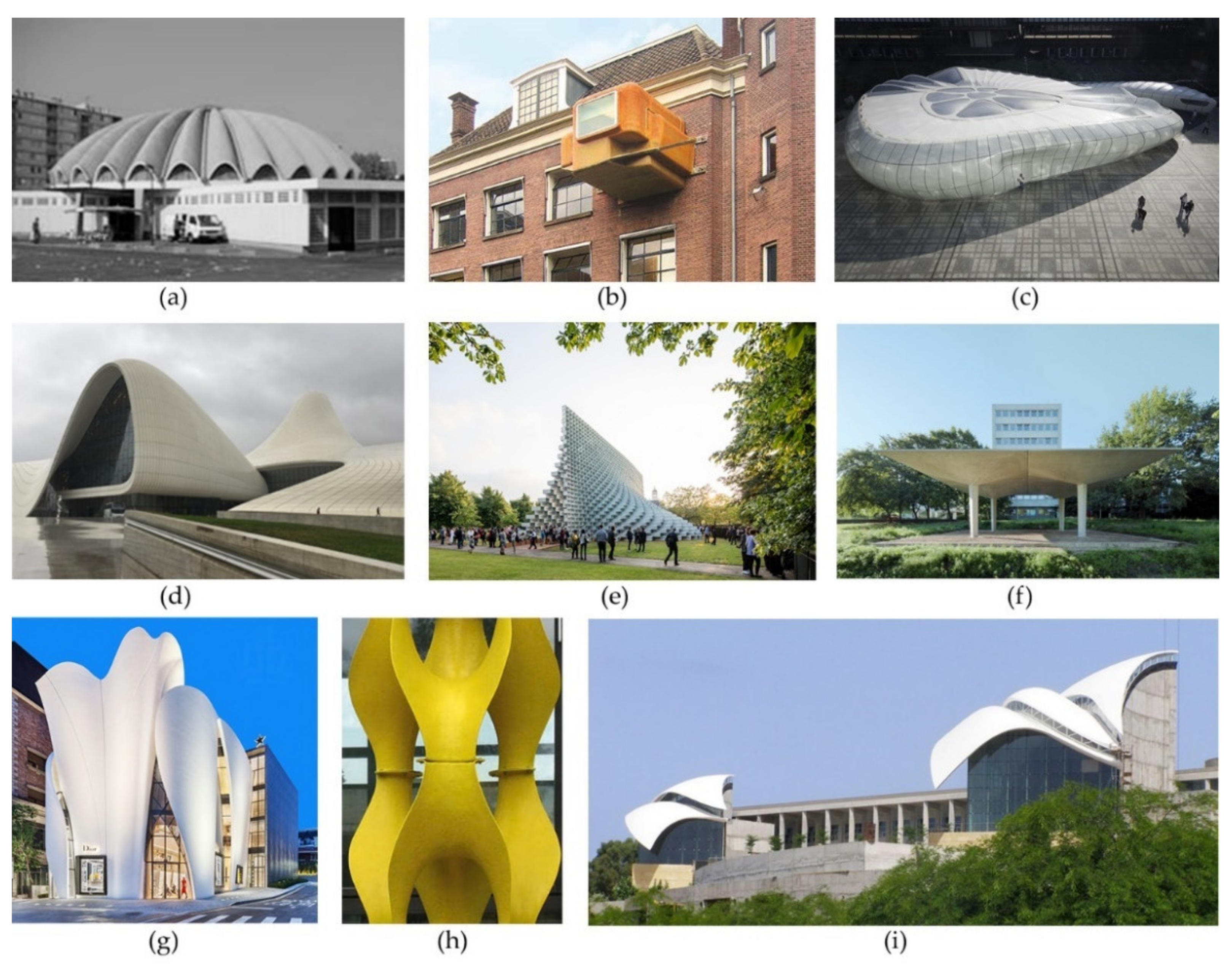
* Prices are 2016 estimates, ** Depends on the mold geometry.
Table 2. Applications of FRP composites in freeform structures in chronological order.
Name of the StructureYearLocationArchitectType of Structure, Manufacturing and Construction MethodFunction in the BuildingType of Design ApproachSource
Petrol station1962Thun, SwitzerlandHeinz IslerGFRP coffers (boxes)Roof structureGeometric approach[28]
Fly’s Eye Dome1965Three prototypes in different parts of the world;
Miami, USA (present)
Richard Buckminster FullerGFRP pre-cast module elementsSupporting structure + envelopeBiomimetic approach[150]
Market Hall1967Argenteuil, FranceStephane DuChateau30 pre-fabricated 6 mm thick GFRP shell elements mounted on a supporting tubular steel constructionRoof coveringGeometric approach[30]
The yard of the Realschule1967Geisslingen, Baden Wuerttemberg, GermanyHeinz IslerGFRP coffersRoof structureGeometric approach[61]
Futuro1968Different locations worldwideMatti SuuronenModulus CFRP sandwich elements, which form the envelope structureSupporting structure + envelopeGeometric approach[30]
Clip-On1997Utrecht, NetherlandsAtelier van Lieshout with Klaar van der LippeContinuous sandwich envelope, composed of rigid PUR panels with GFRP facing layers on both sidesSupporting structure + envelopeGeometric approach[30]
Hoofddorp bus station2003Hoofddorp, NetherlandsNIO architectenSolid PS foam structure covered by GFRP skin by spraying methodSupporting structure + envelopeGeometric approach[30]
Yitzhak Rabin Center 2005Tel Aviv, IsraelMoshe Safdie ArchitectsDouble-curved shell roof structures, made as sandwich structures with PUR core and GFRP facing layersRoof structureGeometric approach[62,63]
Lincoln Park Zoo South Pond2005Chicago, USAStudio Gang ArchitectsFiberglass pod-shape 3D panelsEnvelope Geometric approach[151]
Ljusglober2005Sweden, ÖstersundMonika GoraGFRP double-curved slicesSupporting structure + envelopeBiomimetic approach[152]
Fiberline composites factory and offices2006Middelfart, DenmarkKHR ArkitekterGFRP pultruded profiles and plates for façade and window structureEnvelopeGeometric approach[153]
Badajoz Congress Centre and Auditorium2006Badajoz, SpainSelgasCanoPultruded GFRP elliptical profiles, which form a fence-like woven structureEnvelopeGeometric approach[30]
Plastic Tower Sculpture2007Stuttgart, GermanyResearch group of Stuttgart State Academy of Art and Design Double-curved GFRP module elements, made with hand lay-up process, connected together with boltsSupporting structureGeometric approach[30,154]
Novartis campus reception building2007Basel, SwitzerlandMarco SerraSeamless sandwich slab structure with GFRP facing layers and a rigid PUR foam coreRoof structureGeometric approach[30]
Chanel Mobile Art Pavilion2010Paris, FranceZaha Hadid ArchitectsGFRP double-curved thermoformed panelsEnvelopeGeometric approach[64]
Pavilion COCOON_FS2011Jena + international, GermanyPohl ArchitectsGFRP modulus elementsSupporting structure + envelopeBiomimetic approach[96]
One Ocean, Thematic Pavilion EXPO 20122012Yeosu-si, South KoreaSOMA LimaCurved GFRP laminasFaçade shading structureBiomimetic approach[114]
Stedelijk Museum Amsterdam2012Amsterdam, NetherlandsBenthem Crouwel ArchitectsFRP seamless envelope structure with aramid and carbon fibersEnvelopeGeometric approach[155]
Heydar Aliyev Center2013Baku, AzerbaijanZaha Hadid ArchitectsGFRC and GFRP double-curved façade panelsEnvelopeGeometric approach[66]
Fletcher Hotel2013Amsterdam, NetherlandsBenthem Crouwel ArchitectsComposite curved façade elements 7 × 3.5 m, thickness 150 mm, finishing on the outside with vinyl with built-in windowsEnvelopeGeometric approach[156]
Enexis office buildings2013Maastricht, NetherlandsAtelier PROFaçade composite elements 16 × 2.8 m, with a thickness of 200 mmEnvelopeGeometric approach[157,158]
House of Dior Seoul2015Seoul, South KoreaChristian de PortzamparcSculptural free-shape façade of GFRP façade panelsEnvelopeGeometric approach[159]
ICD/ITKE Research Pavilion 2014/20152015Stuttgart, GermanyICD/ITKE research groupShell structure made by using coreless filament winding method with pneumatic formworkSupporting structure + envelopeBiomimetic approach[112]
BBVA Headquarters2015Madrid, SpainHerzog & de MeuronFRP solar protection fins Façade shading structureGeometric approach[160]
BIG’s Serpentine Gallery Pavilion2016London, Great Britain (in 2016)Vancouver, Canada (present) BIGGRFP pultruded boxesSupporting structure Geometric approach[67]
ICD/ITKE Research Pavilion 2016/20172017Stuttgart, GermanyICD/ITKE research groupCantilever shell structure made by using a multimachine fabrication system using coreless filament winding methodSupporting structure + envelopeBiomimetic approach[103]
BUGA Fibre Pavilion2019Heilbronn, GermanyICD/ITKE research groupCoreless filament windingSupporting structure Biomimetic approach[104,105]
Publisher’s Note: MDPI stays neutral with regard to jurisdictional claims in published maps and institutional affiliations.

