Article

Robustness Analysis and Important Element Evaluation Method of Truss Structures

1
Key Laboratory of C & PC Structures of Ministry of Education, National Prestress Engineering Research Center, Southeast University, Nanjing 211189, China
2
School of Aerospace, The University of Nottingham Ningbo China, No.199 Taikang East Road, Ningbo 315100, China
*
Author to whom correspondence should be addressed.
Buildings 2021, 11(10), 436; https://doi.org/10.3390/buildings11100436
Submission received: 1 August 2021 / Revised: 23 September 2021 / Accepted: 23 September 2021 / Published: 26 September 2021
(This article belongs to the Section Building Structures)

Abstract

:
Robustness and vulnerability are important evaluation criteria for structural safety to improve progressive collapse resistance. Modeling rapid evaluation on important elements in the conceptual analysis stage is an essential and efficient way to ensure the robustness of a design. This paper proposes an evaluation method for element importance by using structural strain energy, which can reflect the influence of geometric topology and external load distribution on the structural safety status simultaneously. Three simple planar trusses are chosen to clarify the proposed method. Moreover, the influences of geometric topology, boundary condition, stiffness distribution and load distribution on the element importance are investigated. This evaluation method also extends to the two spatial truss structures, regular quadrangular pyramid grid structures and chessboard-shaped pyramid grid structures. The distribution characteristics of important elements are obtained. This work defines the element importance distribution law of typical structures. It provides a method for rapid robustness analysis of general truss structures, which can be effectively integrated into the existing analysis platform.

1. Introduction

The research on the progressive collapse resistance of structures has been a hot topic worldwide for many years due to the partial or total collapse of iconic and public buildings [1,2,3,4,5,6,7,8]. There are numerous studies about the progressive collapse behavior of reinforced concrete [9,10,11,12,13] and steel frame structures [14,15,16,17]. The collapses of long-span spatial structures, especially for the spatial truss structures caused by member failure, may lead to more losses. The study of collapse behavior analysis has attracted more attention [18,19,20].
Experimental and numerical methods have been used to study the collapse behavior of long-span spatial structures. The collapse-resistant behavior of planar trusses has been investigated by experimental studies to compare the difference among the directly welded, pinned and rigid joints [21]. The snap-through collapse behavior and internal force redistribution mechanism were also understood by the experimental studies of the Kiewitt Lamella and geodesic single-layer latticed domes [22]. Progressive collapse tests have been carried out to investigate the failure mode, dynamic response and collapse mechanism of a single-layer latticed K6 dome subjected to non-uniform snow loads [3]. According to the experiment results, the internal force redistribution and the oscillatory response of truss string structures with sudden rupture of cables have also been reported [23]. The progressive collapse tests have been conducted for the single-layer cylindrical latticed shell to evaluate the effect of the joint stiffness [24].
The codified alternative path method was often introduced to perform the progressive collapse. The collapse potential would be checked by removing certain structural members by the buckling analysis and dynamical time history analysis. The equivalent load unloading method has been proposed to obtain the progressive collapse resistance capacity of long-span spatial grid structures reliably and rationally [25]. The progressive collapse resistance of double-layer grid space structures has been assessed by using both implicit and explicit methods [26]. Recently, complex physical phenomena associated with the non-elastic hysteretic behavior of bar members can be considered in the explicit dynamic analysis method to analyze the seismic collapse of spatial truss structures. The yielding under tension and buckling under compression can be included [27].
The importance evaluation of components is the basis of robustness and progressive collapse analysis. In the conceptual design stage, a rapid and efficient evaluation of element importance is important for robustness analysis, especially for the long-span spatial grid structures characterized by a high degree of static indeterminacy [15]. A safety assessment method based on a linear static analysis procedure was proposed to evaluate the sensitivity index and key index of structural members for steel truss roofs [28]. The displacement index was selected as the evaluation index of the well-formedness of single layer domes [29]. The change of smallest stiffness after removal of specific elements and the determinant of the stiffness matrix was calculated to evaluate element importance in the progressive collapse analysis of space trusses [30]. The results show that the element transferring a higher load in the load path is generally more important. Li et al. [31] proposed a new method for quantifying robustness, considering the dynamic effects and the plastic internal force redistribution within a frame structure. A suitable method for evaluating single-layer grid structures by incremental dynamic analysis, using a quantitative evaluation index called the collapse margin ratio, was established [32]. Yan et al. [33] proposed a method to identify the critical members of single-layer lattice domes, using an index that implicitly estimates the relative vulnerability to node buckling with a member removal. Static axial forces or free vibration responses were calculated and compared against the nonlinear dynamic alternate path analysis results. Element importance can be evaluated by the tangent stiffness-based method [34], which was introduced to the safety assessment of spatial truss structures, including square pyramid grids, diagonal square pyramid grids, biorthogonal lattice grids and biorthogonal diagonal lattice grids. A novel risk-based robustness index was also proposed based on the damage evolution curve [35]. The index can take into account the full spectrum of risk due to initiating events and quantify the impact of intermediate partial damages.
It should be noted that there are many indexes used to determine the important elements of structure based on the robustness, but few indexes have taken account of some factors, such as geometric topology, node connection form and external load distribution simultaneously. The structural strain energy includes both of these factors, which can reflect the structural safety status. In this paper, a new method for evaluating element importance base on structural strain energy is proposed for rapid evaluation in the conceptual analysis stage, which is an important and efficient way for the robustness design. Three types of planar trusses are chosen to calculate the important elements under the influence of the geometric topology, support conditions, stiffness distribution and external load distribution to clarify this method. Then, two kinds of spatial trusses, regular quadrangular pyramid grid structures and chessboard-shaped pyramid grid structures, were chosen to test this method.

2. Basic Principles

The equilibrium equation of an undamaged truss structure under the external load P can be given as follows:
Ku = P
where K is the global stiffness matrix, and u is the corresponding nodal displacement.
After removing the damaged elements, the equilibrium equation of the remaining structure can be modified:
K u = P ( K + Δ K ) ( u + Δ u ) = P
where K′ (K′ = K + ∆K) and u′ (u′ = u + ∆u) are the corresponding global stiffness matrix and nodal displacement of the damaged structure.
The total strain energy of the undamaged structure is denoted as V, and W represents the work of the external force. According to the law of conservation of energy, the work done by nodal loads should be equal to the accumulated strain energy.
V = W = 1 2 P Τ u = 1 2 u Τ K u
Moreover, Vi′, the strain energy of the damaged structure with removing member i, can be given by the following:
V i = 1 2 ( u + Δ u ) T ( K + Δ K ) ( u + Δ u ) = 1 2 ( u + Δ u ) T K ( u + Δ u ) + 1 2 ( u + Δ u ) T Δ K ( u + Δ u )
Substituting Equation (1) into Equation (2) leads to the following:
Δ K ( u + Δ u ) + K Δ u = 0
Substituting Equation (5) into Equation (4) can give the following:
V i = 1 2 ( u + Δ u ) Τ K u
Thus, ΔVi, the variation of the structural strain energy caused by the loss of member i, can be obtained as follows:
Δ V i = V i V = 1 2 ( u + Δ u ) Τ K u 1 2 u Τ K u = 1 2 Δ u Τ K u
After transposing both sides of Equation (5) with the orthogonal stiffness matrix, it leads to the following:
Δ u Τ K = ( u + Δ u ) Τ Δ K
Substituting Equation (8) into Equation (7) leads to the following:
Δ V i = 1 2 ( u + Δ u ) Τ Δ K u = 1 2 ( u ) Τ Δ K u
Substituting Equations (1) and (2) into Equation (9) gives the following:
Δ V i = 1 2 ( K 1 P ) Τ Δ K ( K 1 P ) = 1 2 P Τ ( K 1 ) Τ Δ K ( K 1 ) P
According to Equation (10), ΔVi is just related to the variation of structural stiffness. Therefore, ΔVi not only reflects the role of the element in the undamaged structure but also can contribute to the change of structural stiffness. The strain energy of each element in truss structures can be calculated as follows:
V ε = N 2 l 2 E A = E A ( Δ l ) 2 2 l = 1 2 σ ε v = σ 2 v 2 E = E ε 2 v 2
where N is the axial force of the bar, E is the elastic modulus of the material, l is the original length, Δl is the variation of the bar, A is the section area, ε is the strain, σ is the stress and ν is the volume. The total structural strain energy V can be obtained by adding all the strain energy of every element.

3. Element Importance Coefficient

In this paper, the proposed method is mainly used for rapid model evaluation in the conceptual analysis stage after the preliminary design of the structure. The buckling of members was avoided in the design of truss structures by controlling the geometry and axial compression force. Some assumptions are made to simplify the calculation, as well as make the investigation focused and succinct. First, only linear elasticity is considered, while material damage and structural stability are not considered. However, the geometric nonlinearity of the truss structure is considered. Second, the method of ‘conceptual removal’ (changing the topological relationship of the structure) is used in the numerical simulation for the initial damage caused by accidents without considering the dynamic effects. Third, when an accident occurs, the structure is rarely affected by earthquakes and wind loads at the same time. Therefore, only vertical loads are considered in the evaluation.
The loss of one element each time is considered in this paper. Based on the concept of sensitivity analysis, the change of the structural strain energy after the loss of elements can be used to evaluate structural robustness. Then the structural robustness coefficient, I, is defined as follows:
I = m i n i = 1 , n I i = m i n i = 1 , n 1 | 1 V ε o 1 V ε di 1 |
where o and di are the element strain energy vectors of the undamaged structure and the corresponding damaged structure with component number n, respectively.
A higher structural robustness coefficient means that loads can be distributed through more alternative paths after losing one element. If the whole structure only suffers from local damage, it can maintain its stability. Based on the fact that the structural robustness is inversely proportional to the structural sensitivity, the element importance coefficient can be derived as follows:
α i = 1 I i = | 1 V ε o 1 V ε di 1 |
where the value of αi is in [0, 1], and a larger coefficient αi represents that one element i is more important. If αi = 0, it means this element i contributes to fewer alternative load paths and is not essential in the structure.

4. Results and Discussion

4.1. Numerical Example

In this section, three planar truss structures are chosen to study the importance of elements. The software ANSYS is chosen to create models with the Link 8 element assigned with Young’s modulus E of all bars as 2.1 × 10⁵ MPa.

4.1.1. Planar Truss 1

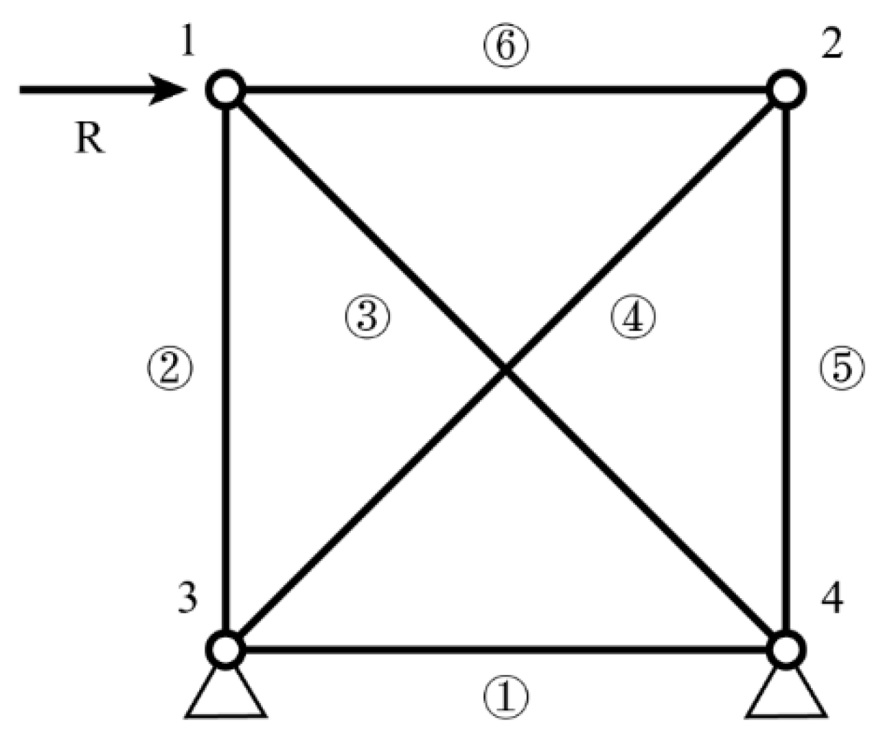
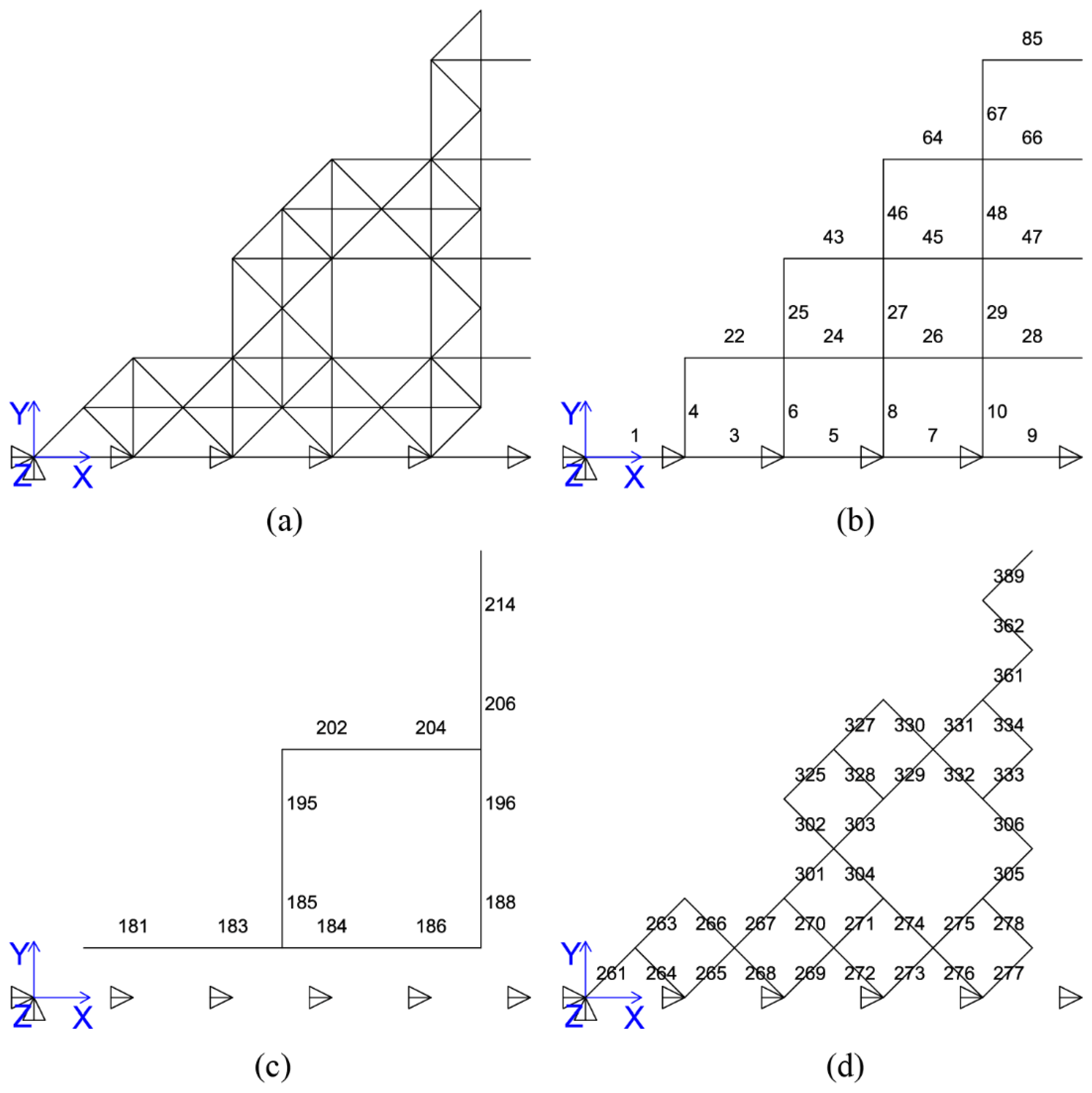
A two-dimensional truss 1 is shown in Figure 1. The height and span of the truss are both 3 m. The area of the truss section is 904 mm2 with a cross-section of Φ 76 × 4. The horizontal load applied on node 1 is 10 kN. The hinge support is used to constraint nodes 3 and 4 in the structure.
The analysis results about the element importance coefficients are given in Table 1. It can be seen that the importance coefficient of element 1 is 0, because two nodes of the element are fully restrained. Thus, these nodes have no displacement. This element does not affect the truss structure, whether it is lost or not.
The order of the importance of the elements is 2, 3→4, 5, 6→1 (the direction of the arrow indicates a decrease in the importance coefficient). The importance coefficients of elements 2 and 3 are nearly equal. From Figure 1, it can be found that a simple structure is formed by elements 2 and 3 with nodes 3 and 4. This simplified structure can support the horizontal load. Therefore, elements 2 and 3 are the most important under the load mode.
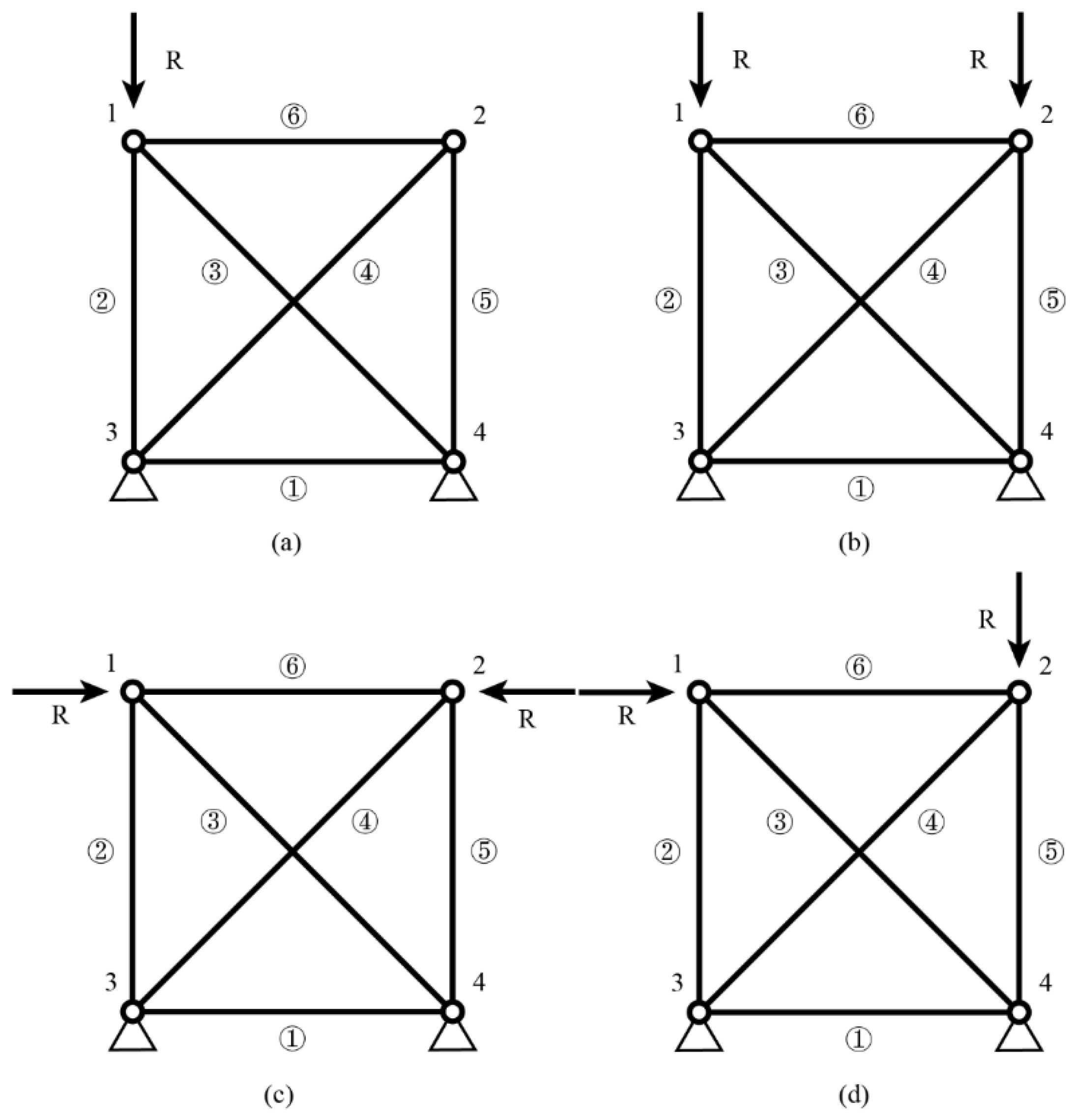
To study the effect of different load distributions on the element importance coefficient, four types of load distribution, as shown in Figure 2, are considered on the planar truss 1. It can be seen that the structural responses are not the same under different load distributions in Table 2. Under the load distribution in Figure 2a, the element importance order is 2→3, 4, 5, 6→1. Element 2 is the direct load-bearing element under this load, so it is the most important element. For load distribution in Figure 2b, the order of the element importance is 2, 5→3, 4, 6→1. Elements 2 and 5 are the main load-bearing elements, and their importance coefficients are the same, which conforms to the structural symmetry. When the structure is loaded, as shown in Figure 2c, the order of the element importance is 6→2, 5, 3, 4→1. Removing element 6 will increase the displacement of remain structure under the horizontal loads and increase element strain energy. Thus, the importance coefficient of element 6 is higher than the others. Under load distribution in Figure 2d, the order of the element importance is 5→2, 3→4, 6→1. Element 5 is the direct load-bearing element, having the highest importance coefficient. Elements 2 and 3 transfer the load of the vertical loads, which are less important.
To modify the support constraints of plane truss 1, the horizontal restriction of node 4 is removed, as shown in Figure 3b. Comparing Table 3 with Table 1, it can be seen that, when the support condition is changed, the importance coefficient of element 1 changes from 0 to 0.4999. Releasing the horizontal constraint of node 4 allows element 1 to deform under the horizontal load, and now element 1 affects the bearing load of the structure. In Figure 3b, the order of the element importance is 2, 3→4, 5, 6, 1, and each importance coefficient of elements is close. Under the condition of support II, the structure has a redundant degree of freedom, and the remaining structure will become statically determinate after removing any elements. Hence, the importance of each element is similar.
The sectional areas of elements 2–6 in Figure 1 are changed in turn to n times (Ai′ = nAi). The results about the element importance coefficient analysis are shown in Table 4. When the section of element 5 is changed, the order of the importance of the elements is 5→2, 3→4, 6→1. The importance coefficients of elements 2 and 3 are slightly different from elements 4 and 5. We can also see that the importance of element 5 increased with the area. The importance of elements 4 and 6 are also increasing, and their importance coefficients change from 0.1912 to 0.4953. Element 5 is the direct bearing loads element of the vertical loads. By increasing its sectional area, it makes elements 4 and 6 play a more important role.
Comparing the importance coefficient of each element after increasing the sectional area of element 2, we can see that there is no change in the order of the importance of the element. However, the importance coefficient of elements 2 and 3 increases from 0.501 to 0.566, and the importance coefficient of elements 5, 4 and 6 are lower than before. Similarly, in order to compare these importance coefficients after increasing the sectional area of element 3, we can see that the order of the importance of elements is not changed. The importance coefficient of elements 2 and 3 is equal to element 5. Strengthening elements 2 and 3 can improve their importance effectively and decrease the importance of elements 5, 4 and 6.
When comparing the importance coefficient of each element after increasing the sectional area of elements 4 and 6, it can be seen that there is no change in the order of the importance of the element. The importance coefficients of elements 4 and 6 have increased, and the importance coefficients of elements 5, 2 and 3 have decreased. When the sectional area of element 4 has increased, the changes of these coefficients are notable. The sectional area of element 4 is large, thus giving a high stiffness to resist large deformation. Moreover, one side of this element is linked with the fixed node, which makes node 2 no displacement. Thus, it dramatically affects the importance coefficient of whether or not to increase the sectional area of element 4. Element 6 has no constraint, such that it has little effect on the structure.
Similarly, the sectional area of element 2 is changed to n times (Ai= nAi) in Figure 2b. According to the results in Table 5, it can be found that the order of importance of the element is 2, 5→3, 4, 6→1. Along with the increase of the section of element 2, the importance of elements 2 and 5 increased, and the elements 3, 4 and 6 decreased. It should be noted that, even if the section area of element 2 is increased, it is not possible to make its importance higher than element 5 under symmetry vertical loads. When element 2 is damaged, element 5 bears no stress, resulting in the strain energy of the remaining structure being comprised only of elements 3, 4 and 6. The failure of element 5 is similar to element 2. After the failure of elements 2 and 5, the strain energy of the remaining elements is equal under the same load effect, and hence the importance of elements 2, 5 are equal. We can conclude that the structural robustness will not be improved by merely increasing the stiffness of element 2.

4.1.2. Planar Truss 2

Two-dimensional planar truss 2, shown in Figure 4, takes the height and span of all 3 m (the lengths of elements 2 and 6 are 3 m), and node 5 is the midpoint of the straight linked with nodes 3 and 4. The area of the bar section is also 904 mm2 with a cross-section of Φ 76 × 4. Node 1 is subject to a 10 kN horizontal load (R = 10 kN), and node 2 bears a 10 kN vertical load.
According to the element importance coefficient results in Table 6, the order of the element importance is 5→2→3→6→4→1→7. Due to the loss of element 1 of plane truss 1, element 5 is the immediate load-bearing member, giving it the highest importance under the vertical loads. This horizontal load is transferred to other nodes by elements linked with node 1. The importances of elements 2, 3 and 6 are higher than that of element 4, and element 1 linked to node 1 is more important than element 7. Given the same loads, because of node 5, elements 1 and 7, the importances of elements 2–5 are lower than before the structure loses one bar. There is little change of structural response, which shows overall better robustness.

4.1.3. Transient System

A transient structure can be obtained after the failure of element 3, as shown in Figure 5. The length of the elements is all 3 m, and the area of the cross-section is 904 mm2 with a cross-section of Φ 76 × 4. A vertical load P is applied on node 4, and all members are pin-jointed. The importance coefficients are shown in Table 7. The importance coefficients of elements 1 and 2 are all nearly 0, and the importance coefficient of element 3 is nearly 1 when P = 10 kN. As the load becomes higher, the importance coefficient of element 3 is lower.

4.2. Element Importance of Spatial Trusses

In this section, different grid structures are studied, including two types of spatial grids, regular quadrangular pyramid grids and chessboard-shaped pyramid grids.

4.2.1. Regular Quadrangular Pyramid Grid Structures

A regular quadrangular pyramid grid structure, as shown in Figure 6, was chosen as a case. The planar size is 40 m × 40 m. The vertical distance between the plane of top chords and lower chords is 2 m, and the material is Q235 steel with Young’s modulus 2.1 × 10⁵ MPa and the Poisson’s ratio 0.3. A dead load of 1.0 kN/m2 and a live load of 0.5 kN/m2 are applied to the upper nodes in the vertical direction. The numbers of the cross-section of elements are given in Figure 6. The details of the cross-section of elements are given in Table 8. The upper surrounding nodes are assumed to be fixed. According to the symmetry of the load and geometry, only one-eighth of the model is chosen to study the element importance, as shown in Figure 7.
Element importance coefficient results of the regular quadrangular pyramid grids are given in Table 9. The important elements of the upper chords are located near the line connecting chords 67 and 10 and are distributed in a stripe shape, while the important elements of the lower chord element are located on the lower chord plane of chord 214 and chord 188. The important elements of the web members are located near the perimeter evacuation grid of the web surface. When comparing the importance coefficients of the most important elements of each part, we see that the order of the importance coefficients is the lower chord, upper chord and then web member. Due to the decrease of the lower chords and the web members, the importance of the lower chord is increased, and the importance of the web at the edge of the evacuated grid is also increased.

4.2.2. Chessboard-Shaped Pyramid Grid Structure

A chessboard-shaped pyramid grid structure of equal bottom side length 40 m, as shown in Figure 8, was chosen as a case study. The vertical distance between the two planes or between two chords top and bottom chords is 2.0 m, and the materials are Q235 steel. Young’s modulus is 2.1 × 10⁵ MPa, and Poisson’s ratio is 0.3. The dead load is 1.0 kN/m2, and the live load is 0.5 kN/m2. The loads are applied at the upper nodes in the vertical direction. The numbers of the cross-section of elements are also given in Figure 8. Moreover, the details of the cross-section of elements are given in Table 10. The top boundary is assumed to be fixed. According to the symmetry of the load and geometry, only one-eighth of the model is chosen to study the element importance, as shown in Figure 9.
The results of the chessboard-shaped pyramid grids are given in Table 11. The important elements of the upper chord are located near the line connecting chord 67 and chord 10 and are distributed in a stripe shape. The important elements of the lower chord are distributed in a diagonal stripe, and the larger the cross-span is, the less important the element is. The important elements of the web members are located near the evacuated grid of the web surface. When comparing the importance coefficients among the most important elements of each part, we see that the order of the importance coefficients is lower chord followed by upper chord and then the least important web member. Compared to the regular quadrangular pyramid grid structure, the lower chord is rotated by 45° to increase the importance of the upper chord. The importance of the lower chord is reduced, and the importance of the web member is increased.

5. Conclusions

We proposed an evaluation method for element importance by using structural strain energy and the alternative path method. The collapse potential was assessed by the discrepancy of the strain energy through the removal of certain structural members. Three kinds of planar trusses and two types of spatial trusses were introduced to clarify the proposed method and investigate the influence of geometric topology, boundary condition, stiffness distribution and load distribution on the element importance.
For the simple planar trusses, the results show that the proposed rapid evaluation method on the element importance is useful and efficient. The order of importance of elements will change accordingly with the load distribution. Releasing support constraints can reduce the redundancy of the structure, leading to the change of importance coefficient. Increasing the section size of an element, resulting in a higher stiffness of the element, will increase the load assigned to the element under the same load, and the importance coefficients of the elements will also change.
The more redundant degrees of freedom represent how the structure has a richer force transmission path in the structure. Once the local elements of the structure are damaged, the remaining structure can rely on the adjacent elements to form a new load path so that the structure can still withstand some external load. If the failure of one element transforms the structure into a transient system, the importance coefficient of this element is much larger than that of the other elements. The results can reveal that the evaluation method of element importance is suitable.
For the spatial structure, regular quadrangular pyramid grids and chess-board-shaped pyramid grids, the distribution characteristics of important elements are investigated in upper chords, lower chords and web members. The result can provide direct guidance in component design and reinforcement for higher robustness. However, material nonlinearity and member buckling during the subsequent progressive collapse are ignored, so this proposed method is more applicable for rapid evaluation in the conceptual design of truss structures.

Author Contributions

Conceptualization, J.F. and J.C.; data curation, J.F., Y.S. and F.W.; formal analysis, Y.X. and Q.Z.; investigation, Y.S.; methodology, J.F., Y.S., F.W. and Q.Z.; validation, J.F. and Y.S.; visualization, Y.S. and J.C.; writing—original draft, J.F. All authors have read and agreed to the published version of the manuscript.

Funding

The work presented in this article was supported by the NATIONAL NATURAL SCIENCE FOUNDATION OF CHINA, grant No. 51822805, 51878147and U1937202.

Institutional Review Board Statement

Not applicable.

Informed Consent Statement

Not applicable.

Data Availability Statement

The data presented in this study are available on request from the corresponding author.

Conflicts of Interest

The authors declare no conflict of interest.

References

  1. Adam, J.M.; Parisi, F.; Sagaseta, J.; Lu, X.Z. Research and practice on progressive collapse and robustness of building structures in the 21st century. Eng. Struct. 2018, 173, 122–149. [Google Scholar] [CrossRef]
  2. Kiakojouri, F.; De Biagi, V.; Chiaia, B.; Sheidaii, M.R. Progressive collapse of framed building structures: Current knowledge and future prospects. Eng. Struct. 2020, 206, 110061. [Google Scholar] [CrossRef]
  3. Tian, L.; He, J.X.; Zhang, C.B.; Bai, R. Progressive collapse resistance of single-layer latticed domes subjected to non-uniform snow loads. J. Constr. Steel. Res. 2021, 176, 106433. [Google Scholar] [CrossRef]
  4. Mucedero, G.; Brunesi, E.; Parisi, F. Progressive collapse resistance of framed buildings with partially encased composite beams. J. Build. Eng. 2021, 38, 102228. [Google Scholar] [CrossRef]
  5. Meloni, M.; Cai, J.; Zhang, Q.; Sang-Hoon Lee, D.; Li, M.; Ma, R.; Parashkevov, T.E.; Feng, J. Engineering Origami: A comprehensive review of recent applications, design methods, and tools. Adv. Sci. 2021, 8, 2000636. [Google Scholar] [CrossRef]
  6. Zhang, Q.; Pan, N.; Meloni, M.; Lu, D.; Cai, J.; Feng, J. Reliability analysis of radially retractable roofs with revolute joint clearances. Reliab. Eng. Syst. Saf. 2021, 208, 107401. [Google Scholar] [CrossRef]
  7. Formisano, A.; Iazzetta, G.; Marino, G.; Fabbrocino, F.; Landolfo, R. Seismic residual capacity assessment of framed structures damaged by exceptional actions. In Proceedings of the 7th European Congress on Computational Methods in Applied Sciences and Engineering, Crete, Greece, 5–10 June 2016; pp. 5–10. [Google Scholar]
  8. Faggiano, B.; Formisano, A.; Mazzolani, F.M. Robustness of the Vesuvian roofs under the combined overload and high temperatures due to air falls. J. Struct. Fire Eng. 2015, 6, 213–221. [Google Scholar] [CrossRef]
  9. Qian, K.; Lan, X.; Li, Z.; Fu, F. Behavior of steel moment frames using top-and-seat angle connections under various column-removal scenarios. J. Struct. Eng. 2021, 147, 04021144. [Google Scholar] [CrossRef]
  10. Qian, K.; Lan, X.; Li, Z.; Fu, F. Effects of steel braces on robustness of steel frames against progressive collapse. J. Struct. Eng. 2021, 147, 04021180. [Google Scholar] [CrossRef]
  11. Kang, S.; Tan, K.H. Behaviour of precast concrete beam–column sub-assemblages subject to column removal. Eng. Struct. 2015, 93, 85–96. [Google Scholar] [CrossRef]
  12. Kang, S.; Tan, K.H. Robustness assessment of exterior precast concrete frames under column removal scenarios. J. Struct. Eng. 2016, 142, 0401613112. [Google Scholar] [CrossRef]
  13. Li, S.; Shan, S.; Zhai, C.; Xie, L. Experimental and numerical study on progressive collapse process of RC frames with full-height infill walls. Eng. Fail. Anal. 2016, 59, 57–68. [Google Scholar] [CrossRef]
  14. Ferraioli, M.; Lavino, A.; Mandara, A.; Donciglio, M.; Formisano, A. Seismic and robustness design of steel frame buildings. Key Eng. Mater. 2018, 763, 116–123. [Google Scholar] [CrossRef]
  15. Deng, X.F.; Liang, S.L.; Fu, F.; Qian, K. Effects of high-strength concrete on progressive collapse resistance of reinforced concrete frame. J. Struct. Eng. 2020, 146, 04020078. [Google Scholar] [CrossRef]
  16. Dinu, F.; Marginean, I.; Dubina, D. Experimental testing and numerical modelling of steel moment-frame connections under column loss. Eng. Struct. 2017, 151, 861–878. [Google Scholar] [CrossRef]
  17. Elsanadedy, H.; Alrubaidi, M.; Abbas, H.; Almusallam, T.; Al-Salloum, Y. Progressive collapse risk of 2D and 3D steel-frame assemblies having shear connections. J. Constr. Steel. Res. 2021, 179, 106533. [Google Scholar] [CrossRef]
  18. Tian, L.; Wei, J.; Hao, J. Anti-progressive collapse mechanism of long-span single-layer spatial grid structures. J. Constr. Steel. Res. 2018, 144, 270–282. [Google Scholar] [CrossRef]
  19. Wei, J.; Tian, L.; Hao, J. Improving the progressive collapse resistance of long-span single-layer spatial grid structures. Constr. Build. Mater. 2018, 171, 96–108. [Google Scholar] [CrossRef]
  20. Mohamed, O.; Khattab, R. Assessment of progressive collapse resistance of steel structures with moment resisting frames. Buildings 2019, 9, 19. [Google Scholar] [CrossRef] [Green Version]
  21. Zhao, X.; Yan, S.; Chen, Y.; Xu, Z.; Lu, Y. Experimental study on progressive collapse-resistant behavior of planar trusses. Eng. Struct. 2017, 135, 104–116. [Google Scholar] [CrossRef] [Green Version]
  22. Xu, Y.; Han, Q.H.; Parke, G.A.R.; Liu, Y.M. Experimental study and numerical simulation of the progressive collapse resistance of single-layer latticed domes. J. Struct. Eng. 2017, 143, 04017121. [Google Scholar] [CrossRef]
  23. Lu, J.; Zhang, H.; Wu, X. Experimental study on collapse behaviour of truss string structures under cable rupture. J. Constr. Steel. Res. 2021, 185, 106864. [Google Scholar] [CrossRef]
  24. Xu, Y.; Zhang, X.; Han, Q. Research on the progressive collapse resistance of single-layer cylindrical latticed shells with AH joints. Thin-Walled Struct. 2021, 158, 107178. [Google Scholar] [CrossRef]
  25. Tian, L.M.; Wei, J.P.; Hao, J.P.; Wang, X.T. Dynamic analysis method for the progressive collapse of long-span spatial grid structures. Steel Compos. Struct. 2017, 23, 435–444. [Google Scholar] [CrossRef]
  26. Fu, F.; Parke, G.A.R. Assessment of the progressive collapse resistance of double-layer grid space structures using implicit and explicit methods. Int. J. Steel Struct. 2018, 18, 831–842. [Google Scholar] [CrossRef]
  27. Zheng, H.D.; Fan, J. Analysis of the progressive collapse of space truss structures during earthquakes based on a physical theory hysteretic model. Thin-Walled Struct. 2018, 123, 70–81. [Google Scholar] [CrossRef]
  28. Jiang, X.; Chen, Y. Progressive collapse analysis and safety assessment method for steel truss roof. J. Perform. Constr. Facil. 2012, 26, 230–240. [Google Scholar] [CrossRef]
  29. Zhu, N.; Ye, J. Structural vulnerability of a single-layer dome based on its form. J. Eng. Mech. 2014, 140, 112–127. [Google Scholar] [CrossRef]
  30. Cai, J.; Jia, W.; Feng, J.; Wang, F.; Xu, Y. Applications of stiffness-based evaluation method to element importance of truss systems. J. Civ. Eng. Manag. 2017, 23, 562–572. [Google Scholar] [CrossRef]
  31. Li, L.; Li, G.; Jiang, B.; Lu, Y. Analysis of robustness of steel frames against progressive collapse. J. Constr. Steel. Res. 2018, 143, 264–278. [Google Scholar] [CrossRef] [Green Version]
  32. Tian, L.; Wei, J.; Hao, J. Method for evaluating the progressive collapse resistance of long-span single-layer spatial grid structures. Adv. Steel Constr. 2019, 15, 109–115. [Google Scholar] [CrossRef]
  33. Yan, S.; Zhao, X.; Rasmussen, K.J.R.; Zhang, H. Identification of critical members for progressive collapse analysis of single-layer latticed domes. Eng. Struct. 2019, 188, 111–120. [Google Scholar] [CrossRef]
  34. Feng, J.; Li, C.; Xu, Y.; Zhang, Q.; Wang, F.; Cai, J. Analysis of key elements of truss structures based on the tangent stiffness method. Symmetry 2020, 12, 1008. [Google Scholar] [CrossRef]
  35. Praxedes, C.; Yuan, X.X.; He, X.H.C. A novel robustness index for progressive collapse analysis of structures considering the full risk spectrum of damage evolution. Struct. Infrastruct. Eng. 2021, 2021, 1851730. [Google Scholar] [CrossRef]
Figure 1. Planar truss 1 applied by the horizontal load.
Buildings 11 00436 g001
Figure 2. Planar truss 1 under the different load distribution: (a) vertical load applied to node 1, (b) vertical loads applied to nodes 1 and 2, (c) horizontal loads applied to nodes 1 and 2 in opposite directions and (d) horizontal load applied to node 1 and vertical load applied to node 2.
Buildings 11 00436 g002
Figure 3. Planar truss 1 under different supports: (a) support I and (b) support II.
Buildings 11 00436 g003
Figure 4. Planar truss 2 under the load.
Buildings 11 00436 g004
Figure 5. Transient system.
Buildings 11 00436 g005
Figure 6. Number of cross-sections of regular quadrangular pyramid grid structure: (a) upper chords, (b) lower chords and (c) web members.
Buildings 11 00436 g006
Figure 7. Regular quadrangular pyramid grid: (a) eighth of the model, (b) number of the top chords, (c) number of the lower chords and (d) number of the diagonal web members.
Buildings 11 00436 g007
Figure 8. Number of cross-sections of chessboard-shaped pyramid grid structure: (a) upper chords, (b) lower chords and (c) web members.
Buildings 11 00436 g008
Figure 9. A chessboard-shaped pyramid grid: (a) eighth of the model, (b) number of the top chords, (c) number of the lower chords and (d) number of the diagonal web members.
Buildings 11 00436 g009
Table 1. Element importance coefficients for planar truss 1.
Structural Number123456Complete Structure
Structural strain energy1.68663.81693.81413.02373.02373.02371.6866
Element number
Element importance coefficient α i 00.55810.55780.44220.44220.4422
Table 2. Element importance coefficients for different load distributions.
Load DistributionElement Importance Coefficient
(a)00.88450.11550.11560.11560.1156
(b)00.76900.23110.23110.76900.2311
(c)00.11560.11550.11550.11560.8845
(d)00.50180.50140.19150.79600.1912
Table 3. Element importance coefficients of planar truss 1 with support II.
Structural Number123456Complete Structure
Structural strain energy3.81303.81693.81413.81283.81283.81281.9068
Element number
Element importance coefficient0.49990.50040.50010.49990.49990.4999
Table 4. Element importance coefficient on different bar sections.
Element Number
Primary structure0.50180.50140.19150.79600.1912
A5 = 10A50.49510.49490.45630.88840.4561
A5 = 50A50.49910.49890.49100.89760.4908
A5 = 100A50.49970.49950.49550.89880.4953
A2 = 100A20.56650.56610.11490.77620.1147
A3 = 100A30.74120.74100.00010.74450.0001
A4 = 100A40.31170.31140.28300.78810.2828
A6 = 100A60.44700.44670.21620.79140.2159
Table 5. Element importance coefficients with different truss sections.
Element Number
Primary structure0.76900.23110.23110.76900.2311
A2 = 10A20.85820.14190.14180.85820.1419
A2 = 100A20.86830.13190.13170.86830.1318
Table 6. Element importance coefficients of planar truss 2.
Structure Number1234567Complete Structure
Structural strain energy3.07014.94144.32283.41227.16263.44962.95182.9336
Element number
Importance coefficient 0.04450.40630.32140.14030.59040.14960.0061
Table 7. Element importance coefficient of transient system.
LoadElement Importance
P = 10 kN000.9972
P = 100 kN000.9870
P = 200 kN000.9794
Table 8. Cross-sections of elements for the regular quadrangular pyramid grid structure.
Element NumberCross-Section of ElementElement NumberCross-Section of Element
1Φ 60 × 46Φ 159 × 6
2Φ 76 × 47Φ 159 × 8
3Φ 89 × 48Φ 180 × 8
4Φ 114 × 49Φ 180 × 10
5Φ 140 × 410Φ 190 × 12
Table 9. Element Importance coefficients for regular quadrangular pyramid grid structure.
Upper Chord NumberαiLower Chord NumberαiWeb Member Numberαi
250.0158850.05692630.0144
270.03151850.04642700.0140
290.04981880.11082710.0257
450.01881950.06212770.0169
460.02411960.16082780.0470
480.04672020.06843030.0135
640.04642040.06993040.0136
660.02862060.18613050.0296
670.07942140.19763060.0299
Table 10. Cross-sections of elements for the chessboard-shaped pyramid grid structure.
Element NumberCross-Section of ElementElement NumberCross-Section of Element
1Φ 60 × 46Φ 159 × 6
2Φ 76 × 47Φ 159 × 8
3Φ 89 × 48Φ 180 × 8
4Φ 114 × 49Φ 180 × 10
5Φ 140 × 4
Table 11. Element importance coefficients for the chessboard-shaped pyramid grid.
Upper Chord NumberαiLower Chord NumberαiWeb Member Numberαi
100.0248850.10532900.0565
250.01591850.02422910.0686
270.02211890.07922920.0408
290.06252020.14163190.0690
450.03982040.06343200.0121
460.04802120.04823210.0177
480.08682130.08673220.0650
640.04482240.06593410.0208
660.06812830.02993430.0485
670.10762840.01403440.0151
Publisher’s Note: MDPI stays neutral with regard to jurisdictional claims in published maps and institutional affiliations.

