Article

Seismic Performance of Steel Structure-Foundation Systems Designed According to Eurocode 8 Provisions: The Case of Near-Fault Seismic Motions

by
Panagiota Katsimpini
1,
Foteini Konstandakopoulou
2,
George Papagiannopoulos
2,
Nikos Pnevmatikos
3 and
George Hatzigeorgiou
2,*
1
Department of Civil Engineering, University of Patras, GR-26500 Patras, Greece
2
School of Science and Technology, Hellenic Open University, GR-26335 Patras, Greece
3
Department of Civil Engineering, University of West Attica, GR-12241 Athens, Greece
*
Author to whom correspondence should be addressed.
Buildings 2020, 10(4), 63; https://doi.org/10.3390/buildings10040063
Submission received: 4 March 2020 / Revised: 21 March 2020 / Accepted: 24 March 2020 / Published: 26 March 2020
(This article belongs to the Section Building Structures)

Abstract

:
The seismic performance of steel structure-foundation systems subjected to near-fault earthquakes was assessed on the basis of response results from nonlinear time-history seismic analyses. The structural results included the maximum values for residual interstory drift ratios, base shears, and overturning moments of the steel structures, as well as the maximum values for residual settlement and tilting of the foundations. In order to reveal the influence of soil-building-interaction on the aforementioned response results, the steel building-foundation systems were designed according to Eurocode 8 provisions, assuming initially fixed and then compliant base conditions. It was concluded that for the case of near-fault seismic motions, good seismic performance of steel building-foundation hybrid systems designed according to European Codes was not guaranteed. A particular thing to note for these systems under near-fault seismic motions was that the seismic performance of the steel structure was most likely unacceptable, while one of the foundations was always acceptable.

1. Introduction

The current version of Eurocode 8 [1] considers the effects of dynamic soil-structure-interaction (SSI) to be substantial for buildings with massive foundations, pile-supported structures, slender tall buildings, and structures susceptible to second-order effects and buildings founded on very soft soils where the velocity of shear waves is less than 100 m/s. As steel structures are susceptible to second-order effects, it is implied that SSI effects should be taken into account in their design, at least when these structures are founded on very soft soils. On the other hand, regarding the SSI considerations in [1], no distinction is made between far-fault and near-fault seismic motions, even though the latter ones have been repeatedly reported in the literature to impose larger inelastic seismic demands to steel structures than the former ones. With notable exception that of the 1985 Mexico earthquake [2], the effect of SSI to steel structures subjected to far-fault seismic motions seems to be marginal. So far, only a few parametric studies have been carried out on the investigation of the effect of SSI to steel structures [3,4,5,6,7,8,9,10].
The purpose of this work was to evaluate the earthquake performance of steel structures and their foundations (termed in the following as steel-structure foundation systems), both designed in the context of Eurocode 8 [1,11,12], for the case of near-fault seismic motions. This assessment was essentially performed from an SSI point of view, accounting thus for the seismic forces and displacements induced to the steel structure-foundation systems, where the latter are mainly examined due to the stringent requirements on P-Delta effects and serviceability checks [13]. It is stressed that the current version of Eurocode 8 [11] does not propose a design procedure for steel structures under near-fault seismic motions. Therefore, not to mention SSI effects, the seismic performance of steel structures designed according to [12] for the case of near-fault seismic motions is questionable.
The assessment of the seismic performance of the steel structure-foundation systems was performed on the basis of response results from nonlinear time-history seismic analyses using SAP 2000 [14]. The structural results included the maximum values for residual interstory drift ratios (RIDR), base shears, and overturning moments of the steel structures, as well as the maximum values for residual settlement and tilting of the foundations. The permissible values for RIDR, settlement, and tilting can be found in [15,16]. In order to reveal the influence of SSI on the aforementioned response results, the steel structure-foundation systems were designed according to Eurocode 8, assuming initially fixed and then compliant base conditions. SSI was approximately included in seismic analyses, i.e., via an equivalent linear discrete model that accommodates the deformation of the foundation and the characteristics of the supporting soil. It was concluded that for the case of near-fault earthquakes, reliable seismic performance of the steel structure-foundation systems that were designed in line with the provisions of Eurocode 8 was not guaranteed. A particular thing to note for these systems under near-fault earthquakes was that the performance of the steel structure was most likely unacceptable, while one of the foundations was always acceptable.

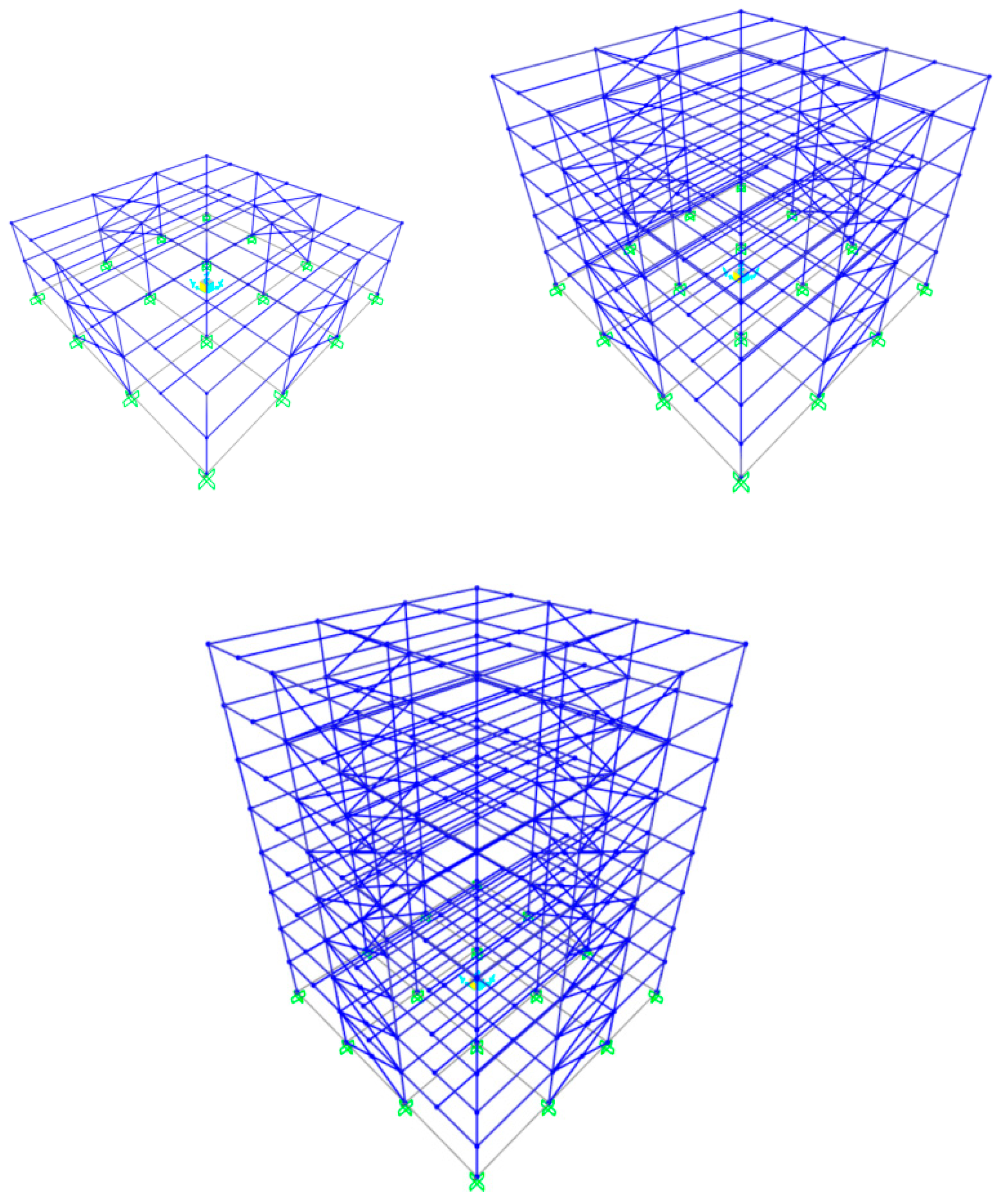
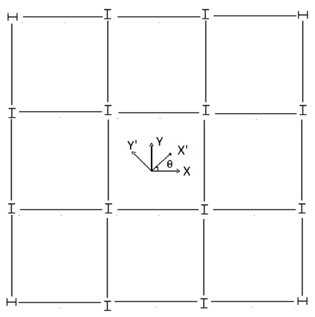
2. Seismic Analysis of Steel Structure-Foundation Systems

In this work, two-, five-, and eight-story steel buildings were investigated. Their geometry is depicted in Figure 1. These buildings had story heights of 3 m, and a square plan configuration of 18 × 18 m, i.e., three bays with an identical span of 6 m in two horizontal directions. Composite floor slabs behaved as diaphragms, assuming dead loads 8 kN/m2 and live loads 3 kN/m2. The steel buildings were designed as concentrically braced frames in association with the provisions of Eurocode 3 [17] and Eurocode 8 [11], assuming undeformable soil conditions. The steel type/grade used was S355 for columns and S275 for braces and beams. The connections for the interior-secondary beams that were not part of a frame were designed as pinned ones, while the rest of the connections involving beams and columns that were part of a frame were designed as moment-resisting ones. The steel braces intersected at their mid-length and were modeled as fixed in-plane and pinned out of plane [18]. The design earthquake forces were evaluated according to the design spectrum of Eurocode 8 [11], assuming peak ground acceleration (PGA) equal to 0.36 g, behavior factor equal to 3, and soil type B. Final sections for beams, columns, and braces are shown in Table 1. Column orientation follows Figure 2, which is commonly used for steel buildings designed as dual systems, i.e., MRF with concentric bracings [11].
A 20 × 20 m rigid-mat foundation with thickness 0.3 m, 0.6 m, and 0.8 m was designed for the two-, five-, and eight-story steel buildings, respectively. The foundation was assumed to rest on soil types B, C, and D, according to soil classification of [11]. SSI was then approximately taken into account through a discrete system of masses, dashpots, and (frequency-independent) springs, which efficiently reproduces the horizontal and vertical translations and the vertical torsional and rocking of a rigid mat foundation and its surrounding soil [19]. Even though the efficiency of the discrete system has been verified in [18], non-linear phenomena, such as uplift or slippage of the mat foundation, could not be handled. For the steel structure-foundation systems under study, inertial SSI was dominant and, thus, kinematic SSI might be omitted. The reason for omitting kinematic SSI was because the effects of base slab averaging and embedment were small for the mat foundations considered herein [20]. Moreover, the contribution of SSI to the earthquake response of the steel structure-foundation systems under study was significant for soil types C and D, whereas, for soil category B, it was marginal and could be neglected. Therefore, soil type B essentially corresponded to fixed base conditions.
The values for the masses, dashpots, and springs of the above-mentioned system were computed, employing the formulae of Table 2 [19], where G, ν, Vs are the shear modulus, Poisson’s ratio, and velocity of shear waves, respectively, of the soil medium, α is the half-length of an equivalent square foundation, m and mv are the mass of the foundation and a virtual soil mass, respectively. The soil shear modulus of soil categories C and D resulted from the corresponding velocity of shear waves, equal to 270 m/s and 180 m/s, while the soil density was assumed to be 1800 kgr/m3 and 1900 kgr/m3, respectively. Taking into account the non-linear soil deformations for soil types C and D due to relatively large values of ground acceleration, the effective shear modulus resulted from reduced values (reduction 16%) of its initial value [11].
The steel structures of Figure 1 were re-dimensioned using the design spectrum of Eurocode 8 [11], and, for soil types C and D, assuming PGA 0.36 g and behavior factor 3. The members’ sections of the steel structures constructed on soil types C and D were identical to those shown in Table 1 for soil type B (fixed base); however, the stress ratio of the sections differed for each soil type case. The first two modal periods of the steel structures of Figure 1 are shown in Table 3. Modes associated with the modal periods, presented in Table 3, exhibited a purely translational pattern for fixed base steel structures and a coupled translational-rocking pattern for steel buildings constructed on soil types C and D. The pattern of the 3rd mode (not presented in Table 3) was purely torsional in all cases.
The steel structures of Figure 1 were then subjected to non-linear time-history seismic analyses, employing the two horizontal components of the as-recorded near-fault accelerograms (seismic motions) from the 10 historical earthquakes presented in Table 4. The moment magnitude Mw of these earthquakes is also mentioned in this table. These near-fault accelerograms were applied to the two normal/horizontal axes of Figure 2, examining three values for the angle of seismic incidence θ: 0°, 45°, and 90°. It should be noted that the accelerograms of Table 4 had been recorded in the vicinity of the fault, i.e., at a distance no more than 10 km and had been produced from earthquakes of magnitude six or greater. The components of the accelerograms of Table 4 all exhibited directionality, i.e., the fault normal component was stronger than the fault parallel one. Thus, the accelerograms had been used as-recorded, and no scaling procedure had been applied to them. This was in accordance with ASCE 7–16 [20], where it is explicitly mentioned that: ‘The fault normal and the fault parallel component of the recorded near-fault motions is maintained and applied to the corresponding orientation of the structures considered’. The 5%-damped response spectra of the fault normal component of the accelerograms of Table 4, as well as the mean values of these spectra, are displayed in Figure 3. For comparison purposes, the Eurocode 8 spectra for soil types B, C, and D [11] are also provided in Figure 3.
The seismic time history analyses were performed in SAP 2000 [14], taking into account both geometrical and material non-linearities. Columns and beams were simulated using typical frame elements, assuming the concentrated plasticity approach with strain hardening 2%. For the case of beams, plastic hinges were formed as a result of uniaxial bending, while, for the case of columns, because of the complex action of axial load-biaxial bending. The restrictions for plastic rotations in the hinges were compatible with provisions of ASCE 41–17 [21]. The inherent viscous damping ratio was assumed as 3%. The ‘Link element’ of SAP 2000 [14] was used to simulate the discrete system of masses, dashpots, and springs [19] to take into account the influence of SSI on structural response. This ‘Link element’ had essentially six degrees of freedom, and the values assigned to each degree of freedom for mass, damping, and stiffness parameters are provided in Table 2. The seismic time history analyses were initially executed for the steel buildings with a fixed base where SSI was ignored, and then for the buildings constructed on the deformable ground, i.e., soil categories C or D, where SSI was considered.

3. Seismic Performance Assessment

To assess the earthquake performance of the steel building-foundation systems of Table 3 for the case of near-fault seismic motions of Table 4, the satisfaction or not of the following criteria was checked: (i) hinge rotations in columns and beams are below the life-safety target level (LS), and there is no development of a soft-story mechanism; (ii) the maximum value of the RIDR index is below 0.5% [15]; (iii) yielding of the braces occurs first and follows the expected form according to design [11]; (iv) residual settlement δ and tilting ω of the mat foundation are within the moderate damage limits of [16]. The number of failure cases regarding one or more of the aforementioned criteria indicated a high possibility of failure/collapse of the steel-structure foundation system studied.
The index R was used to reveal the effect of SSI on the seismic response of the steel building-foundation systems of Table 3. More specifically, R is defined as the ratio of RSSI to RFIX, where R is the maximum value of the following structural parameters: interstorey drift ratio (IDR), residual interstorey drift ratio (RIDR), base shear (Vb), and overturning moment (Mb). It should be noted that for the cases of soil types C and D, the net interstory displacements of the steel structures in the direction of the two horizontal -normal axes X and Y of Figure 2 were calculated, i.e., rotation of the foundation was excluded.
The seismic performance of the steel building-foundation systems was presented and discussed. Values of the index R were tabulated, and a dash (-) was denoted, where, by its definition, this index cannot be calculated. Values for Vb and Mb were provided for the two orthogonal structural axes X and Y of Figure 2. Due to the ‘Link element’ of SAP 2000 [14], the computed Vb for the SSI cases was the summation of damping and elastic forces. For the fixed base case, the Vb was the elastic force.

3.1. 2-Story Steel Structure-Foundation Systems

Table 5 reveals the number of failures for the 2-story steel structure-foundation systems when subjected to the near-fault seismic motions of Table 4, including the angle of seismic incidence θ. It was observed that the fixed base steel structures failed in total to 13 out of 30 near-fault seismic motions and θ combinations, whereas the steel structures founded on the compliant ground, i.e., on soil types C and D, did not fail. On the other hand, the mat foundation of the 2-story steel structures on compliant ground exhibited no damage. The maximum results found for settlement δ and tilting ω of the mat foundation were δ = 6.6 ∙ 10−3 (soil type C), δ = 1.56 ∙ 10−2 (soil type D), ω = 4.61 ∙ 10−4 (soil type C), and ω = 8.77 ∙ 10−4 (soil type D). Excluding the aforementioned failure cases, the maximum values of IDR and RIDR for the three values of θ are shown in Table 6, along with the corresponding values for the R index (RIDR, RRIDR). In Table 7, values for Vb, Mb, and the associated values of the R index (RVb, RMb) are presented. These Vb, Mb values were the largest ones observed for the 2-story steel structure-foundation system and came from seismic motion No.3 of Table 4 and θ = 45° incidence angle.

3.2. 5-Story Steel Structure-Foundation Systems

Table 8 reveals the number of failures for the 5-story steel structure-foundation systems when subjected to the near-fault seismic motions of Table 4, including the angle of seismic incidence θ. It was observed that out of the 30 near-fault seismic motions—θ combinations considered for each base condition, the fixed base steel structures failed to 27, whereas the steel structures with compliant base failed to 17 and 21 for soil categories C and D, respectively. However, the mat foundation of the 5-story steel buildings on soil categories C and D exhibited no damage. The maximum results found for settlement δ and tilting ω of the mat foundation were δ = 1.5 ∙ 10−2 (soil type C), δ = 3.7 ∙ 10−2 (soil type D), ω = 1.05 ∙ 10−3 (soil type C), and ω = 2.25 ∙ 10−3 (soil type D). Excluding the aforementioned failure cases, the maximum values of IDR and RIDR for the three values of θ are shown in Table 9, along with the corresponding values for the R index (RIDR, RRIDR). In Table 10, values for Vb, Mb, and the associated values of the R index (RVb, RMb) are presented. These Vb, Mb values were the largest ones observed for the 5-story steel structure-foundation system and came from seismic motion No.2 of Table 4 and θ = 90° incidence angle.

3.3. 8-Story Steel Structure-Foundation Systems

Table 11 reveals the number of failures for the 8-story steel structure-foundation systems when subjected to the near-fault seismic motions of Table 4, including the angle of seismic incidence θ. It was observed that out of the 30 near-fault seismic motions—θ combinations considered for each base condition, the fixed base steel structures failed to 28, whereas the steel structures with compliant base failed to 18 and 19 for soil categories C and D, respectively. Nevertheless, the mat foundation of the eight-story steel buildings on soil categories C and D did not fail, exhibiting either none or light damage. The maximum results found for settlement δ and tilting ω of the mat foundation were δ = 2.8 ∙ 10−2 (soil type C), δ = 6.1 ∙ 10−2 (soil type D), ω = 1.43 ∙ 10−3 (soil type C), and ω = 3.16 ∙ 10−3 (soil type D). Excluding the aforementioned failure cases, the maximum values of IDR and RIDR for the three values of θ are shown in Table 12, along with the corresponding values for the R index (RIDR, RRIDR). In Table 13, values for Vb, Mb, and the associated values of the R index (RVb, RMb) are presented. These Vb, Mb values were the largest ones observed for the 8-story steel structure-foundation system and came from seismic motion No.5 of Table 3 and θ = 90° incidence angle.

4. Discussion and Conclusions

The results presented in the previous section clearly demonstrated that the seismic performance of steel structure-foundation systems for the case of near-fault earthquake records was unfavorable for the steel structures but favorable for the foundation. In fact, in view of the smaller number of failures as Table 5, Table 8 and Table 11 witness, the steel structures in the presence of SSI (compliant base on soil types C and D) seemed to behave better than the fixed base ones.
The main type of failure observed, independent of the base conditions, was that of the creation of a soft-story mechanism at higher stories, something that, as it seemed, could not be avoided by the variation of the overstrength of the braces requirement of [11]. This type of failure is also reported by [22,23], where the seismic performance of steel braced structures under far-fault earthquakes is investigated. Therefore, as in the case of far-fault seismic motions, increased RIDRs and damage concentration were anticipated at several higher stories of steel structures designed according to [11] when these structures were subjected to near-fault seismic motions. The second type of failure observed regarding the fixed base steel structures was that of the premature yielding of a column, i.e., before the yielding of the braces. This type of failure was interpreted as a violation of the axial resistance of the column because of higher seismic design loads. Thus, for the case of near-fault earthquakes, the amplification factor of [11] for the axial force of the column because of earthquake action had to be revised.
On the other hand, the mat foundations designed according to [1] performed as expected, exhibiting in the majority of cases no damage and, in very few cases, light damage. It should be noted that when the aforementioned type of failures for the steel structures take place, the seismic performance of the foundation in terms of δ and ω is assessed up to the time point of the initiation of the failure. Nevertheless, for the case of near-fault earthquakes, the foundation design rules of [1] are considered to be adequate. However, the possible uplift and slippage of the foundation have to be further investigated, employing SSI models that can capture these non-linear phenomena.
Focusing the rest of our discussion exclusively on the seismic performance per steel structure, one concluded that the 2-story steel structures exhibited by far the best behavior. In particular, the 2-story steel structures with SSI included (soil types C and D) did not fail to any of the near-fault seismic motions of Table 4, whereas the 2-story fixed base steel structures failed to several of these motions. As inferred from the R computations presented in Table 6, the 2-story steel structures with SSI included exhibited larger values for IDR and RIDR than those with a fixed base.
The five- and eight-story fixed base steel structures failed to almost all of the near-fault seismic motions of Table 4. Along the same lines, the five- and eight-story steel buildings with SSI included (soil types C and D) failed to the majority of the near-fault seismic motions of Table 4. As inferred from the R computations presented in Table 9 and Table 12, the five- and eight-story steel structures with SSI included exhibited significantly larger values for IDR and RIDR than those with a fixed base. Therefore, it was evident that the flexibility of soil should be taken into account for the seismic analysis and design of structures since this effect could be unfavorable, leading to a more intense structural response.
Finally, the R computations of Table 7, Table 10 and Table 13 for Vb and Mb revealed either an increase or a decrease to the base shear and the overturning moment of the steel structures with SSI included (soil categories C and D) in comparison to steel structures founded on rigid soil. This variation on Vb and Mb should be further investigated in terms of an integrated performance-based seismic design approach for steel structure-foundation systems [24].

Author Contributions

All the authors have equally contributed to the conception, design, and execution of this study. The final paper has been critically revised and accepted by all the authors. All authors have read and agreed to the published version of the manuscript.

Funding

This research received no external funding.

Conflicts of Interest

The authors declare no conflict of interest.

References

  1. EN1998-5. Eurocode 8: Design of Structures for Earthquake Resistance—Part 5: Foundations, Retaining Structures and Geotechnical Aspects; European Committee for Standardization (CEN): Brussels, Belgium, 2005. [Google Scholar]
  2. Stone, W.C.; Yokel, F.Y.; Celebi, M.; Hanks, T.; Leyendecker, E.V. Engineering Aspects of the September 19, 1985 Mexico Earthquake—No. Building Science Series-165; National Institute of Standards and Technology NIST: Washington, DC, USA, 1987. [Google Scholar]
  3. Minasidis, G.; Hatzigeorgiou, G.D.; Beskos, D.E. SSI in steel frames subjected to near-fault earthquakes. Soil Dyn. Earthq. Eng. 2014, 66, 56–68. [Google Scholar] [CrossRef]
  4. Fernández Sola, L.R.; Tapia Hernández, E.; Dávalos Chávez, D. Respuesta inelástica de marcos de acero con interacción inercial suelo-estructura. Rev. Ing. Sísmica 2015, 92, 1–21. [Google Scholar] [CrossRef] [Green Version]
  5. Ayough, P.; Mohamadi, S.; Seiyed Taghia, S.A.H. Response of steel moment and braced frames subjected to near-source pulse-like ground motions by including soil-structure interaction effects. Civ. Eng. J. 2017, 3, 15–34. [Google Scholar] [CrossRef]
  6. Flogeras, A.K.; Papagiannopoulos, G.A. On the seismic response of steel buckling-restrained braced structures including soil-structure interaction. Earthq. Struct. 2017, 12, 469–478. [Google Scholar] [CrossRef]
  7. Ghandil, M.; Behnamfar, F. Ductility demands on MRF structures on soft soils considering soil-structure interaction. Soil Dyn. Eart Hquake Eng. 2017, 92, 203–214. [Google Scholar] [CrossRef]
  8. Shakib, H.; Homaei, F. Probabilistic seismic performance assessment of the soil-structure interaction effect on seismic response of mid-rise setback steel buildings. Bull. Earthq. Eng. 2017, 15, 2827–2851. [Google Scholar] [CrossRef]
  9. Farhadi, N.; Saffari, H.; Torkzadeh, P. Estimation of maximum and residual inter-storey drift in steel MRF considering soil-structure interaction from fixed-base analyses. Soil Dyn. Earthq. Eng. 2018, 114, 85–96. [Google Scholar] [CrossRef]
  10. Shahbazi, S.; Mansouri, I.; Hu, J.W.; Karami, A. Effect of soil classification on seismic behavior of SMFs considering soil-structure interaction and near-field earthquakes. Shock Vib. 2018. [Google Scholar] [CrossRef] [Green Version]
  11. EN1998-1. EEurocode 8: Design of Structures for Earthquake Resistance—Part 1: General Rules, Seismic Actions and Rules for Buildings; European Committee for Standardization (CEN): Brussels, Belgium, 2005. [Google Scholar]
  12. EN1997-1. Eurocode 7: Geotechnical Design—art 1: General rules; European Committee for Standardization (CEN): Brussels, Belgium, 2004. [Google Scholar]
  13. Tartaglia, R.; D’Aniello, M.; De Martino, A.; Di Lorenzo, G. Influence of EC8 rules on P-delta effects on the design and response of steel MRF. Inegneria Sismica Int. J. Earthq. Eng. 2018, 35, 104–120. [Google Scholar]
  14. SAP 2000. Static and Dynamic Finite Element Analysis of Structures: Version 19.0; Computers and Structures (CSI): California, CA, USA, 2016. [Google Scholar]
  15. McCormick, J.; Aburano, H.; Ikenaga, M.; Nakashima, M. Permissible residual deformation levels for building structures considering both safety and human elements. In Proceedings of the 14th World Conference on Earthquake Engineering, Beijing, China, 12–17 October 2008. [Google Scholar]
  16. Nakano, Y.; Maeda, M.; Kuramotio, H.; Murakami, M. Guideline for post-earthquake damage evaluation and rehabilitation of RC buildings in Japan. In Proceedings of the 13th World Conference on Earthquake Engineering, Vancouver, BC, Canada, 1–6 August 2004. [Google Scholar]
  17. EN1993-1. Eurocode 3: Design of Steel Structures—Part 1: General Rules and Rules for Buildings; European Committee for Standardization (CEN): Brussels, Belgium, 2009. [Google Scholar]
  18. Costanzo, S.; D’Aniello, M.; Landolfo, R. Proposal for design rules for ductile X-CBFS in the framework of Eurocode 8. Earthq. Eng. Struct. Dyn. 2019, 48, 124–151. [Google Scholar] [CrossRef] [Green Version]
  19. Mulliken, J.S.; Karabalis, D.L. Discrete model for dynamic through-the-soil coupling of 3-d foundations and structures. Earthq. Eng. Struct. Dyn. 1998, 27, 687–710. [Google Scholar] [CrossRef]
  20. ASCE 7-16. Minimum Design Loads and Associated Criteria for Buildings and Other Structures; American Society of Civil Engineers (ASCE): Reston, WV, USA, 2017. [Google Scholar]
  21. ASCE 41-17. Seismic Evaluation and Retrofit of Existing Buildings; American Society of Civil Engineers (ASCE): Reston, WV, USA, 2017. [Google Scholar]
  22. Azad, S.K.; Topkaya, C.; Astaneh-Asl, A. Seismic behavior of concentrically braced frames designed to AISC341 and EC8 provisions. J. Constr. Steel Res. 2017, 133, 383–404. [Google Scholar] [CrossRef]
  23. Costanzo, S.; Tartaglia, R.; Di Lorenzo, G.; De Martino, A. Seismic behavior of EC8-compliant moment resisting and concentrically braced frames. Buildings 2019, 9, 196. [Google Scholar] [CrossRef] [Green Version]
  24. Millen, M.D.L.; Pampanin, S.; Cubrinovski, M.; Carr, A. Integrating soil-structure interaction within performance-based design. In Proceedings of the Annual Technical Conference of the New Zealand Society for Earthquake Engineering, Auckland, New Zealand, 21–23 March 2014. [Google Scholar]
Figure 1. Two-, five-, and eight-story steel buildings.
Buildings 10 00063 g001
Figure 2. The orientation of columns for the 2-, 5-, and 8-story steel buildings.
Buildings 10 00063 g002
Figure 3. Response spectra of the accelerograms of Table 3 and of Eurocode 8 [11].
Buildings 10 00063 g003
Table 1. Sections of steel beams, braces, and columns.
Steel StructureBeamsBracesColumns
2-storyIPE 450CHS 219.1 × 5.0HEM 320
5-storyIPE 500CHS 273.0 × 5.6HEM 600
8-storyIPE 500CHS 355.6 × 6.3HEM 700
Table 2. Formulae for mass, springs, and dashpots (after [19]).
Mass (Inertia) Ratio, βEquivalent Radius, r0Virtual Soil Mass (Inertia), mvStatic Stiffness KDamping C
Vertical ( 1 ν ) 4 m ρ r 0 3 2 a π 0.27 m β 4.7 G a 1 ν 0.8 a V s K
Horizontal ( 7 8 ν ) 32 ( 1 ν ) m ρ r 0 3 2 a π 0.095 m β 9.2 G a 2 ν 0.163 a V s K
Rocking 3 ( 1 ν ) 8 m ρ r 0 5 2 a 3 π 4 0.24 m β 4.0 G α 3 1 ν 0.6 a V s K
Torsion m ρ r 0 5 2 a 3 π 4 0.045 m β 8.31 G α 3 0.127 a V s K
Table 3. Modal periods of buildings under consideration.
Steel Structure1st Mode (s)2nd Mode (s)
2-story, soil type B (fixed base)0.2540.236
2-story, soil category C0.5690.546
2-story, soil category D0.6000.578
5-story, soil type B (fixed base)0.5230.474
5-story, soil category C1.2641.169
5-story, soil category D1.3421.283
8-story, soil type B (fixed base)0.8000.749
8-story, soil category C1.2891.180
8-story, soil category D1.4291.333
Table 4. Near-fault accelerograms considered.
No.Earthquake, Location, YearRecording StationMw
1.San Fernando, (Calif.), 1971Pacoima Dam6.6
2.Superstition Hills, (Calif.), 1987Parachute Test Site7.3
3.Loma Prieta, (Calif.), 1989Los Gatos6.5
4.Cape Mendocino, (Calif.), 1992Petrolia7.0
5.Landers, (Calif.), 1992Lucerne Valley7.3
6.Northridge, (Calif.), 1994Rinaldi Receiving St.6.7
7.Northridge, (Calif.), 1994Newhall6.7
8.Northridge, (Calif.), 1994Sylmar Converter St.6.7
9.Kobe, Japan, 1995Takatori6.9
10.Christchurch, New Zealand, 2011Resthaven6.3
Table 5. The number of failures for the 2-story steel structure-foundation systems.
Steel Structure-Foundation, θNumber of Failures - Steel StructureNumber of Failures - Foundation
2-story, fixed, 0°4/10-
2-story, fixed, 45°4/10-
2-story, fixed, 90°5/10-
2-story, soil type C, 0°0/100/10
2-story, soil type C, 45°0/100/10
2-story, soil type C, 90°0/100/10
2-story, soil type D, 0°0/100/10
2-story, soil type D, 45°0/100/10
2-story, soil type D, 90°0/100/10
Table 6. Maximum IDR, RIDR, and R values of the 2-story steel structure-foundation systems.
Steel Structure-Foundation, θIDR (%)RIDR (%)RIDRRRIDR
2-story, fixed, 0°0.620.28--
2-story, fixed, 45°0.520.13--
2-story, fixed, 90°0.520.07--
2-story, soil type C, 0°3.220.255.190.89
2-story, soil type C, 45°3.330.256.401.92
2-story, soil type C, 90°2.500.164.812.29
2-story, soil type D, 0°3.500.395.641.39
2-story, soil type D, 45°3.410.236.561.77
2-story, soil type D, 90°2.460.134.731.86
Table 7. Maximum Vb, Mb, and R values of the 2-story steel structure-foundation systems.
Steel Structure-FoundationVb (kN)Mb (kNm)RVbRMb
2-story, fixed7222 (X)
6923 (Y)
34,740 (X)
36,950 (Y)
--
2-story, soil type C6720 (X)
7633 (Y)
47,220 (X)
48,740 (Y)
0.93 (X)
1.10 (Y)
1.36 (X)
1.32 (Y)
2-story, soil type D5575 (X)
8219 (Y)
51,130 (X)
38,750 (Y)
0.77 (X)
1.19 (Y)
1.47 (X)
1.05 (Y)
Table 8. The number of failures for the 5-story steel structure-foundation systems.
Steel Structure-Foundation, θNumber of Failures - Steel StructureNumber of Failures - Foundation
5-story, fixed, 0°9/10-
5-story, fixed, 45°9/10-
5-story, fixed, 90°9/10-
5-story, soil type C, 0°5/100/10
5-story, soil type C, 45°6/100/10
5-story, soil type C, 90°6/100/10
5-story, soil type D, 0°7/100/10
5-story, soil type D, 45°7/100/10
5-story, soil type D, 90°7/100/10
Table 9. Maximum IDR, RIDR, and R values of the 5-story steel structure-foundation systems.
Steel Structure-Foundation, θIDR (%)RIDR (%)RIDRRRIDR
5-story, fixed, 0°0.510.08--
5-story, fixed, 45°0.670.05--
5-story, fixed, 90°0.730.04--
5-story, soil type C, 0°2.100.254.123.13
5-story, soil type C, 45°2.220.443.318.80
5-story, soil type C, 90°2.690.333.688.25
5-story, soil type D, 0°3.170.186.222.25
5-story, soil type D, 45°2.380.243.554.80
5-story, soil type D, 90°2.570.413.5210.25
Table 10. Maximum Vb, Mb, and R values of the 5-story steel structure-foundation systems.
Steel Structure-FoundationVb (kN)Mb (kNm)RVbRMb
5-story, fixed9216 (X)
8192 (Y)
96,750 (X)
102,100 (Y)
--
5-story, soil type C8588 (X)
12,960 (Y)
112,300 (X)
86,640 (Y)
0.93 (X)
1.58 (Y)
1.16 (X)
0.85 (Y)
5-story, soil type D5920 (X)
12,820 (Y)
111,500 (X)
71,460 (Y)
0.64 (X)
1.56 (Y)
1.15 (X)
0.70 (Y)
Table 11. The number of failures for the 8-story steel structure-foundation systems.
Steel Structure-Foundation, θNumber of Failures - Steel StructureNumber of Failures - Foundation
8-story, fixed, 0°9/10-
8-story, fixed, 45°9/10-
8-story, fixed, 90°10/10-
8-story, soil type C, 0°6/100/10
8-story, soil type C, 45°6/100/10
8-story, soil type C, 90°6/100/10
8-story, soil type D, 0°5/100/10
8-story, soil type D, 45°7/100/10
8-story, soil type D, 90°7/100/10
Table 12. Maximum IDR, RIDR, and R values of the 8-story steel structure-foundation systems.
Steel Structure-Foundation, θIDR (%)RIDR (%)RIDRRRIDR
8-story, fixed, 0°0.690.05--
8-story, fixed, 45°0.700.06--
8-story, fixed, 90°0.700.06--
8-story, soil type C, 0°2.100.123.042.40
8-story, soil type C, 45°2.190.213.133.50
8-story, soil type C, 90°2.620.313.745.17
8-story, soil type D, 0°3.350.214.863.50
8-story, soil type D, 45°3.350.384.796.33
8-story, soil type D, 90°3.270.494.678.17
Table 13. Maximum Vb, Mb, and R values of the 8-story steel structure-foundation systems.
Steel Structure-FoundationVb (kN)Mb (kNm)RVbRMb
8-story, fixed17,280 (X)
8748 (Y)
121,800 (X)
240,900 (Y)
--
8-story, soil type C18,000 (X)
7868 (Y)
80,650 (X)
170,700 (Y)
1.04 (X)
0.90 (Y)
0.66 (X)
0.71 (Y)
8-story, soil type D15,450 (X)
6024 (Y)
58,780 (X)
173,500 (Y)
0.89 (X)
0.69 (Y)
0.48 (X)
0.72 (Y)

