In-Plane Shear Resistance between the Rammed Earth Blocks with Simple Interventions: Experimentation and Finite Element Study


Abstract
1. Introduction
2. Specimen and Materials
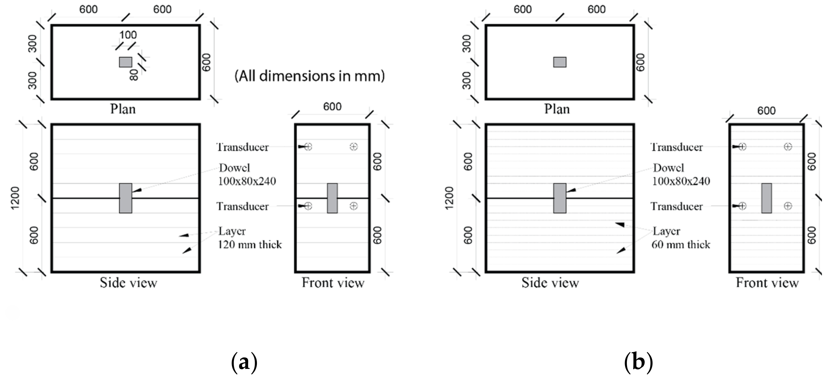
2.1. Specimen
2.2. Material
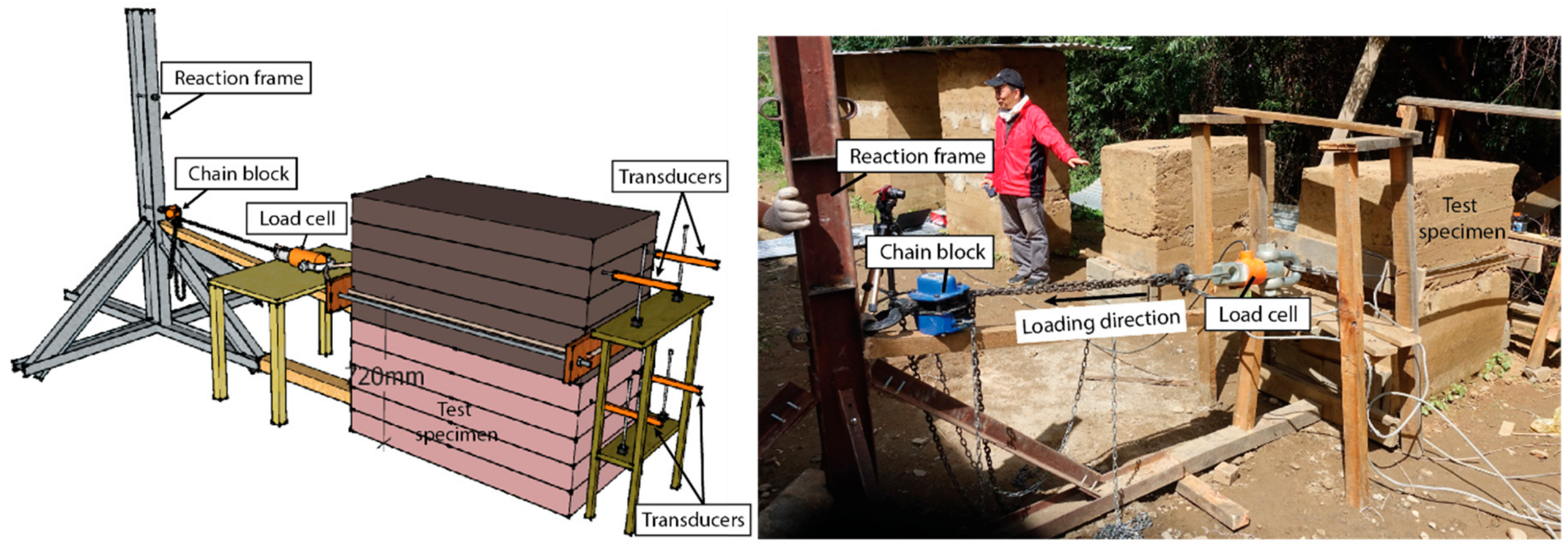
3. Test Set–Up
4. Finite Element Modeling
4.1. Rammed Earth Block
4.2. Reinforced Concrete Dowel
4.3. Rammed Earth Block Interface
5. Results and Discussion
5.1. Shear Test Results
5.2. Theoretical Formulation
5.3. FE Simulation Results
6. Conclusions
- A slight increment, about 12%, in strength characteristics for RE blocks was observed when the layer thickness decreased from 120 mm to 60 mm at 1 month of drying. This increment was reduced to about 2.6% for 6 months’ dried specimen.
- The specimens gained strength with drying. There was about 120% increment in compressive strength for specimen after 6 months of drying over the one dried for 1 month.
- An enhancement in the load carrying capacity of around 29% for reinforced TEST–R120 over unreinforced TEST–U120 was observed. There was about 12.3% increment in strength for TEST–R60 over TEST–R120 with the change in the RE layer thickness. A simple insertion of RC dowel at the RE block interface effectively delayed the initiation of slip along the interface joint and enhanced the shear strength characteristics.
- The FE simulation predicted the test observations reasonably well for unreinforced as well as reinforced specimens. The sensitivity studies showed negligible effect of interfacial stiffness and tensile strength on shear strength characteristics. On the other hand, cohesion and friction angle properties of RE interface are critical parameters for shear behavior in RE walls.
Author Contributions
Funding
Acknowledgments
Conflicts of Interest
References
- Jaquin, P.A.; Augarde, C.E.; Gerrard, C.M. Chronological description of the spatial development of rammed earth techniques. Int. J. Arch. Herit. 2008, 2, 377–400. [Google Scholar] [CrossRef]
- Hall, M.; Djerbib, Y. Rammed earth sample production: Context, recommendations and consistency. Constr. Build. Mater. 2004, 18, 281–286. [Google Scholar] [CrossRef]
- Hodson, T. Innovations in rammed earth construction, Western Australia. Struct. Eng. 2006, 84, 30–36. [Google Scholar]
- Walker, P.; Keable, R.; Martin, J.; Maniatidis, V. Rammed Earth: Design and Construction Guidelines; BRE Press: London, UK, 2005. [Google Scholar]
- Liu, K.; Wang, M.; Wang, Y. Seismic retrofitting of rural rammed earth buildings using externally bonded fibers. Constr. Build. Mater. 2015, 100, 91–101. [Google Scholar] [CrossRef]
- Bui, Q.B.; Morel, J.C.; Reddy, B.V.V.; Ghayad, W. Durability of rammed earth walls exposed for 20 years to natural weathering. Build. Environ. 2009, 44, 912–919. [Google Scholar] [CrossRef]
- Bui, Q.B.; Hans, S.; Morel, J.C.; Do, A.P. First exploratory study on dynamic characteristics of rammed earth buildings. Eng. Struct. 2011, 33, 3690–3695. [Google Scholar] [CrossRef]
- Wang, Y.; Wang, M.; Liu, K.; Pan, W.; Yang, X. Shaking table tests on seismic retrofitting of rammed–earth structures. Bull. Earthq. Eng. 2016, 15, 1037–1055. [Google Scholar] [CrossRef]
- UNESCO. Report on Consultation Meeting on the Implementation of the World Heritage Earthen Architecture Programme (WHEAP) in the Arab States–Strategies and Approaches; United Nations Educational, Scientific and Cultural Organization: Paris, France, 2010; Available online: https://whc.unesco.org/document/107242 (accessed on 2 February 2020).
- UNESCO. World Heritage Inventory of Earthen Architecture. World Heritage Earthen Architecture Programme, CRAterre–ENSAG.. 2012. Available online: https://unesdoc.unesco.org/ark:/48223/pf0000217020 (accessed on 2 February 2020).
- Bui, T.T.; Bui, Q.B.; Limam, A.; Maximilien, S. Failure of rammed earth walls: From observations to quantifications. Constr. Build. Mater. 2013, 51, 295–302. [Google Scholar] [CrossRef]
- Cheah, J.S.; Morgan, T.K.K.B.; Ingham, J.M. Cyclic testing of a full–size stablized, flax–fibre reinforced earth (Uku) wall system with openings. In Proceedings of the The 14th World Conference on Earthquake Engineering, Beijing, China, 12–17 October 2008. [Google Scholar]
- Miccoli, L.; Muller, U.; Pospisil, S. Rammed earth walls strengthened with polyester fabric strips: Experimental analysis under in–plane cyclic loading. Constr. Build. Mater. 2017, 149, 29–36. [Google Scholar] [CrossRef]
- Fagone, M.; Kloft, H.; Loccarini, F.; Ranocchiai, G. Jute fabric as a reinforcement for rammed earth structures. Compos. Part B Eng. 2019, 175, 107064. [Google Scholar] [CrossRef]
- Pang, M.; Yang, S.; Zhang, Y. Experimental study of cement mortar–steel fiber reinforced rammed earth wall. Sustainability 2012, 4, 2630–2638. [Google Scholar] [CrossRef]
- Hamilton, H.R.; McBride, J.; Grill, J. Cyclic testing of rammed–earth walls containing post–tensioned reinforcement. Earthq. Spectra 2006, 22, 937–959. [Google Scholar] [CrossRef]
- Zhou, T.; Liu, B. Experimental study on the shaking table tests of a modern inner–reinforced rammed earth structure. Constr. Build. Mater. 2019, 203, 567–578. [Google Scholar] [CrossRef]
- Shrestha, K.C.; Aoki, T.; Konishi, T.; Miyamoto, M.; Zhang, J.; Takahashi, N.; Wangmo, P.; Aramaki, T.; Yuasa, N. Full-scale pull-down tests on a two-storied rammed earth building with possible strengthening interventions. In Structural Analysis of Historical Constructions; Aguilar, R., Torrealva, D., Moreira, S., Pando, M.A., Ramos, L.F., Eds.; RILEM Bookseries; Springer: Basel, Switzerland, 2019; Volume 18, pp. 1557–1565. [Google Scholar] [CrossRef]
- Shrestha, K.C.; Aoki, T.; Miyamoto, M.; Wangmo, P.; Pema; Zhang, J.; Takahashi, N. Strengthening of rammed earth structures with simple interventions. J. Build. Eng. 2020, 29, 101179. [Google Scholar] [CrossRef]
- JIS A 1204. Test Method for Particle Size Distribution of Soils; Japan Industrial Standard: Tokyo, Japan, 2009. [Google Scholar]
- ASTM C39/C39M–17b. Standard Test Method for Compressive Strength of Cylindrical Concrete Specimens; ASTM International: West Conshohocken, PA, USA, 2017. [Google Scholar] [CrossRef]
- ASTM C496/C496–17. Standard Test Method for Splitting Tensile Strength of Cylindrical Concrete Specimens; ASTM International: West Conshohocken, PA, USA, 2017. [Google Scholar] [CrossRef]
- DIANA. User’s Manual Release 10.1; DIANA FEA BV: Delft, The Netherlands, 2017. [Google Scholar]
- Lourenco, P.B.; Rots, J.G. Multisurface interface model for analysis of masonry structures. ASCE J. Eng. Mech. 1997, 123, 660–668. [Google Scholar] [CrossRef]
- Shrestha, K.C.; Pareek, S.; Suzuki, Y.; Araki, Y. Pinning retrofit technique in masonry with application of polymer–cement pastes as bonding agents. Earthq. Struct. Int. J. 2013, 5, 477–497. [Google Scholar] [CrossRef]
- Shrestha, K.C.; Nagae, T.; Araki, Y. Finite element modeling of cyclic out–of–plane response of masonry walls retrofitted by inserting inclined stainless steel bars. J. Dis. Res. 2011, 6, 36–43. [Google Scholar] [CrossRef]
- Wangmo, P.; Shrestha, K.C.; Miyamoto, M.; Aoki, T. Assessment of out–of–plane behaviour of rammed earth walls by pull–down tests. Int. J. Arch. Herit. 2019, 13, 273–287. [Google Scholar] [CrossRef]
- Bui, T.L.; Bui, T.T.; Bui, Q.B.; Nguyen, X.H.; Limam, A. Out-of-plane behavior of rammed earth walls under seismic loading: Finite element simulation. Structures 2020, 24, 191–208. [Google Scholar] [CrossRef]
- Cheah, J.S.J.; Walker, P.; Heath, A.; Morgan, T.K.K.B. Evaluating shear test methods for stabilized rammed earth. Constr. Mater. 2012, 165, 325–334. [Google Scholar] [CrossRef]
- El-Nabouch, R.; Bui, Q.B.; Ple, O.; Perrotin, P. Characterizing the shear parameters of rammed earth material by using a full-scale direct shear box. Constr. Build. Mater. 2018, 171, 414–420. [Google Scholar] [CrossRef]
- Miccoli, L.; Drougkas, A.; Muller, U. In–plane behaviour of rammed earth under cyclic loading: Experimental testing and finite element modeling. Eng. Struct. 2016, 125, 144–152. [Google Scholar] [CrossRef]
- Miccoli, L.; Oliviera, D.V.; Silva, R.A.; Muller, U.; Schueremans, L. Static behaviour of rammed earth: Experimental testing and finite element modelling. Mater. Struct. 2014, 48, 3443–3456. [Google Scholar] [CrossRef]


| Rammed Earth Layer Thickness—Drying Period | Bulk Density (kg/m3) | Compressive Strength (MPa) | Tensile Strength (MPa) | Elastic Modulus (MPa) | ||||
|---|---|---|---|---|---|---|---|---|
| Mean | Std. Dev. | Mean | Std. Dev. | Mean | Std. Dev. | Mean | Std. Dev. | |
| 120 mm—1 month | 1918 | 50 | 0.50 | 0.07 | 0.06 | 0.006 | 59.96 | 8.6 |
| 60 mm—1 month | 1985 | 32 | 0.56 | 0.04 | 0.11 | 0.006 | 66.76 | 27.2 |
| 120 mm—6 months | 2060 | 10 | 1.15 | 0.05 | – | – | 255.5 | 47.1 |
| 60 mm—6 months | 2080 | 17 | 1.18 | 0.08 | – | – | 186.5 | 74.5 |
| Material Properties | RE Layer 120 mm (FE–U120/FE–R120) | RE Layer 60 mm (FE–R60) | |
|---|---|---|---|
| Mass Density, ρr (kg/m3) | 1918 | 1985 | |
| Poisson’s ratio, ν | 0.15 | 0.15 | |
| Elastic modulus, Er (MPa) | 60 | 67 | |
| Tensile strength, ft (MPa) | 0.06 | 0.11 | |
| Mode–I tensile fracture energy, GfI (N/mm) | 0.005 | 0.01 | |
| Compressive strength, fc (MPa) | 0.50 | 0.56 | |
| Compressive fracture energy, Gc (N/mm) | 0.79 | 0.84 | |
| RE block Interface properties | Normal stiffness, knz (N/mm3) | 150 | 150 |
| Shear stiffness, ksx (N/mm3) | 75 | 75 | |
| Shear stiffness, ksy (N/mm3) | 75 | 75 | |
| Cohesion, c (MPa) | 0.008 | 0.008 | |
| Friction angle, tanϕ | 0.8 | 0.8 | |
| Dilatancy angle, tanψ | 0 | 0 | |
| Tensile strength, fti (MPa) | 0.004 | 0.004 | |
| Stiffness, ksx, ksy | Cohesion, c | Tensile Strength, fti | Friction Angle, tanϕ | |||||||||||||
|---|---|---|---|---|---|---|---|---|---|---|---|---|---|---|---|---|
| Change (%) | 20 | −20 | 40 | −40 | 20 | −20 | 40 | −40 | 20 | −20 | 40 | −40 | 13 | −13 | 19 | −19 |
| FE–ID | 1 | 2 | 3 | 4 | 5 | 6 | 7 | 8 | 9 | 10 | 11 | 12 | 13 | 14 | 15 | 16 |
© 2020 by the authors. Licensee MDPI, Basel, Switzerland. This article is an open access article distributed under the terms and conditions of the Creative Commons Attribution (CC BY) license (http://creativecommons.org/licenses/by/4.0/).
Share and Cite
Shrestha, K.C.; Aoki, T.; Miyamoto, M.; Wangmo, P.; Pema. In-Plane Shear Resistance between the Rammed Earth Blocks with Simple Interventions: Experimentation and Finite Element Study. Buildings 2020, 10, 57. https://doi.org/10.3390/buildings10030057
Shrestha KC, Aoki T, Miyamoto M, Wangmo P, Pema. In-Plane Shear Resistance between the Rammed Earth Blocks with Simple Interventions: Experimentation and Finite Element Study. Buildings. 2020; 10(3):57. https://doi.org/10.3390/buildings10030057
Chicago/Turabian StyleShrestha, Kshitij C., Takayoshi Aoki, Mitsuhiro Miyamoto, Phuntsho Wangmo, and Pema. 2020. "In-Plane Shear Resistance between the Rammed Earth Blocks with Simple Interventions: Experimentation and Finite Element Study" Buildings 10, no. 3: 57. https://doi.org/10.3390/buildings10030057
APA StyleShrestha, K. C., Aoki, T., Miyamoto, M., Wangmo, P., & Pema. (2020). In-Plane Shear Resistance between the Rammed Earth Blocks with Simple Interventions: Experimentation and Finite Element Study. Buildings, 10(3), 57. https://doi.org/10.3390/buildings10030057