Article

The Impacts of Air Leakage Paths and Airtightness Levels on Air Change Rates

by
Vitor E. M. Cardoso
1,*,
Pedro F. Pereira
1,
Nuno M. M. Ramos
1 and
Ricardo M. S. F. Almeida
1,2
1
Institute of R&D in Structures and Construction (CONSTRUCT), Laboratory of Building Physics (LFC), Faculdade de Engenharia (FEUP), Universidade do Porto, Rua Dr. Roberto Frias s/n, 4200-465 Porto, Portugal
2
Polytechnic Institute of Viseu, School of Technology and Management, Department of Civil Engineering, Campus Politécnico de Repeses, 3504-510 Viseu, Portugal
*
Author to whom correspondence should be addressed.
Buildings 2020, 10(3), 55; https://doi.org/10.3390/buildings10030055
Submission received: 7 February 2020 / Revised: 29 February 2020 / Accepted: 9 March 2020 / Published: 12 March 2020

Abstract

:
Southern European countries have milder climatic conditions that differ from their colder northern counterparts, which greatly influence indoor ventilation strategies. The relation between a building’s airtightness and the air change rates remains a topic to be fully tackled in these countries, since natural ventilation is very frequent. In this work, the ventilation and airtightness of a case study were analyzed in-depth to support a discussion on this topic. CO2 concentration decay and blower-door measurements were used to characterize the infiltration and ventilation conditions of the case study. The case study represents a common Portuguese situation, with highly permeable envelopes, combined with highly variable air change rates. Transient simulations were carried out for the comparison of scenarios where different configurations of possible air paths were analyzed. The simulations included both natural and mechanical ventilation scenarios. An air sweeping effect from bedroom to bathroom only occurred when the mechanical extraction ventilation (MEV) was on. Different air leakage path configurations resulted in substantial offsets, up to 63%, of the air change rate (ACH) due to natural occurring forces. The results confirmed that the relation between airtightness and air change rates should be carefully analyzed in southern European countries, as indoor air quality, comfort of occupants, and energy efficiency are highly influenced by the considered variables.

1. Introduction

The energy consumption on heating and cooling of EU buildings and industries represents about 50% of the total EU energy consumption [1]. In the residential sector, space heating accounts for 78% of the total energy consumption [2], and single-family houses have a final energy demand over two times higher than multifamily houses. The UCD Research Group estimates that, in Central European countries, ventilation contributes with between 20% and 40% to the total losses accounted for [3]. In line with these findings, Liddament and Orme [4] report a contribution of thermal losses through ventilation in the order of 36% of the total energy required for heating interior spaces.
In the 1970s, when energy savings became increasingly necessary, several air infiltration mitigation measures occurred. Several countries have imposed in their national legislation, limits for the airtightness value. The most used parameter to quantify the airtightness is the air change per hour at a pressure difference of 50 Pa between the interior and the exterior (ACH50). The maximum accepted ACH50 is usually set according to the ventilation strategy or other factors, such as dwelling typology. In Southern European countries, such as Portugal and Greece, the legislation regarding the building airtightness is not as restrictive as it is in the Northern European countries. Although components’ performances, e.g., that of windows, is required, and the inclusion of an ACH50 measurement is possible, no mandatory limits on residential whole building airtightness are set in the most up to date energy efficiency legislation that transposed the 2010/31/EU directive [5].
Since Southern European countries have climate conditions influencing indoor ventilation that differ from their northern counterparts, the legislation regarding this issue should be adapted for these countries. Some studies are tackling the problem of finding the optimum ACH50 [6]. Some of the main issues on the establishing optimum ACH50 encompass: the granting of a range that ensures minimum air change rates for health reasons (i.e., removal of pollutants) and stability on that level, since as air change rates have an impact on energy consumption, high levels are to be avoided: the discussion of operating ranges of mechanical equipment and their relation with building airtightness levels. This work contributes to filling gaps in the understanding of these issues, with a case study in the Southern European climate and simulation scenarios, by assessing:
  • The impacts of different configurations of air leakage paths on air change rate (ACH);
  • The effect of changing airtightness levels on the air change rates provided by mechanical ventilation.

2. State of the Art

2.1. Ventilation of Buildings

One of the primary functions of a building is to provide an adequate indoor environment for the occupants. Amongst other variables, one can only maintain a healthy indoor environment with adequate indoor air quality (IAQ) [7]. The air flows into and out of a building through pressure differentials across the envelope air paths. The purposeful withdrawal and admission of air into a building refers to ventilation, which subdivides into adventitious, natural, mechanical, and hybrid ventilation [8,9].
Air changes through unintentional background leakages refers as infiltration, when the airflow is from the outdoors into the building, and as exfiltration the other way around. Together they are referred solely as air leakage. The air leakage rate through a building envelope is dependent on: the size and distribution of air leakage paths, the flow characteristics of the leakage paths, and the pressure difference across the leakage paths [10].
The occurring natural forces that induce pressure differentials in building envelopes are the wind and the air temperature differences between the indoor and outdoor air (thermal buoyancy). The mechanical forces comprise operating ventilation fans. Thermal buoyancy is stronger with increasing temperature differences between the inside and the outside of an envelope and in taller buildings [11]. Wind pressure on surfaces strongly depends on its direction, speed, air density, surface orientation, and surrounding conditions [12]. The wind effect dominates natural ventilation systems when wind speeds are higher than 3 m/s [13].
The two mechanisms do not act independently, and thus cannot be simply summed after separate calculations. Their combined effect is never higher than the one resulting from the straight addition of the effects alone [14]. The quadrature superposition was shown to be a robust approach [15]. Their interaction is not only influenced by the distribution of intentional and unintentional air paths on the building enclosure but also by building geometry and irregularities in the flow itself. For stable effects of wind and buoyancy, different distribution patterns of air admission can cancel or add to each other. Inclusion of pressure regulators in the ventilation openings and designing fans for high enough pressures are among the most common actions to minimize abnormal wind and stack pressures, in order to obtain more reliable and stable air change rates.

2.2. Airtightness and Air Change Rates

Since air infiltration is unintentional, the quantification of its contribution is challenging to appropriately address in the design phase of a ventilation system. In leakier building envelopes, higher and less stable airflow volumes tend to occur. Therefore, ventilation strategies have distinct relationships with air permeability performance. Liddament [16] studied those relationships and proposed performance ranges, shown in Table 1.
Natural ventilation, either with or without point extraction, has more significant performance variability than mechanical ventilation. Because of that fact, the leakiness of envelopes on buildings with natural ventilation systems does not need to be as limited as for buildings with mechanical ones, particularly the ones with air handling units (AHU), such as heat recovery devices.
The resistance to inward or outward air leakage through unintentional leakage points in the building envelope is frequently defined as airtightness [17]. It takes the form of a flow rate for a given reference pressure divided by a building scale metric. When assessing airtightness, the reference metric for the air pressure difference is often 50 Pa. However, other values can be applied, such as 75, 25, 10, 4, and 1 Pa. The building size scaling is, commonly, the building volume, the envelope area, or the floor area [18]. Building volume is useful because the normalization results in air changes per hour (ACH) at the reference pressure. Envelope area is notably valuable for attached buildings, where only part of the conditioned space limits is in contact with outdoor conditions. The floor area is practical, as it is the closest agreement with usable living space.
Addressing airtightness is an important issue both for new and existing buildings [19]. Table 2 indicates the airtightness requirements for residential buildings according to several codes of European countries. To normalize the criteria to the same parameter, ACH50, a pressure exponent, n = 0.67, and a structure with a typical volume of 300 m3 and a surface area of 250 m2, were assumed [20]. There is a trend for more demanding airtightness requirements/recommendations in countries with severely cold climates. On the other hand, southern European countries commonly overlook this issue, and building codes do not have mandatory building airtightness requirements.
Airtightness measurements are theoretically not dependent on climatic conditions, since their calculations rely on inducing pressure differences high enough to neglect the effect of natural pressure variations across the building envelope. On that behalf, airtightness is the most useful property for the air leakage characterization and comparison of existing buildings. It is also broadly used in the modeling and quality control of new constructions and the assessment of interventions in the built environment [18].
In-situ blower-door tests are the most common way of assessing building airtightness. A pressurization/depressurization procedure of the building is implemented during these tests, allowing one to assess the resultant air flow. The power-law (Equation (1)) is the equation used to describe building airtightness by several standards, such as ISO 9972:2015 [23]. Although other forms, such as a quadratic law, exist [24], theoretical analysis, laboratory measurements, and field tests assure the power law to be the most accurate in describing the real conditions producing better results at low pressures [25].
Q = c   ( Δ p ) n
where:
Q—airflow through opening (m3/s);
c—flow coefficient (m3/(s·Pan));
Δp—pressure difference (Pa);
n—pressure exponent (-).
Despite being an essential parameter for the envelope characterization, airtightness measurements do not represent the actual air change rates of buildings. Extrapolation is necessary for infiltration values in pressure levels corresponding to those induced by natural conditions [26]. A standard method for the determination of ACH is the use of tracer gases. According to ASTM-E741 [27], the calculation of hourly air changes can follow three different test methods: concentration decay, constant injection, and constant concentration. The literature indicates that the most consensual method for the calculation of the ACH is the concentration decay test method [27,28,29]. This method bases itself on the fact that for the typical situation within a room, with constant temperature and wind (almost constant airflow) and well-mixed air, the mass balance of the tracer gas can be expressed by Equation (2).
V × dC ( t ) dt = G + Q × C ext Q × C ( t )   ,
where:
V—room volume (m3);
C(t)—interior concentration of the tracer gas in the time interval t (ppm);
t—time (s);
G—interior production of the tracer gas (cm3/s);
Q—air changes between the interior and the exterior (m3/s);
Cext—exterior concentration of the tracer gas (ppm).
For the calculation of the ACH, during the periods where there is tracer gas production in the room, the solution of the mass balance equation can be used, but the least-squares method is also required. The desirable properties for a tracer gas can be found in the literature, and different types of gases can be used, although none meets all the requirements. Metabolic CO2 is considered a good option as a tracer gas [30,31].

2.3. Infiltration Modeling

Another form of evaluating air change rates is the use of modeling software. Air infiltration modeling is a fundamental tool, which can be applied both for new building design and for existing building retrofitting. It contributes to the prediction of air change rates, indoor climate, energy-efficient conditioning and ventilation system conception, and lastly, initial and running costs [32]. An accurate calculation of the air infiltration requires data on [9,33]: the wind speed and direction at a desired location; indoor and outdoor air temperatures; the position and flow characteristics of all openings and cracks in the envelope; the pressure distribution product of the climatic influence on the driving mechanism; and the topography characteristics of the terrain at the building location.
Infiltration models range from empirical to theoretical. The first deal with pressure data reduction [34], the statistical characterization of a built stock [35], and lastly, single component assessments [36]. Theoretical models stretch from single-zone [37] to multi-zone [38], and from computational fluid dynamics (CFD) coupling [39] to full CFD [40]. The latter, while achieving more accurate results, comes at the expense of a clearer and truer discretization and increased computational power and time [41]. Accuracy issues regarding data on building leakage distribution, internal and external geometry properties, and weather, are at the most common bases of the uncertainty [42]. Although infiltration modeling is dependent on several assumptions and simplifications, it serves as a tool for scenario comparison and estimations of performance.
Zone modeling has the advantage of defining the simulation directly with clear calculation procedures, but since detailed airflow, temperature, and pressure distributions in each zone are unknown, an integrated macro and micro approach to the modeling effort is needed, if increased prediction accuracy on the referred variables simulation is to be achieved [43]. Weather data, such as wind pressure coefficients (Cp), require a similar approach. These are available from direct measurements [44], databases [45], and analytical models [46], among others, and the output of simulation scenarios shows considerable variation when different sources are used [47].

3. Materials and Methods

3.1. Case Study, Measurements, and Equipment

The assessment of the ventilation performance of the case study took place in the months of July and August. The case study was an apartment in Porto, Portugal. The apartment has mechanical extraction ventilation (MEV) with air exhaust in the bathrooms and kitchen. The air supply takes place through unintentional air leakage paths. Two compartments of the case study (Figure 1 and Table 3) were monitored using nondispersive infrared (NDIR) sensors to measure the CO2 concentration (Table 4). During the measurement campaign, the door connecting the bedroom to the rest of the apartment remained shut when not in use.
The ACH value of the compartments was determined considering the concentration decay test method using the occupant-generated CO2 as a tracer gas. The ACH value was determined for different ventilation configurations in standard conditions of use: with MEV on and MEV off. When MEV is on, it has a maximum extraction volume of 98 m3/h. The CO2 production estimation was calculated based on the methodology proposed by Coley and Beisteiner [31]. The average night production of CO2 was 5.97 cm3/s. The value used for the external CO2 concentration was the one indicated in ASTM-D6245 [48], 350 ppm. An on-site outdoor CO2 monitoring campaign validated this value for two weeks, with an average value of 348 ppm. The ACH values were calculated daily during the two months, taking into account the recommendation stated in the standard ASTM-E741 [27].
According to Bekö et al. [49], this technique estimates the total airflow into the studied room (total air exchange rate), including airflows from adjacent ones, and not only the outdoor air exchange rate. The same authors [50] found that these errors average 30%.
Blower-door measurements were made to determine the compartments ACH50 with a Retrotec Model 1000 fan [51], coupled with a DM-2 gauge [52]. The accuracies of the equipment are ±3% of the reading, and ±1% or 0.15 Pa (whichever is greater), respectively.
The ACH50 of the compartments was determined by applying the method A of the standard EN 13829 [53]. Both depressurization and pressurization tests were undertaken to a pressure difference of 50 Pa. The final ACH50 is the average of those individual results.

3.2. Simulation Scenarios

An in-depth analysis of the case study was performed using numerical simulation. The selection of the software considered the following points, according to the recommendations stated by Orme and Leksmono [36]:
  • The application of multizone modeling, since two zones were modelled—the bedroom and the adjacent bathroom;
  • The input of structured data related to climate and weather, such as long-term meteorological data files [54], air leakage characteristics, from component airtightness databases [55], and wind pressure coefficients, in the form of fully developed profiles [56];
  • The modelling of air handling systems, since mechanical ventilation is present in the bathroom.
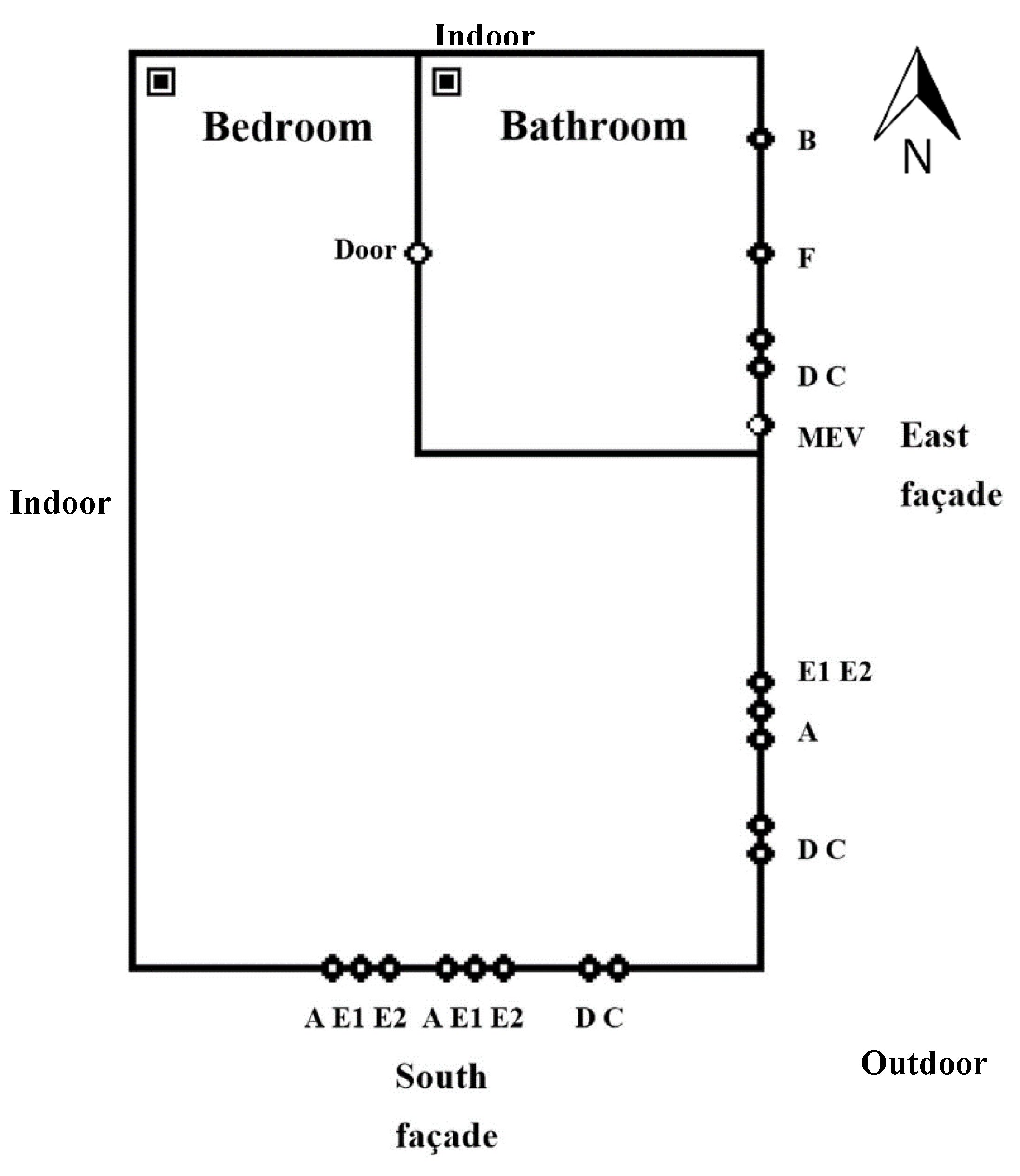
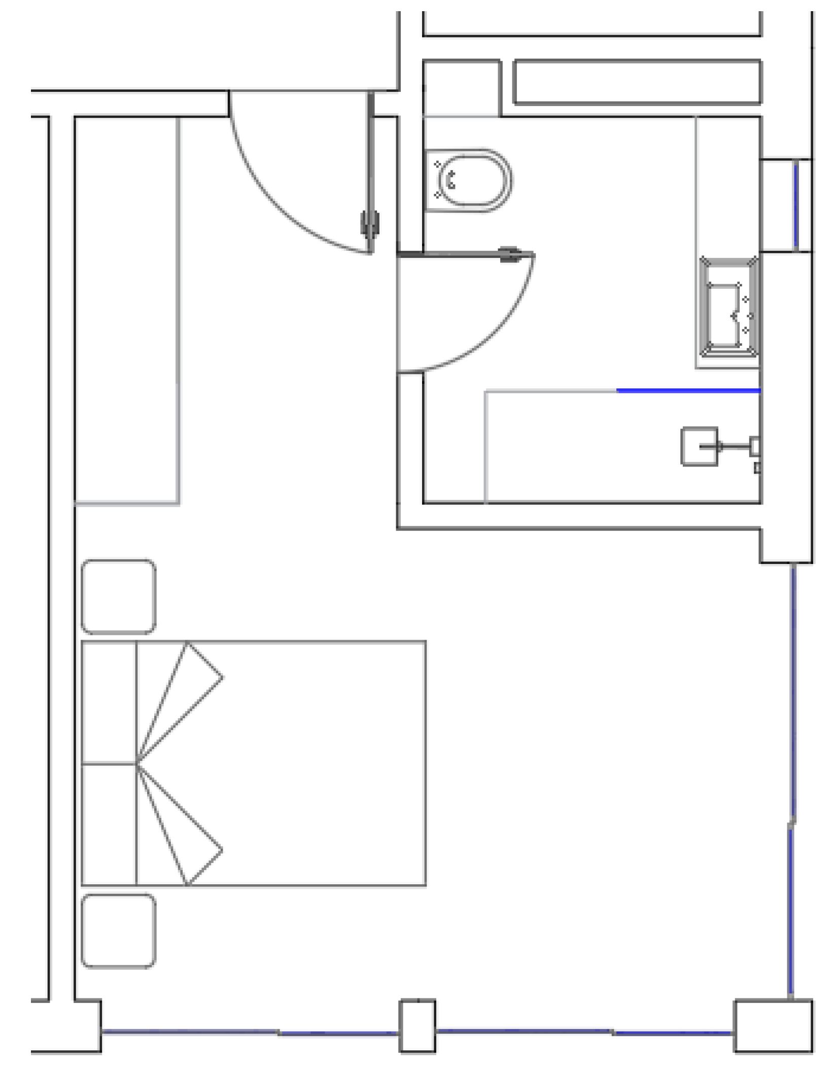
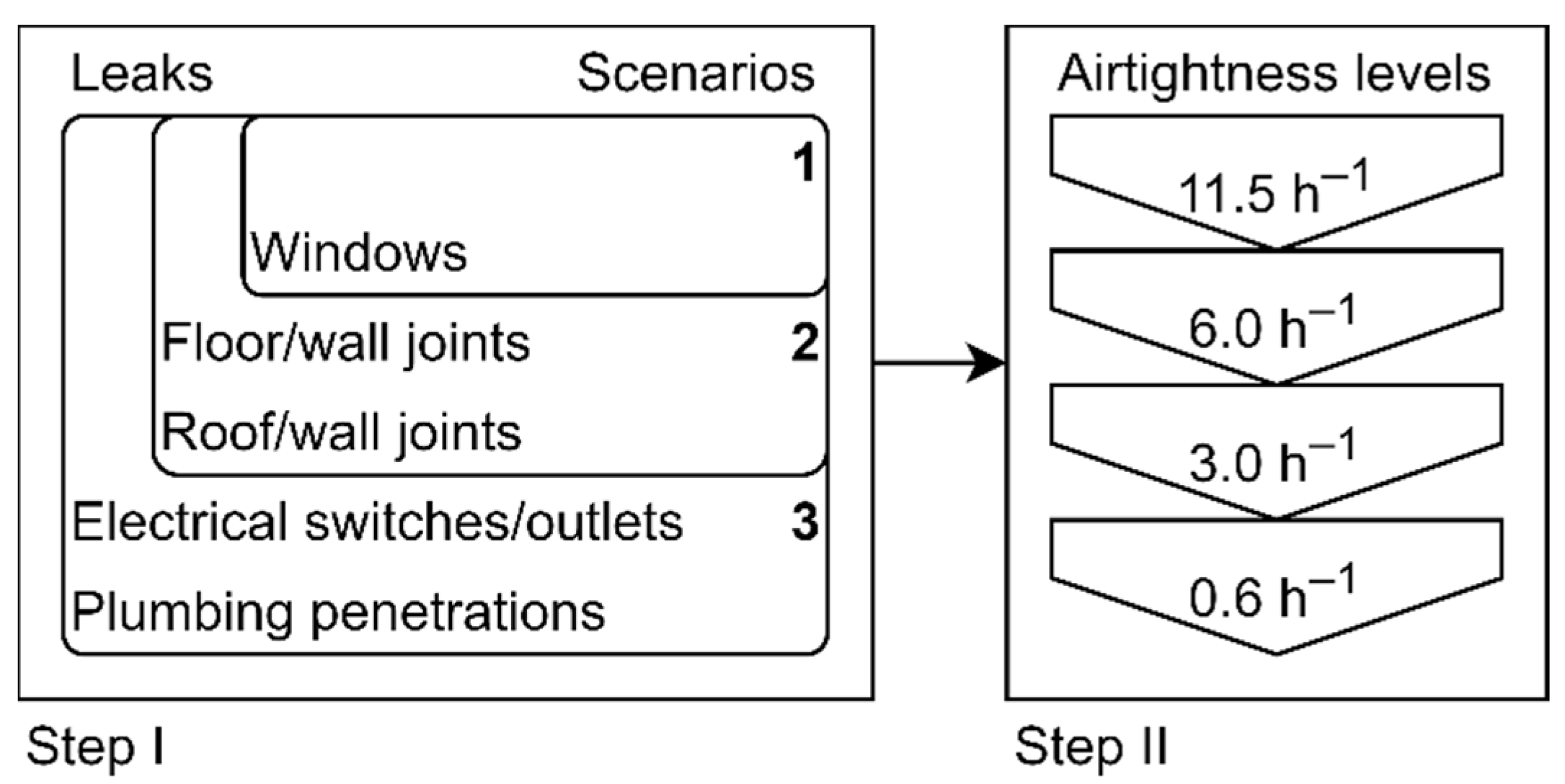
The CONTAM software [57] was chosen, since it fulfils all these conditions. It is often used for the modelling of ventilation strategies and energy impacts [58] and contaminant dispersion [59]. This software also enables importing data from several sources, easing the creation and comparison of scenarios. Figure 2 presents a plan on the ones considered.
  • Step I: Changing air leakage paths configurations
In order to assess the impact of air leakage distribution on the ACH, three scenarios were modeled, all of them assuming the same airtightness level. The scenarios vary in the number of types of air leakage paths and assume that MEV is off. In Scenario 1, only the windows are considered. Scenario 2 encompasses windows, and joints of floor/wall and roof/wall. Lastly, Scenario 3 encompasses all of the air leakage path types of Scenario 2, plus electrical switches and outlets, and plumbing penetrations. The focus on the construction of these scenarios is the progressive shifting from a concentrated infiltration to a more disperse one.
  • Step II: Changing airtightness levels
Changing the ACH50, and therefore altering the total effective leakage area (ELA), enables evaluating the impact on the ACH, both with and without mechanical extraction (MEV). For that, using the three modeled scenarios to assess changing air leakage paths configurations, four levels of ACH50 were assumed for modeling, each resulting from a different source based on: the blower-door measurement, 11.5 h−1; a mid-range requirement for dwellings with natural ventilation, 6.0 h−1; a mid-range requirement for dwellings with mechanical extraction ventilation [16], 3.0 h−1; the passive house requirement on airtightness [60], 0.6 h−1.
The intention of using a case study and measurements was to have results on the performance of a real setup and to use those results as input data for a simulation. Simulating with this input data allows for the comparison with measurements results, supporting a partial validation of the assumed discretization and additional trust in simulation results for the other equated scenarios.

3.3. Input Data and Methodology

As most of the leakage paths are located randomly, in a real case, it is an almost impossible task to address each leakage path individually and identify its respective characteristics. Construction quality, manufacturing, and installation processes influence the characteristics of leakage paths [61]. For that reason, when dealing with these input data, commonly, extensive libraries of effective leakage areas (ELAs) on typified air leakage paths are used, such as the ones present in ASHRAE [62] and AIVC [45].
In this particular work, as individual leakage characteristics are not known, a total ELA was calculated. An ELA is the area of a circular sharped edge orifice that would leak the same volume of air as a particular tested specimen when pressurized to a reference pressure difference [63]. In other words, it represents an overall quantitative effect of the airflow paths. The three scenarios [62] that are being analyzed assume the measured airflow of 50 Pa for both compartments. The total ELA is thus calculated from that airflow volume (Equation (3)), and, as such, it is the same for the three scenarios [62]. The discharge coefficient for this case study was assumed as 1.0, typical of small openings.
ELA r = 10000 Q r ρ / 2 Δ p r C D
where:
ELAr—equivalent or effective air leakage area at a reference pressure difference (cm2);
Qr—predicted airflow rate at Δpr (m3/s);
ρ—air density (kg/m3);
Δpr—reference pressure difference (Pa);
CD—discharge coefficient (-).
In order to apply a relative weight to the contribution of each type of leak to the overall performance, the libraries available on the website of National Institute of Standards and Technology (NIST) were used to quantify the airflow value of the elements [55]. As all the values suggested in those libraries are based on a pressure difference of 4 Pa, the calculated total ELA needs to be converted (4). The values are also based in a discharge coefficient of 1.0 and an airflow exponent of 0.65.
A r , 2 = A r , 1 C D , 1 C D , 2 ( Δ p r , 2 Δ p r , 1 ) n 0.5
where:
Ar,i—air leakage area at reference pressure difference Δpr,i (cm2);
CD,i—discharge coefficient used to calculate Ar,i (-);
n—pressure exponent (-).
The ELAs in these libraries are normalized by an interface metric (usually area, length, or item), meaning that only by multiplying it, does one get the entire ELA of a specific air leakage path ( ELA r , i ) (5). Table 5 presents the types of air leakage paths used in the simulation of the three scenarios and their respective normalized ELAs. In order to maintain the proportionality, and henceforth, the airtightness level to be the same in all scenarios, the transformation shown in (Equation (6)) must be made.
ELA r , i = ELA r , n · I
ELA r , p , i = ELA r , total · ELA r , i i = 1 j ELA r , i
where:
ELAr,i —effective leakage area at a reference pressure difference of type i air leakage path (cm2);
ELAr,n—effective leakage area at a reference pressure difference normalized by an interface (cm2/metric);
I—interface metric of a type of air leakage path (usually m2, m, item);
ELAr,p,i—proportional effective leakage area at a reference pressure difference of type i air leakage path (cm2);
ELAr,total—effective leakage area at a reference pressure difference based on measurement results (cm2)
The ELA of a particular type of air leakage path (ELAr,p,i) varies between scenarios, as the increasing consideration of additional types of leakage changes the relative contribution of each ELA (Table 6). Air leakage interface metric indicates the extension of the leakage, linear meters (m) or the number of items, and envelope orientation is either south or east. Figure 3 illustrates the model of the scenario with the highest number of types of air leakage paths (scenario 3). The mechanical extractor (MEV) in the bathroom is also included.
The door connecting the two compartments has a cross-sectional area of 1.4 m2 and is considered open in the simulations. For all the other openings, since they are assumed as small, the discharge coefficient and the flow exponent assume the values defined in the ASHRAE libraries [55].
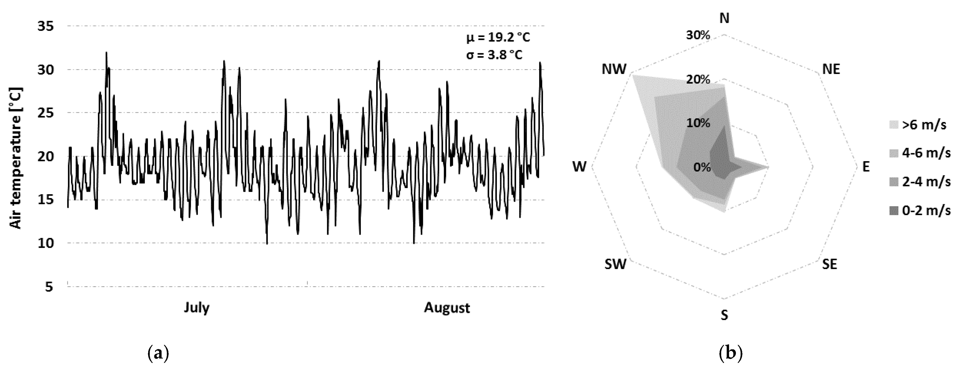
The simulation period followed the same time period of the measurement campaign, July–August. Hourly averaged air temperature as well as wind speed and direction were obtained by the spatial interpolation of public weather data [54] (Figure 4). The wind pressure coefficients were estimated using the methodology proposed by Swami and Chandra [56]. The performance data of the extraction fan of the bathroom were provided by the manufacturer.
The uncertainty on measurement results and the discretization for simulation, such as in weather data, wind pressure coefficients, and air leakage characteristics, is not insignificant. Still, since the considered scenarios have fairly disparate boundaries, the comparison of results between them will not be hindered by these factors. Therefore, best estimates of measurement results were considered, and coherently, best estimate values of the considered library on effective leakage areas were also admitted.
4. Results and Discussion

4.1. Measurements

Table 7 presents the results of the blower-door test (ACH50) and the tracer gas measurements (ACH) carried out in the two compartments separately.
With MEV on, the ACH of bedroom and bathroom reaches 0.78 h−1, and 4.21 h−1, with the overall renovations standing at 1.52 h−1. This value is the result of volume averaging.
Minimum ACH for indoor air quality in residential buildings often range from 0.4 to 0.8 h−1, when the MEV is off the results are particularly low, 0.13 h−1 and 0.15 h−1, for the bathroom and the bedroom, respectively. The ACH50 was measured for the ensemble of the two compartments and 11.5 h−1, in line with the upper values obtained in the study of Ramos et al [64].
With this airtightness level one would expect the ACH to be higher that measured, as the literature defends [65]. The most likely reason for this phenomenon is the fact that the case study has envelope facing south and east and the most predominant wind directions are north, northwest and west.

4.2. Step I: Effect of Air Leakage Distribution in Natural Ventilation Conditions

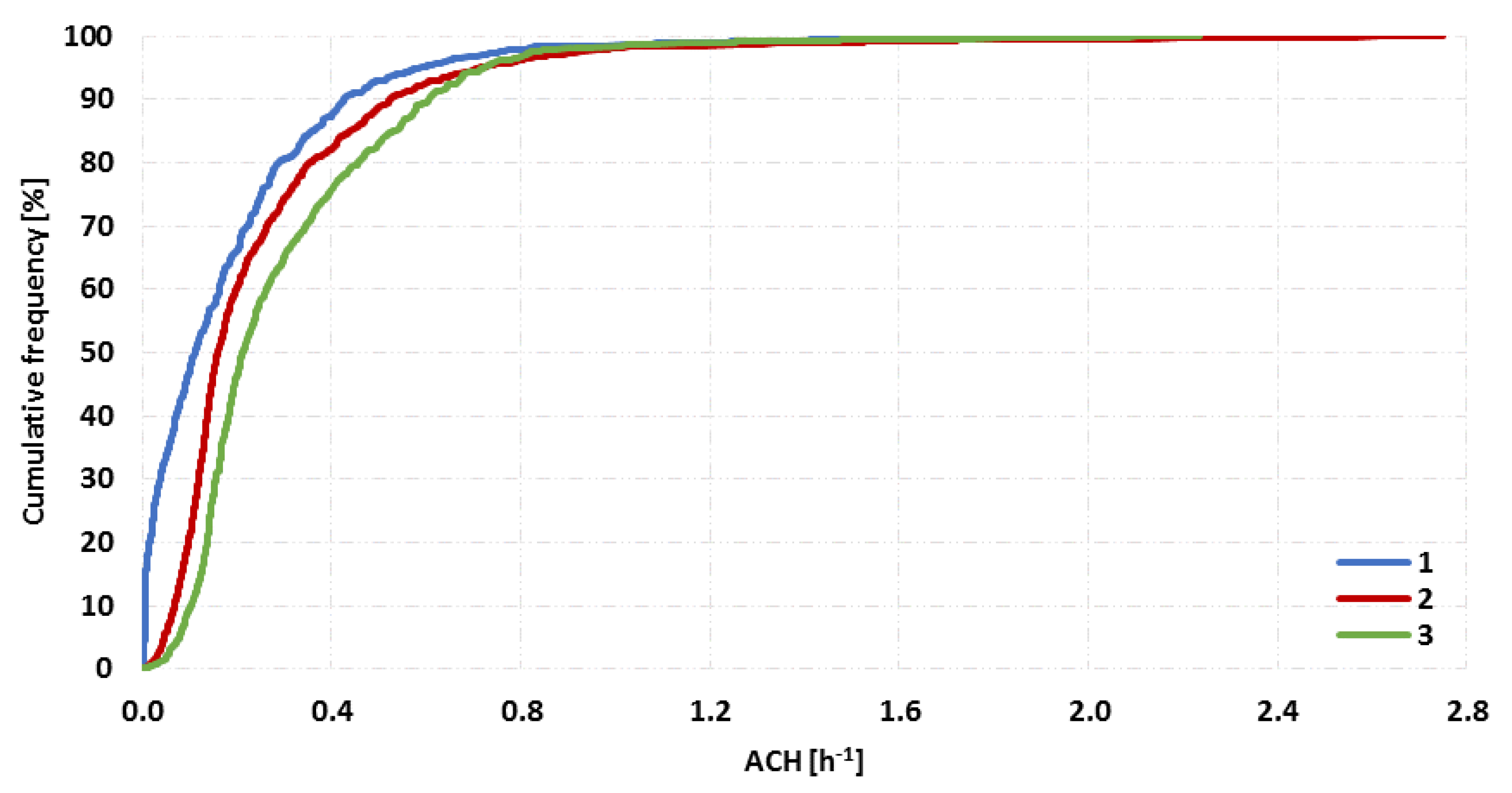
The ELA50 calculated from the results of the blower door test was 206.99 cm2. After conversion to ELA4, it totals 141.71 cm2. Figure 5 portrays the evolution and distribution of the ACH in each of the three modeled scenarios, considering MEV off and hence natural ventilation conditions. The ACH only exceeds 1.2 h−1 in three instances and for very short periods. The ACH suffers significant variations during the simulated period in all three scenarios, as peak values occur often. The boxplot representation evidence the increasing trend for higher ACH values as leakage air paths adopt a more disperse configuration (Scenario 3).
The average (µ), the standard deviation (σ), the maximum (M), and the interquartile range (IQR), for each scenario, can be consulted in Table 8. Averagely, there is an ACH increase from Scenario 1 to Scenario 2 of 38.0%, and from Scenario 1 to Scenario 3 of 62.6%. Still, the highest variation in ACH and the maximum resulting values do not occur in Scenario 3. Despite having the wider IQR, it presents the lowest maximum ACH. Scenario 2 shows the highest maximum ACH and the highest variance. Figure 6 illustrates these trends.
As the configuration of air leakage paths get progressively more disperse, the sweeping effect of air movement from bedroom to bathroom gets reduced. In Scenario 1, 23.6% of the infiltrating air through the bedroom gets exfiltrated through the bathroom. In Scenario 2 and 3, this value is reduced to 13.7% and 9.5%, respectively. The value found in Scenario 1 is in agreement with the results of the tracer gas measurements which indicated that 24.2% of the infiltrating air through the bedroom is extracted through the bathroom.

4.3. Step II: Effect of Airtightness Levels

In the second step of the research, four levels of airtightness were applied in the three scenarios. This variation allowed assessing the impact of airtightness levels on the air change rates, with and without the mechanical extraction activated in the bathroom. As airtightness levels change, the total ELA considered for simulation was also modified. For the four levels of airtightness, Table 9 presents the resulting ELA4 after airflow volume transformation and conversion to 4 Pa of pressure difference.
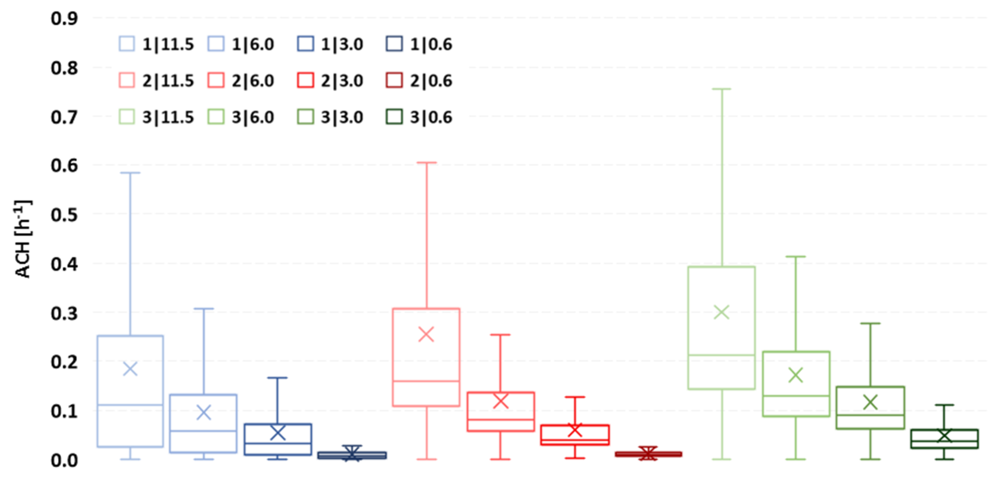
For the cases with MEV off, as expected, all scenarios show a significant reduction in the resulting ACH as airtightness increases (Figure 7). For visualization purposes, outliers were not included in the figure.
Average ACH values fall in a higher proportion in Scenario 3 than in any other. When airtightness level increases in that scenario, the average ACH drops by 57, 68 and 41%. For Scenario 1, the average decreases by 52, 56 and 18%, and in Scenario 2 it decreases by 47, 50 and 20%.
As the envelope gets increasingly airtight, the ACH distribution experiences ever fewer disturbances for all the air leaks configurations considered. The behavior of the three less airtight levels (11.5/6.0/3.0 h−1) show a similar evolution regarding the proportionality on ACH distribution between configurations. When the envelope is very airtight (0.6 h−1), the most disperse configuration of air leakage paths, Scenario 3, shows a less significant relative contraction on the ACH distribution, compared to the others.
Scenario 2 is the one showing a more significant concentration of values from one airtightness level to the next. It may indicate the higher impact of increasing airtightness levels on the stack effect contribution for ACH, as this is the scenario that puts the most relative importance in floor/wall and wall/ceiling joints, maximizing the effect of the indoor height.
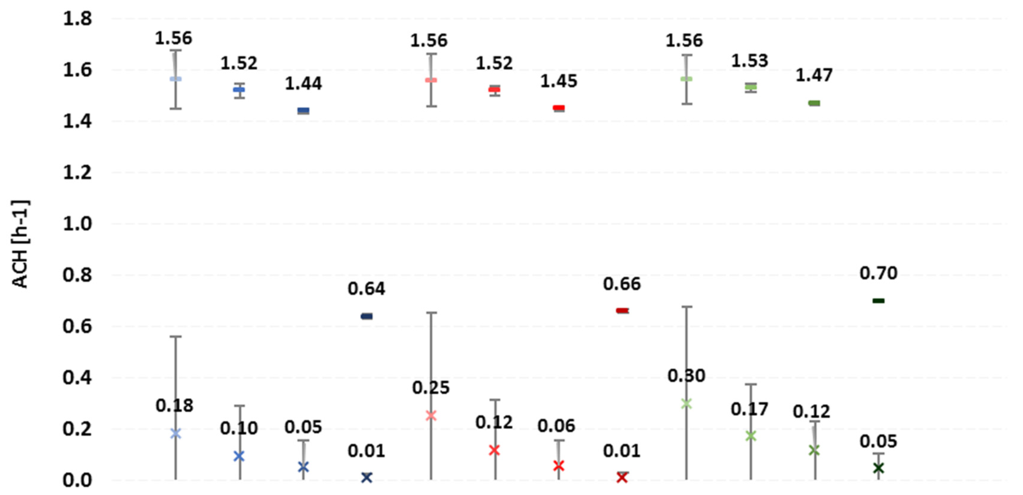
Figure 8 shows the ACH averages and standard deviations for the different simulated cases. For the cases with MEV on, as supposed, the values of ACH experience less disperse distributions in comparison with the cases without MEV. As the envelope becomes more airtight, so the ACH distribution deviates less from its average, confirming that mechanical ventilation provides more consistent ACH when paired with tighter envelopes.
For these modeled cases, with MEV on, the effect of changing air leakage path configurations can be considered negligible, since, for all of them, the average ACH evolution is practically the same as the airtightness level increases. This result reinforces the need to assess airtightness performance when designing HVAC systems. For distinct levels of airtightness, ventilation elements, when active, will induce specific ranges of pressure differentials on building envelopes. As ventilation equipment operates at different airflow volumes with dissimilar pressure differentials, the resulting ACH average and range will vary.
In all scenarios, there is a significant reduction of the average ACH from an ACH50 of 3.0 to 0.6 h−1. This occurs since when MEV is on the ACH is driven by the performance curve of the extractor in the bathroom, that is, by the relation between the induced pressure differential on the envelope and the volume of extracted air. For the case of Scenario 2 with and ACH50 of 3.0 h−1, the average pressure differential of the air leakage paths is 17.3 Pa, and the bedroom–bathroom sweeping effect is apparent, as can be seen in Figure 9. The contribution of infiltration through the bedroom totals 86.7% of the 89.5 m3h−1 exhausted through the bathroom extractor.

5. Conclusions

Most Southern European countries do not have specific regulations for building airtightness. Nevertheless, there is a trend of increasing airtightness that may lead to insufficient ventilation in dwellings if an adequate ventilation system is not adopted. The case study analyzed in this study represents a common Portuguese situation with highly permeable envelopes. Several conclusions can be drawn:
  • This type of dwelling usually presents a low average air change rate associated with highly variable hourly values. The tracer gas measurements carried out in the case study allowed us to conclude that most of the air that infiltrates through the bedroom also exfiltrates in it. A bedroom–bathroom sweeping effect only occurred when MEV was on.
  • Although there are limitations on the comparison of real data with simulation results, as there is uncertainty in measurements and discretization in the input data, significant accord between estimate values of ACH on measurement results and one of the scenarios is found. Scenario 1 (1.56 h−1), corresponding to air leaks concentrated in fewer locations, showed significant agreement with the obtained in-situ results (1.52 h−1). With MEV off, the simulation output 0.19 h−1, and CO2 measurements resulted in 0.15 h−1.
  • The distribution of the ELA through different leakage path configurations is an impactful factor when addressing ACH. From the most concentrated air leakage path configuration to the most disperse one, Scenario 1–3, there is an increase of around 63% of the ACH.
  • The adequate design of mechanical ventilation systems depends on prior knowledge of the airtightness level, as the whole system performance depends on it. In this particular case study, the simulation shows, for the most penalizing difference, ACH50 change from 11.5 to 0.6 h−1; in Scenario 1, the ACH drops 0.92 h−1.
The results of the current analysis confirmed that the relation between airtightness and air change rates should be carefully analyzed in southern European countries. Indoor air quality, comfort of occupants, and energy efficiency of buildings are highly influenced by the configuration of air leakage paths and airtightness levels.
The identification and sealing of air leakage paths, and further testing in the case study, would give additional data for input and comparison with simulation results. Although not being in the aims of the present study, it would be an interesting methodology to develop and apply in the future. Together with the consideration of uncertainties, in the case of sensitivity analysis, the methodology applied in this research can be generalized to increasingly complex and comprehensive case studies.

Author Contributions

Conceptualization, N.M.M.R. and R.M.S.F.A.; methodology, V.E.M.C., N.M.M.R. and R.M.S.F.A.; investigation, V.E.M.C and P.F.P.; formal analysis, V.E.M.C and P.F.P.; writing—original draft preparation, V.E.M.C and P.F.P.; writing—review and editing, N.M.M.R. and R.M.S.F.A. All authors have read and agreed to the published version of the manuscript.

Funding

This work was financially supported by: Base Funding—UIDB/04708/2020 and Programmatic Funding—UIDP/04708/2020 of the CONSTRUCT—Instituto de I&D em Estruturas e Construções—funded by national funds through the FCT/MCTES (PIDDAC). The author would like to acknowledge the support of FCT—Fundacão para a Ciência e a Tecnologia, the funding of the Doctoral Grant PD/BD/135162/2017, through the Doctoral Programme EcoCoRe.

Conflicts of Interest

The authors declare no conflict of interest.

References

  1. European Comission. Heating and Cooling. 2016. Available online: https://ec.europa.eu/energy/en/topics/energy-efficiency/heating-and-cooling (accessed on 7 November 2019).
  2. European Comission. Communication from the Commission to the European Parliament, the Council, the European Economic and Social Committee and the Committee of the Regions on an EU Strategy for Heating and Cooling PART 1/2 {COM(2016) 51 Final}; European Comission: Brussels, Belgium, 2016. [Google Scholar]
  3. Carlos, J.S.; Silva, P.D.; Corvacho, H.; Gomes, J.P.C. Pré-aquecimento do ar de Ventilação: Recomendações para estratégias bioclimáticas. Eng. Civ. 2010, 38, 45–56. [Google Scholar]
  4. Liddament, M.W.; Orme, M. Energy and ventilation. Appl. Therm. Eng. 1998, 18, 1101–1109. [Google Scholar] [CrossRef]
  5. European Comission. Directive 2010/31/EU of the European Parliament and of the Council of 19 May 2010 on the energy performance of buildings. Off. J. Eur. Union 2010, 153, 13–35. [Google Scholar]
  6. Bomberg, M.; Kisilewicz, T.; Nowak, K. Is there an optimum range of airtightness for a building? J. Build. Phys. 2015, 39, 395–421. [Google Scholar] [CrossRef]
  7. Awbi, H.B. Ventilation Systems: Design and Performance; Routledge: New York, NY, USA, 2008. [Google Scholar]
  8. Linden, P.F. The Fluid Mechanics of Natural Ventilation. Annu. Rev. Fluid Mech. 1999, 31, 201–238. [Google Scholar] [CrossRef] [Green Version]
  9. Awbi, H.B. Ventilation of Buildings, 2nd ed.; Taylor & Francis: Philadelphia, PA, USA, 2003. [Google Scholar]
  10. ASHRAE. Chapter 16: Ventilation and infiltration. In ASHRAE Handbook Fundamental; ASHRAE: Atlanta, GA, USA, 2013; pp. 16.1–16.37. [Google Scholar]
  11. Wilson, A.G.; Tamura, G.T. Stack effect in buildings. In Canadian Building Digest; no. CBD-104; National Research Council Canada, Division of Building Research: Ottawa, QC, Canada, 1968. [Google Scholar]
  12. ASHRAE. Chapter 24: Airflow around buildings. In ASHRAE Handbook Fundamental; ASHRAE: Atlanta, GA, USA, 2013; pp. 24.1–24.15. [Google Scholar]
  13. Concannon, P. Technical Note AIVC 57 Residential Ventilation; AIVC: Brussels, Belgium, 2002. [Google Scholar]
  14. Sinden, F.W. Wind, temperature and natural ventilation—Theoretical considerations. Energy Build. 1978, 1, 275–280. [Google Scholar] [CrossRef]
  15. Walker, I.S.; Wilson, D.J. Evaluating models for superposition of wind and stack effect in air infiltration. Build. Environ. 1993, 28, 201–210. [Google Scholar] [CrossRef]
  16. Liddament, M.W. A Guide to Energy Efficient Ventilation; Air Infiltration Vent. Center, (AIVC): Brussels, Belgium, 1996. [Google Scholar]
  17. Guyot, G.; Carrié, R.; Schild, P. Stimulation of good building and ductwork airtightness through EPBD. ASIEPI Intell. Energy Eur. 2010, 2, 3. [Google Scholar]
  18. Sherman, M.H.; Chan, R. Building Airtightness: Research and Practice. In Building Ventilation; Routledge: New York, NY, USA, 2004; pp. 1–46. [Google Scholar]
  19. Guyot, G.; Sherman, M.H.; Walker, I.S. Smart ventilation energy and indoor air quality performance in residential buildings: A review. Energy Build. 2018, 165, 416–430. [Google Scholar] [CrossRef] [Green Version]
  20. Limb, M.J. TN55—A Review of International Ventilation, Airtightness, Thermal Insulation and Indoor Air Quality Criteria. Tech. Note AIVC 2001, 55, 203. [Google Scholar]
  21. Retrotec Inc. Airtightness Requirements; Retrotec Inc.: Everson, WA, USA, 2014; Available online: https://retrotec.com/pub/media/mageworx/downloads/attachment/file/a/r/article-_airtightness_requirements.pdf (accessed on 13 February 2018).
  22. Meiss, A.; Feijó-Muñoz, J. The energy impact of infiltration: A study on buildings located in north central Spain. Energy Effic. 2015, 8, 51–64. [Google Scholar] [CrossRef]
  23. ISO. EN ISO 9972: 2015 Thermal Performance of Buildings—Determination of Air Permeability of Buildings—Fan Pressurization Method; ISO: Geneva, Switzerland, 2015. [Google Scholar]
  24. Baker, P.H.; Sharples, S.; Ward, I.C. Air flow through cracks. Build. Environ. 1987, 22, 293–304. [Google Scholar] [CrossRef]
  25. Liddament, M.W. Power law rules—OK? Air Infiltration Rev. 1987, 8, 4–6. [Google Scholar]
  26. Kronvall, J.; Persily, A.K. Personal Communication; Princeton University: Princeton, NJ, USA, 1984. [Google Scholar]
  27. ASTM. ASTM E741—11(2017) Standard Test Method for Determining Air Change in a Single Zone by Means of a Tracer Gas Dilution; ASTM: West Conshohocken, PA, USA, 2017. [Google Scholar]
  28. Chao, C.Y.; Wan, M.P.; Law, A.K. Ventilation performance measurement using constant concentration dosing strategy. Build. Environ. 2004, 39, 1277–1288. [Google Scholar] [CrossRef]
  29. Νikolopoulos, N.; Νikolopoulos, A.; Larsen, T.S.; Nikas, K.-S.P. Experimental and numerical investigation of the tracer gas methodology in the case of a naturally cross-ventilated building. Build. Environ. 2012, 56, 379–388. [Google Scholar] [CrossRef]
  30. Cui, S.; Cohen, M.; Stabat, P.; Marchio, D. CO2 tracer gas concentration decay method for measuring air change rate. Build. Environ. 2015, 84, 162–169. [Google Scholar] [CrossRef]
  31. Coley, D.A.; Beisteiner, A. Carbon Dioxide Levels and Ventilation Rates in Schools. Int. J. Vent. 2002, 1, 45–52. [Google Scholar] [CrossRef]
  32. Orme, M. Applicable Models for Air Infiltration and Ventilation Calculations. AIVC Tech. Note 1999, 51, 1–66. [Google Scholar]
  33. Liddament, M.W. Air Infiltration Calculation Techniques—An Application Guide; Air Infiltration and Ventilation Centre: Berkshire, UK, 1986. [Google Scholar]
  34. Kronvall, J. Correlating pressurization and infiltration rate data-tests of an heuristic model; Lund Institute of Technology, Division of Building Technology: Lund, Sweden, 1980; pp. 225–243. [Google Scholar]
  35. Chan, W.R.; Joh, J.; Sherman, M.H. Analysis of air leakage measurements of US houses. Energy Build. 2013, 66, 616–625. [Google Scholar] [CrossRef]
  36. Orme, M.; Leksmono, N. Ventilation modelling data guide. AIVC Guide 2002, 5, 80. [Google Scholar]
  37. Walker, I.; Wilson, D. AIM 2: The Alberta Air Infiltration Model; University of Alberta: Edmonton, Alberta, 1990. [Google Scholar]
  38. Feustel, H.E. COMIS—An international multizone air-flow and contaminant transport model. Energy Build. 1999, 30, 3–18. [Google Scholar] [CrossRef] [Green Version]
  39. Tan, G.; Glicksman, L.R. Application of integrating multi-zone model with CFD simulation to natural ventilation prediction. Energy Build. 2005, 37, 1049–1057. [Google Scholar] [CrossRef]
  40. Younes, C.; Shdid, C.A. A methodology for 3-D multiphysics CFD simulation of air leakage in building envelopes. Energy Build. 2013, 65, 146–158. [Google Scholar] [CrossRef]
  41. Hayati, A.; Mattsson, M.; Sandberg, M. Evaluation of the LBL and AIM-2 air infiltration models on large single zones: Three historical churches. Build. Environ. 2014, 81, 365–379. [Google Scholar] [CrossRef]
  42. Persily, A.K.; Linteris, G.T. A comparison of measured and predicted infiltration rates. ASHRAE Trans. 1983, 89, 183–197. [Google Scholar]
  43. Allegrini, J.; Carmeliet, J. Simulations of local heat islands in Zürich with coupled CFD and building energy models. Urban Clim. 2018, 24, 340–359. [Google Scholar] [CrossRef]
  44. Richardson, G.M.; Robertson, A.P.; Hoxey, R.P.; Surry, D. Full-scale and model investigations of pressures on an industrial/agricultural building. J. Wind Eng. Ind. Aerodyn. 1990, 36, 1053–1062. [Google Scholar] [CrossRef]
  45. Orme, M.; Liddament, M.; Wilson, A. Numerical Data for Air Infiltration and Natural Ventilation Calculations; Air Infiltration and Ventilation Centre: Bracknell, UK, 1998. [Google Scholar]
  46. Grosso, M. Wind pressure distribution around buildings: A parametrical model. Energy Build. 1992, 18, 101–131. [Google Scholar] [CrossRef]
  47. Cóstola, D.; Blocken, B.; Ohba, M.; Hensen, J.L.M. Uncertainty in airflow rate calculations due to the use of surface-averaged pressure coefficients. Energy Build. 2010, 42, 881–888. [Google Scholar] [CrossRef] [Green Version]
  48. ASTM. ASTM D6245—18 Standard Guide for Using Indoor Carbon Dioxide Concentrations to Evaluate Indoor Air Quality and Ventilation; ASTM: West Conshohocken, PA, USA, 2018. [Google Scholar]
  49. Bekö, G.; Gustavsen, S.; Frederiksen, M.; Bergsøe, N.C.; Kolarik, B.; Gunnarsen, L.; Clausen, G. Diurnal and seasonal variation in air exchange rates and interzonal airflows measured by active and passive tracer gas in homes. Build. Environ. 2016, 104, 178–187. [Google Scholar] [CrossRef] [Green Version]
  50. Bekö, G.; Lund, T.; Nors, F.; Toftum, J.; Clausen, G. Ventilation rates in the bedrooms of 500 Danish children. Build. Environ. 2010, 45, 2289–2295. [Google Scholar] [CrossRef]
  51. Retrotec Inc. Spec-Blower Door 1000; Retrotec Inc.: Everson, WA, USA, 2012; Available online: https://assets.tequipment.net/assets/1/26/Spec-Blower_Door_1000-SP110.pdf (accessed on 16 May 2019).
  52. Retrotec Inc. Gauge Specifications for DM-2; Retrotec Inc.: Everson, WA, USA, 2010. [Google Scholar]
  53. CEN. Thermal Performance of Buildings—Determination of Air Permeability of Buildings—Fan Pressurization Method, EN 13829-2000; Comite Europeen de Normalisation: Brussels, Belgium, 2000. [Google Scholar]
  54. Weather Data Sources. 2019. Available online: https://energyplus.net/weather/sources#INETI (accessed on 14 November 2019).
  55. Persily, A.K.; Ivy, E.M. Input data for multizone airflow and IAQ analysis. In NIST Interagency/Internal Report (NISTIR)-6585; NIST: Gaithersburg, MD, USA, 2001; Available online: https://www.nist.gov/el/energy-and-environment-division-73200/nist-multizone-modeling/software-tools/contam/libraries (accessed on 14 November 2019).
  56. Swami, M.V.; Chandra, S. Correlations for pressure distribution on buildings and calculation of natural-ventilation airflow. ASHRAE Trans. 1988, 1, 243–266. [Google Scholar]
  57. Dols, W.S.; Polidoro, B.J. NIST Technical Note 1887 CONTAM User Guide and Program Documentation. 2007. Available online: https://nvlpubs.nist.gov/nistpubs/TechnicalNotes/NIST.TN.1887.pdf (accessed on 15 November 2019).
  58. Persily, A.K. A Modeling Study of Ventilation, Iaq and Energy Impacts of Residential Mechanical Ventilation; NIST: Gaithersburg, MD, USA, 1998. [Google Scholar]
  59. Wang, L.; Dols, W.; Chen, Q. Using CFD Capabilities of CONTAM 3.0 for Simulating Airflow and Contaminant Transport in and around Buildings. Hvac&R Res. 2010, 16, 749–763. [Google Scholar]
  60. Dequaire, X. Passivhaus as a low-energy building standard: Contribution to a typology. Energy Effic. 2012, 5, 377–391. [Google Scholar] [CrossRef]
  61. Weidt, J.L.; Weidt, J.; Selkowitz, S.E. Field Air Leakage of Newly Installed Residential Windows. ASHRAE Trans. 1979, 85, 149–159. [Google Scholar]
  62. ASHRAE. 2001 ASHRAE Handbook: Fundamentals; ASHRAE: Atlanta, GA, USA, 2001. [Google Scholar]
  63. Sherman, M.H.; Grimsrud, D.T. Measurement of infiltration using fan pressurization and weather data. NASA STI/Recon Technical Report N. In Proceedings the First Air Infiltration Centre Conference, Windsor, UK, 6–8 October 1980; Volume 81. [Google Scholar]
  64. Ramos, N.M.M.; Almeida, R.M.S.F.; Curado, A.; Pereira, P.F.; Manuel, S.; Maia, J. Airtightness and ventilation in a mild climate country rehabilitated social housing buildings—What users want and what they get. Build. Environ. 2015, 92, 97–110. [Google Scholar] [CrossRef]
  65. Sherman, M.H. Infiltration-Pressurization Correlation: Simplified Physical Modeling. 1980. Available online: https://escholarship.org/uc/item/8wd4n2f7 (accessed on 6 November 2019).
Figure 1. Studied compartments.
Buildings 10 00055 g001
Figure 2. Plan considered for simulation.
Buildings 10 00055 g002
Figure 3. Representation of the CONTAM model of the most comprehensive scenario (Scenario 3) with mechanical extraction ventilation (MEV) added. For leakage type code, refer to Table 5. For additional characteristics on the air leakage paths and respective weight on the total ELA, refer to Table 6.
Buildings 10 00055 g003
Figure 4. Hourly averaged climatic data [54]: (a) exterior air temperature; (b) wind speed and direction frequency.
Buildings 10 00055 g004
Figure 5. Hourly averaged ACH for the simulated period and boxplot representation in the three modeled scenarios with natural ventilation conditions; scenarios—1 (blue), 2 (red), 3 (green).
Buildings 10 00055 g005
Figure 6. Cumulative frequencies of ACH for the modeled scenarios on air leakage paths configuration; scenarios—1 (blue), 2 (red), 3 (green).
Buildings 10 00055 g006
Figure 7. ACH distribution in the different configurations of air leakage paths for the four airtightness levels considered (Scenario|ACH50 (h−1)); scenarios—1 (blue), 2 (red), 3 (green).
Buildings 10 00055 g007
Figure 8. Average (labels) and standard deviation of ACH values: MEV on (dash)–MEV off (cross); scenarios—1 (blue), 2 (red), 3 (green); lighter to darker colour grade with increasing airtightness levels.
Buildings 10 00055 g008
Figure 9. CONTAM simulation results for Scenario 2 assuming an ACH50 of 3.0 h−1: relative quantities of airflow volumes and direction (green bars); relative pressure differentials and pressurization mode (red bars).
Buildings 10 00055 g009
Table 1. Relationship between ventilation strategies and ACH50 [16]
ACH50Ventilation Strategy
ACH50 > 8 h−1Adventitious ventilation
4 h−1 < ACH50 < 8 h−1Natural ventilation
1 h−1 < ACH50 < 5 h−1Mechanical extraction ventilation
ACH50 < 1 h−1Balanced ventilation with heat recovery
Table 2. Airtightness requirements/recommendations in several European countries normalized to ACH50 (when needed) [21,22].
CountryCondition VariableRequirements/Recommendations
AustriaNatural ventilation3.0
Czech RepublicNatural ventilation4.5
Forced1.5
Forced + heat recovery1.0
DenmarkResidential6.5
EstoniaNew7.2
Existing10.8
FinlandBuilding heat loss reference2.0
Energy Performance Certificate4.0
FranceSingle-family houses4.3
Other residential buildings6.5
GermanyMechanical ventilation1.5
Natural ventilation3.0
LithuaniaNatural ventilation3.0
Mechanical ventilation1.5
LatviaResidential3.0
NetherlandsMechanical ventilation2.0–3.0
Natural ventilation4.0–6.0
NorwayResidential3.0
SloveniaNatural ventilation3.0
Mechanical ventilation2.0
SlovakiaResidential2.0–4.0
SpainRatio between volume and floor area3.0–6.0
United KingdomBest practice natural ventilation6.0
Best practice mechanical ventilation1.2
Normal practice natural ventilation8.4
Normal practice mechanical ventilation6.0
Cyprus, Greece, Italy, Malta, Portugal-no requirements
Table 3. Characteristics of the two compartments.
CompartmentType of WindowFloor AreaVolume
BedroomWindows frame double slide18.346.9
BathroomSingle windows frame
Side hung
5.012.8
Table 4. Specifications of the equipment used in the experimental campaign.
EquipmentAccuracyRangeResolutionDelay
CO2 NDIR sensor±25 ppm or ±3% (0–2000 ppm)
±30 ppm or ±3% (2000–5000 ppm)
0 to 5000 ppm1 ppm3 min to 90% of accuracy
Table 5. Equated types of air leakage paths and their considered normalized ELA ( ELA r , n ) based on best estimate values [55].
ScenarioCode-Type of Air Leak E L A r , n
123A—Windows, double horizontal slider, aluminum, weather-stripped0.72 cm2/m
B—Windows, casement with weather-stripping0.24 cm2/m
23C—Joints, sole plate, floor/wall, caulked0.8 cm2/m
D—Joints, ceiling wall1.5 cm2/m
3E—Electrical outlets/switches, no gaskets2.5 cm2/item
F—Piping/Plumbing/Wiring penetrations, caulked2.0 cm2/item
Table 6. Air leakage type, metric, extension, envelope orientation, and relative importance in ELA percentage of the modeled scenarios. Relative elevation refers to mid-height of the air leakage path to floor level.
Air Leakage Path TypeInterface MetricInterface ExtensionRelative Elevation [m]Envelope OrientationScenario ELA %
BedroomBathroom123
Am8.8 1.0South30.015.29.5
8.8 1.0South30.015.29.5
10.7 1.0East36.618.411.5
B 3.01.3East3.41.71.1
C4.0 0.0South 7.74.8
2.9 0.0East 5.63.5
2.10.0East 4.02.5
D4.0 2.56South 14.39.0
2.9 2.56East 10.46.5
2.12.56East 7.54.7
E1/E2item2/2 0.3/1.1South 14.9
1/1 0.3/1.1East 7.5
F 55 × 0.5East 15.0
Table 7. Average ACH and ACH50 results.
CompartmentMEV on ACH [h−1]MEV off ACH [h−1]ACH50 [h−1]
Bedroom0.78 0.15-
Bathroom4.210.13-
Total1.520.1511.50
Table 8. Statistical data on the ACH each of the three modeled scenarios.
ACH [h−1]Scenario
123
µ0.1850.2540.301
σ0.2390.2750.243
M2.2462.7482.235
IQR0.2260.1980.248
Table 9. Airflow data transformation and conversion for the four airtightness levels.
ACH50 [h−1]Q50 [m3h−1]ELA50 [cm2]ELA4 [cm2]
11.5687.1209.1143.2
6.0358.2109.074.6
3.0179.154.537.3
0.635.810.97.5