1. Introduction
Cross-Laminated Timber (CLT) is a high-efficient engineered wood product widely developed in the last two decades all over the world. Due to its prerogatives of a high strength, stiffness, and material sustainability, this product is particularly suitable to be used to build new CLT buildings or as a retrofitting solution in existing buildings [
1,
2,
3,
4].
CLT panels consist of alternate glued layers of boards, one which the other rotated around at a right angle. This lay-up orientation allows CLT panels to work either as a membrane or as a plate and then used as a wall or floor element alternatively.
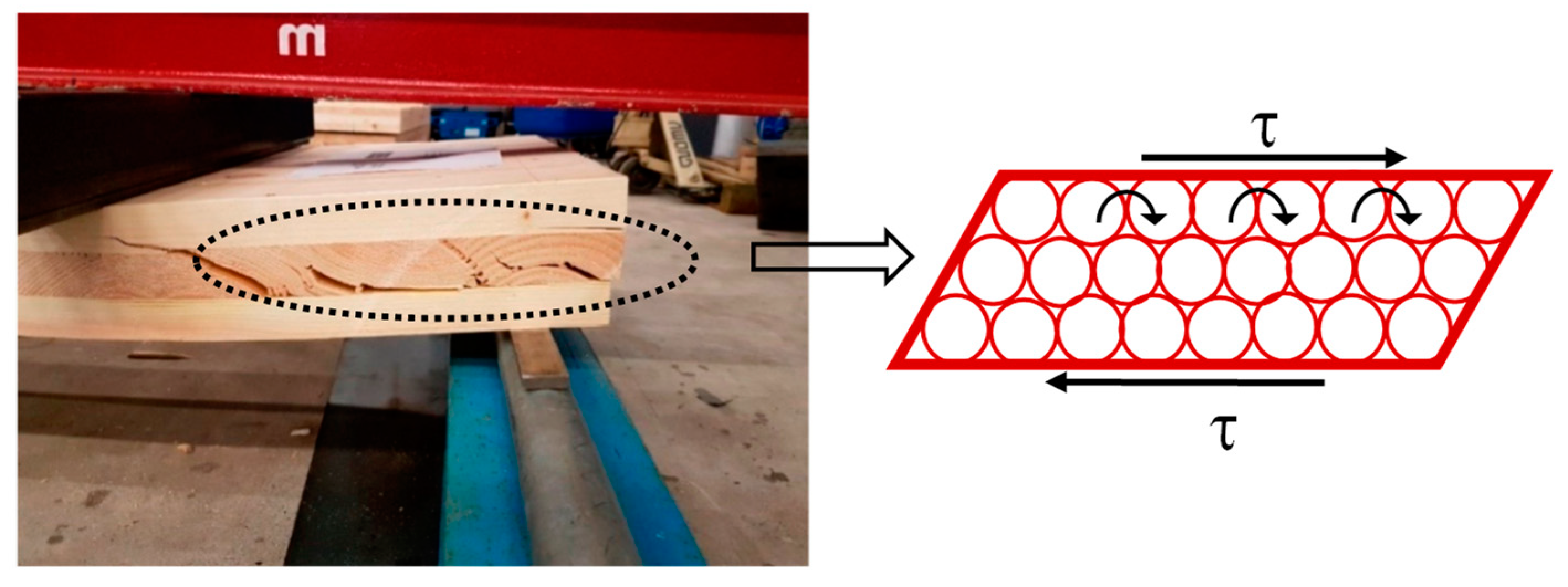
The Euler–Bernoulli’s hypothesis concerning the conservation of plain transversal cross-sections after the deformation of the structural element is not useable in the case of CLT panels subjected to out-plane bending. In fact, the low value of the shear modulus in orthogonal to grain direction (i.e., rolling shear modulus—G
R) involves significant shear deformations in the layers that are orthogonally oriented with respect to the direction of the tangential stresses (here named transverse layers) (
Figure 1). As a result, out-of-plane deflections and vibrations increase in CLT floors under service conditions, producing discomfort for the users. Low values of perpendicular-to-grain shear strength have been measured by experimental tests; then, the rolling shear failure mode in the transverse layers has been frequently observed [
5,
6]. In Eurocode 5 [
7], a characteristic value of rolling shear strength equal to 1.0 MPa is a reliable value suggested for wood, independently from its species and class strength.
The rolling shear phenomenon is still a problem under study by experimental, analytical, and numerical point of view. Fellmoser and Blass [
6] carried out one of the first studies on this topic, investigating the effect of rolling shear modulus on the flexural behavior of CLT floors characterized by different length-to-depth (L/H) aspect ratios.
The influence of shear deformations on the cross-layer has also been examined with three-point bending tests in Mastek et al. [
8] and in Minghao Li [
9]. Recently, experimental tests and numerical models have also been presented in Franzoni et al. [
10], in which the influence of large and small gaps between lateral boards (lamellas) on mechanical behavior of CLT panels subjected to vertical loads with respect to its mid-plane has been highlighted, while experimental measurements of rolling shear properties on soft and hardwood species were carried out by Zhou et al. [
11] and O’ Ceallaigh et al. [
5]. An extensive experimental campaign (consisting of 342 tests), aimed to evaluate the rolling shear properties of six timber species, with three different sawing patterns and three different aspect ratios of specimens, has been conducted by Ehahart and Brandner [
12].
Saavedra Flores et al. [
13] presented a numerical study regarding the multi-scale modelling of rolling shear failure mode in CLT panels, while Sturzenbecher et al. [
14] investigated the structural design and modeling by advances plates theory.
In order to provide a practical tool for engineering applications, analytical methods for evaluating the flexural and shear stiffness, the stress state, and the deflections in CLT panels loaded out-of-plane have been developed in these years. Some of these methods, properly developed for cross-layered panels, take into account the rolling shear deformation in transverse layers and have been also included in specific standards, guidelines, or handbooks [
7,
15,
16].
Considering that not at all correct results are given by Euler-Bernoulli’s beam theory for shear-dominated structural elements, specific methods such as Shear Analogy Method (SAM) [
17] and Timoshenko theory were developed. The latter two methods are based on a more accurate theory, but a greater computational effort is required for their applications. A comparison between Timoshenko theory and SAM with respect to the experimental results obtained on 3- and 5-layer CLT panels is reported in Niederwestberg et al. [
18]. Alternatively, a modification of γ-method—included in the current version of Eurocode 5 for calculating composite timber beams—has been proposed as suitable for accounting the rolling shear effect in CLT floor elements [
19].
This paper presents a study on the influence of rolling shear deformation on the out-of-plane flexural behavior of CLT panels at service limit states (SLS). The most of existing literature papers mainly deal with experimental results on rolling shear modulus measurement, development of analytical methods, or mathematical modelling by advanced plate theory. At date, specific information which could become useful suggestions for the technical codes for constructions are still missing. In the light of this, the present paper investigates the role of rolling shear deformation by a more practical point of view and contributes to cover the gap existing between pure theoretical investigations and concrete applications.
The paper takes inspiration from the work presented on 2004 by Fellmoser and Blass [
6], in which the influence of the rolling shear effect on the out-of-plane deflections of cross-layered panels was firstly highlighted, even if indications on the stress state have not been provided. In order to quantify the incidence of rolling shear on floors deflections, several aspects have been better deepened while others properly investigated in this paper, such as: (
i) the effect of the span-to-length ratios (L/H) ratios on both instantaneous and global deflections at SLS, for a large range of L/H typically used in real buildings; and (
ii) the modification of the stress state within the panel due to rolling shear.
These aspects have also been studied applying the analytical methods commonly used in literature for taking into account the rolling shear problem and comparing the results provided by them. This gave the possibility of comparing and verifying the effectiveness of the different methods and computing the weight given to the rolling shear by each method. This has allowed for quantifying the role of rolling shear in practical application and to define a reasonable range of H/L in which the phenomenon becomes negligible.
Like the above-mentioned, a comparison between the Timoshenko theory and the SAM with respect to the experimental results obtained on 3- and 5-layer CLT panels is reported in Niederwestberg et al. [
18]. An advancement to the results is also provided by the modified γ-method and by a specific 2D numerical model—properly developed by the authors—have been compared in this paper, thus enlarging the field of available results in the scientific literature.
2. Problem Statement
2.1. Rolling Shear Phenomenon
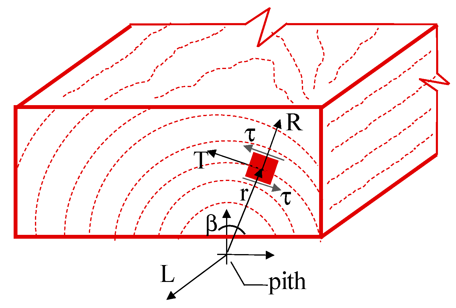
Mechanical behavior and elastic properties of materials with cylindrical anisotropy, such as wood, depend on type and direction of stresses. Nine independent elasticity coefficients are necessary for a complete description of the elastic behavior, usually referred to the three principal anatomic directions: longitudinal (L), tangential (T), and radial (R) (
Figure 2).
Rolling shear is a particular phenomenon that occurs when the tangential stresses (τ) act in the RT-plane orthogonal to the longitudinal axis L (parallel to grain direction), producing the grains rolling off one from each other.
Due to the low value of the elastic tangential modulus in orthogonal to grain direction—named rolling shear modulus G
R—significant shear deformations arise in wooden elements [
6,
8,
9,
10,
11,
12]. There are few structural cases of interest in which this phenomenon could occur, probably the case of the CLT panels working as plates loaded out-of-plane is the most frequent in the structural field. Under this load condition, the transverse layers of boards (i.e., whose grains direction is perpendicular with respect to the plane of bending) are subjected to perpendicular to grain tangential stresses. Shear deformation which arises in these layers could be not negligible and its magnitude growth the maximum deflections (and vibrations), modifying the internal stresses of CLT floors.
Experimental tests performed on macro-scale solid wood specimens devoted to characterize the mechanical shear properties in perpendicular to grains direction have proved that the rolling shear modulus (G
R) cannot be considered an intrinsic property of material: its value not only depends on wood density and annual rings width, but also on the cutting pattern of the boards (i.e., location of pith), size, and geometry of boards cross-section (width-to-thickness of the lamination ratio), as thoroughly highlighted in [
12]. In more detail, for CLT panels, it has been demonstrated that, for decreasing width-to-thickness of the lamination ratios (below to 1.33), the rolling shear decreases disproportionally; consequently, its effect is greater for higher levels of rolling shear moduli [
20].
Despite this, realistic values of the rolling shear modulus commonly suggested for structural size boards cross-section and for a wide wood density range should be larger than 50 MPa, independently from wood species, or at least equal to 1/10 of the elastic tangential modulus (G) in longitudinal direction [
15,
21]. For instance, a mean value G
R=65 MPa and a five-percentile equal to 54 MPa are suggested to be used by the Italian Technical Document CNR DT 206-R1/2018 [
16] for designing glue-laminated timber elements, which also corresponds to 1/10 of the elastic tangential modulus in the longitudinal direction.
As far as the rolling strength is concerned, experimental tests carried out on large scale CLT panels made with three or five layers established a reduced range of characteristic value, from 1.0–2.0 MPa for European spruces, independently from the timber strength class. This topic is beyond the scope of the present paper because the effect of the rolling shear on the deformative flexural behavior of CLT panels is mainly investigated here, whereby additional information can be found in the reference literature works [
5,
12,
14,
16].
2.2. Sectional Behavior of CLT Panels
Due to the transverse layers of boards, the out-of-plane flexural behavior of CLT panels can be assimilated to that of composite beams, in which the transverse layers play the role of ideal fasteners uniformly distributed over the panel length. As is well known, in the composite beams, the shear stiffness of the fasteners affects the amount of both deflections and internal stress state.
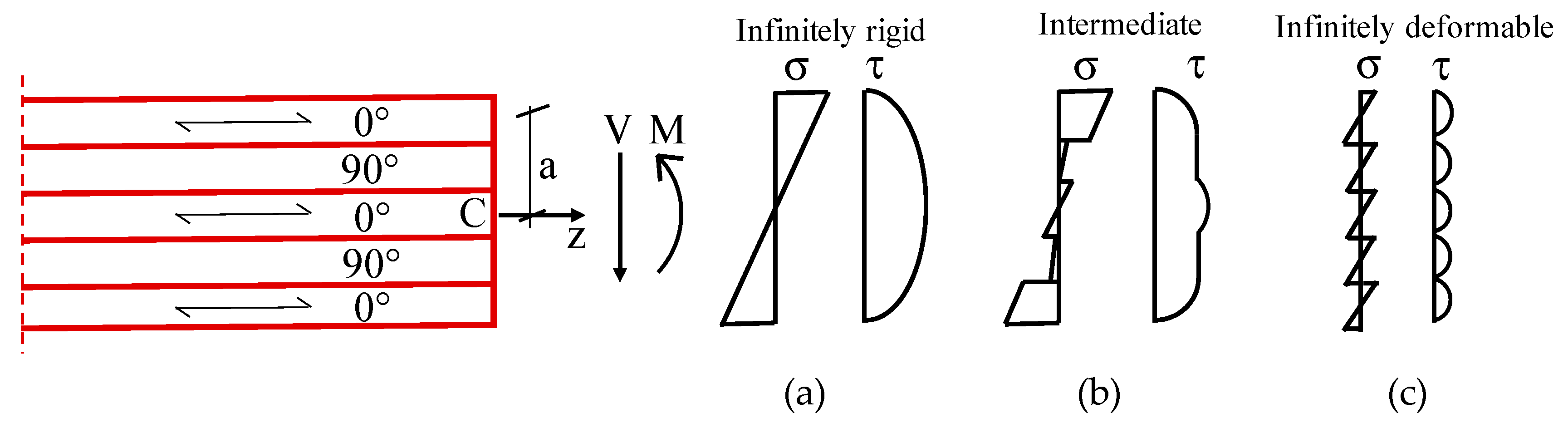
By analogy with composite beams, two limit theoretical behaviors are suitable for CLT panels as a function of shear stiffness of the transverse layers: (i) infinitely rigid connection (named IR in the following); and (ii) infinitely deformable connection. In the case (i), the cross-section behaves as a monolithic without shear sliding between adjacent elements: a bi-triangular distribution of normal stresses (σ) and parabolic for the tangential ones are achieved on the whole cross-section (
Figure 3a). In the case (ii), instead, each layer behaves independently from others due to relative sliding that occurs among the layers of boards: in such a way, a proper diagram of normal and tangential stresses is achieved in each single layer (
Figure 3b).
Between the two limit cases, a very wide range of intermediate behavior is possible in the real applications, depending on shear stiffness of the transverse timber layers. The sectional behavior of typical CLT panels falls exactly into this latter interval: the transverse layers of boards can be idealized as a set of fasteners-type elements, whose shear stiffness depends also on the rolling shear modulus (G
R). In
Figure 3b, the normal and tangential stress distributions obtained in this intermediate case are also schematically represented.
3. Methodology
The Shear Analogy Method (SAM) is an analytical approach properly developed for the out of plane flexural analysis of cross-layered panels, while, for composite beams coupled by mechanical fasteners, the γ-method is mainly used [
7].
In this paper, the modified γ-method has been used to account for the rolling shear effect on CLT, and the results have been compared with those obtained by SAM and numerical analyses. Moreover, the same results have been matched with the limit case in which no sliding in the transverse layers occurs (denoted as ‘IR case’ in
Section 2.2). In other terms, this corresponds to assuming that the longitudinal layers connected by a means of infinitely rigid layers of boards.
In the following
Section 3.1,
Section 3.2 and
Section 3.3, the various methodologies used for calculating the elastic stiffness of CLT panels, accounting for the rolling shear effect, are illustrated. It is important to notice that elastic stiffness has been used in the following to determine both deflections and stresses in CLT panels.
3.1. IR Case
In the case of infinitely rigid transverse layers, the flexural stiffness can be evaluated as follows:
In Equation (1), E represents the Young’s modulus of each timber layer and I the corresponding moment of inertia. Due to the low values of the Young’s modulus in transverse layers (
E90) with respect to those in parallel direction
E0 (
E90 ⋍
E0/30), their contribution has been neglected in the calculations herein performed. Instead,
a is the distance between the center of gravity of the
i-th layer with respect to the center of gravity of the whole cross-section and
A the cross-sectional area of the single layer of the board (
Figure 3).
3.2. Modified γ-Method
The
γ-method represents the most used analytical procedure for composite mono-dimensional beams (i.e., timber-to-timber and timber-to-concrete beams coupled by metal fasteners), whose principal hypotheses are reported in reference books or handbooks on timber topics [
7,
16,
17].
With reference to CLT panels, the modified
γ-method, derived from an adjustment of the basic γ-method presented in EC5 [
7], is also used by engineers in practical applications. The methods rely on Eulero–Bernoulli’s theory, and the shear stiffness is indirectly included in the calculation through an effective flexural stiffness [
19]. In particular, the sliding between adjiacent layers is taken into account through the coefficient
γ, also named the flexibility coeffcient.
The effective flexural stiffness can be evaluated as follows:
In these formulas, the value
E0 has been used for the layers stressed in parallel to the grains direction, while
E90 for the ones stressed in the orthogonal to grains direction. The coefficient
γ is a weighted coefficient depending on both geometrical and mechanical properties of the connection system. It can be evaluated as follows:
where Δz represents the distance between two consecutive fasteners, l the length of the beam, and k the shear stiffness of the connection. In the case of fasteners, k can be evaluated according to the specification included in [
7,
16,
17], whereas, in the case of CLT panels, it has been particularized to evaluate the flexural stiffness of CLT panels, by applying the modifications reported in the following. The stiffness k contained in Equation (3) can be determined, assimilating the transverse layers of the panel to a set of ideal fasteners uniformly distributed over the panel length (
Figure 4). With reference to a finite length Δz of the panel (with cross-section having base B and height H) in its deformed configuration, the shear stiffness of the connections can be written as follows:
The tangential stress is calculated as τ = G
R·α, while the relative displacement between two consecutive layers is
δ =
h·α; the angle α, and the height
h are represented in
Figure 4. Then, by substituting τ and δ in Equation (4), the shear stiffness to used in Equation (3) becomes:
It should be noted firstly that the ‘IR case’ above presented represents a particular case of the γ-method obtained when the flexibility factor is equal to γ = 1.0, and, secondly, that, as the deformability of transverse layers increases, γ tends to zero.
3.3. Shear Analogy Method
This method, originally introduced by Kreuzinger [
17] and now included in [
15], schematizes the panel as an ideal element constituted by two beams (named A and B). Beam A is given by the sum of the inherent flexural and shear stiffness of the individual layer along its own centers, while beam B is given by the Huygens–Stainer points, or an increased moment of inertia because of the distance from the neutral axis of the flexural and shear stiffness of the panel. These beams are coupled with infinitely rigid web elements in order to ensure the same elastic curvature between beams A and B.
The flexural stiffness is evaluated as the sum of those of beam A and beam B:
(
EI)
A and (
EI)
B being the flexural stiffness of beams A and B, respectively, written as follows:
The beam B, instead, provides for the effective shear stiffness evaluated as follows:
3.4. Deflection
Deflections in CLT panels have been calculated according to the beam theory, but taking into account both flexural and shear deformability contributions [
7]. In the case of a simply supported beam subjected to a uniformly distributed load, the maximum deflection is given by:
where
q is the value of the uniformly distributed load,
L the span length of the element, and χ the shear factor that depends on the shape of the transversal cross-section (equal to 1.20 in the case of a rectangular tranversal cross-section). Furthermore, the effective shear stiffness
(GA)eff is evaluted as follows:
where the value of the rolling shear modulus G
R has been considered for the layer stresses in the orthogonal to grains direction, while the shear modulus G for those stressed parallel to the grains direction.
In case of timber elements, the total deflection is given by the sum of the instantaneous (
finst) and the creep (
fcreep) contribution:
The instantaneous part is calculated considering the total load combination at SLS, while the creep contribution is calculated, multiplying the instantaneous part, evaluated for the quasi-permanent load combination [
7], by the coefficient
kdef, which takes into account the service class of the structural element [
7,
16].
4. Case Studies and Finite Element Modelling
A 5-layer CLT panels, with layers thickness t equal to 40 mm, have been considered for the analyses. In
Table 1, the main elastic properties of timber used for calculations are summarized.
Once fixed, the panel height H and different span length (L) variable at a 1-meter of interval (from 1 to 10 meters) have been considered. Thus, a wide range of L/H ratios, varying from 5 to 50, has been considered for the comparative analyses performed in this paper.
A simply supported beam subjected to a uniformly distributed load at an SLS combination has been adopted as a structural scheme. The characteristics’ elementary loads are the following: dead load Gk= 1.76 kN/m2 and live loads Qk = 2.00 kN/m2.
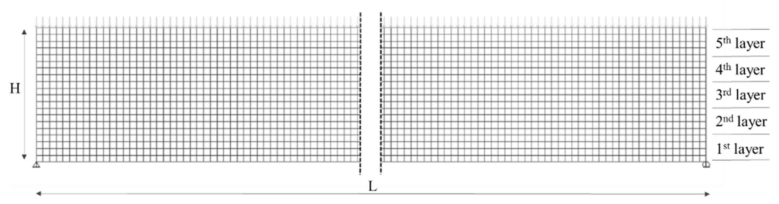
In order to compare the results provided by the analytical methods, numerical models of CLT panels have also been developed using the software package SAP 2000 (Berkeley, USA). 2D finite elements models (FEM) constituted by square-shaped shell elements, with a side dimension equal to 1 cm, were used to model the panels [
1,
4] (
Figure 5). These quadrilateral elements have been linked one each other by means of the function ‘edge constraint’ which connects the joint on the edge to adjacent corner joints of the element.
Due to the arrangement of the CLT layers (orthogonal one to other), the panel behaves as an orthotropic material—the reason why it has been modeled considering its orthotropy by adopting a multi-layer schematization: the elastic moduli in parallel-to-grains direction (
E0 and
G) have been assigned to shell elements of the first, third, and fifth layer, while the orthogonal-to-grains elastic moduli (
E90 and
GR) to the second and fourth layers. The multi layered modeling allows any number of layers to be defined in the thickness direction, each with an independent location, thickness, behavior, and material elastic properties. The multi-layered shell model is based on the elastic plate theory, where, for bending a Mindlin–Reissner formulation, is used, which always includes transverse shear deformation; thus, the rolling shear transverse deformation is taken into account [
10].
The effectiveness of 2D finite element models to schematize the in-plane elastic behavior of CLT panels has been demonstrated for both in-plane [
22,
23] and out-of-plane flexural behavior. In particular, in Franzoni et al. [
10], an FEM model has been adopted to perform numerical analyses on CLT panels subjected to out-of-plane loads and its effectiveness validated with reference to experiental results, while, in Sturzenbecher et al. [
14], the results derived from FEM have been compared with theoretical ones. In Vilguts et al. [
24], finite element schematization has also been assumed to analyze the rolling shear effect on CLT floors. These comparisons have restituted encouraging results and confirmed the validity of the finite element models. Otherwise, the margin of error that may result from this model is limited, as this is an elastic model.
The joints of the quadrilateral shell elements have been selected to apply the nodal actions which simulate the uniformly distributed load; this is because the used software allows for applying forces in the nodal intersections between shell elements only.
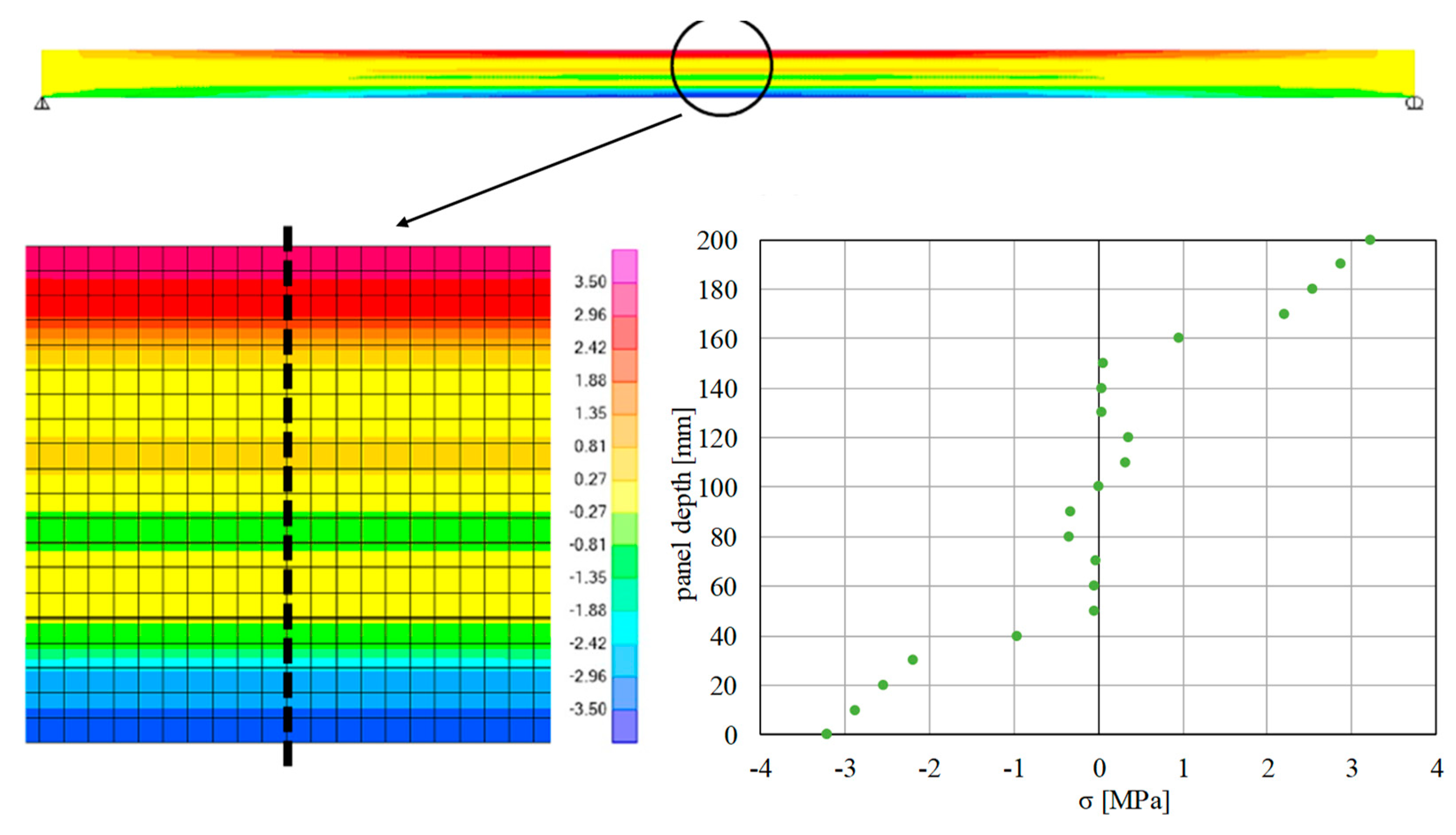
Maximum normal stresses have been evaluated at mid-span of the panels, while the tangential stresses at a distance equal to L/40 with respect to the external supports; this in order to overpass the local effects due to the restrain reactions. For the sake of simplicity, the normal stress distribution given by a numerical model for a case with L/H = 30 is represented in
Figure 6 only. A linear distribution of stresses over the height of cross-section can be noted, with quite a null value in correspondence to transverse layers.
5. Discussion of the Results
The main goal of this paper is to analyze the rolling shear deformation of transverse layers on both deflections and internal stresses of CLT floors at service limit state (SLS). These evalustions have been done using different analytical methodologies currently used in literature, thus also giving the possibility of appreciating the differences between them and to compare the results. With this aim, a parametric study has been developed considering different slenderness span-to-depth (L/H) ratios for CLT panels.
In more detail, deflections and stresses have been evaluated according to the modified γ-method and Shear Analogy Method (SAM), both compared with the results obtained from 2D-shell numerical models (denoted as 2D-shell). In order to better quantify the role of the rolling shear effect, a comparison with the limit case of an infinitely rigid connection (i.e., IR case) has been performed too.
In
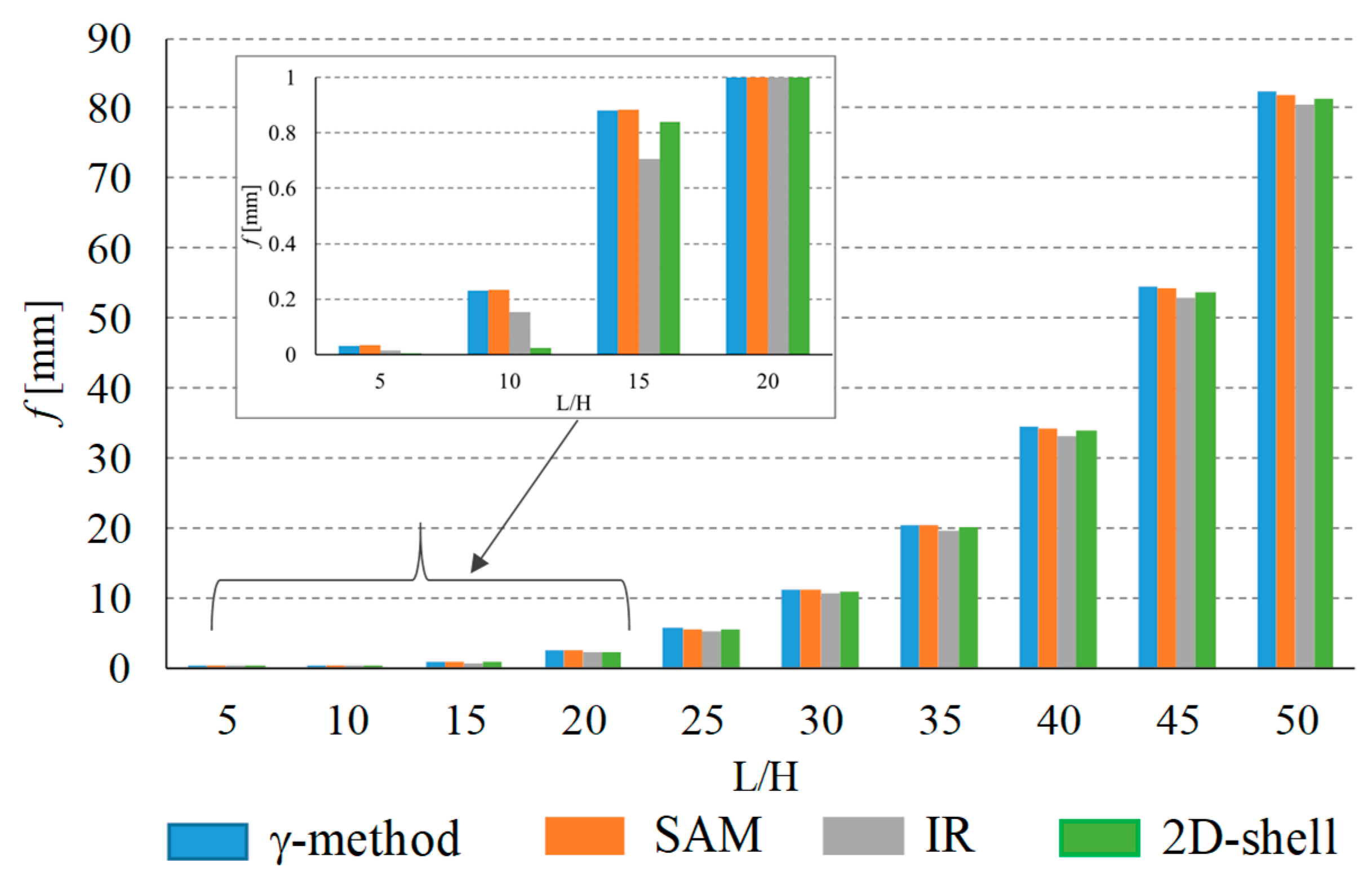
Figure 7, the instantaneous part of deflection (f
inst) evaluated by applying the three considered analytical procedures, for each considered L/H slenderness ratio, is represented. It should be noted that: (a) deflections calculated accounting for the rolling shear effect (γ-method, SAM, and 2D shell- models) are greater than the ones provided by the IR case, especially in the case of low H/L ratios (stocky panels), thus confirming the crucial role played by the transverse layers on the total deflection; (b) both modified γ-method and SAM restitute similar values of deflections, comparable with the ones reinstituted by 2D-shell numerical models.
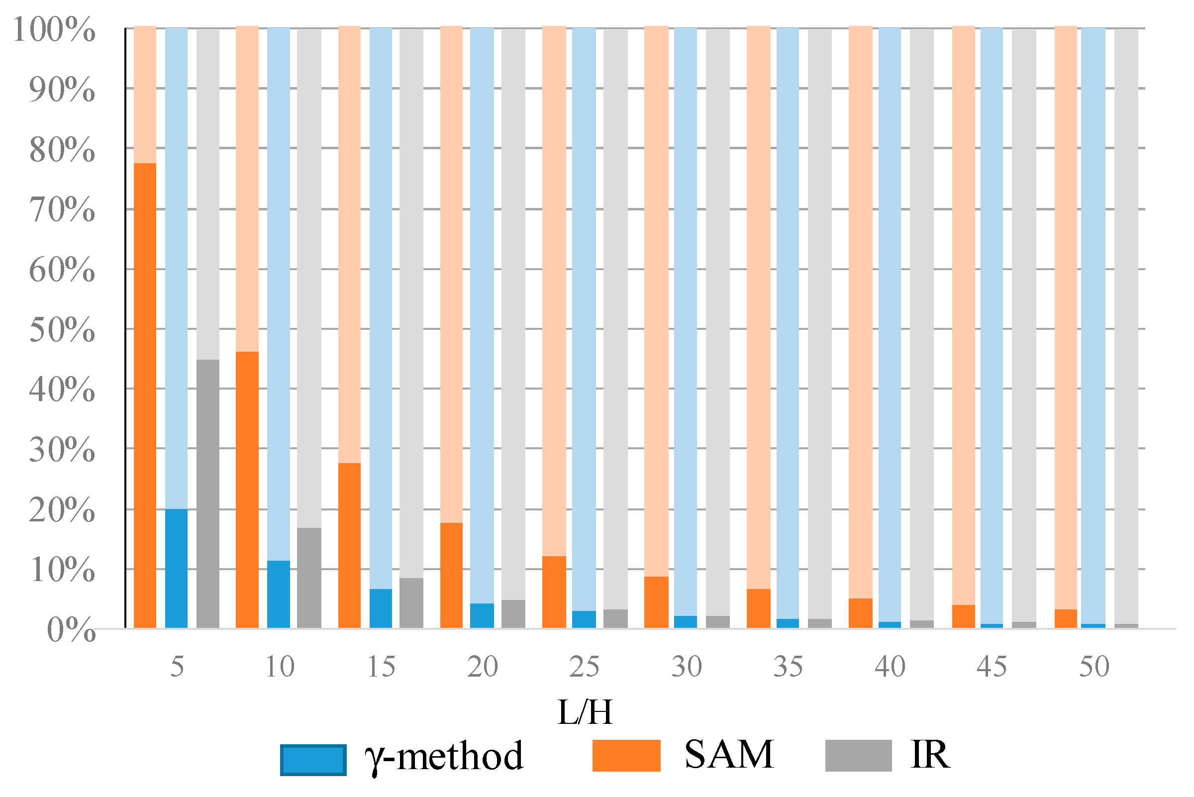
With the aim of better quantifying the rolling shear effect, the percentage contribution of the rolling shear deflection with respect to all of the deflection (flexure and shear) has been investigated for the different L/H ratios. The results are summarized in the graph of
Figure 8. It can be obseved that, as L/H ratio increases, the rolling shear influence decreases, and, in particular for L/H > 30, its influence becomes less than 10%. This result, which is also in accordance to that presented in other literature works [
6,
12], highlights that, for H/L greater than 30, the deflections can be determined disregarding the shear sliding among the layers. The significance of this is that the Eulero–Bernoulli’s hypothesis of the conservation of plain transversal cross-section is a reliable assumption, and, consequently, the calculations can be performed, with good approximation, as for the IR case (
Figure 3).
Moreover,
Figure 8 also highlights that a greater incidence of rolling shear effect on the total deflection is accounted by SAM with respect to the modified γ-method.
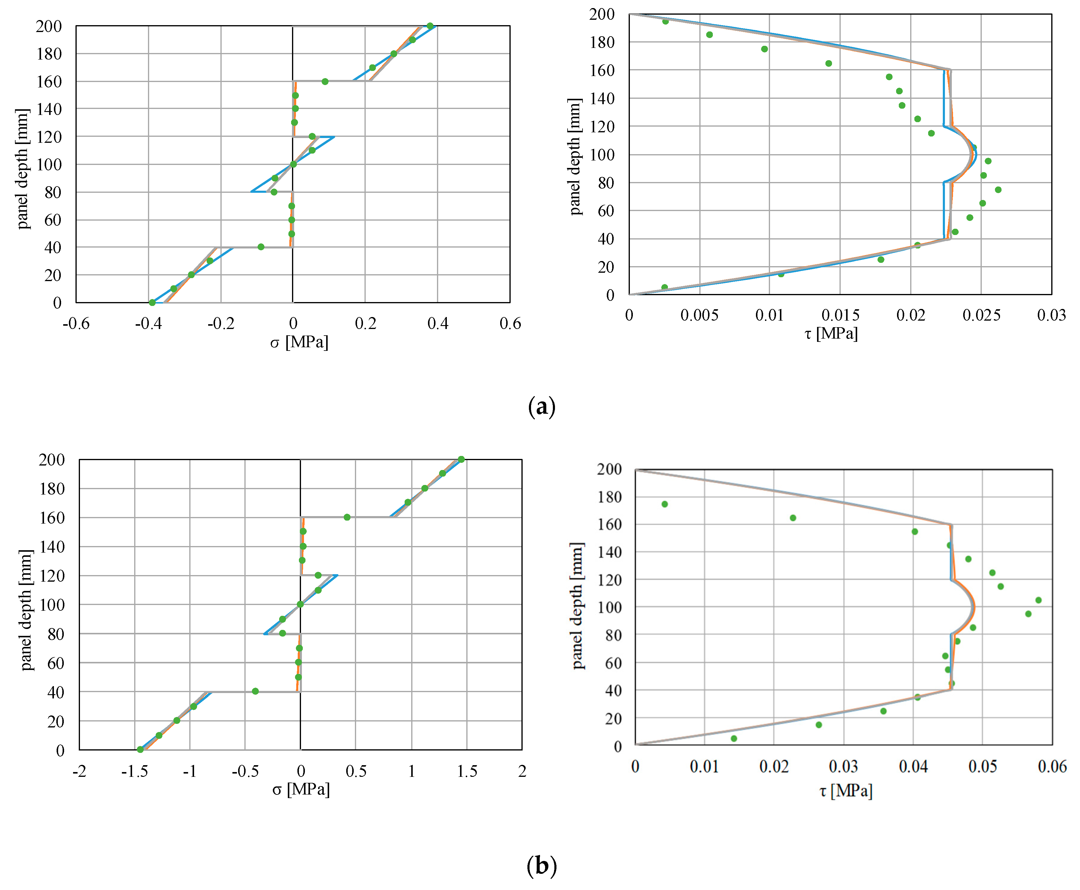
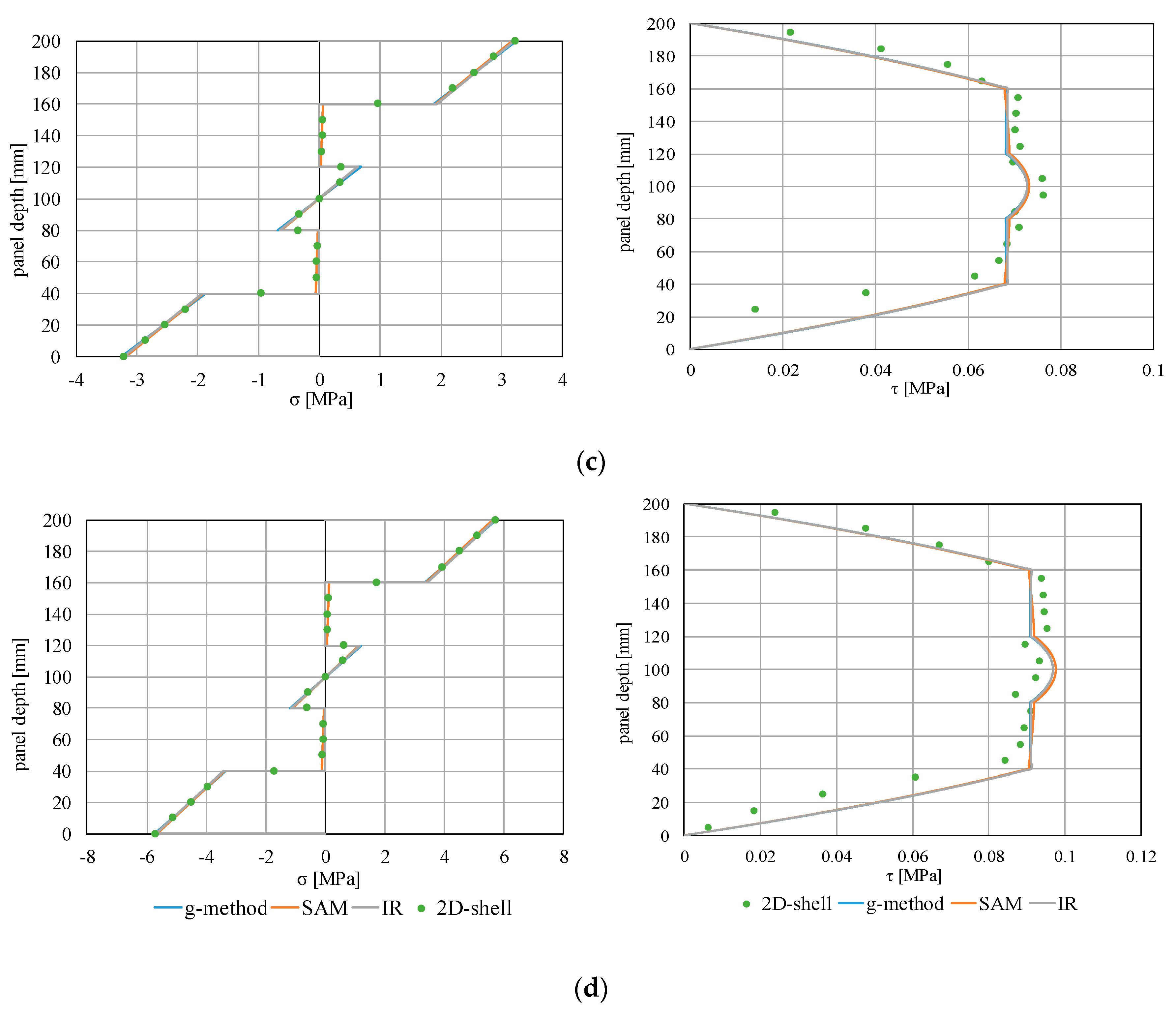
The influence of rolling shear on the stress state has also been investigated by applying both analytical and numerical procedures, and the results have been compared among them. In
Figure 9, the diagrams of normal (σ) and tangential (τ) stresses for the slenderness ratios equal to 10, 20, 30, and 40 are reported. Both modified γ-method and SAM result in values of normal stresses that tend to zero in the transverse layers, for whatever H/L ratio. This achievement is right and is due to the low value of Young’s modulus that affects the transverse layers (E
90) with respect to the Young’s modulus of the longitudinal layers (E
0). Instead, for the case IR, the normal stresses are exactly equal to zero because of the contribution of the transverse layers being completely neglected.
As concerns the tangential stresses, the maximum value is attained in the middle layer of the panels (having grains parallel oriented), while, in the transverse layers subjected to rolling shear, the tangential stresses are constant over their height.
By observing these diagrams, the following considerations can be made:
- (a)
a good matching between modified γ-method and SAM in terms of both normal and tangential stress distributions has been obtained, independently from L/H ratio;
- (b)
a substantial equality correspondence of the normal stresses obtained with analytical and numerical methods can be noted, already for H/L greater than 20;
- (c)
a greater discrepancy of the tangential stress distributions between analytical and numerical approaches results in the case of low H/L ratios (L/H < 20), probably due to the fact that the beam theory—on which the analytical methods are essentially based—tends to fall in the case of shear-dominated elements (stocky elements). Instead, a good agreement among the tangential stress values obtained from the analytical methods, also for low H/L ratios, results.
These latter findings further highlight that, for H/L greater than 30, both the modified γ-method and SAM give back results practically coincident with the IR case, confirming that the rolling shear effect can be neglected for higher slenderness ratios and that the flexural behavior can be analyzed, assuming the case of infinitely rigid connection (IR) as a reference method.
6. Conclusions
The rolling shear influence on the out-of-plane flexural behviour of CLT panels, under service load conditions (i.e., service limit state), has been investigated in this paper.
The majority of existing literature papers have focused their attention on the evaluation of appropriate vaules of rolling shear modulus or on the development of analytical methods and mathematical modeling, while a lack of specific information to be used in practical application is now present.
In this paper, the rolling shear effect has been studied from a more practical point of view. The main goals of the research have been: (a) to quantify the rolling shear influence on both total deflection and stress state of the CLT floor in a service limit state; and (b) to define the rolling shear effect as a function of span-to-length (H/L) ratios typically used in the practical cases. These evaluations have been performed by applying three analytical methods available in literature: Shear Analogy Method, the modified γ-method, and the case with infinitely rigid transverse layers (IR case). The results have also been matched with those obtained by a 2D-shell numerical models of a CLT panel, developed with a finite element software for each H/L considered ratio. This also gave the possibility to compare the effectiveness of different methods in evaluating the rolling shear influence.
As regards deflections, it has been highlighted that, as L/H ratio increases, rolling shear influence decreases. Particularly for slender panels (i.e., characterized by L/H > 30), the rolling shear influence becomes negligible, being less than 10% with respect to the total deflection. This occurrence has been further confirmed by the stress analyses: in fact, for slenderness greater than 30, both normal and tangential stress diagrams, obtained accounting for rolling shear, are practically coincident with those in which this effect has been completely neglected (IR case). In fact, even if SAM and a modified γ-method give back different incidences of the rolling shear deformation, these differences are substantially negligible on global deflections and stress distribution over the height of the cross-section. This means that, in the case of typical span-to-length ratios used in real buildings (i.e., greater that 30), the flexural analyses of CLT floors can be commonly performed by totally neglecting the presence of transverse layers of boards because of truthful values of deflections and stresses being, however, obtained.
On the contrary, for stocky panels (L/H < 20), the rolling shear effect is not at all negligible and its influence must be taken into account accurately adopting a modified γ-method or SAM for evaluating both deflections and stresses.
Finally, a contribution to validate the effectiveness of the modified γ-method has been provided in this paper. In fact, a good matching of a modified γ-method with both SAM and 2D numerical model results.


