Article

Assessing Cement Stabilized Rammed Earth Durability in A Humid Continental Climate

Faculty of Civil Engineering, Warsaw University of Technology, Al. Armii Ludowej 16, 00-637 Warsaw, Poland
*
Author to whom correspondence should be addressed.
Buildings 2020, 10(2), 26; https://doi.org/10.3390/buildings10020026
Submission received: 9 December 2019 / Revised: 14 January 2020 / Accepted: 3 February 2020 / Published: 10 February 2020
(This article belongs to the Section Building Materials, and Repair & Renovation)

Abstract

:
The article compared the test results of a number of features determining the durability of rammed earth durability in a humid continental climate. The results of wet to dry compressive strength ratio, frost resistance, linear shrinkage, resistance to erosion under the influence of a stream of pressurized water, and resistance to erosion under the influence of cyclic wetting and drying were presented. All of the tests were done on the same soil-cement mixture. On this basis, it was determined which of the methods of durability assessment is more and which is less restrictive. A new method for assessing the durability of CSRE in a humid continental climate has been proposed, which is the frost resistance test. This test is determined by the method that is described in the national annex of the European concrete standard of one of the temperate climate countries. The article also shows that a minimum of 9% of the cement additive and a soil mixture containing a gravel fraction are required, in order to ensure adequate rammed earth durability in a humid continental climate (i.e., frost resistance).

1. Introduction

1.1. Rammed Earth

The construction industry consumes up to 40% of the energy demand in developed countries [1]. Therefore, it is worth using building materials obtained locally that do not require transportation and an energy-intensive production process. A building that is made of these materials should be durable under certain environmental conditions. These criteria can be met, inter alia, with building materials and construction technologies while using raw earth. Based on a long history in hot and dry climate zones, raw earth materials can provide new technological solutions in building construction. In countries with cold climates, in addition to a number of technical and social issues, the lack of standards for materials and design is a significant limiting factor for the use of raw earth as a construction material. Especially while considering that the durability requirements will not be the same in different climate zones.
One of the technologies for erecting buildings with the use of locally available soil, which, according to the authors, could be successfully disseminated in a humid continental climate, is the use of cement stabilized rammed earth (CSRE). This technology has an advantage over the traditional production of earth blocks, due to a lower energy consumption [2]. The CSRE process involves compacting layers of the moist earth mixture laid in a formwork set on a stable foundation (Figure 1). The basic component of the soil mixture is the inorganic soil under the humus layer, which is usually taken directly from the construction site. Adding an aggregate and a stabilizer, depending on the grain size of the obtained soil, modifies the soil mixture. The need for cement stabilization is determined, among other things, by the exposure conditions of the rammed earth building and the requirements in terms of mechanical properties [3]. The ingredients are mixed together in an air-dry state and water is then added to ensure that the mixture is sufficiently moist, and therefore able to obtain sufficient workability for compaction by ramming. The layers of the moist, loose mixture are laid in formwork and then compacted with a traditional or mechanized rammer. Once the layer has been properly compacted, further layers are successively added until the planned height of the element is reached. The formwork is then removed. The compaction of layers is intended to reduce the porosity of the material, which involves an increase in its bulk density.
Rammed earth technology is characterized by its low energy consumption and the small amount of waste left over. The components of the soil mixture are widely available, often even locally at the construction site. This minimizes the cost of material acquisition and transport [4]. Therefore, rammed earth has the properties of a sustainable material.
The stabilization of rammed earth is highly beneficial for the mechanical and durability properties of the structure [5]. On the other hand, adding cement to the soil mix reduces the possibility of recycling the material [6]. Furthermore, the stabilization by cement reduces the passive air conditioning ability of earthen walls [7]. The cement industry is one of the two largest producers of carbon dioxide (CO2), creating up to 8% of worldwide man-made emissions of this gas [1]. Therefore, using the minimum amount of cement to reach the required durability performance of CSRE seems to be advisable from the sustainable point of view. The crystalline material’s waterproofing effect in CSRE as well as in concrete is achieved by the reaction of various chemical components contained in the solution when combined within the concrete or CSRE matrix, respectively [8]. The process only works when the porous system of the material reaches a sufficient level of moisture [8]. Contrary to the concrete mix, the CSRE mix is characterized by low humidity at the time of compaction [9]. The durability effect is missing without a sufficient level of moisture inside the material pore structure.
The requirements for rammed earth formulated in standards usually refer to strength characteristics and linear shrinkage, but rarely concern durability. Defining the requirements in this area is related to the particularity of a climate zone and it requires consideration of the main destructive factors that are specific to a given climate.

1.2. Characteristics of a Humid Continental Climates

In global literature, the Köppen-Geiger classification is the most common classification system for the Earth’s climate. This classification is based on values of monthly average air temperatures, annual rainfall volume, and distribution, with reference to latitude. The current version, as described in 2007 by Peel in [10], shows that the humid continental climate is generally found roughly between latitudes 40 N and 60 N, within central and northeastern Europe, North America, and Asia. However, this climate is not found in the southern hemisphere due to a larger ocean area at that latitude and the consequent greater maritime moderation. This climate is characterized by an average temperature of −3 °C or less in the coldest month and an average temperature of the warmest month higher than 10 °C and lower than 22 °C. Precipitation in this climate occurs all year round. In this climate, the frost-free period usually only lasts three to five months [11]. Therefore, the phenomenon of cyclic freezing and thawing is particularly influential among the physical factors that have a destructive effect on building materials in this climate. Another significant factor is certainly the resistance to water, including, noted, and described in the New Zealand standard NZS 4298:1998 [12] the phenomenon of repeated wetting and drying of the surface of the material, causing its gradual destruction.

1.3. Standardized Properties of Rammed Earth

A summary of the properties of rammed earth, described in individual documents, has been prepared on the basis of publications providing an overview of the standards for rammed earth [4,13,14] and on the basis of direct analysis of those standards (Table 1).
A surprisingly small number of documents include requirements regarding durability. On the other hand, in scientific literature there are a number of non-standard features related to durability and ecology, such as hygroscopic performance [7], ecological performance [33], hydrothermal properties [34], and water absorption [35]. The analysis of the table indicates that the most frequently standardized durability characteristics are resistance to erosion and linear shrinkage, regardless of the climatic zone of the country where a given standard was created. It is surprising that the resistance to frost is solely assessed according to US standards. The widest range of requirements is included in standards from New Zealand, and the standardized procedures are accompanied by stringent requirements, even though the country is in a less severe zone than a humid continental climate.

1.4. Aim of the Research

The aim of the research is to determine the minimum cement addition for the use of rammed earth as a building material in a humid continental climate. The laboratory investigation that is shown in the paper was focused on the formulation of strength and durability criteria for the composition of the soil mixture—its grain size and distribution, and cement content—used for rammed earth technology in a humid continental climate. The criteria used for durability evaluation were the following properties: wet to dry compressive strength ratio, frost resistance, linear shrinkage, resistance to erosion under the influence of a stream of pressurized water, and resistance to erosion under the influence of cyclic wetting and drying.

2. Materials and Methods

2.1. Materials

The following materials were used for the experiment: natural loam, sand 0/2 mm, gravel 2/4 mm, cement CEM I 42,5R, and tap water. Sand, gravel and cement meet the conformity criteria for relevant European standards for concrete components. Loam, sand and gravel were chosen for laboratory tests so as to obtain mixtures similar to typical inorganic soils obtained locally on construction sites. The chemical and mineral composition of the loam can significantly influence the characteristics of the hardened material [36,37]. Unfortunately, data on chemical and mineral composition are often omitted in articles on rammed earth materials, which makes it difficult to compare the research results from different sources. For the loam used in the study, mineral composition studies were carried out by the thermal analysis method (thermogravimetric analysis and differential thermal analysis) and chemical composition by fluorescent X-ray spectrometry (XRF). Table 2 shows the mineral and chemical composition of loam used in the tests.
The basic criterion determining the suitability of a soil mixture for rammed earth technology is a limited content of organic substances. Organic soil (humus) is biodegradable, easily absorbs water, and is highly compressible. Therefore, their content in the soil mixture should not exceed 1% of the total weight of the soil [38]. The loam used in this experiment meets this requirement.

2.2. Methods

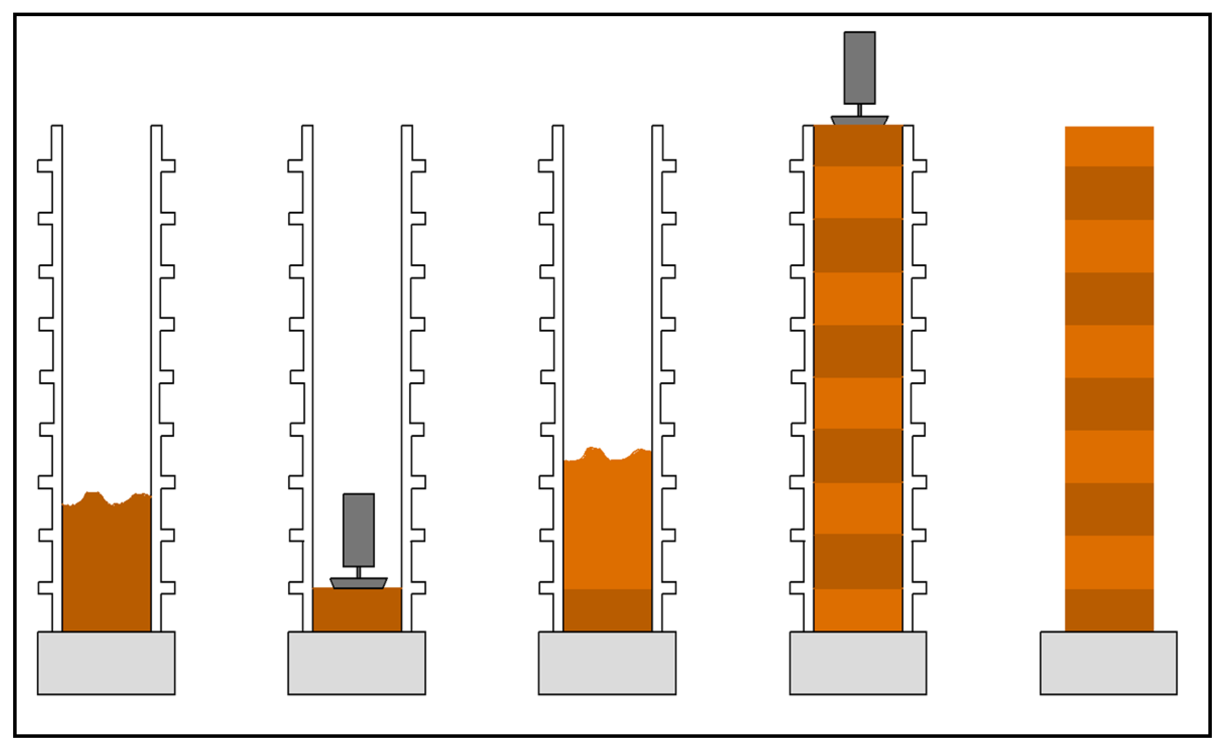
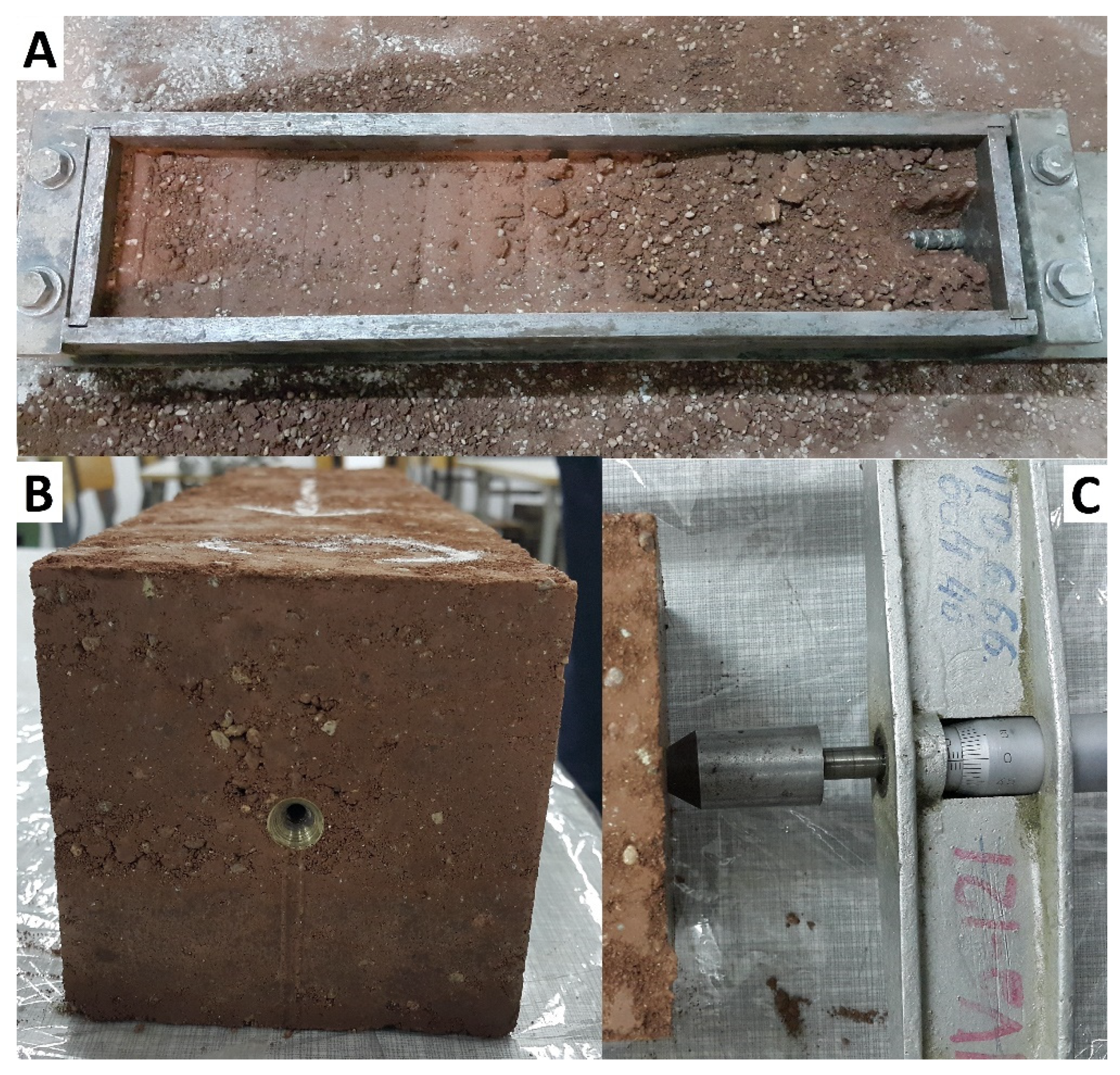
2.2.1. Preparation of Samples

The sample preparation for laboratory testing should reflect, as much as possible, the technology of erecting vertical partitions with rammed earth on the construction site. Therefore, a manual rammer was designed, which could be used as a tool for erecting a load-bearing wall from rammed earth, in order to achieve an earth ramming character similar to terrain conditions. The parameters of the rammer were selected on the basis of the New Zealand standard NZS 4298:1998 [12] and the description of sample formation that was presented by Hall and Djerbib in [39]. The rammer had a weight of 6.5 kg and a surface of 98 × 98 mm. The soil samples were prepared in cubic steel molds of dimensions 100 × 100 × 100mm in order to be able to compare the results of the tested material characteristics with the results of samples made of other popular building materials. The samples were formed by freely lowering the rammer from a height of 30 cm to the surface of the moist soil mixture. A steel guide flange was screwed onto the form to ensure a vertical fall path. The strength test samples were formed in three equal layers, which were compacted by lowering the normal compactor from a height of 30 cm twenty times. The samples to be tested were demolded after 24 h and then cured for 27 days under different climatic conditions, depending on the composition of the mixture from which they were made. The samples from mixtures without cement were conditioned at elevated relative humidity of 75% (±5%) and a temperature of 20 °C (±1 °C). Samples made of cement-containing mixtures were seasoned at a very high relative humidity of 95% (±2%) and temperature of 20 °C (±1 °C).

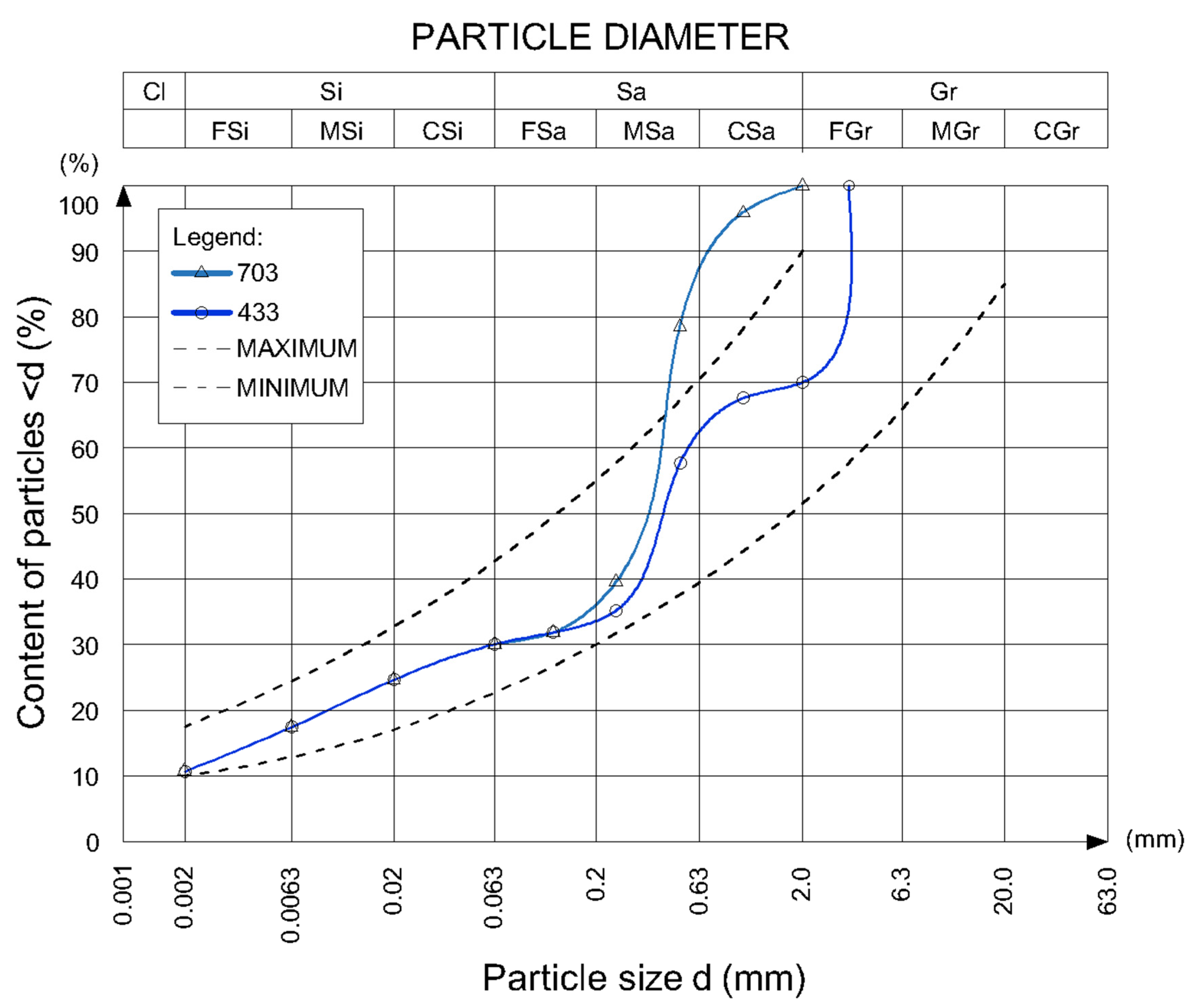
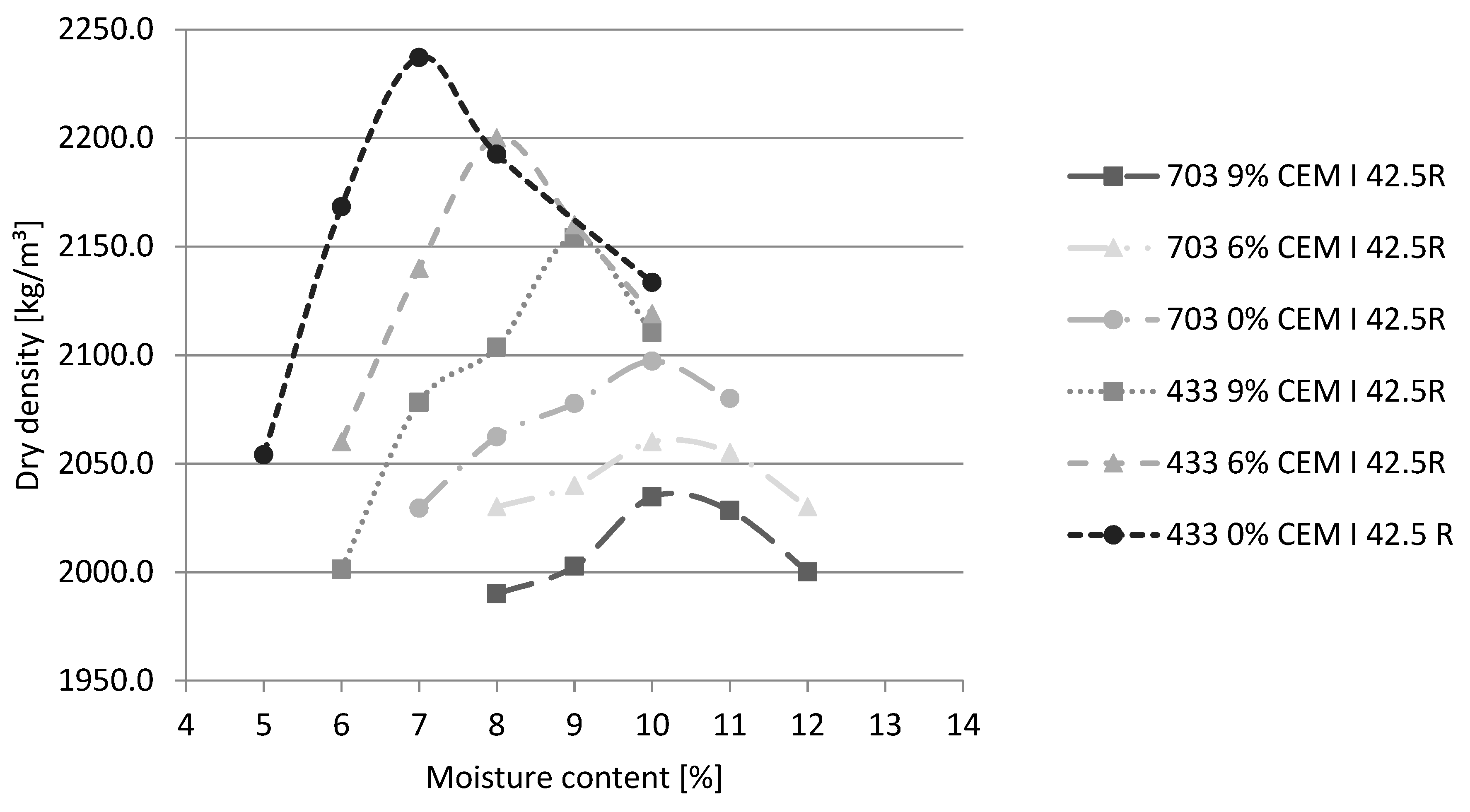
2.2.2. Composition of the Soil Mixtures

Two earth mixtures (Figure 2) with different grain sizes, with the same ratio of silt and clay to sand and gravel fractions of 3 to 7, were proposed on the basis of literature recommendations [13,39,40] concerning the composition of the earth mixture. Mixtures were selected in such a way that one of them had a graining curve within a scope recommended by literature [13,41] and the second one does not contain gravel fractions. Mixture symbols were used to indicate the percentage by mass of the clay and silt fraction, sand fraction, and gravel fraction in the dry earth mixture. For example, mixture 433 contains four mass parts of sand fraction (particles with a diameter of 0.063 mm to 2 mm), three mass parts of gravel fraction (particles with a size of 2 to 4 mm), and three mass parts of clay and silt fractions (particles below 0.063 mm).
The American standard 14.7.4. NMAC [25] recommends that stabilized compacted soil mixes contain at least 6% cement by weight. On the basis of this guideline, it was decided to carry out tests on earth mixtures with the addition of CEM I 42.5R cement in the amount of 6% and, for comparison purposes, on mixtures with the addition of cement in the amount of 9% by the weight of other dry components, as well as for mixtures not containing cement.
Based on the results of measurements of density and water content, compaction curves were prepared, i.e., the correlation between dry density and moisture content for different soil mixtures (Figure 3). The following regularities were observed:
-
the higher the gravel content of the mixture, the lower the optimum moisture content;
-
the higher the content of the clay fraction in the mixture, the higher the optimal moisture content; and,
-
the higher the content of cement added to the mixture, the higher the optimal moisture content.
Samples for testing were prepared from soil mixtures with the addition of water, providing the highest density—the optimum moisture content.
The optimum moisture content (OMC) is the water content at which a soil can be compacted to the maximum dry density by a given compactive effort [43]. In essence, the laboratory testing was aimed at determining the optimum moisture content. The compaction of soil in a standardized manner, with its various moisture contents and measurements of the volumetric density of the soil skeleton, leads to a plot of density vs. humidity function. The resulting graph is called the soil compaction curve [43] from which the maximum volumetric density of the skeleton of the soil to be compacted and the corresponding moisture content can be read.
The nature of the compaction curve, as well as the optimum moisture content for a given soil type, depend on the compaction method and energy used. A method using the Proctor apparatus is a commonly used method of determining the compaction of cohesive soils and their optimum moisture content in a laboratory (according to EN 13286-2 standard [44]). It consists of putting the soil in layers, in a cylinder, with each of them compacted with a specified number of impacts with a rammer to be lowered from a fixed height. The term ’optimum moisture content’ should always be accompanied by a footnote defining the conditions for compaction. In the opinion of the authors, the determination of the moisture content of individual soil mixtures should be carried out as close as possible to the method of compaction of samples that are to be tested. In this way, the samples will obtain maximum volumetric densities, which will have a positive effect on their mechanical properties and durability. Therefore, the optimum moisture content was determined on cubic samples that formed as described in the previous section of the article. Table 3 summarizes the compositions of the soil, cement, and water mixtures used for the tests.

2.2.3. Compressive Strength

The compressive strength of the compacted soil samples was tested in a manner that was similar to that described in EN 12390-3 [45] methods of testing concrete samples. The only difference was that the samples were placed in different ways in the testing machines. Rammed earth, set, and condensed in layers, keeps the layered structure, both in the monolithic wall and in the molded samples. It was assumed that the method of testing the compressive strength, by loading the sample in the direction in which it was rammed, is representative of the determination of the structural resistance, due to the characteristics of the material, as well as the forming technique.

2.2.4. Methods for Durability Assessment and Criterial Values

Among the factors that have a destructive impact on the building envelope, one should point out extreme temperatures, air humidity, intensity of precipitation, the so called “pass through 0°C”, wind pressure and suction, and the action of aggressive factors in the atmosphere [46]. In a humid continental climate, resistance to water and frost determines the durability of buildings made of rammed earth. This issue concerns the construction material, which, in this case, is rammed earth, regardless of how it is protected on the surface. Ensuring durability at the material design level complies with the principle of multi-stage protection (structural protection–material protection–surface protection). The following properties of compacted soil are considered as durability criteria in literature: linear shrinkage, wet to dry compressive strength ratio, resistance to water erosion caused by pressurized water jets, resistance to cyclic wetting and drying, and frost resistance [14,47].

2.2.5. Linear Shrinkage

The tests of rammed earth linear shrinkage were carried out based on the Amsler method described in the PN-B-06714-23 standard [48]. According to this method, measurements are carried out on beams measuring 500 × 100 × 100 mm. The samples were made in rectangular steel molds, laying a mixture of soil in three equal layers and compacting it with a 6.5 kg rammer. The compaction energy per unit volume of rectangular samples was the same as for the cubic samples. After forming the second layer of soil mixture, steel pegs were installed in the geometric centers of the sample heads (Figure 4). Samples that were intended for the linear shrinkage test were seasoned in a relative humidity of 35% (± 2%) and a temperature of 20 °C (±1 °C). Immediately after demolding (after 24 h), the first measurement of the length of beams with the use of Amsler’s apparatus was also carried out with an accuracy of 0.01 mm (Figure 4). The measurements of changes in the length of the beams were carried out for about one year.
According to the review of standards that are shown in [13], linear shrinkage requirements are only included in the German standard [19], the Australian standard [17], and the New Zealand standard [12]. Linear shrinkage requirements are indicated also in the archival Polish industry standard [31] and literature [49]. The majority of these references assume that the acceptable value of linear shrinkage is 2%. The exception is standard NZS 4298:1998 [12], which, for rammed earth, sets the limit value of linear shrinkage at 0.5%. In all standards, the idea of linear shrinkage testing is similar and it consists in measuring the relative change in the length of the specimen over time.

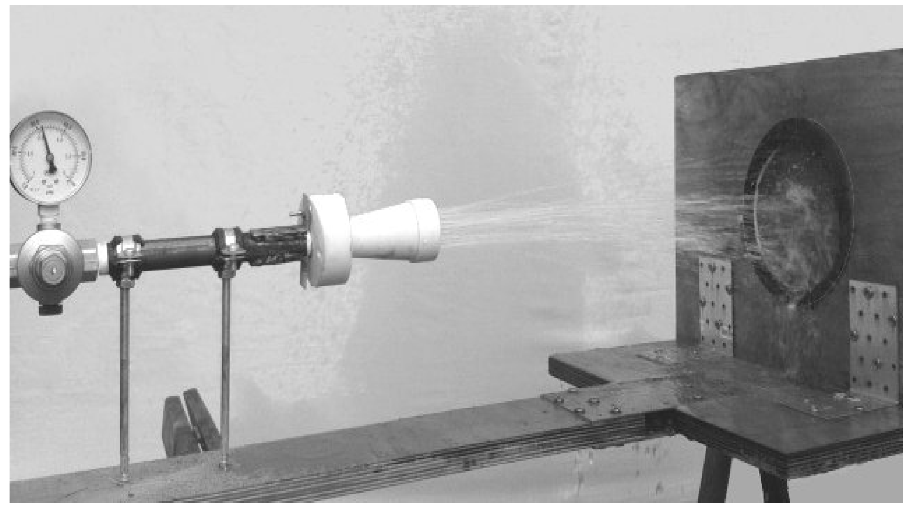
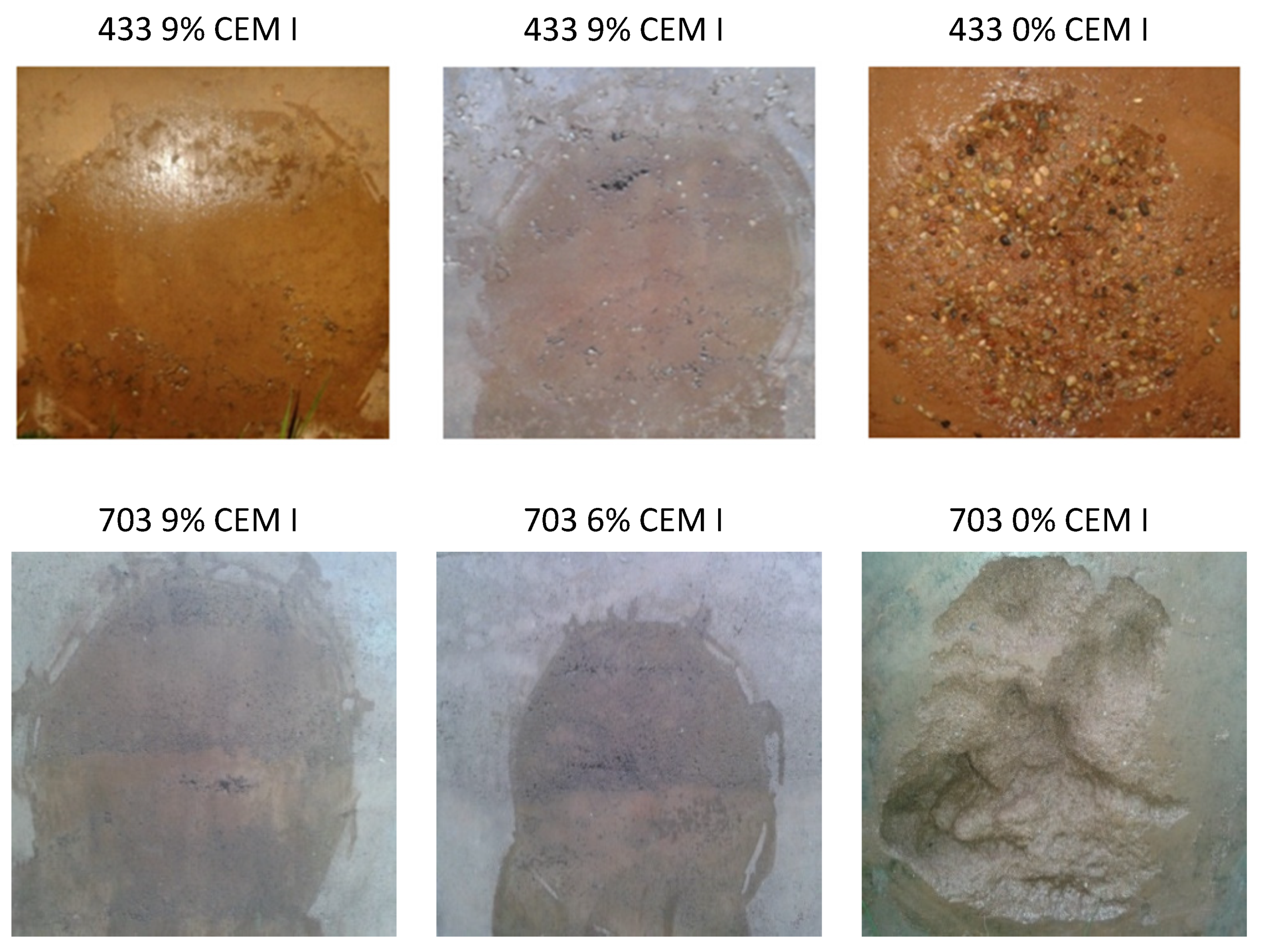
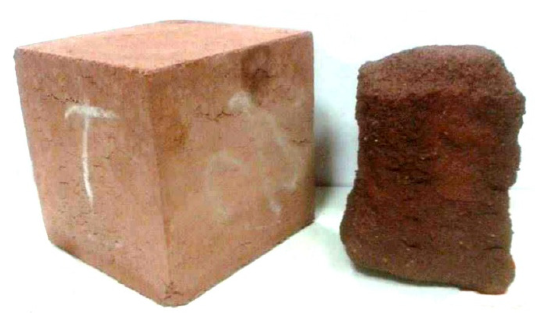
2.2.6. Water Erosion Resistance

A universal test to assess the durability of compacted soil is the resistance to the erosion testing of water, included, among others, in the New Zealand standard NZS 4298 [12]. The first stage consists of measuring the erosion depth of samples that were exposed to water at a pressure of 50 kPa (Figure 5). Based on the depth of erosion that was caused by the water stream, the coefficient of susceptibility to erosion is determined. Based on this, the exposure time of samples in water is determined in the second stage of the method (cyclic moistening and drying of side surfaces of rammed earth elements).
The test described above provides important information on the water resistance of the lateral surface of the material. In external partitions that were made of rammed earth, if no additional waterproofing layer is applied, these surfaces are the most vulnerable to erosion under changing weather conditions—for example, heavy rainfall and subsequent intense solar radiation. For this reason, the method and criterion described above were adopted as one of the tests and requirements for the durability of compacted soil.
Rammed earth might be considered as meeting the durability criteria if the ratio of susceptibility to water is not higher than 2 and, in the visual evaluation, the samples are not damaged after the end of the second stage of the test.

2.2.7. Wet to Dry Compressive Strength Ratio

The wet to dry compressive strength ratio expresses the decrease in compressive strength of the material under the influence of water and it is determined by the formula:
K = Rs/Rd
where:
Rs —compressive strength in a water saturated state
Rd —compressive strength in a dry state
The compressive strength test procedure was the same as described in 2.4.2. The standards for rammed earth do not include requirements for the wet to dry compressive strength ratio. The assessment of the durability of walls made of earth, based on the value of wet to dry compressive strength ratio, has been described by Heathcote in [50], where the recommendations for a minimum ratio between 0.33 and 0.5 have been analyzed and these values were adopted as the criteria in the investigation.

2.2.8. Frost Resistance

Among the standards for rammed earth (Table 1), the frost resistance test was only discussed in the American standard ASTM D 560 [27], which recommends determining the loss in mass and volume of samples that were subjected to 12 cycles of freezing and thawing without providing a criterion for assessing the result. However, the authors would like to propose another procedure for assessing frost resistance. The National Annex [51] has been introduced in Poland (the country is entirely in this climate) in order to adapt the European standard EN 206 + A1 [52] to humid continental climate. This annex introduces additional research procedures, including procedure for testing concrete’s resistance to frost. The basis for this procedure is the assessment of weight loss and the strength decrease of samples subjected to cyclic freezing and thawing. Both methods [27,51] are compared in Table 4.
In [51], both loss in samples mass and decrease in compressive strength are evaluated. The frost resistance test method that is contained in the standard [51] seems to be more rigorous than in [27]. According to [51], the samples are completely saturated with water before the start of freezing and thawing cycles, while, according to [27], the samples are dried to a constant mass. Freezing water in samples increases its volume, leading to faster destruction when compared to dry samples. Ultimately, it was decided to perform the tests in accordance with [51]. The course of the test was monitored every one freeze cycle due to the unpredictable frost resistance of samples made of different mixtures. The test was stopped when the first cavities on the surface of at least one sample from a given series were observed.

3. Results

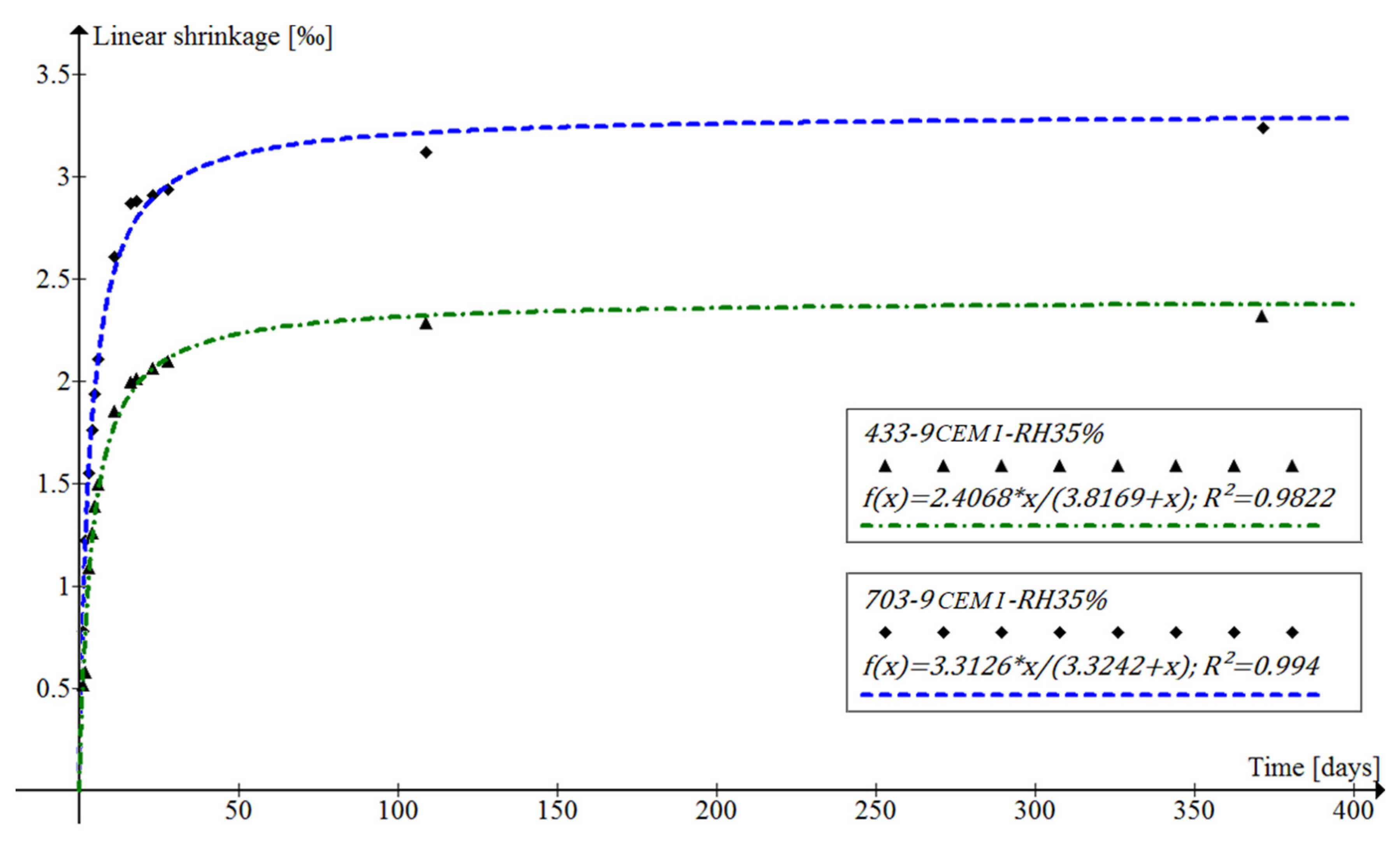
3.1. The Analysis of Linear Shrinkage Deformation Development

The linear shrinkage test was carried out on samples from the mixtures without stabilizer as well as on those containing 6% and 9% cement addition. The linear shrinkage results were measured for each sample series over the year. While using the principles of regression analysis, the empirical mathematical model of the curve was determined using the curve fitting method, which was statistically best suited to the obtained results. The most suitable curve, measured by the R2 coefficient of determination was achieved in the case of the curve in the form of a hyperbola [53]. Figure 6 shows examples of curves for mixtures with a 9% addition of cement. The shrinkage model in this form has a horizontal asymptote whose ordinate is the hypothetical maximum linear shrinkage value of the stabilized rammed earth. On this basis, it can be estimated that the maximum linear shrinkage of the samples from the mixtures will be as presented in Table 5.
A higher linear shrinkage was obtained for mixtures without cement stabilization. When comparing samples with the same cement content, samples from mixture 703 showed higher shrinkage. This could be due to the higher moisture content of those samples, as well as their grain size (no gravel fraction). The most stringent requirement for rammed earth linear shrinkage is contained in NZS 4298:1998 [12], according to which the value after 28 days should be lower than 0.5%. After this period, the studied series achieved a linear shrinkage between 0.21% and 0.29%. It should be mentioned that the testing method according to NZS 4298:1998 [12] is different. The samples are seasoned under a cover for seven days, while the samples that are tested in accordance with [48] are demolded after only 24 h. Analyzing the nature of the linear shrinkage curves of CSRE (Figure 6), it can be seen that the most intense deformation takes place in the first seven days after demolding. Moreover, in the NZS 4298:1998 [12], the samples are not removed from the mold after seven days, but only the cover is removed. Samples that are in accordance with the standard [48] are pulled out of the molds—as a consequence, the evaporation of water can occur over a much larger area. Therefore, if the samples tested have a linear shrinkage after 28 days lower than that allowed by NZS 4298:1998 [12], it can be assumed with great certainty that the most stringent linear shrinkage standard condition has been met.

3.2. Influence of Soil Mix Characteristics on Water Erosion Resistance

The depth of erosion of the samples under the influence of a water jet was tested on samples that were made of six soil mixtures. The results of the first stage (Figure 7) were used to determine the index of susceptibility to erosion and determine the time of exposure in water in the second stage of the study (Table 6). Samples containing not less than 6% cement showed practically no symptoms of erosion.
After the completion of the last wetting cycle (phase II in Table 6), the samples were left to dry for two days and then visually compared with control equivalents—samples that were formed together with the samples tested, but not subjected to wetting and drying cycles (Figure 8, Table 7). None of the samples from the series containing 6% or 9% cement by mass showed any surface damage. All of the samples without cement had deep cavities, despite their shorter exposure time in water due to the determined degree of susceptibility to water erosion. The result of this study leads to the conclusion that, in a humid continental climate, the use of rammed earth without the addition of cement is unsuitable due to the lack of durability. The obtained results also indicate that the granulation of earth mixtures has a secondary effect on the resistance to water. Already a 6% addition of cement by weight provides sufficient resistance to water erosion testing regardless of the grain size curve.

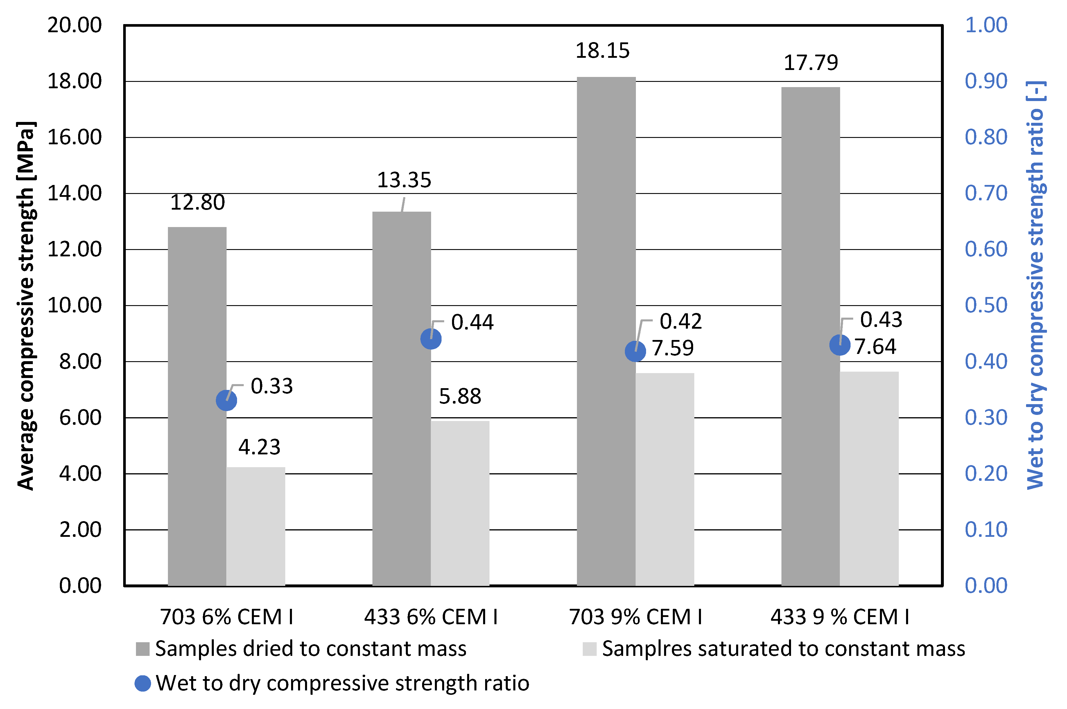
3.3. Wet to Dry Compressive Strength Ratio Investigation

Prior to the rammed earth wet to dry compressive strength ratio test, knowing the results of the water erosion resistance test, which showed that samples without cement are easily destroyed by water, an additional test was carried out by immersing the samples without the cement in water for 30 min. As expected, these samples were quickly and significantly destroyed (Figure 9), so the cement-free compositions were eliminated from the further tests.
During the first 28 days, all of the samples were seasoned under conditions of a high relative humidity of 95%. After that, part of the samples series was dried to a constant mass, while the second part was saturated with water, also to a constant mass. These processes lasted for about seven days—therefore, the age of the samples that were subjected to the compressive strength test was 35 days.
The compressive strength test for water-saturated samples was carried out immediately after they were removed from the water and wiped off, and on dried samples—after they were removed from the dryers. Samples with 9% of cement, dried to solid mass, reached the strength of about 18 MPa, and with 6% cement—about 13 MPa (Figure 10). In the case of samples that were saturated with water to solid mass, stabilized with 9% of cement, the compressive strength was about 7.5 MPa, while for samples containing 6% of cement from 4 to 6 MPa.
Despite the high compressive strength values that were obtained on samples dried to a constant mass, the ratio for all tested series of samples were within the range that was proposed in the publication [50], that is 0.33 to 0.5. The presented study shows how the moisture of rammed earth plays a key role in shaping the basic property of compressive strength. That is why the thermal insulation and finishing layers play an important role in the external wall with supporting layers made of rammed earth. These layers should be arranged in such a way as to eliminate the possibility of water vapor condensation inside the partition.

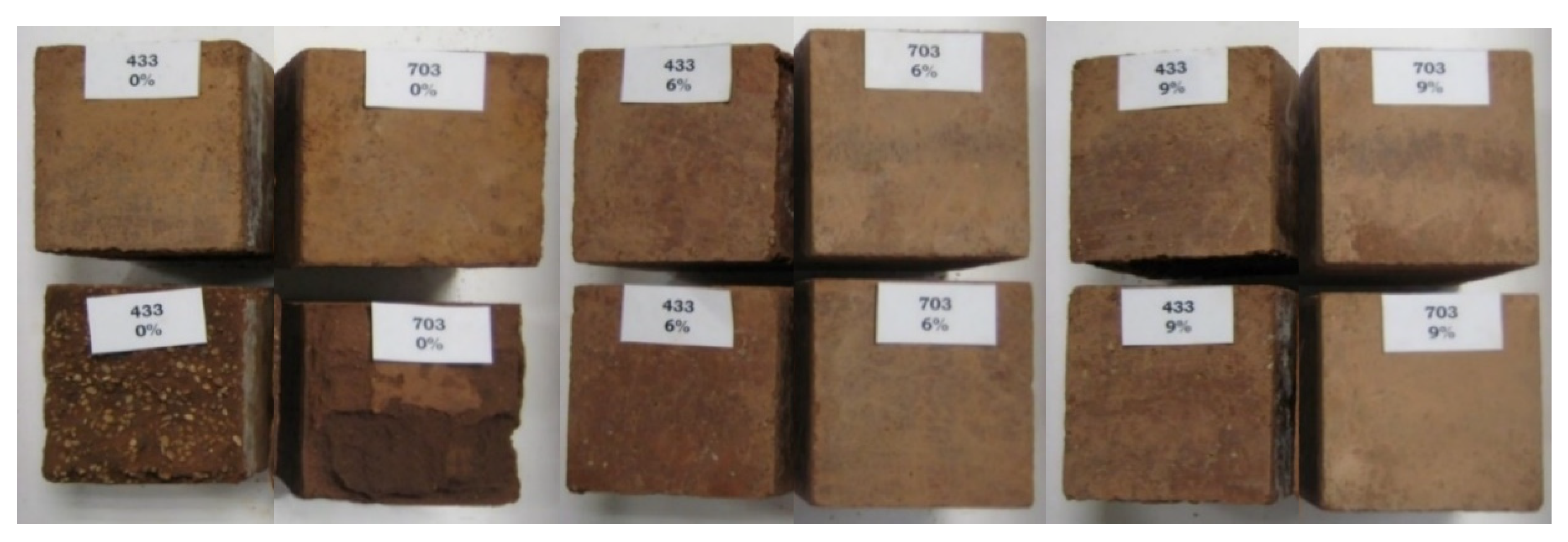
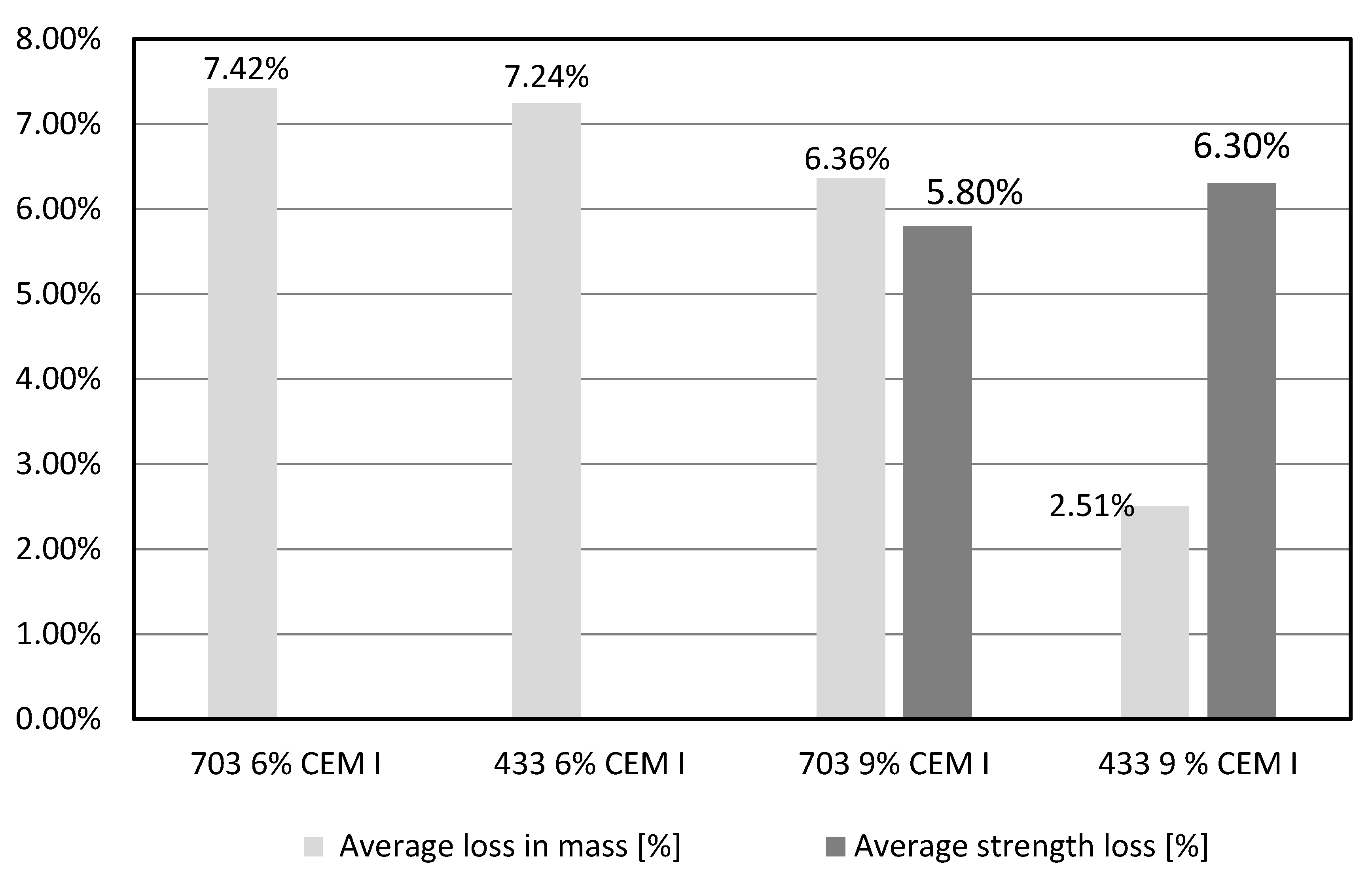
3.4. Rammed Earth Frost Resistance

The frost resistance test was carried out on a series of samples from mixtures 433 and 703 containing 6% and 9% of cement by weight. Out of the four tested series, only samples from a 433 mixture with 9% cement content by weight showed a lower average weight loss than that assumed in [51] criterion (Figure 11). The weight losses reflect the degradation of the individual series. Their erosion, which occurred, to a large extent, around the upper surface of the sample, made it impossible to carry out the compressive strength test for both series of samples from mixtures with 6% cement content by weight. Therefore, only series containing 9% cement by weight were subjected to this test. However, it should be noted that the samples from mixture 703 had already significant mass losses in the upper surface area, which made the strength measurements difficult to accomplish. The decrease in compressive strength for both series of samples containing 9% cement addition turned out to be slight—both series met the standard criterion [51]. Finally, only a soil mixture containing 30% gravel fraction and 9 % cement by weight met the cumulative frost resistance criterion.
Scanning electron microscopy (SEM) analysis of samples from all series were performed before the frost resistance test. The SEM analyses presented below were also performed for the needs of the research presented in [38]. Details of SEM methodology are described in the paper [38]. The SEM images (Figure 12) show the causes of the different results of frost resistance for tested series. When comparing SEM images of the samples with higher and lower cement content, it can be seen that mixes with lower cement content have more cracks. This affects the higher water absorption of the sample with a lower cement content. With the increase in water absorption, the frost resistance decreases. Both in the SEM images of samples 703 9% CEM I and 433 9% CEM I unhydrated cement grains can be seen, however more of them in 703 9% CEM I samples (white fields). This results in lower frost resistance. It is due to the fact that the soil mixture not containing the gravel fraction has higher water demand, which results in a water deficit for hydration of the cement.

4. Discussion

The durability performance results described in [47,50,54,55] and in this paper are hard to compare. The problem is that the CSRE properties depend on many of the soil-cement mixture features that are usually overlooked in the scientific papers. One such feature is the mineral composition, which, as shown in [9], can significantly change the properties of CSRE (Table 8). The presented compressive tests that were made on samples had the same moisture content, sample preparation, curing period, and particle size distribution. As shown, the results differ up to two times.
According to [38], the material characteristics will change depending on the density of elements. sample shape, particle size distribution of the soil used in the mixture, age of the building element, mixture compaction method, moisture content of element during service, moisture content of the soil-cement mixture during construction, content and type of Portland cement, and the exposure conditions of the building element. Hence, the main intention of the presented research was to compare which CSRE durability testing methods are more and which less restrictive.
An analysis of the results of the rammed earth durability tests (Table 9) shows that only the mixture containing 30% of gravel fraction and 9% of cement by weight (433 9% CEM I) met all of the criteria. In the literature, the results of frost resistance of CSRE are not commonly published, while, as it was proved in the article, it is most important factor of CSRE durability.
The assessment of durability based on the procedure for testing concrete’s resistance to frost raises doubts. On the other hand, concrete standards guidelines applicable in humid continental climate can form the basis for assessing material durability. The research results shows that the criterion of durability assessment that is based on the frost resistance test result is more stringent than other popular methods including wet to dry compressive strength ratio [50] and resistance to water erosion [12]. Therefore, in a humid continental climate, it is recommended designing building envelopes in such a way that a CSRE layer is not exposed to external environment. CSRE walls should not be exposed to freezing temperatures unless they were built from soils containing 30% gravel fraction (2–4 mm) and stabilized with 9 % of Portland cement.

5. Conclusions

The research that is presented in the article showed that the frost resistance test is the most stringent durability testing method for CSRE. Since this method is used in practice to assess the durability of a popular building material, concrete, authors suggest using it to verify the durability of CSRE in humid continental climate.
It is recommended to use soil-cement mixtures in with the following characteristics to provide sufficient durability of this material in a humid continental climate:
-
content of 30% gravel fraction (2-4 mm) in the soil mixture, which is confirmed by the recommended grain size are softening index a given in the literature, and
-
stabilization of the mixture with CEM I 42.5 R cement in the amount of not less than 9% of other dry components.
The formulated conclusions refer to mixtures with optimal moisture content and compacted with the use of specific energy. The mineral composition of the soil was also a constant feature of the study and testing. According to the authors, these parameters are important from the point of view of both the strength and durability of cement stabilized rammed earth and it might serve as a basis for further research.

Author Contributions

Conceptualization, P.N. and P.W.; methodology, P.N. and P.W.; formal analysis, P.N. and P.W.; investigation, P.N. and P.W.; data curation, P.N.; writing—original draft preparation, P.N.; writing—review and editing, P.N. and P.W.; visualization, P.N.; project administration, P.N. and P.W. All authors have read and agreed to the published version of the manuscript.

Funding

This research received financial support from the Faculty of Civil Engineering, Warsaw University of Technology.

Conflicts of Interest

The authors declare no conflict of interest.

References

  1. Pérez-Lombard, L.; Ortiz, J.; Pout, C. A review on buildings energy consumption information. Energy Build. 2008, 40, 394–398. [Google Scholar] [CrossRef]
  2. Huberman, N.; Pearlmutter, D. A life-cycle energy analysis of building materials in the Negev desert. Energy Build. 2008, 40, 837–848. [Google Scholar] [CrossRef]
  3. Hall, M.R.; Najim, K.B.; Keikhaei, P. Soil stabilization and earth construction: Materials, properties and techniques. In Modern Earth Buildings; Woodhead Publishing Limited: Cambridge, UK, 2012; pp. 222–255. [Google Scholar]
  4. Schroeder, H. Modern earth buildings codes, standards and normative development. In Modern Earth Buildings; Woodhead Publishing Limited: Cambridge, UK, 2012; pp. 72–106. [Google Scholar]
  5. Hall, M.R.; Swaney, W. European modern earth Construction. In Modern Earth Buildings; Woodhead Publishing Limited: Cambridge, UK, 2012; pp. 650–687. [Google Scholar]
  6. Anysz, H.; Narloch, P. Designing the Composition of Cement Stabilized Rammed Earth Using Artificial Neural Networks. Materials 2019, 12, 1396. [Google Scholar] [CrossRef] [Green Version]
  7. Arrigoni, A.; Grillet, A.-C.; Pelosato, R.; Dotelli, G.; Beckett, C.; Woloszyn, M.; Ciancio, D. Reduction of rammed earth’s hygroscopic performance under stabilisation: An experimental investigation. Build. Environ. 2017, 115, 358–367. [Google Scholar] [CrossRef]
  8. Reiterman, P.; Pazderka, J. Crystalline coating and its influence on the water transport in concrete. Adv. Civ. Eng. 2016. [Google Scholar] [CrossRef] [Green Version]
  9. Narloch, P.; Woyciechowski, P.; Kotowski, J.; Gawriuczenkow, I.; Wojcik, E. The Effect of Soil Mineral Composition on the Compressive Strength of Cement Stabilized Rammed Earth. Materials 2020, 13, 324. [Google Scholar] [CrossRef] [Green Version]
  10. Peel, M.C.; Finlayson, B.L.; Mcmahon, T.A. Updated world map of the Köppen-Geiger climate classification. Hydrol. Earth Syst. Sci. 2007, 11, 1633–1644. [Google Scholar] [CrossRef] [Green Version]
  11. Ahrens, D.; Henson, R. Meteorology Today. In An Introduction to Weather, Climate and the Environment, 11th ed.; Cengage Learning: Boston, MA, USA, 2016; pp. 491–492. [Google Scholar]
  12. NZS 4298:1998 Materials and Workmanship for Earth Buildings; Standards New Zealand: Wellington, New Zealand, 1998.
  13. Jimenez Delgado, M.C.; Canas Guerrero, I. The selection of soils for unstabilised earth building: A normative review. Constr. Build. Mater. 2007, 21, 237–251. [Google Scholar] [CrossRef]
  14. Minke, G. Building with Earth. Design and Technology of a Sustainable Architecture; Birkhäuser– Publishers for Architecture: Kassel, Germany, 2006. [Google Scholar]
  15. Middleton, G.F.; Schneider, L.M. CSIRO Bulletin 5 Earth-Wall Construction, 4th ed.; CSIRO Division of Building, Construction and Engineering: Sydney, Australia, 1987. [Google Scholar]
  16. EBAA. Building with Earth Bricks and Rammed Earth in Australia; Earth Building Association of Australia: Wangaratta, Australia, 2004. [Google Scholar]
  17. Walker, P. HB 195-2002. The Australian Earth Building Handbook; Standards Association of Australia: Sydney, Australia, 2002. [Google Scholar]
  18. NBR 13553. Materiais para emprego em parede monolítica de solo-cimento sem função estrutural; Associação Brasileira de Normas Técnicas ABNT: Rio de Janeiro, Brazylia, 1996. [Google Scholar]
  19. Lehmbau Regeln—Begriffe, Baustoffe; Bauteile: Wiesbaden, Germany, 2009.
  20. IS: 2110. Code of Practice for in Situ Construction of Walls in Buildings with Soil-Cement; Indian Standards: New Delhi, India, 1980; reaff. 1998. [Google Scholar]
  21. IS: 13827. Improving Earthquake Resistance of Earthen Buildings—Guidelines; Indian Standards: New Delhi, Indian, 1993; reaff. 1998. [Google Scholar]
  22. PCH-2-87. Вoзведение малoэтжных зданий и сooружений из грунтoцементoбетoна (ang. Building of Low-Storied Houses with Stabilized Rammed Earth); State Building Committee of the Republic of Kyrgyzstan/Gosstroi of Kyrgyzstan: Frunse (Bischkek), Republic of Kyrgyzstan, 1988. [Google Scholar]
  23. NZS 4297:1998. Engineering Design of Earth Buildings; Standards New Zealand: Wellington, New Zealand, 1998. [Google Scholar]
  24. NZS 4299:1998. Earth Buildings Not Requiring Specific Design; Standards New Zealand: Wellington, New Zealand, 1998. [Google Scholar]
  25. 14.7.4 NMAC. New Mexico Earthen Building Materials Code; New Mexico Regulation and Licensing Department: Santa Fe, NM, USA, 2009. [Google Scholar]
  26. ASTM. E2392/E2392M. Standard Guide for Design of Earthen Wall Building Systems; ASTM International: West Conshohocken, PA, USA, 2010. [Google Scholar]
  27. ASTM. D560. Standard Test Methods for Freezing and Thawing Compacted Soil-Cement Mixtures; ASTM International: West Conshohocken, PA, USA, 2003. [Google Scholar]
  28. ASTM. D559-96. Standard Test Methods for Wetting and Drying Compacted Soil-Cement Mixtures; ASTM International: West Conshohocken, PA, USA, 2015. [Google Scholar]
  29. SAZS. 724. Standard Code of Practice for Rammed Earth Structures; Standards Association of Zimbabwe: Harare, Zimbabwe, 2001. [Google Scholar]
  30. BN-62/6738-01. Masy Cementowo-Gliniane z Wypełniaczami; Wydawnictwa Normalizacyjne “ALFA”: Warsaw, Poland, 1992. [Google Scholar]
  31. BN-62/6738-02. Budownictwo z Gliny—Masy Gliniane; Wydawnictwa Normalizacyjne “ALFA”: Warsaw, Poland, 1992. [Google Scholar]
  32. MOPT Tapial. Bases para el diseño y construcción con tapial; Secretaría General Técnica: Madrid, Spain, 1992. [Google Scholar]
  33. Hall, M.R. Assessing the environmental performance of stabilized rammed earth walls using a climatic simulation chamber. Build. Environ. 2007, 42, 139–145. [Google Scholar] [CrossRef]
  34. Hall, M.; Allinson, D. Analysis of the hydrothermal function properties of stabilized rammed earth materials. Build. Environ. 2009, 44, 1935–1942. [Google Scholar] [CrossRef] [Green Version]
  35. Narloch, P.L.; Woyciechowski, P.; Rosicki, Ł.; Cichocki, D. Ziemia ubijana stabilizowana cementem jako materiał konstrukcyjny—Ocena nasiąkliwości. Przegląd Bud. 2015, 5, 22–25. [Google Scholar]
  36. Hall, M. The Mechanisms of Moisture Ingress and Migration in Rammed Earth Walls. Ph.D. Thesis, Sheffield Hallam University, Sheffield, UK, 2004. [Google Scholar]
  37. Narloch, P.L.; Woyciechowski, P.; Jęda, P. The influence of loam type and cement content on the compressive strength of rammed earth. Arch. Civ. Eng. 2015, 61, 73–88. [Google Scholar] [CrossRef] [Green Version]
  38. Narloch, P.; Hassanat, A.; Tarawneh, A.S.; Anysz, H.; Kotowski, J.; Almohammadi, K. Predicting Compressive Strength of Cement-Stabilized Rammed Earth Based on SEM Images Using Computer Vision and Deep Learning. Appl. Sci. 2019, 9, 5131. [Google Scholar] [CrossRef] [Green Version]
  39. Hall, M.; Djerbib, Y. Rammed earth sample production: Context, recommendations and consistency. Constr. Build. Mater. 2004, 18, 281–286. [Google Scholar] [CrossRef]
  40. Narloch, P.L.; Lidner, M.; Kunicka, E.; Bielecki, M. Flexural Tensile Strength of Construction Elements Made out of Cement Stabilized Rammed Earth. Procedia Eng. 2015, 111, 589–595. [Google Scholar] [CrossRef]
  41. Maniatidis, V.; Walker, P. A Review of Rammed Earth Construction, Innovation Project “Developing Rammed Earth for UK Housing”; Natural Building Technology Group, Department of Architecture & Civil Engineering, University of Bath: Bath, UK, 2003. [Google Scholar]
  42. Houben, H.; Guillaud, H. Earth Construction—A Comprehensive Guide, 2nd ed.; Intermediate Technology Publications: London, UK, 1996. [Google Scholar]
  43. Wiłun, Z. Zarys Geotechniki; Wydawnictwa Komunikacji i Łączności: Warszaw, Poland, 2013; Volume 10. [Google Scholar]
  44. PN-EN 13286-2:2010. Unbound and Hydraulically Bound Mixtures. Test Methods for Laboratory Reference Density and Water Content. Proctor Compaction; Polish Committee for Standardization: Warsaw, Poland, 2010. [Google Scholar]
  45. PN-EN 12390-3:2019-07 Testing Hardened Concrete. Compressive Strength of Test Specimens; Polish Committee for Standardization: Warsaw, Poland, 2019. [Google Scholar]
  46. Arendarski, J. Trwałość i niezawodność budynków mieszkalnych; Arkady: Warsaw, Poland, 1978. [Google Scholar]
  47. Guettala, A.; Abibsi, A.; Houari, H. Durability study of stabilized earth concrete under both laboratory and climatic conditions exposure. Constr. Build. Mater. 2006, 20, 119–127. [Google Scholar] [CrossRef]
  48. PN-B-06714–23:1984: Kruszywa mineralne. Badania—Oznaczanie zmian Objętościowych Metodą Amslera; Polish Committee for Standardization: Warsaw, Poland, 1984. [Google Scholar]
  49. Keable, J.; Keable, R. Rammed Earth Structures: A Code of Practice, 2nd ed.; Practical Action: Rugby, UK, 2011. [Google Scholar]
  50. Heathcote, K.A. Durability of earthwall buildings. Constr. Build. Mater. 1995, 9, 185–189. [Google Scholar] [CrossRef]
  51. PN-B-06265:2018-10/Ap1:2019-05. Concrete—Specification, Performance, Production and Conformity—National Annex to PN-EN 206+A1:2016-12; Polish Committee for Standardization: Warsaw, Poland, 2019. [Google Scholar]
  52. PN-EN 206:2013+A1:2016. Concrete—Specification, Performance, Production and Conformity; Polish Committee for Standardization: Warsaw, Poland, 2016. [Google Scholar]
  53. Woyciechowski, P.; Narloch, P.L.; Cichocki, D. Shrinkage characteristics of cement stabilized rammed earth. In Proceedings of the XXVI R-S-P Seminar Theoretical Foundation of Civil Engineering, MATEC Web of Conferences 117:00178, Bangalore, India, January 2017. [Google Scholar]
  54. Bui, Q.B.; Morel, J.C.; Reddy, B.W.; Ghayad, W. Durability of rammed earth walls exposed for 20 years to natural weathering. Build. Environ. 2009, 44, 912–919. [Google Scholar] [CrossRef]
  55. Narloch PLWoyciechwski, P.; Dmowska, E.; Halemba, K. Durability assessment of monolithic rammed earth walls. Arch. Civ. Eng. 2015, 61, 73–88. [Google Scholar] [CrossRef] [Green Version]
Figure 1. A scheme for erecting a wall using rammed earth technology.
Buildings 10 00026 g001
Figure 2. Graining curves of soil mixtures (703 and 433) used for laboratory tests. (Minimum and maximum—recommended grain size area acc. to Houben and Guillaud [42]).
Buildings 10 00026 g002
Figure 3. The relationship between dry density and moisture content for different soil mixtures.
Buildings 10 00026 g003
Figure 4. Rammed earth linear shrinkage test. (A)—the method of assembling a steel peg after ramming the second layer of the sample. (B)—the location of the steel peg in the soil sample for the linear shrinkage test. (C)—micrometer screw, on which the length of the samples was read with an accuracy of 0.01 mm.
Buildings 10 00026 g004
Figure 5. Measurement of erosion under the influence of pressurized water jet.
Buildings 10 00026 g005
Figure 6. The linear shrinkage curves of rammed earth in conditions of low relative humidity of 35%, depending on the age of the samples and their grain size [53].
Buildings 10 00026 g006
Figure 7. Sample surfaces after the completion of the first stage of the resistance test for water erosion.
Buildings 10 00026 g007
Figure 8. Comparison of samples tested for cyclic moisture and drying (lower row) with their control equivalents (upper row).
Buildings 10 00026 g008
Figure 9. Two samples from a 703 mixture not containing cement. Left: sample not tested for water absorption, right: sample after 30 min of exposure in water.
Buildings 10 00026 g009
Figure 10. Average values of compressive strength of samples dried to a constant mass and completely saturated with water and wet to dry compressive strength ratio for rammed earth with different grain size and cement content.
Buildings 10 00026 g010
Figure 11. Average loss in mass and average strength loss after 25 cycles of freezing and defrosting for samples of rammed earth from different mixtures.
Buildings 10 00026 g011
Figure 12. Scanning electron microscopy images of cement stabilized rammed earth (CSRE) samples containing 6 and 9% of Portland cement.
Buildings 10 00026 g012
Table 1. Characteristics of rammed earth included in the standards. Grey colour indicates standards from countries with a humid continental climate.
DocumentRef.CountryProperties of the Soil mixtureProperties of the Material
Mechanical StrengthDurability
GranulationOrganic substancesSoluble saltsPlasticity Compressive strengthTensile strength Linear shrinkageFrost resistanceResistance to water
CSIRO Bulletin 5, 4th ed. (1995)[15]Australia X X X
EBAA (2004)[16] XX X
HB 195-2002[17] X X X
NBR 13553 (1996)[18]BrazilThe standard does not contain numerical requirements
Lehmbau Regeln (2009)[19]Germany XX X X
IS: 2110 (1998)[20]IndiaX XXX
IS: 13827 (1998)[21]X X
PCH-2-87 (1988)[22]KyrgyzstanX XXX
NZS 4297 (1998)[23]New Zealand X XXX X
NZS 4298 (1998)[12]
NZS 4299 (1998)[24]
14.7.4 NMAC (2006)[25]USAXXX X
ASTM 2392/E2392M (2010)[26]The standard does not contain numerical requirements
ASTM D 560 (1996)[27] X
ASTM D559 (2003)[28] X
SAZS 724 (2001)[29]ZimbabweXXX X
BN-62/6738-01[30]PolandX X X X
BN-62/6738-02[31]
MOPT Tapial (1992)[32]SpainXX X
Table 2. Mineral and chemical composition of loam used in the tests.
Mineral Composition [%]
ComponentClay MineralsIncluding:GoethiteSideriteCarbonatesOrganic substanceQuartz and other
BeidelliteKaoliniteIllite
Content [%]43.78.98.626.2-6.0-050.3
Chemical composition [%]
ComponentSiO2Al2O3Fe2O3K2OCaOTiO2Other oxides
Content, [%]61.7819.6310.653.180.660.890.33
Table 3. Compositions of soil, cement and water mixtures, [kg/m3].
Mixture SymbolSandGravelSilt + ClayCementWater
703 0% CEM I146506280209
703 6% CEM I13910596119211
703 9% CEM I13570582174211
433 0% CEM I8936706700156
433 6% CEM I830622622124176
433 9% CEM I792594594178194
Table 4. Comparison of frost resistance assessment methods contained in ASTM D 560 and National Annex to European standard EN 206 + A1.
TableNational Annex to PN-EN 206+A1 [51]ASTM D 560 [27]
Maturation time of samples28 days7 days
Maturation conditionsTemperature 18 ± 2 °C, relative humidity above 90%Temperature 21 °C ± 1.7 °C, relative humidity 100%
Shape and dimensions of samplesCube with 100 mm sideCylinder 102 mm in diameter and 116.4 mm in height
Preparation of samples for testingSaturation of samples with water to constant massDrying of samples to constant mass at 110 °C
Temperature of freezing the samples−18 ± °C−23 °C
Time of freezing4 h24 h
Time of defrosting2–4 h23 h
Method of defrosting the samplesDefrosting in water with the temperature of 18 ± 2 °CDefrosting in open air
T= 21 °C ± 1.7 °C, RH = 100%
Number of freezing and defrosting cyclesMinimum 25 12
Sizes testedloss of weight in samples
decrease in compressive strength
loss of weight in samples
Criteria for assessing resistance to frostThe samples do not show cracking,
average loss in mass ≤5%,
decrease in compressive strength ≤20%.
No guidelines
Table 5. The linear shrinkage of rammed earth series after one year.
0 % Cement6% Cement9% Cement
703433703433703433
0.46%0.42%0.36%0.34%0.33%0.24%
Table 6. Summary of the results of the erosion survey in Phase I and the assumptions of Phase II.
Test Time, [min]433703433703433703
9% CEM I6% CEM I0% CEM I
Depth of erosion D, mm
151010324
301120933
4512201545
6012202053
Ratio of susceptibility to water erosion111123
Test conditions set for Phase II
Time of water exposure in [min]444421
Number of cycles6
Table 7. Final results of the water erosion resistance test.
Composition of the Soil MixtureCondition of the Surface of the Control SampleStage IStage II
Erodibility Ratio (from Table 7)Time of Water ExposureChanges of the Surface of the Sample after the ExposureResult of the Verification Phase
433 0% CEMno damage26 × 2 mindeep losses on the surface of the whole samplenegative
703 0% CEM36 × 1 min
433 6% CEM16 × 4 minno damagepositive
703 6% CEM
433 9% CEM
703 9% CEM
Table 8. Mineral compositions of soil mixtures given in percentages. The table also gives the percentage of water and CEM I 42.5 R cement additions and the average obtained compressive strength of CSRE samples in each series.
Mixture SymbolMontmorillonite [%]Beidellite [%]Kaolinite [%]Illite [%]Goethite [%]Siderite [%]Calcite [%]Organic Substance [%]Quartz and Others [%]Cement Addition [%]Compressive Strength [MPa]
MC III 6%0.06.61.90.00.90.013.10.177.366.96
MC III 9%98.76
MC IV 6%0.00.021.80.00.30.00.00.177.864.51
MC IV 9%95.63
MC V 6%0.00.021.10.00.00.00.00.178.764.30
MC V 9%95.45
MC X 6%3.04.16.92.90.01.10.00.481.763.60
MC X 9%94.27
Legend [%]0.1–11–55–1010–25>25
Table 9. Summary of research results. Green color is used to indicate mixtures that meet the criteria for a given characteristic of durability in temperate climates.
Criterion and Critical Value0 % Cement6% Cement9% Cement
703433703433703433
Linear shrinkage < 0.5%0.46%0.42%0.36%0.34%0.33%0.24%
Resistance to water erosionRatio of susceptibility to water erosion ≤ 2321111
Surface condition after exposure to waterDeep losses on the surface of the whole sampleNo damage
Wet to dry compressive strength ratio > 0.33Not tested0.330.440.420.43
Frost resistance after 25 cyclesCompressive strength decrease < 20%Not tested100%100%5.8%6.3%
Mass loss < 5%Not tested7.24%7.24%6.36%2.51%

