1. Introduction
Recently the development of urbanization has accelerated, and it is caused by the rapid increase in urban population. By now, more than 50% of the people live in cities. This percentage is expected to grow, and by 2030, it may reach 60% [
1,
2]. For Hungary, this value is close to 70%. As a result of this change in the pattern of life, with the disturbance in the ecological structure, existing green spaces are gradually removed, affecting the urban climate and creating an unfavorable phenomenon [
1,
3,
4]. Urban heat islands (UHIs) occur in cities, where the air and surface temperatures are higher than in the surrounding rural areas [
5,
6].
The effect of UHIs can be seen everywhere in the densely built-in downtown environment. Satellite measurements over the ten largest cities in Hungary have shown that the difference between the average temperature in the city center and the suburbs is 3–4 °C in spring and 4–6 °C in summer. In autumn, it decreases to a difference of 2–3 °C [
7]. The presence of photochemical smog makes this process worse.
Regarding the available solution to reduce the impact of UHIs, an increase of green areas and the use of green structures integrated into the facade and roof of buildings are the primary tools. Indirectly, the reduction of heating and cooling energy consumption mitigates the impact of UHIs, as well as the passive and active use of solar energy, and reduces the energy consumption and emissions of buildings.
Having a significant impact on the architectural approach, UHIs affects the design of the urban environment not only regarding used material but also from the consumed energy point of view. The growing demand for cooling in buildings exacerbates the energy consumption that leads to an increase in CO
2 emissions [
8,
9]. There is a bigger focus on the energy performance of urban settlements, and it seems to be the main task to be solved concerning sustainable buildings in the future [
10].
The importance of savings in building energy encourages designers to implement new strategies in the design and reconstruction of buildings improving the livability in the cities [
11]. The effects of UHIs on the energy consumption of buildings have been widely investigated [
12,
13]. Relying on the results of previous studies, it can be stated that the effect of UHIs on building energy consumption is worth mentioning, taking into account the design of façades. Furthermore, the performance of windows greatly affects the energy efficiency of the buildings [
14].
2. Materials and Methods
Environmental loads associated with the operation of buildings can be mitigated in the heating season by reducing heat losses and realizing solar gains. In summer, by increasing the heat losses and preventing the ingress of heat load into the building, proper comfortable conditions can be provided in the internal spaces of the building without operating engineering equipment or with the application of low energy systems.
The most significant means in reducing energy use is that the spatial partitioning (façades and roofs) of buildings becomes suitable for passive and active solar energy utilization. In the case of existing buildings, taking all of these aspects into consideration requires careful design steps.
The question emerges, what kind of opportunities can be considered in the case of existing historical buildings to reduce the energy consumption and heat loss of buildings, as well as how façades could contribute to utilizing solar energy, increasing the comfort of the interior in the summertime while preserving the image of the building.
The regular means of reducing heat loss (decreasing the surface/heated volume ratio, orienting towards a favorable cardinal direction, and increasing the heat storage capacity) may not be enforced for existing buildings. However, increasing the thermal insulation capacity of windows, reducing ventilation losses with a designed ventilation system, and using shades associated with doors and windows may provide a good tool. Solar energy can be actively utilized with solar panels integrated into the window structure.
2.1. Energy Conscious Reconstruction of a Box-Type Window
In Hungary, box-type windows are still present in a significant part of the pre-1960 building stock. These double-skin wooden windows appeared in the 18th century, with sashes opening outwards and inwards. In the 19th century, they became a commonly used structure, first in aristocratic palaces and then in town halls and public buildings [
15]. Windows were generally designed in 2 × 3 or 2 × 4 divisions. At the end of the 19th century, the box-type of window with only inward-opening sashes gained ground (
Figure 1), and were built into a ½ brick-width stepped wall reveals. There was an arched or straight vault above the window opening, where iron beams were used as a lintel in the last third of the century. The window profiles are very slim, with a thickness of 43–45 mm and often supplemented with a decorative profile. Single (2–3 mm thick) glass panes were placed in the sashes, with the distance between the outer and inner sash being about 80–180 mm. The two frames are connected by a 10–20 cm thick casing, thus forming an air layer between the glazing panes. Due to the inward opening, the inner sash is wider and taller than the outer. The window opening was often designed with an architrave that included an internal, accordion-like movable shading panel. The box-type windows have a double-face covering the frame-sash connection.
2.2. Reconstruction Methods, Literature Results
Renovating a large number of box-type windows has lately become a very important task. The thermal transmittance of these windows is U = 2.80 W/m
2 K [
16]. At the same time, several studies prove that the energy properties of these box-type windows are significantly better.
Baker et al. [
17] did research on retrofitted traditional windows called Historic Scotland and English Heritage sash and case windows in laboratory and in situ circumstances. Their measurements consisted of single-glazing replacement to double-glazing, or applying secondary glazing and several types of blinds and shutters, and measuring thermal performance. Their analysis results showed the air-tightness improvements of sealing and the retrofitting versions.
Numerous studies deal with thermal performance and airflow modeling of doors and windows by computer simulation, which provides useful conclusions for determining the direction of developments. Bakonyi and Dobszay [
18] used EPICAC-BE and MATLAB-based dynamic simulations to calculate the energy balance of traditional Central European box-type windows. Based on the results confirmed by instrumental measurements, different renovation variants were examined. In their results, they also demonstrated the winter-summer effectiveness of an intermediate shading device between the sashes.
Norwegian researchers [
19] have studied in detail the renovation solutions of the traditional single-glazed single casement-sash windows by adding a new casement structure and supplementing the frame structure. The new casement was also tested with single- and double-glazing, and the distance of the additional structures from the original ones were other variants. For the determination of U-values, the software THERM6.3 was used, while the variations for the total transmission factor, g, and the light transmission factor, LT, of glazing were calculated with WINDOW6. Their results showed that a double casing structure (74 or 144 mm distance between casements) with an insulating glass unit in the outer casement without Argon gas was better than in a newly manufactured window where the distance between the elements is small. It was recommended to leave an air opening at the outermost casement to give a “self-drying potential” to prevent condensation. Measurements have shown that the holes for airing do not cause a significant increase in U-value, for which it is sufficient to remove a few cm of sealing tape at the top and bottom. An interesting result is that the gap tightness at the connecting of structural elements had a much more critical effect on the value of sound insulation than on the thermal transmittance.
Asphaug and his Norwegian colleagues [
20] investigated ventilation to aid drying within the window structure (as was mentioned above). The introduction of outside air between the external and internal casements gives the window a “drying capacity”. At the same time, the U-value of the window and the development of humidity conditions depend on the ventilation in the air gap. Ventilation was simulated with the WUFI
® software (Pro 5.3
www.wufi.de) to realize under which climatic conditions there was a risk of condensation. Their results were presented for modern multi-layer thermal-insulated glazing windows, but the methodology could be applied to traditional window renovation design.
In their publication [
21], Smith and colleagues examined the results of supplying a secondary glazing layer to typical New Zealand single-glazed window structures using WINDOW6 software. The thermal performance of four types of posteriorly fixed glazing with different layers was measured under laboratory conditions.
The ratio of glazing to frame and the length of linear thermal bridges due to the connection of the opening wings degrade the thermal insulation capacity of the window. The results of a mathematical calculation model in publication [
22] based on the function of the number of sash and lites, could provide practical help to both designers and users.
Lai and Hokoi [
23] summarized the structural versions of solar façades published between 2010 and 2015 for building integrated photovoltaic (BIPV) and thermal building integrated photovoltaic (BIPV/T) systems, which were grouped as opaque and transparent or semi-transparent façades.
2.3. Energy Conscious Reconstruction of a Box-Type Window
The fundamental requirements for the reconstruction of these windows are that they preserve their historical nature, retain their geometrical proportions, and if they are replaced, they shall resemble the design and construction of the original box-type windows. Thus, this could be implemented by following the different reconstruction cases mentioned below:
The simplest case is when the original frame and external sash casements can be renovated. There have been attempts to maintain and renovate the box-type window structure and to apply a shading between the glass panes that can significantly reduce heating and cooling energy requirements. For example, during the reconstruction preparation for the headquarter of the Hungarian Academy of Sciences (MTA), it was proved that the box-type window structure with significant heat transfer and high g value combined with a suitable shading between the glass panes could reduce the heating/cooling energy demand even better than a modern window structure [
24,
25].
If the structure is in good condition, the single pane would be replaced with an insulating glass unit. Due to the small profile thickness, a single glass pane is 3, possibly 4 mm thick, so a structural design of 3/4–6/3 mm gas-filled unit may be installed where the inner layer has a low-e coating on it, e.g., Histoglas. With these, the thermal transmittance is U = 1.3–1.9 W/m
2 K, sound reduction is R
res = 34 dB [
26]. With a 3/6/3 mm glazing structure, an improvement of up to 35% could be achieved. The glazing of the renovated outer sash remains 4 mm float glass.
If the condition of the structure does not allow the former renovation, it would be reproduced with profiles of identical dimensions of its original sections, but with greater thickness. However, the profile reinforcement is unavoidable due to the increase in the mass of thicker insulating glass units compared to a single pane.
When the window can be converted into a basic type of double-skin transparent façade, an option for passive solar energy utilization is ensuring proper airflow between the structural layers [
27]. This is called a box-type window (Kastenfenster) in the German literature.
The purpose of the renovation of the box-type windows is to meet the requirements of modern structures while preserving their image, and to create an adequate state of comfort in the interior in both winter and summer. Shading plays a significant role in this aspect. Properly designed, mobile blinds provide both sun protection and thermal protection. After reconstruction, a window is also a tool for passive solar energy utilization, so the airflow must be planned. In order to keep the airflow, a sealing profile should be placed in the rebate at the connection of the sash and the frame.
2.4. Experimental Design of a Box-Type Active Window
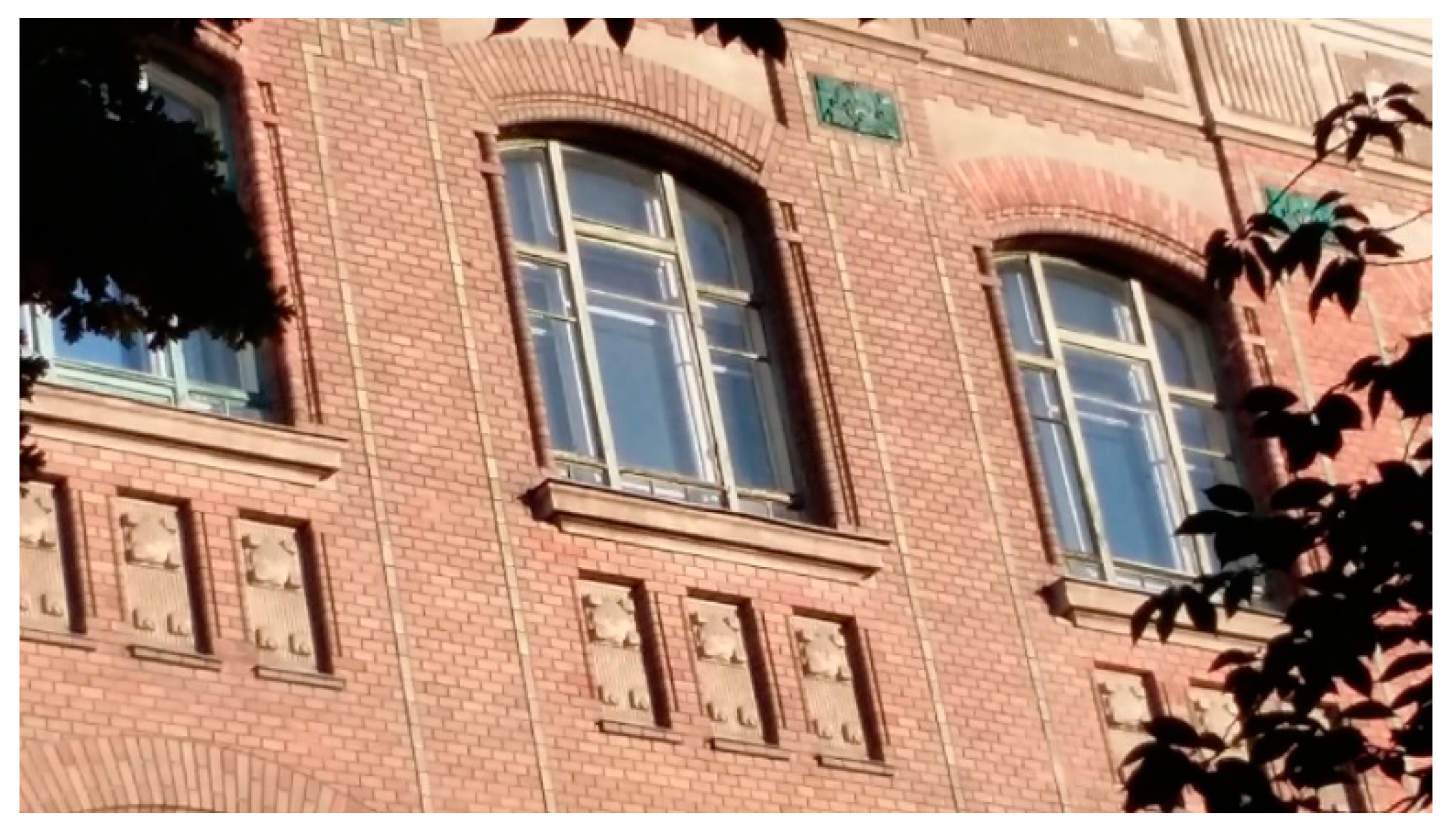
One of the traditional box-type windows of the Central Building (
Figure 2) located on the campus of the Budapest University of Technology and Economics (BME) was selected for experimental design. The predecessor of the university, the Institutum Geometrico-Hydronchnicum, was founded by Emperor Joseph Habsburg in 1782 but took its final position between 1904 and 1909 on the campus [
28]. Alajos Hauszmann, a renowned architect of the millenium, was in charge of the design and building process [
29]. The Central Building is one of the most important monuments on the banks of the Danube. The main façade of this symmetrical building is about 200 m long, and its central bay axis shows the main entrance of the building.
Haussmann’s intention was to make the building “…a memorial-style work worthily documenting the advanced level of contemporary architectural art in Hungary” [
30]. Thanks to the excellent plan, the Central building of the campus still fulfills the constantly changing requirements. The impressive dimensions of the building are also reflected in the quantity of window-types covered by this article, since there are 246-246 pieces on the Eastern and Western façades, while 228-228 pieces are on the Southern and Northern façades.
A pilot project is currently under preparation at the BME with the aim of developing the original windows (shown in
Figure 3) to an active combined window.
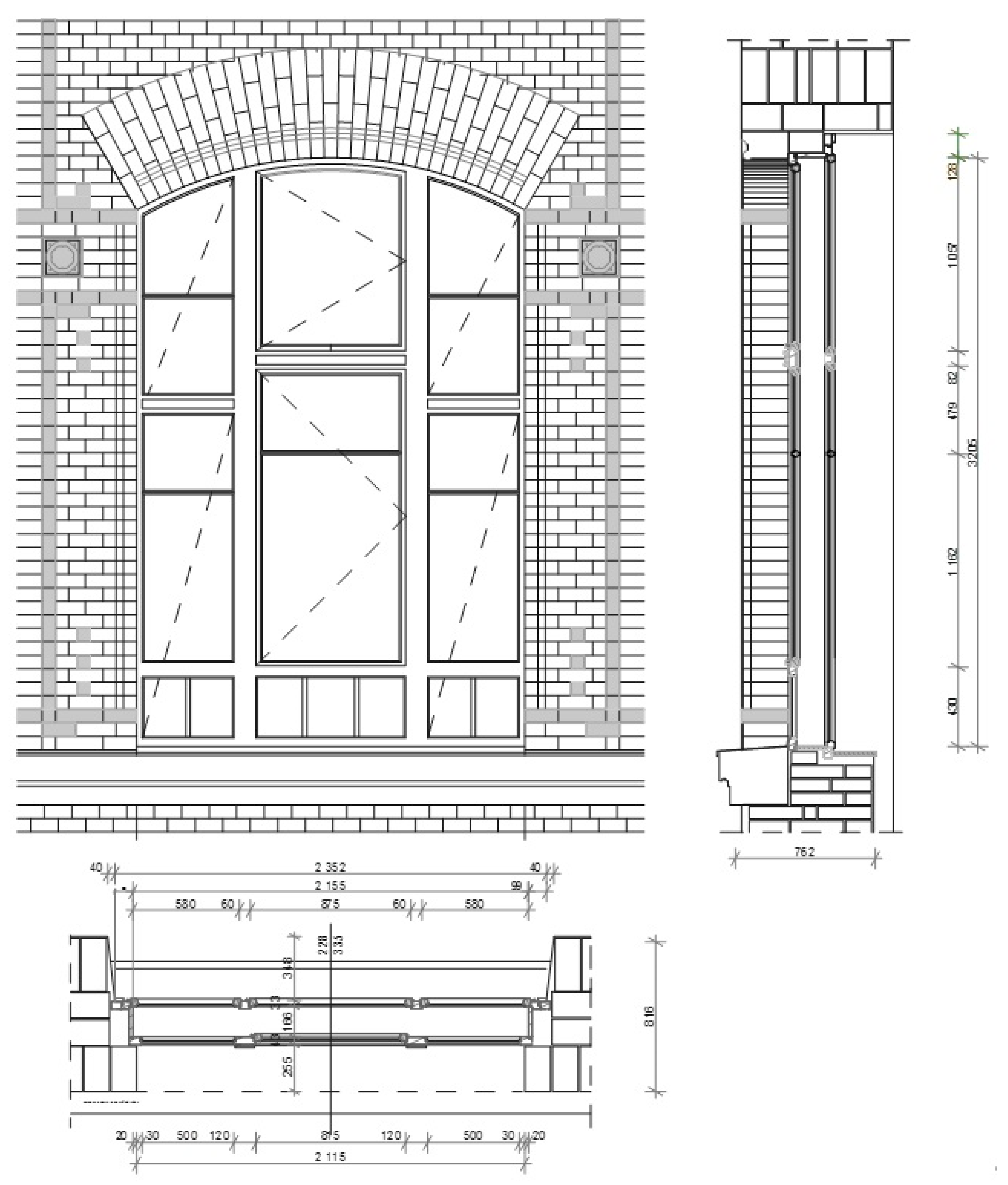
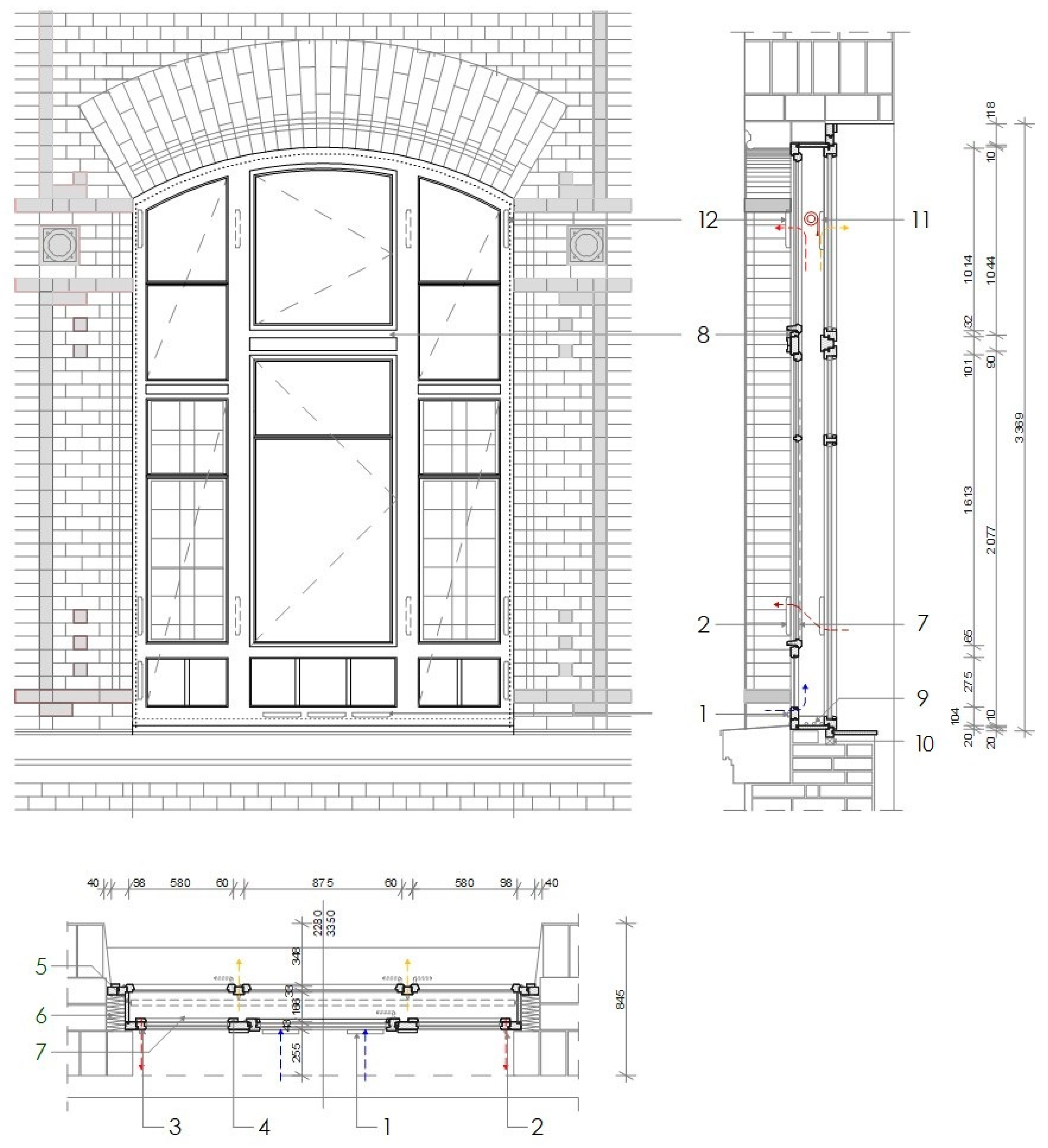
The designer of the reconstruction works in the Central building is György Stocker, while the design schemes for the pilot window were prepared by Péter Medgyasszay and Valéria V. Horn. The project is designed to demonstrate the efforts that may be and should be made in the case of historical buildings to reduce the heat losses during the heating season, to minimize the risk of overheating during summer, and to convert the façade surface energy production. The designed combined box-type window does not only use solar energy in a passive way, but a low level of electric power generation is also possible with the help of the installed solar panels. Like the majority of the windows in the building, the selected one for future reconstruction is installed in a wide jamb wall with overall dimensions of 2300 × 3500 mm (
Figure 4), where the room has an internal height of about 5.5 m.
The elements of the window are warped, there are significant cavities in the connections, and the stack effect is not negligible. During the summer of 2017, on weekdays in the morning and at noon, the air temperature, the temperature between the glass and the glass surface temperature were measured continuously with thermometers. Thus, the selected window was located on the southern elevation, and during summer heat-waves, the surface temperature of the external glass surface could rise even above +50 °C, while the temperature of the air between the two glazings may reach +55 °C. The indoor air temperature in the room often reached 32–34 °C, which eventuates difficult working conditions for the employees of the university. The design of the window reconstruction work was started by the consideration of the above-mentioned conditions. The survey of the window was documented with ArchiCAD (21, Graphisoft, Budapest, Hungary).
2.5. Description of the Window Reconstruction
Based on the structural condition of the window and the methods known from the literature, using the results reported in publications, the following interventions are planned in the window reconstruction works:
Making the external frame and sash thicker in order to avoid the weakening of the cross-sectional dimensions due to the air inlets for ventilation to be installed; the replacement of the decayed components, drip edge design.
Renovation of the external sash frames using a single layer of 4 mm thick float glass.
The inner sash frame of the box-type window is to be newly manufactured using a gas-filled low-e coated 4/10/4 mm insulating glass unit. The three layers of the two sashes could jointly provide the heat transmission coefficient required for newly built doors and windows (the requirement in [
31] is U
window = 1.15 W/m
2 K).
Installation of the hardware, identical with the original one (turning rod lock, clutch, remote opener, copper handle); surface finish identical with the existing one, painting in cobalt green on the outer side and white colors inside and between the intermediate space. The renovation design of the window elements is to be carried out according to the VFF guidelines [
32].
Installation of motor-driven air inlets, solar panels, and automatic control devices.
Installation of shading structures.
Following the above-mentioned steps in the reconstruction process, the designed structure to be created was called the combined window.
3. Results
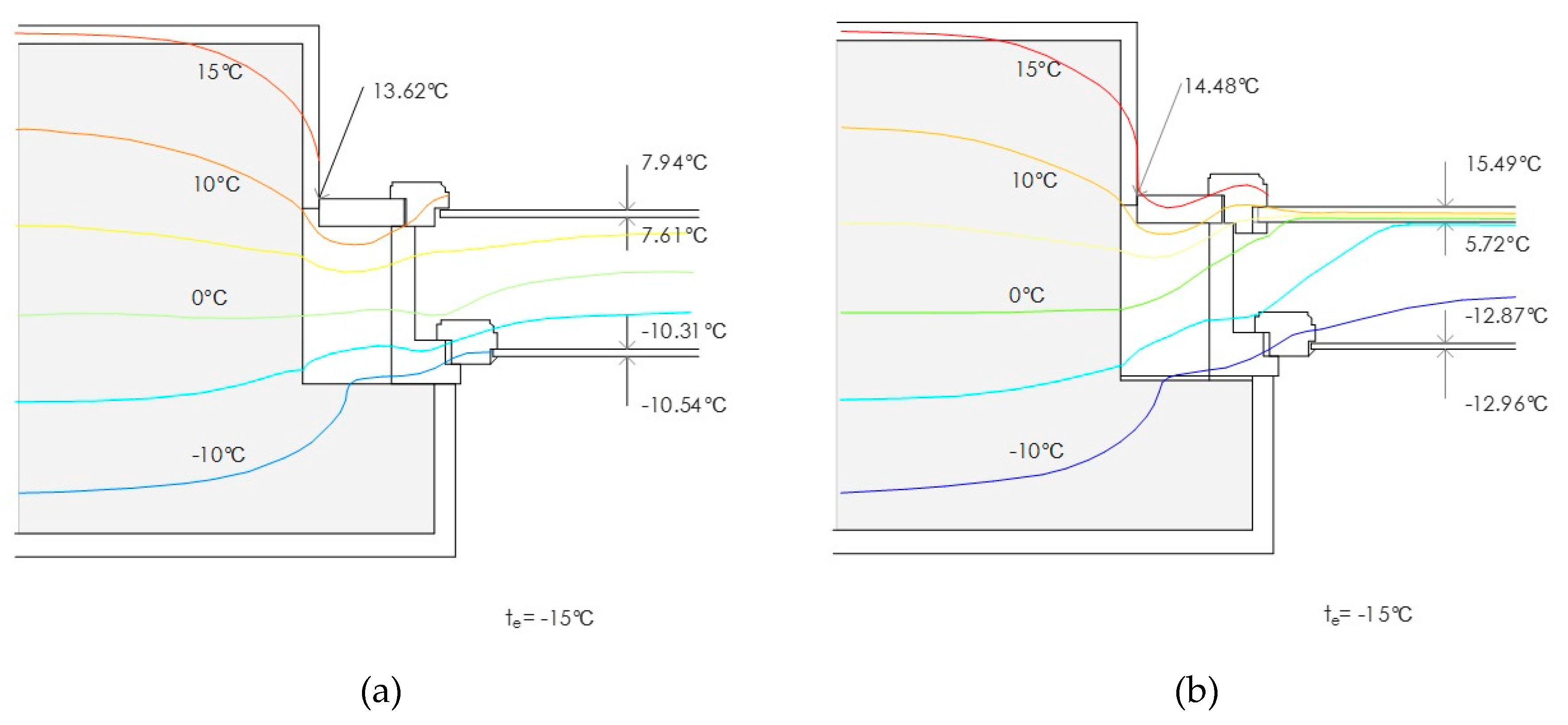
Simple replacement of the window is not possible because this design would cause deterioration of the physical conditions. Since the average thickness of a new, modern window structure with double- or triple-glazing is 80 mm compared to the wall thickness of 85 cm, the isotherms “condense” in the profile (
Figure 5).
During the heating season, when the surface temperature drops below the dew point at the connection of the wall and frame, condensation occurs, and this leads to damage. On the other hand, it does not meet the criteria of monument protection. In contrast, the box-type window structure provides a much more favorable starting point [
33]. Temperature boundary conditions of the calculation models were +20 °C indoors, −15 °C outdoors. Temperatures were calculated according to EN ISO 10077-1 standard [
34]. The mathematical-physical model was based on stationary conditions. As known that the thermal and ventilation phenomena show a time-dependent change in the reality with variable boundary conditions, these would be calculated more precisely by a dynamical simulation at a later stage of the research.
3.1. Air Permeability and Air Intake
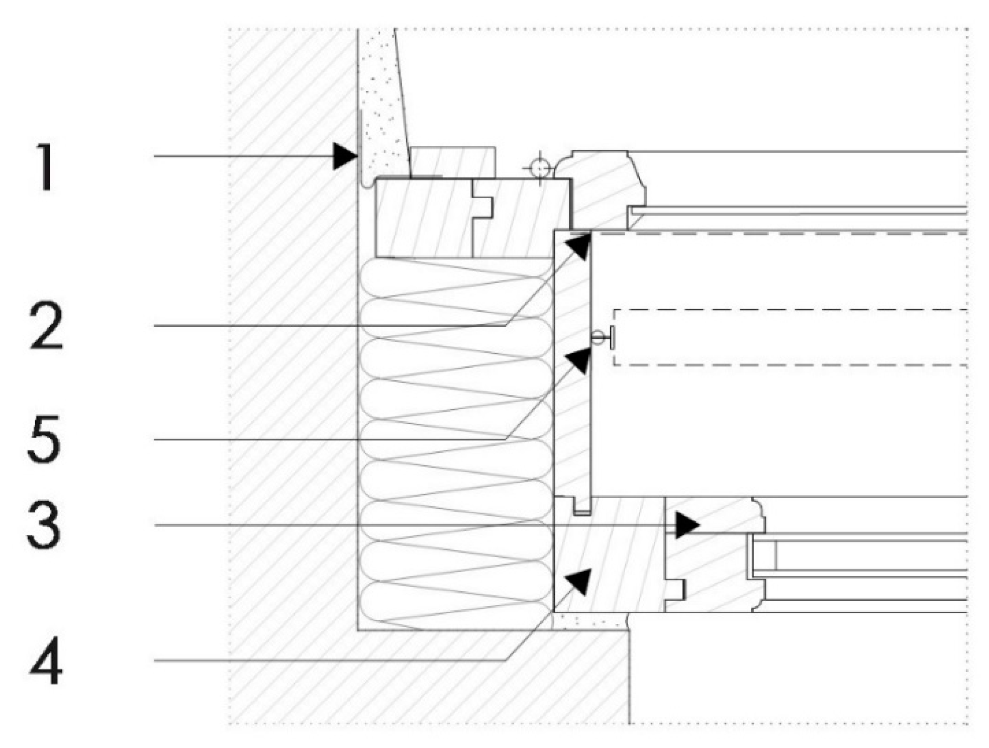
Laminar and turbulent flow is created in the opening joints in unsealed windows and due to the aging of the material. The amount of air passed is proportional to the pressure change in laminar flow and to the square root of the pressure change in turbulent flow. The length of opening joints and the permeation factor affect the amount of air passed [
35]. Thus, regarding the combined window, installation of butyl tape was designed at the connection between the casement and the masonry to prevent uncontrolled airflow. Installation details can be seen in
Figure 6.
The air-tightness of historic windows is very low, the air permeability of the grout between the frame and sash is 3.0–5.0 m
3/h m 10 dPa [
36,
37]. It is a very important aspect in the design of the box-type window to prevent condensation. This can be described by the following formula:
where ΘS
i is the internal surface temperature, Θ
i is the internal air temperature, Θ
e is the external air temperature. The requirement based on the thermal bridge catalog of the Passive House Institute is f
R,si ≥ 0.7.
3.2. Ventilation Design
The interior comfort is influenced by the design of the air inlet, the geometry of the gap, the air mass, and the air temperature. Experiments show that narrow air inlets are more efficient than wider ones [
38]. If the outside temperature is below 10 °C, the air path should be extended in the intermediate space to become warmer, or a lower rate of airflow should be introduced. If the air quality of the room deteriorates, it is necessary to increase the airflow for a short time, but the impact of draught shall be avoided.
In order for the air inlets to operate correctly, it is necessary to examine the flow processes in the intermediate space of the window. Brandl and Mach investigated the air permeability of box-type windows and box-type windows with an internal insulating glass unit and internal sealing by simulations, which were verified by laboratory measurements [
39]. The flow simulations in a box-type window showed that in each section–sloped sill, window sill, water drain drip—the flow changed, the air direction changed, and whirls were realized.
In the present case, the combined window also would be a tool for passive solar energy utilization, so the airflow must be planned. In order to keep the airflow, a sealing profile will be placed in the rebate at the connection of the sash and the casement.
The following considerations had to be taken into account when designing the room for adequate ventilation:
Provide basic ventilation independent of use, room hygiene.
Draft-free ventilation.
Low energy consumption.
Operation requiring minimal maintenance.
Integration of solar protection.
In view of the above, the position of the air inlets was designed as follows:
Fresh air inlets to be assembled on the external window frame below the middle-lower fixed pane and on both sides to direct air into the intermediate space.
From the intermediate space, warmed up fresh air is to be transported by an air inlet assembled on the upper side of the inner mullion into the interior of the building.
Spent air is to be transported into the intermediate space through air inlets on the sides in the lower fifth of the mullion, at the same height, but it will leave at the two sides of the frame on the external plane.
During summer, air inlets placed on both sides of the outer frame transport the overheated air in the intermediate space, so the air inlets on the inner side will be closed.
With a designed ventilation system, not only can ventilation losses be reduced, but also the comfort of the room can be enhanced, and protection against overheating provided. In this version, internal and external air inlet units will be Aereco-made products.
Figure 7 shows the combined window with ventilation operation.
3.3. Control System
The installed weather sensor automation system would ensure controlled ventilation, the movement of the shading structure installed between the two sashes, and the generated electricity supply into the grid. External and internal sensors are connected to the control unit.
Control sensors are:
Temperature of the air Outside (TO) in the shade.
Temperature Between Down (TBD) temperature in window in lower position.
Temperature Between Top (TBT) temperature in the window in upper position.
Temperature Inside (TI).
There will be four control units: Ventilation to Outside Down (VOD) serves as an outside air intake into intermediate space in the lower position, while the Ventilation to Outside Top (VOT) provides air outlet from the inner intermediate space to the outside in the upper position. Ventilation to Inside Top (VIT) transfers air intake from intermediate space into the interior in the upper position, and the Ventilation Outside Middle (VOM) acts as an indoor outlet to outdoor in an intermediate position, as illustrated in
Figure 8. The 16 cm wide space between the two sashes allows the installation of all these devices.
Opening and closing of the air inlets can be operated manually: Getting external air inside by VOD, VIT, VOM in an open position or VOD, VIT, VOM in an open position + ventilation, while allowing internal air out by VOD, VOT in an open position and VOM, while VIT is closed. During ventilation through filtration, all are closed. In automatic mode, the control scheme for the opening and closing of the air inlets in accordance with weather conditions is presented in
Figure 9.
The direct and indirect utilization of solar radiation, such as airflow, plays a significant role in providing the required comfort conditions; thus, the structure can operate in an ecologically energy-efficient manner.
3.4. Thermal Transmittance
According to EN ISO 10077-1 [
34], the thermal transmittance of the double glazing window can be calculated using formula:
where U
w,ext and U
w,int are the thermal transmittances of the external and internal window (W/(m
2 K)), respectively, R
se and R
si are the external and internal surface resistance of the window (m
2 K/W), respectively, and R
s is the thermal resistance of the space between the glazing (m
2 K/W).
The thermal transmittance of the external and internal window can be determined according to the standard using the formula:
where U
w,ext is the thermal transmittance of the external window (W/(m
2 K)), U
g is the thermal transmittance of the glazing (W/(m
2 K)), A
g is the glazed area (m
2), U
f is the thermal transmittance of the frame (W/(m
2 K)), A
f is the frame area (m
2), l
g is the total perimeter of the glazing (m), ψ
g is the linear thermal transmittance due to combined effect of the glazing, spacer, and frame (W/(m K)).
Determination of the thermal resistance of the air layer is in accordance with the EN ISO 6946 standard [
40]. For windows where the openings between the frame and sash are ≤ 500 mm
2 per meter of length, the value of R
s = 0.18 m
2 K/W, while for significant openings are ≥ 1500 mm
2 per meter of length, the value of R
s = 0.13 m
2 K/W must be taken into account. When the surface of openings is between 500–1500 mm
2, this case is classified as slightly ventilated by the standard, and the thermal resistance can also be determined.
Based on these values, the thermal transmittance of the selected window was calculated. In its original state: U
W = 2.430 W/(m
2 K), but with the above-mentioned reconstruction, the thermal transmittance of the combined window will be improved: U
W = 0.883 W/(m
2 K).
Figure 10 shows the heat transfer of windows regarding variations of glass replacement.
3.5. Shading
The mobile sun shading structure (
Figure 6), which is controlled by an automatic unit, but can be operated manually as well, will be built between the two window sashes (made by Krüllung) is an important component of the combined window. The textile roller blinds efficiently mitigate the heat loads realized in the inner space during the summer season up to an acceptable level, but in winter-time, they would let enough natural light into the room.
Due to monumental aspects, it is not possible to use external shading. The mobile blind placed in the intermediate space is not as effective as on the outer plane, it can only be operated in the closed state, but the structure is placed in a protected position. The solar factor for blinds to be built between the glass planes is N = 0.3 [
42].
Polycrystalline solar cell panels will be installed on both fixed sides of the external window part (made by Korax Solar). The modular size of the thin film system would allow alignment with the geometry of the window. Taking the mullions (frame dividers) of the fixed part into account, a solar panel with 0.5 m2 surface area will be mounted on the inner side of the external glass. Due to the operating requirements of the central, opening leaf–entailing the movement of the solar cells themselves would have made the design more complicated; therefore, no solar units would be mounted here. This way, the window will actually produce energy, even though the volume of the power generated by it would be a relatively small amount.
The room where the combined window would be installed is a teacher’s room, which is relatively narrow. Solar panels are regarded as permanent sunshades with respect to the inner space, moderating the light flux across the window. However, due to the dimensions of the window and the window strip under the upper part, illumination at the plane of the desk in the room will be homogeneous, and light reflected several times from the walls and the ceiling onto the working plane will also contribute to the appropriate luminous-intensity distribution of the incoming light.
4. Discussion
The façade of the BME Central building is equipped with windows with a smaller surface area on the ground floor and the top floor, but windows with the same geometry are lined up at the three intermediate levels with identical inner height. Totally, the building façades equipped represent nearly 1000 pieces of window-type covered by this article. According to the results mentioned above, the UW thermal transmittance of the combined window would be almost three times better than the value of the original one, based on which it can be stated that the entire reconstruction of windows would result in significant energy savings in the operation of the building. The advantages of the construction are not due just to heating energy reduction, but also due to the optimized ventilation, as well as passive and active shading devices, as the interior temperature is lower in the summertime. Thus, in the yearly energy balance necessity of cooling would be lower or ignorable in Budapest, as the average temperature is lower in the workrooms and classrooms; moreover, in the structure of the façade also. Similar traditional box-type windows are used in Central Europe; thus, in the same climate zones, the retrofitting results could be used mostly in the same way. In the southern, Mediterranean area the automatic operation of the ventilation and the shading would be preferable, as manual operation would not be enough to prevent summertime overheating. While in the northern part of Europe and in an oceanic climate, thermal transmittance of the traditional box-type windows should be developed with carefully checked hydrothermal properties to prevent condensation between the sashes.
After the renovation of the original window, the automated operating mode will be tested. Inner temperature, light conditions, etc., will be recorded for the purposes of evaluation and analysis at a later point in time. While the prototype window is installed, monitoring of the window element surface temperatures during testing of ventilation devices would let calculations specify performance. The design allows manual operations, such as ventilation inwards, outwards, and closing as well.
For future consideration, the window reconstruction presented above induces further development opportunities. When equipped with appropriate sealing applications, the combined window will become an acoustically high standard structure to be appropriate for areas with high levels of noise exposure. Another direction to take could be the application of smart glass or the use of blinds that can be adjusted to a different angle.
In this design, the inter-pane shading structure and the integrated solar panels would cover most of the glass surface, thus significantly reducing the risk of summer overheating while improving workplace comfort conditions. With the window reconstruction presented above, the designers aim to prove that the façades of our existing buildings can be renovated in an energy-efficient way, used for energy production, and play a role in reducing the urban heat island phenomenon.


