Article

Steel/Slag Interface Behavior under Multifunction Electromagnetic Driving in a Continuous Casting Slab Mold

1
State Key Laboratory of Advanced Special Steel, School of Materials Science and Engineering, Shanghai University, Shanghai 200444, China
2
Sino-European School of Technology, Shanghai University, Shanghai 200444, China
*
Author to whom correspondence should be addressed.
Metals 2019, 9(9), 983; https://doi.org/10.3390/met9090983
Submission received: 8 August 2019 / Revised: 29 August 2019 / Accepted: 2 September 2019 / Published: 4 September 2019

Abstract

:
The transient numerical model combined with the volume of fluid (VOF) approach is employed to investigate the steel/slag interface behavior under multifunction electromagnetic driving in a continuous casting slab mold. Here, electromagnetic stirring (EMS) and electromagnetic braking (EMBr), respectively, are chosen as flow multifunction control technologies in the upper and lower areas of the mold. The computational models are validated with measurement results. The results show that multifunction electromagnetic driving changes the flow pattern, which has the potential to simultaneously meet the requirements of the steel flow in the regions above and below the nozzle, ensuring the uniformity and activity of the molten steel in the upper region of the mold and avoiding the excessive depth of the impinging jet. After EMS, the steel forms a deflected circulation flow at the steel/slag interface, and the surface velocity distribution is more uniform. EMBr still has the function of stabilizing the meniscus when multifunction electromagnetic driving is applied. Taking wave height and wave amplitude as evaluation criteria, the influence of EMS and EMBr on the steel/slag interface can be evaluated and controlled to some extent by observing the key points.

1. Introduction

The flow behavior at the steel/slag interface is of great significance to the product quality in the slab mold [1,2,3,4]. During the continuous casting process, if the level fluctuation or surface velocity is too severe, slag entrapment or emulsification may take place, resulting in product defects [5], but too low a fluctuation near the meniscus is not conducive to the floating of inclusions and heat transfer [6]. In the actual continuous casting production, the flow of molten steel in the mold is very complex and difficult to measure, so numerical simulations are a good way to study these problems [7,8]. Anagnostopoulos and Bergeles [9] used a 3-D solution methodology to investigate the water-oil interface pattern in the mold. A volume tracking method is used to simulate wave formation and evolution in time. Hagemann et al. [10] investigated the stability of the steel/slag interface in the continuous casting process and estimated that meniscus may become unstable when the critical speed of molten steel reaches 0.5–0.8 m/s. These studies provide a basis for the development of continuous casting. Usually, in order to further attend a better product quality, steel flow control technologies including electromagnetic stirring (EMS) and electromagnetic braking (EMBr) are widely applied to continuous casting molds.
EMS uses a low-frequency traveling magnetic field to push the molten steel with the purpose of obtaining metallurgical improvements. The magnitude of the force depends on both the applied current and the effective frequency of the phase shift [11,12]. By adjusting the traveling magnetic field, it can accelerate, decelerate, or create a stirring motion. Stirring can homogenize the flow of molten steel and increase the chances of large particles floating in the mold, which reduce slab defects such as pinholes and inclusions [13,14,15,16], but with EMS it is difficult to solve the problem of jet impinging depth when a traveling magnetic field is applied to the upper part of the mold. On the other hand, EMBr restricts the steel flow through certain regions of the mold by applying a static magnetic field generated by a DC current [17,18]. The Lorentz force generated by the interaction between the magnetic field and the molten steel increases with the steel velocity, and it directly opposes the steel flow direction. Thus, the force naturally adjusts according to flow variations, making it the potential to stabilize the flow and reduce the penetration depth of inclusions [19,20]. Many studies of the effects of EMBr on the meniscus have also confirmed this point [21,22]. However, EMBr cannot effectively control and homogenize the flow of molten steel in the upper region of the mold.
The flow field and the steel/slag interface of molten steel in the mold are difficult to control precisely. Comparing with the single-circulation flow, when the flow pattern in some narrow slab mold is a double-circulation flow, the slab quality is more favorable [23]. It is difficult to simply say which flow pattern is better for different slab molds, but whether it is a double or single circulation, the theoretically certain is that steel flow in the upper area of the mold needs to have a certain activity and uniformity, and avoid the excessive depth of the impinging jet in the lower area of the mold. However, most of the previous studies focused on the obvious advantages of the traveling and static fields applied to the molten steel, and the steel flow was controlled by imposing either EMS or EMBr, but not both. In fact, recent studies have shown that the appropriate use of combined stirring and braking has the potential to optimize the flow of molten steel and to compensate for the limitations of a single electromagnetic field [24,25]. Multifunction electromagnetic driving which combines EMS and EMBr is the development trend of the current control technology of steel flow in a continuous casting mold [26,27,28,29]. However, there are few studies on the steel/slag interface behavior under multifunction electromagnetic driving. When electromagnetic driving is applied in a slab mold, the F index [30] is no longer suitable for evaluating the fluctuation of the steel/slag interface.
Thus, in the current study, a transient numerical model is developed to investigate the steel/slag interface behavior under multifunction electromagnetic driving in the slab mold. Here, EMS and EMBr are chosen as flow multifunction control technologies in the upper and lower areas of the mold, respectively. The computational models are validated with measurement results. Special attention is paid to level profile, surface velocity, wave height and wave amplitude of the steel/slag interface.

2. Mathematical Model

2.1. Basic Assumptions

The commercial software ANSYS 15.0 (ANSYS Inc., Pittsburgh, PA, USA) based on the finite volume analysis is used to simulate the molten steel flow in the slab mold. According to the actual continuous casting process, the following simplification and assumptions are made:
(1)
The fluid flow in the mold is isothermal and incompressible.
(2)
The influence of the solidified shell on the molten steel flow are neglected.
(3)
The steel in the mold is considered to be homogenous phase medium, and only the liquid slag layer is considered.
(4)
Owing to the small magnetic Reynolds number (about 0.01), the influence of molten steel flow on the magnetic fields is ignored [13].
(5)
The mold and strand are assumed to be vertical, and mold taper and oscillation are neglected.

2.2. Governing Equations

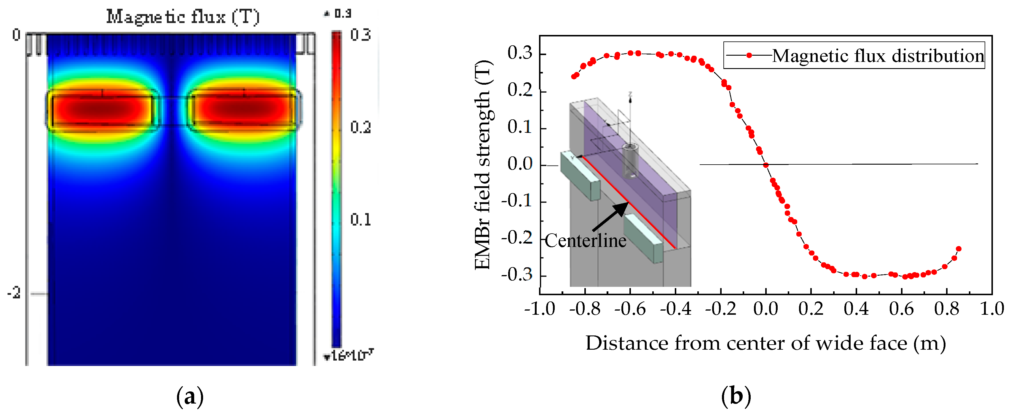
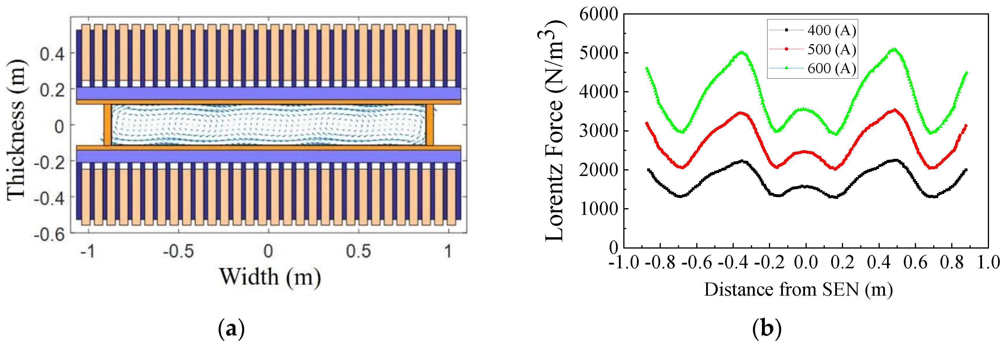
2.2.1. Electromagnetic Field Equations

Ignoring the influence of molten steel flow on electromagnetic fields, Maxwell’s equation can be expressed as follows:
· B = 0
× E = B t
× H = D t + J
J = σ E
B = μ m H
where   B is magnetic induction intensity (T), E is electric field intensity (N/C), H is magnetic field intensity (Wb/A), J is inductive current density (A/m2), D is electric displacement (C/m2), σ is electric conductivity (Ω−1), and μ m is permeability (H/m), t is the time (s).
When the flow field and electromagnetic field are coupled, the time-averaged electromagnetic force is adopted as the volume force, which can be expressed as:
F E M S = 1 2 R e ( J × B )
where F E M S is the electromagnetic stirring force (N/m3), Re represents the real part of a complex number.
According to the deduction [17], the electromagnetic braking can be expressed as:
B = B 0 + b
J = 1 μ m × B
F E M B r = J × B
where F E M B r is the electromagnetic braking force (N/m3), B 0 is an applied magnetic field (T), b is the induced magnetic field (T).

2.2.2. Flow Field Equations

ρ t + x j ( ρ U j ) = 0
t ( ρ U i ) + x j ( ρ U i U j ) = P x i + x j ( μ e f f ( U i x j + U j x i ) ) + ρ g + F i
μ e f f = μ + μ t = μ + ρ C μ k 2 ε
where ρ is the fluid density (kg/m3), U i is i -component of the fluid velocity U (m/s), x j is j spatial coordinate (m), P is pressure (Pa), F i is the electromagnetic force (N/m3), g is the gravitational acceleration (9.81 m/s2), μ e f f is the effective viscosity (kg·m−1·s−1), μ and μ t are laminar and turbulent viscosity coefficients (kg·m−1·s−1), and C u is constant (0.09).
The κ ε model [17] is used in the simulation. This model introduces the turbulence kinetic energy and the turbulence eddy dissipation to solve the effective molecular viscosity. The values of κ (m2/s3) and ε (m2/s3) come directly from differential transport equations for the turbulence kinetic energy and turbulence dissipation rate:
t ( ρ k ) + · ( ρ U j k ) = · ( ( μ + μ t σ k ) k x j ) + G ρ ε
t ( ρ ε ) + · ( ρ U j ε ) = · ( ( μ + μ t σ ε ) ε x j ) + ε k ( C ε 1 G C ε 2 ρ ε )
where C ε 1 , C ε 2 , σ ε and σ k are constants (1.44, 1.92, 1.3, 1.0), and G is turbulence production due to viscous forces which are modeled as:
G = μ t U i x j ( U i x j + U j x i )

2.2.3. VOF Model Equation

The volume of fluid (VOF) model [21] is used to track the fluctuation of the steel/slag interface, which is modeled as:
α t + · ( α U ) = 0
where   α is the molten steel volume fraction, α = 1 represents the steel, α = 0 represents the slag, and 0 < α < 1 contains the steel/slag interface. Here, α = 0.5 is chosen to represent the steel/slag interface.

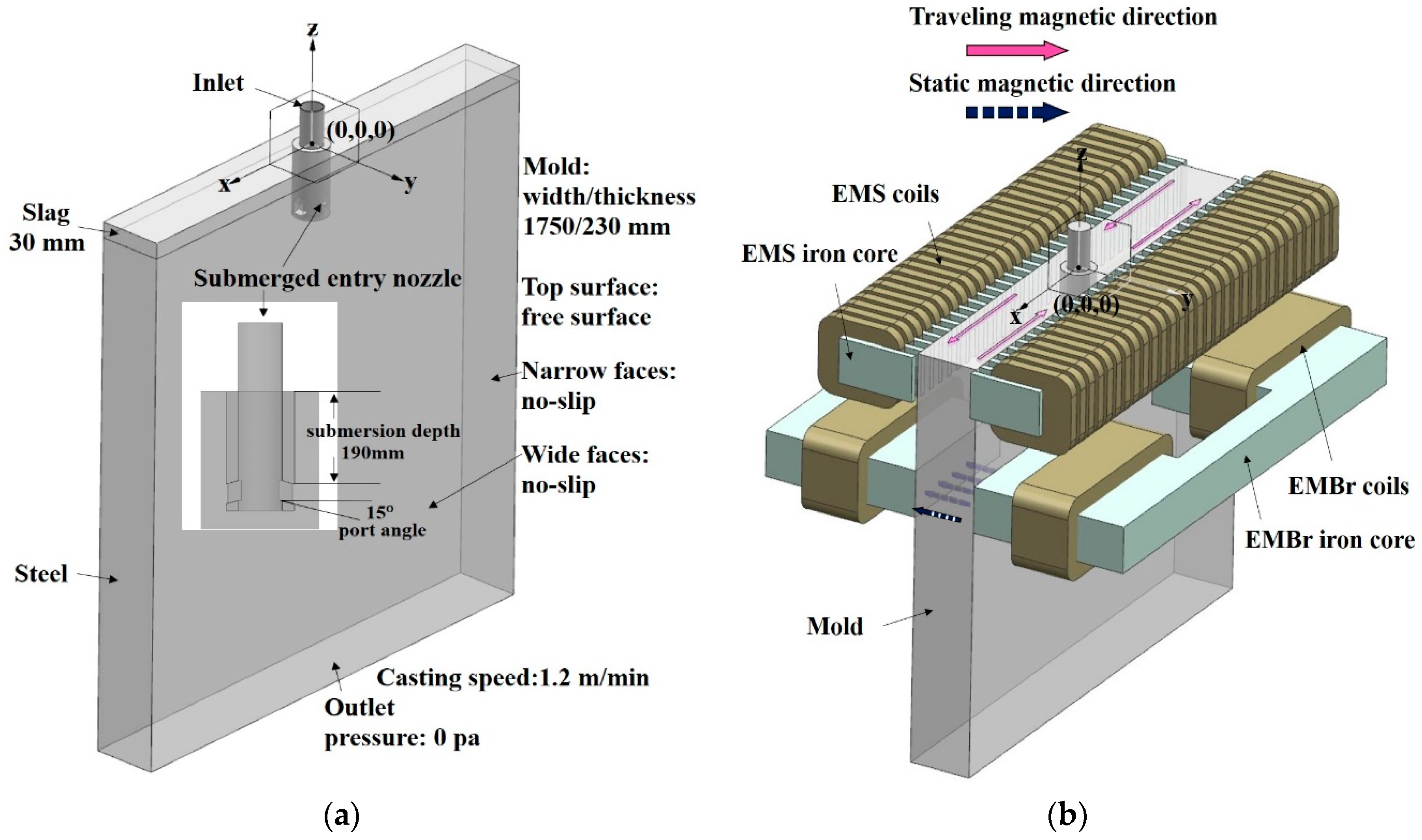
2.3. Configuration and Numerical Setup

The configuration of the continuous casting mold is sketched in Figure 1a, with the origin and the coordinates of the Cartesian system used in the simulation. The origin is located at the submerged entry nozzle (SEN) center.
Table 1 shows the dimensions of the mold configuration, in millimeters. The selection of simulation domain height (5000 mm) ensures that the flow is fully developed. The thickness of the slag layer is 30 mm. The computational grid is a full-size model, and the number of grid nodes reached 5 million. The sketch representation of the multifunction electromagnetic system is shown in Figure 1b. Respectively, EMS is located between the meniscus and the SEN outlets, passing the alternating current of 4.5 Hz, generating the traveling magnetic field, and EMBr is located below SEN outlets, which generates a static magnetic field through direct current. Furthermore, the upper surface of the EMS iron core is flush with the mold upper surface, and the upper surface of EMBr iron core is 442 mm away from the mold upper surface. Multifunction electromagnetic system is expected to have the advantages of both uniform rotational flow and weaker downward velocity with a stable meniscus flow.
The time-dependent calculations start from a previously converged steady-state solution. The final surface shape is the same, whether the calculation takes the steady simulation results as the initial conditions or the direct unsteady-state simulation calculation, but the former method can save time [9]. The conservation equations are time integrated in an implicit manner, and the time-step is 0.05. The total calculation time is 10 s. The free surface is set at the mold top, while the mold walls are assumed to be under no-slip conditions, and normal gradients of all the variables at the outlet of mold are zero [21]. The numerical simulation is performed using the commercial solver CFX 15.0 (ANSYS Inc., Pittsburgh, PA, USA). The physical parameters used in the simulation are shown in Table 1. The computational conditions shown in Table 2 are chosen in order to clarify the effects of EMS and EMBr on the steel/slag interface behavior. Here, the application intensity of EMS is characterized by ampere (A), and the application intensity of EMBr is characterized by magnetic flux (T).

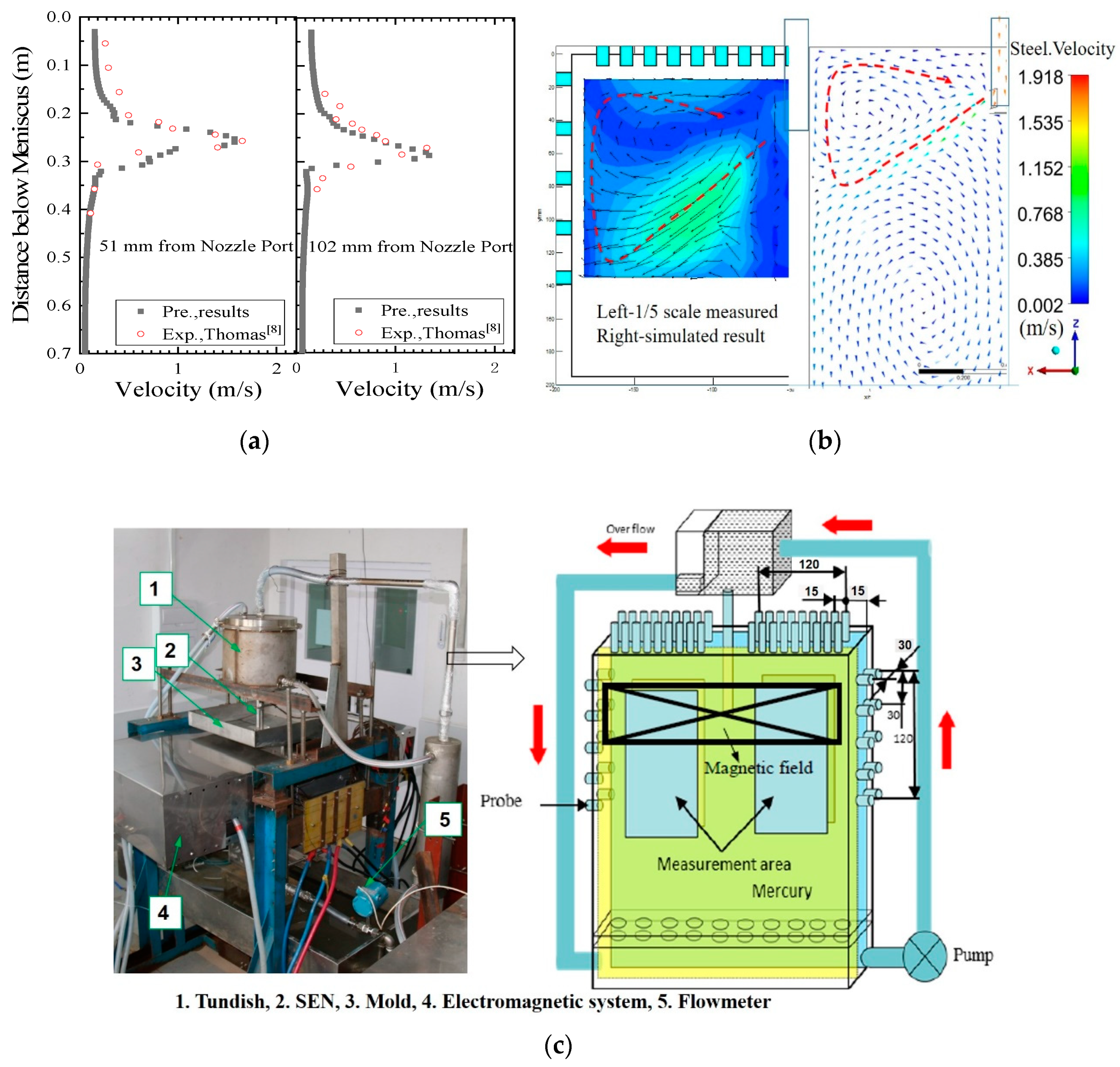
2.4. Mathematical Model Validation

In Figure 2a, the velocity profiles in the slab mold simulated by case 1 compared with Thomas’s measurements [8]. The speeds of the two positions are made along vertical centerlines at specified distances from the SEN, showing the movement of the impinging jet in the mold. The computation agrees reasonably well with the measurements. The low-melting-point metal mercury is used as the molten steel to simulate the steel flow in a 1:5-scale mold model, which is based on similar principles.
The steel velocity is measured using an Ultrasonic Doppler Velocimeter (UDV) (SIGNAL PROCESSING Inc., Lausanne, Switzerland). In Figure 2b, the steel flow in the slab mold measured by the physical experiment is compared with the case 1 simulation results. They show good agreement between the predictions and UDV measurements. More experimental details are given in previous research [29]. The physical experiment system is shown in Figure 2c.
The magnetic flux distribution in the longitudinal section at the distance of 15 mm from the core surface in the slab mold is shown in Figure 3a. The maximum value of the magnetic field strength is located at the center of the core, and away from the core, the magnetic field strength drops rapidly. In Figure 3b, the direction of magnetic field on both sides is opposite, and the maximum value can reach 0.3 T. The distribution of the static magnetic field in the mold is consistent with the model characteristics established by Cukierski and Thomas [17].
In Figure 4a, the distribution of electromagnetic forces on the horizontal section of the mold in the EMS model is shown. The direction of the tangential component of electromagnetic forces on the same side of the mold is substantially the same, and the other side is in the opposite direction. The forces exhibit the circular distribution pattern between each pair of poles on both sides of the mold. The Lorenz forces increase with the current, but the distribution is still the circular pattern. As shown in Figure 4b, overall, the Lorenz forces of the EMS increase with the current. At a distance of 15 mm from the wide face, the magnitude of the Lorentz force at different positions is different along the wide side, and peaks and valleys appear with the corresponding magnetic poles. This is consistent with the characteristics of the EMS model established by Okazawa et al. [15].

3. Results and Discussion

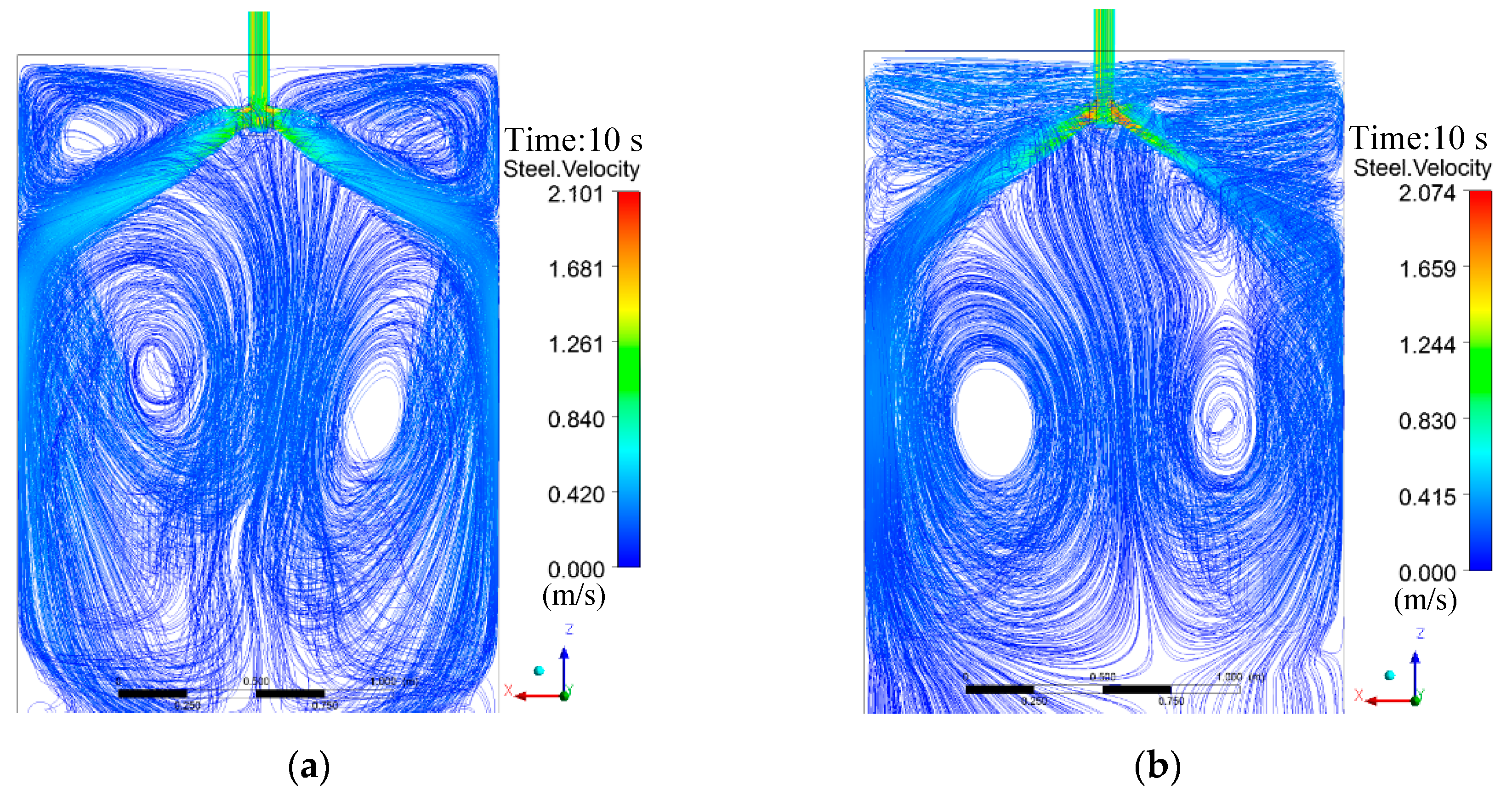
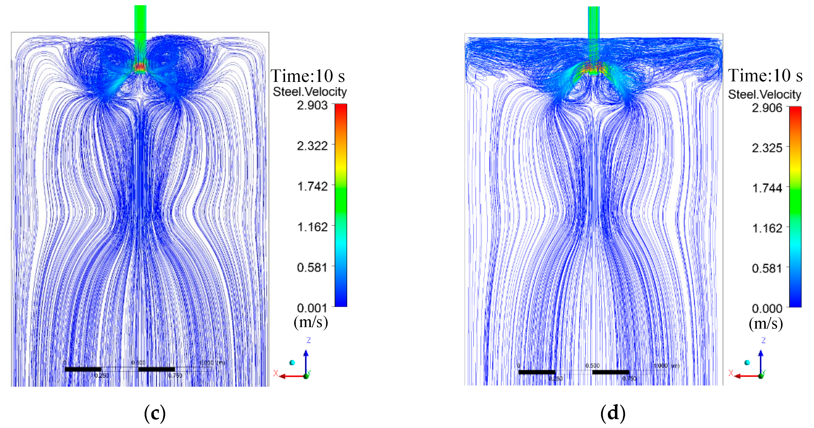
3.1. Analysis of Flow Pattern

Figure 5 shows the effect of different electromagnetic conditions on the flow patterns in the mold. In Figure 5a, the molten steel poured into the mold through the SEN and is divided into two strong impinging jets, which flow to the mold narrow-face at a certain angle and speed without applying electromagnetic driving. If the molten steel velocity leaving the SEN is high enough to strike the narrow faces, it then splits into one part forming an upward vortex and one part going downward. The upper circulation helps heat and momentum transfer to the upper part of the mold. The downward flow forms a lower circulation along the narrow side in the lower portion of the mold. It is called a double-circulations structure. When the casting conditions change, the flow pattern may change and is not easily controlled.
In Figure 5b, EMS (400 A) alone is applied to the area above the nozzle. The downward flow formed by the jet impacting the narrow side is not within the range of the traveling magnetic field, so the steel flow is hardly affected by the rotating electromagnetic forces, and the lower circulation is still maintained. The upward flow is restrained to a certain extent, and the molten steel in the traveling magnetic field is driven by electromagnetic force, forming a horizontal rotating flow in the upper part of the mold. The flow structure is called the hybrid pattern of horizontal rotating flow and lower-circulation flow. The current is increased to 500 A and 600 A respectively, and the flow behavior of molten steel in the slab mold is similar. In this flow pattern, the upper part can ensure sufficiently uniformity and activity, which is favorable for the washing effects [25], but the impinging depth of the SEN jet in the lower area is not well improved. Partially molten steel may carry non-metallic slag to a deep position and be captured by the solidified shell to form a quality defect.
In Figure 5c, EMBr (0.3 T) alone is applied to the area below the nozzle. The jet first flows to the static magnetic field at a certain velocity and interacts with it. The direction of the generated electromagnetic force is opposite to that of the SEN jet, and its magnitude is proportional to the velocity of the jet. Under the process parameters, the steel jet is blocked by the electromagnetic force before reaching the narrow mold side, and returns to the meniscus, forming a piston flow structure near the SEN. This flow pattern effectively restrains excessive impinging of the SEN jet and obtains a weak downward flow, but the molten steel flow is mainly concentrated near the SEN, which may cause uneven heat transfer, and it is not conducive to the melting of the protective slag near the narrow side in the actual production process.
In Figure 5d, the multifunctional electromagnetic drive forms a composite magnetic field in the regions above and below the nozzle. Under this electromagnetic field, the impinging jet in the slab mold is returned to the nozzle by the braking forces opposite to the direction of the SEN jet flow. And after reaching the active region of the traveling magnetic field, the molten steel is pushed by the horizontal rotating forces and restrained from the surrounding mold walls, making a strong rotational flow around the wall in the upper area of the mold. In theory, this flow pattern not only ensures that the molten steel in the upper area of the mold is active, which facilitates the uniform heat transfer and the removing of non-metallic slag, and also avoids the impact position of the steel jet too deep, which is beneficial to reduce the penetration depth of inclusions [28].

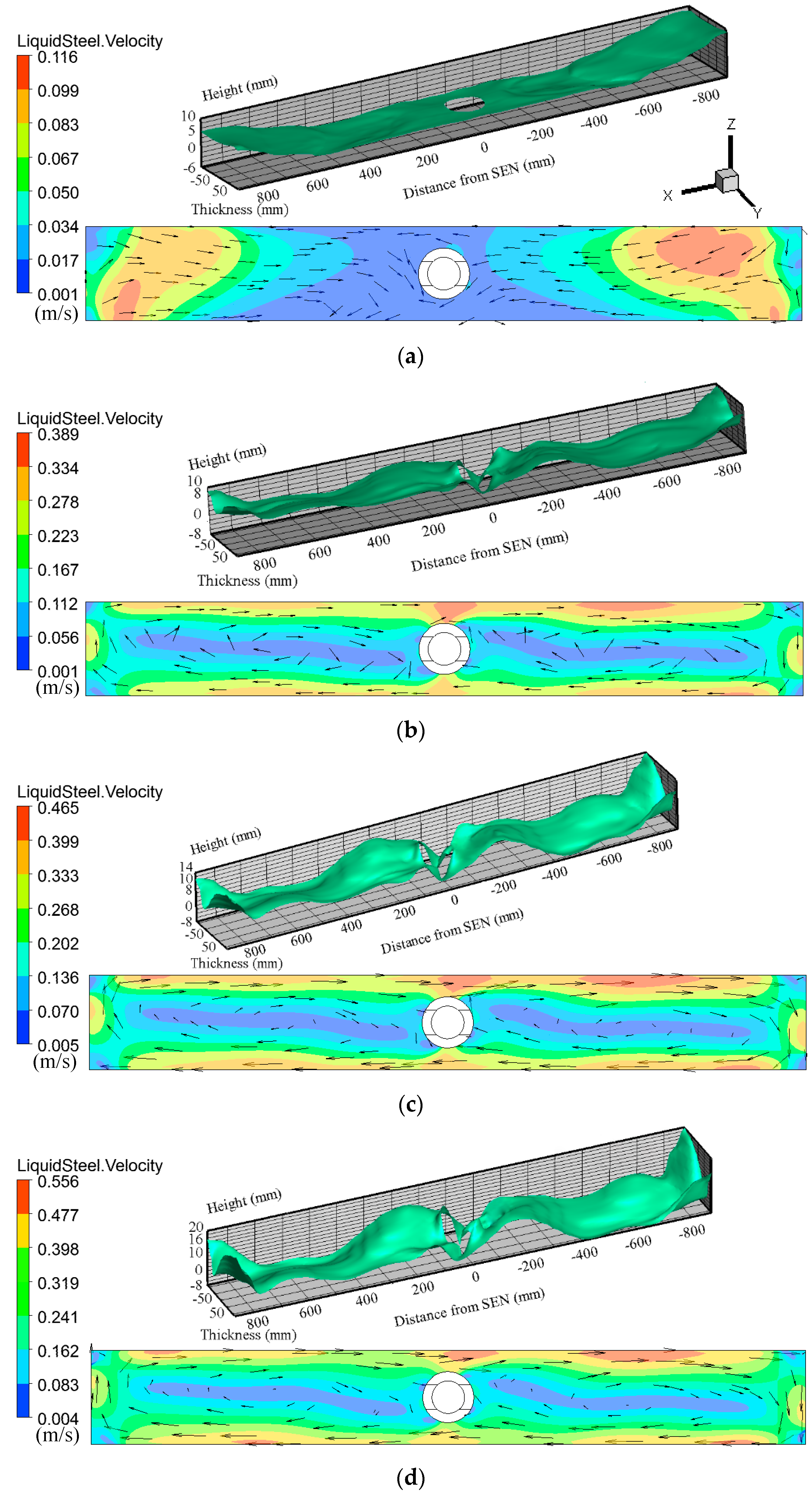
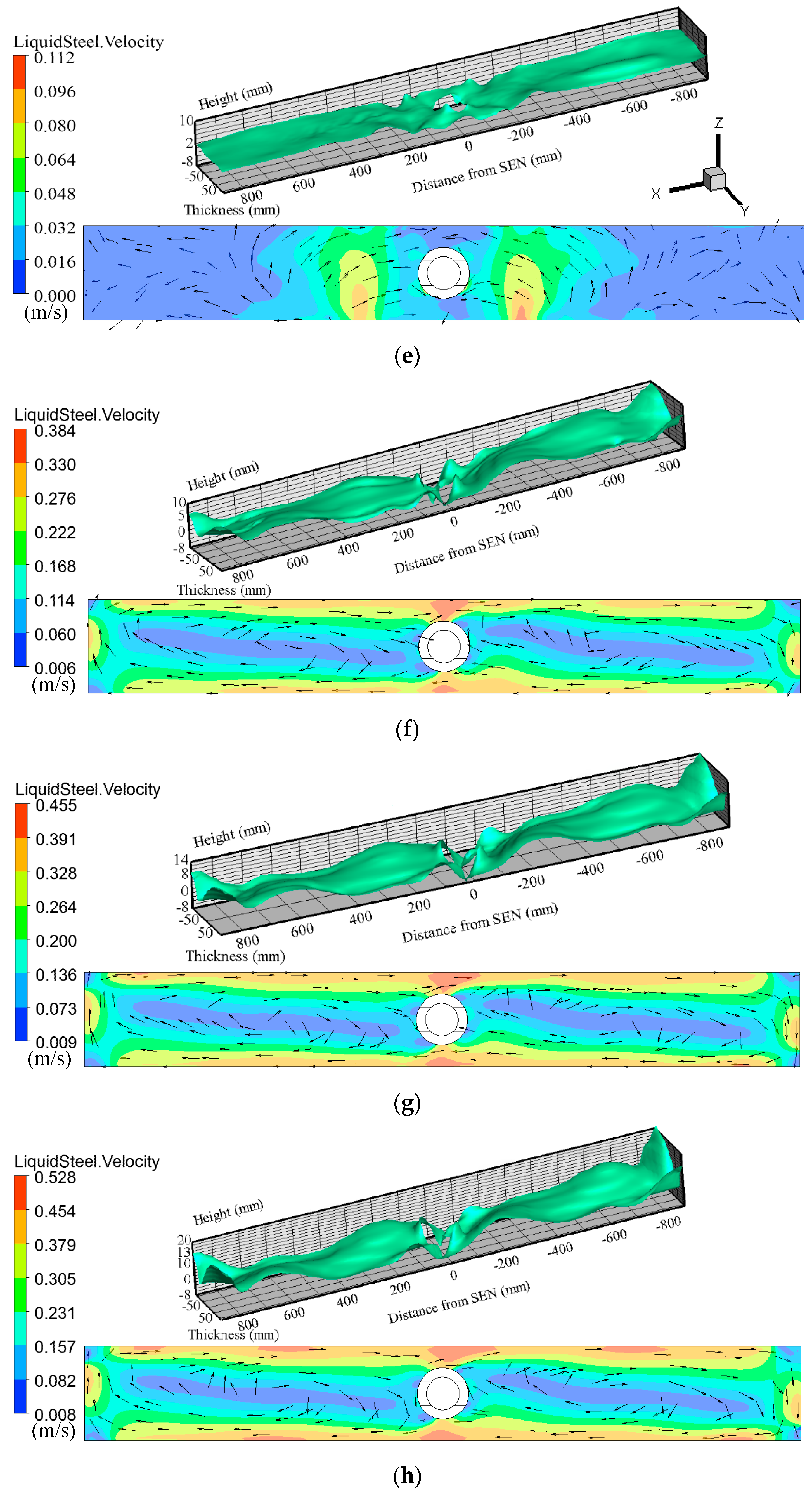
3.2. Analysis of Level Profile and Surface Velocity

In Figure 6, the upper side is level profile, and the lower side is the surface velocity of molten steel on the steel/slag interface. Observing the left side of the mold, in Figure 6a, it is obvious that the steel/slag interface near the narrow side rises to form a peak due to the impact of the upward flow. During the upward flow impact, the kinetic energy of the molten steel is gradually transformed into potential energy. When the kinetic energy is all converted into potential energy, the wave height reaches a maximum value, which can reach about 5–6 mm. In order to counteract the effect of potential energy, the molten steel flows along the surface toward the nozzle. Under the action of the shearing force, the steel/slag interface is convex downward to form a wave trough. According to the speed vector and cloud map of molten steel, the area with large surface velocities at the steel/slag interface is close to the narrow side, and the maximum surface velocity can reach 0.116 m/s, then the velocity decreases gradually during flowing to the nozzle. The molten steel on both sides of mold flows to the nozzle, part of which meets in the gap between the SEN and wide face, and part of which impacts the nozzle frontally. Under the process parameters, the upper circulation flow plays a leading role in the level profile and surface velocity, acting to transfer heat and activate the molten steel, but the impact on the steel/slag interface is too concentrated, resulting in the non-uniform flow of molten steel in the upper portion of the mold. And the location of the impinging point is close to the narrow side, which may be too much disturbance to the protective slag. Furthermore, excessive fluctuations can also break the steel/slag interface, resulting in slag entrapment.
From Figure 6b, it can be clearly seen that the upward flow is broken by the horizontal electromagnetic forces when EMS alone is applied to the upper region of the mold, which makes the molten steel rotate around the mold walls under the action of the traveling magnetic field. At this time, the level profile is dominated by the upper circulation flow and the horizontal stirring. The molten steel close to the wide faces of the mold is in a stronger magnetic field, where the electromagnetic forces are greater than that at the center, so the area with a large surface velocity is evenly distributed around the mold walls, and the maximum surface flow rate can reach 0.389 m/s. The fluctuation of the steel/slag interface near the mold walls is also relatively larger, and the maximum wave height can reach about 8 mm. Due to the centrifugal force of rotating molten steel, a certain degree of the deflected vortex is formed at the center of the steel/slag interface on one side of the mold [25]. The vortices on both sides of the mold are center-symmetric according to the SEN center because the magnitude and direction of the traveling magnetic field generated on both mold wide sides are symmetrical. The deflection of the vortex is due to the movement of molten steel along the mold wide-edges under the action of traveling magnetic field. When encountering the narrow edges of the mold, the molten steel is hindered and forced to change direction. Under the action of extrusion, a small deflection of the vortex occurs, which is also the reason for the abnormal fluctuation of the steel/slag interface at the mold corners. As shown in Figure 6c,d, when the stirring current is increased to 500 A, the fluctuation of the steel/slag interface becomes severe, and the wave height is obviously increased. The maximum wave height and surface velocity can reach about 12 mm and 0.465 m/s. The fluctuation becomes larger when the current is continuously increased to 600 A, and the maximum wave height and surface velocity are increased to about 16 mm and 0.556 m/s. The surface velocity is close to the dangerous range of 0.5–0.8 m/s [10]. Under these parameters, stirring in the upper region of the mold can avoid the impact of upper circulation on meniscus being too concentrated, and plays a very good role in activating and homogenizing the molten steel, which is conducive to uniform heat transfer and floating of inclusions as far as possible. However, if the electromagnetic stirring current is too large or the magnetic field area is too close to the steel/slag interface, it will cause excessive disturbance to the meniscus, which may even break the steel/slag interface, resulting in the entrainment of powder. Therefore, the appropriate stirring position and stirring current are very crucial.
Figure 6e clearly shows that after applying EMBr alone to the lower region of the mold, the disturbed area on the steel/slag interface mainly concentrates near the nozzle, which is also the area with high surface velocities, because the steel jet is restrained and forms a piston flow pattern near the SEN. The maximum velocity can reach 0.112 m/s, which is slightly lower than that of 0.116 m/s without electromagnetic fields, and the maximum wave height can be reduced to about 2 mm. This is consistent with the simulation results of Cukierski and Thomas [17] that EMBr can stabilize the meniscus. Obviously, the impingement depth of SEN jet is effectively suppressed by the static magnetic field, but surface velocity provides weak washing effects.
In Figure 6f, when multifunction electromagnetic driving acts, the flow behavior of molten steel in the mold is dominated by the SEN jet, electromagnetic stirring, and electromagnetic braking. The SEN jet is inhibited by the static magnetic field, which offsets part of the steel gravity, making the jet can′t directly impinge the narrow face. The impinging depth becomes smaller and carries part of the steel and energy moving upwards. In the upper region of the mold, the molten steel flows relatively uniformly around the wall. When the stirring current is 400 A and the magnetic flux of EMBr is 0.3 T, the maximum fluctuation is close to 5-6 mm and the maximum flow rate is 0.384 m/s. Increasing the stirring current, the behavior of the steel/slag interface is similar. When increasing to 500 A, the maximum fluctuation and surface velocity are about 10 mm and 0.455 m/s. When increasing to 600 A, the maximum wave height and surface velocity are about 14 mm and 0.528 m/s. The level profiles of the steel/slag interface under multifunction electromagnetic driving are similar that under EMS only, but maximum surface velocity and wave height decrease. Therefore, when EMS and EMBr are applied simultaneously, EMBr can reduce the impact depth of the jet and make up for the limitation of EMS for the lower SEN jet, and still have a certain stabilizing effect on the steel/slag interface. While EMS is used to homogenize and activate the molten steel, it can also make up for the defects of the non-uniform flow of molten steel when EMBr alone is applied. That is to say, when the parameters of electromagnetic stirring and braking are appropriate, to a certain extent, multifunction electromagnetic driving can meet the requirements of molten steel in the upper and lower regions of mold simultaneously, which is helpful to better control and optimize the flow of molten steel in the slab mold.

3.3. Analysis of Level Fluctuation

In order to further observe the behavior of the steel/slag interface, the level fluctuation is monitored by several key points in the slab mold. The selected positions along the mold wide-direction are based on the near narrow side (x = 0.85 m, the action area of upper circulation), the near center (x = 0.65 m, the influence area of vortex) and the near SEN (x = 0.25 m, the influence area of EMBr). Three points are selected in the y-direction of each region, including the center (y = 0) and two points near the wide edge (y = ±0.1 m).
The average wave height ( h ) and wave amplitude ( h R M S ) are used to characterize level fluctuation. Here, the wave height is the average position deviating from the initial interface, and the wave amplitude is the root mean square (RMS) of the wave height, which can be calculated according to the Equations (17) and (18), where h 0 is the initial position and n is 200:
h = 1 n i = 1 n ( h i h 0 )
h R M S = 1 n i = 1 n ( h i h ) 2
In Figure 7a, the point (x = 0.85, y = 0) is close to the narrow face. The steel/slag interface near the narrow side shows a peak without electromagnetic driving. When the stirring current is 400 A, the effect of the upper circulation is weakened partly and the wave height is reduced. With the increase of stirring current, the action of EMS becomes stronger. After reaching a critical value, the wave height is mainly dominated by EMS, and then the wave height increases again. Appling EMS alone, the fluctuations at two points close to the wide sides (x = 0.85, y = ±0.1) did not decrease first and then increase, and the wave heights are higher than that at the center which may be due to the accumulation of the steel at the mold corners and the rotational flow of the steel along the mold walls. There may be a small central region near the narrow side where the dominant role of EMS and upper circulation can be determined by a critical current value. When only EMBr is applied, the SEN jet is restrained and the fluctuation near the narrow side is reduced. And the wave heights at three points in the y-direction are similar. When multifunction electromagnetic driving is applied, the wave height is mainly affected by EMS and increases with stirring current. Compared with the wave amplitude of the narrow side under different electromagnetic conditions, the amplitude does not change much, and decreases slightly, which shows that EMS does not increase the amplitude and EMBr still has the function of stabilizing the steel/slag interface. So, feature points can be selected to detect and judge the influence of electromagnetic driving on the steel/slag interface near the narrow side.
In Figure 7b, the point (x = 0.65, y = 0) is close to the center of the left side. When the stirring current is 0 A, the potential energy of the peak at the narrow side position is not completely offset, where the steel/slag interface is close to the initial interface. With 400 A of stirring current, a horizontal circulation flow is formed at the steel/slag interface, and then a vortex is formed at the center of the circulation, so the wave height decreases. As the stirring current increases, the rotational speed of molten steel increases, and the vortex becomes more obvious. The steel/slag interface here decreases slightly and forms a trough, which accords with the characteristics of the vortex center. When EMBr alone is applied, the SEN jet is forced to change its direction and impact the steel/slag interface, showing a wave crest.
When multifunction electromagnetic driving is applied, EMBr counteracts the vortex, transforming the trough into a peak, and the wave height increases with stirring current. The two points close to the wide mold faces (x = 0.65, y = ±0.1) have opposite wave patterns that one side shows the trough, and the other side is the peak. This may be due to the opposite direction of electromagnetic force on both wide sides, resulting in different effects on the SEN jet, so the steel/slag interface behavior is opposite after applying EMS. During the whole process of electromagnetic conditions change, the wave amplitude changes in the range of 1 mm, and the amplitude decreases slightly after applying EMBr. To a certain extent, key points can be selected in the central area of one mold side to predict the influence of the central vortex and prevent slag entrainment caused by the eddy.
As shown in Figure 7c, the point (x = 0.25, y = 0) is close to the nozzle. When the stirring current is 0 A, the steel/slag interface is in a trough state. With the application of EMS, the trough transforms into a wave peak and the wave height increases with the stirring current. When only EMBr is applied, the area near the nozzle is affected, making the position of steel/slag interface closer to the initial interface than without electromagnetic driving. After applying multifunction electromagnetic driving, the trough gradually changes into a peak with the increase of stirring current. Similar to Figure 7b, the fluctuation rule of two points (x = 0.25, y = ±0.1) near the wide faces in the y-direction is the opposite. The wave amplitude increases slightly after the application of EMBr because the jet is suppressed and the level fluctuation near the nozzle is subjected to an upward impact. Selecting key points near the nozzle can predict the action of EMBr, in order to optimize the electromagnetic parameters. After the application of electromagnetic technology, the F value [30] is not suitable for predicting interface behavior. Taking wave height and wave amplitude as evaluation criteria, key points have potential to predict the effect of electromagnetic stirring and braking on the steel/slag interface behaviors, which can provide some references for the application of electromagnetic driving in a continuous casting mold.

4. Conclusions

In this work, a transient numerical model combined with the volume of fluid (VOF) approach is employed to study the effect of multifunction electromagnetic driving on the steel/slag interface behavior. Based on the obtained results, the following conclusions are drawn:
(1)
Multifunction electromagnetic driving that combines electromagnetic stirring (EMS) and electromagnetic braking (EMBr) changes the flow pattern, which has the potential to simultaneously meet the requirements of the steel flow in the regions above and below the nozzle, ensuring the uniformity and activity of the molten steel in the upper region of the mold and reducing the penetration depth of inclusions.
(2)
EMS can change the level profile and form a deflective circulation at the steel/slag interface. After EMS, the distribution of surface velocity is more uniform. The surface velocity increases with stirring current. The fluctuation shapes of the steel/slag interface under multifunction electromagnetic driving are similar that when only EMS is applied, but the metallurgical action of EMBr on stabilizing steel/slag interface is still retained.
(3)
Taking wave height and wave amplitude as evaluation criteria, key points can be selected to predict the effect of EMS and EMBr on the steel/slag interface behavior, which has potential to provide some reference for online real-time control and optimization of the steel/slag interface behavior under electromagnetic driving.

Author Contributions

X.S. developed the model, analyzed data and wrote the paper; Z.L., B.L. and H.L. provided suggestions on modeling and polished the English language for this work; Y.Z. and Z.R. gave suggestions on the structures of this work.

Funding

This work is financially supported by the National Natural Science Foundation of China (Grant No. U1860107 and U1738105).

Conflicts of Interest

The authors declare no conflict of interest.

References

  1. Saldana-Salas, F.; Torres-Alonso, E.; Ramos-Banderas, J.; Solorio-Díaz, G.; Hernández-Bocanegra, C. Analysis of the Depth of Immersion of the Submerged Entry Nozzle on the Oscillations of the Meniscus in a Continuous Casting Mold. Metals 2019, 9, 596. [Google Scholar] [CrossRef]
  2. Deng, A.Y.; Xu, L.; Wang, E.G.; He, J.C. Numerical Analysis of Fluctuation Behavior of Steel/Slag Interface in Continuous Casting Mold with Static Magnetic Field. J. Iron Steel Res. Int. 2014, 21, 809–816. [Google Scholar] [CrossRef]
  3. Yu, H.Q.; Zhu, M.Y.; Wang, J. Interfacial Fluctuation Behavior of Steel/Slag in Medium-Thin Slab Continuous Casting Mold with Argon Gas Injection. J. Iron Steel Res. Int. 2010, 17, 5–11. [Google Scholar] [CrossRef]
  4. Shen, B.Z.; Shen, H.F.; Liu, B.C. Instability of fluid flow and level fluctuation in continuous thin slab casting mould. ISIJ Int. 2007, 47, 427–432. [Google Scholar] [CrossRef]
  5. Thomas, B.G. Review on Modeling and Simulation of Continuous Casting. Steel Res. Int. 2018, 89, 21. [Google Scholar] [CrossRef]
  6. Li, X.; Li, B.; Liu, Z.; Niu, R.; Liu, Y.; Zhao, C.; Huang, C.; Qiao, H.; Yuan, T. Large Eddy Simulation of Multi-Phase Flow and Slag Entrapment in a Continuous Casting Mold. Metals 2019, 9, 7. [Google Scholar] [CrossRef]
  7. Vynnycky, M. Applied Mathematical Modelling of Continuous Casting Processes: A Rev. Metals 2018, 8, 928. [Google Scholar] [CrossRef]
  8. Thomas, B.G.; Huang, X.; Sussman, R.C. Simulation of Argon Gas Flow Effects in a Continuous Slab Caster. Metall. Mater. Trans. B 1994, 25, 527–547. [Google Scholar] [CrossRef]
  9. Anagnostopoulos, J.; Bergeles, G. Three-dimensional modeling of the flow and the interface surface in a continuous casting mold model. Metall. Mater. Trans. B 1999, 30, 1095–1105. [Google Scholar] [CrossRef]
  10. Hagemann, R.; Schwarze, R.; Heller, H.P.; Scheller, P.R. Model Investigations on the Stability of the Steel-Slag Interface in Continuous Casting Process. Metall. Mater. Trans. B 2013, 44, 80–90. [Google Scholar] [CrossRef]
  11. Kunstreich, S. Electromagnetic stirring for continuous casting. Rev. Metall. 2003, 100, 395–408. [Google Scholar] [CrossRef]
  12. Kubota, J.; Kubo, N.; Ishii, T.; Suzuki, M.; Aramaki, N.; Nishimachi, R. Steel flow control in continuous slab caster mold by traveling magnetic field. NKK Tech. Rev. 2001, 85, 1–9. [Google Scholar]
  13. Zhang, W.; Luo, S.; Chen, Y.; Wang, W.; Zhu, M. Numerical Simulation of Fluid Flow, Heat Transfer, Species Transfer, and Solidification in Billet Continuous Casting Mold with M-EMS. Metals 2019, 9, 66. [Google Scholar] [CrossRef]
  14. Thomas, B.; Cho, S. Overview of Electromagnetic Forces to Control Flow During Continuous Casting of Steel. IOP Conf. Ser. Mater. Sci. Eng. 2018, 424, 012027. [Google Scholar] [CrossRef]
  15. Okazawa, K.; Toh, T.; Fukuda, J.; Kawase, T.; Toki, M. Fluid flow in a continuous casting mold driven by linear induction motors. ISIJ Int. 2001, 41, 851–858. [Google Scholar] [CrossRef]
  16. Kubota, J.; Kubo, N.; Suzuki, M.; Ishii, T.; Nishimachi, R.; Aramaki, N. Steel flow control with traveling magnetic field for slab continuous caster mold. Tetsu-to-hagane 2000, 86, 271–277. [Google Scholar] [CrossRef]
  17. Cukierski, K.; Thomas, B.G. Flow Control with Local Electromagnetic Braking in Continuous Casting of Steel Slabs. Metall. Mater. Trans. B 2007, 39, 94–107. [Google Scholar] [CrossRef]
  18. Timmel, K.; Eckert, S.; Gerbeth, G. Experimental Investigation of the Flow in a Continuous Casting Mold under the Influence of a Transverse, Direct Current Magnetic Field. Metall. Mater. Trans. B 2011, 42, 68–80. [Google Scholar] [CrossRef]
  19. Liu, Z.; Vakhrushev, A.; Wu, M.; Karimi-Sibaki, E.; Kharicha, A.; Ludwig, A.; Li, B. Effect of an Electrically-Conducting Wall on Transient Magnetohydrodynamic Flow in a Continuous Casting Mold with an Electromagnetic Brake. Metals 2018, 8, 609. [Google Scholar] [CrossRef]
  20. Miao, X.; Timmel, K.; Lucas, D.; Ren, Z.; Eckert, S.; Gerbeth, G. Effect of an Electromagnetic Brake on the Turbulent Melt Flow in a Continuous Casting Mold. Metall. Mater. Trans. B 2012, 43, 954–972. [Google Scholar] [CrossRef]
  21. Li, Z.; Wang, E.; Zhang, L.; Xu, Y.; Deng, A. Influence of Vertical Electromagnetic Brake on the Steel/Slag Interface Behavior in a Slab Mold. Metall. Mater. Trans. B 2017, 48, 2389–2402. [Google Scholar] [CrossRef]
  22. Takatani, K. Effects of electromagnetic brake and meniscus electromagnetic stirrer on transient molten steel flow at meniscus in a continuous casting mold. ISIJ Int. 2003, 43, 915–922. [Google Scholar] [CrossRef]
  23. Kunstreich, S.; Dauby, P.H. Effect of molten steel flow pattern on slab quality and the need for dynamic electromagnetic control in the mould. Ironmak. Steelmak. 2005, 32, 80–86. [Google Scholar] [CrossRef]
  24. Yang, H.; Tehranchi, F.; Eriksson, J.-E.; Song, J. Water Modeling of Stirring and Braking Processes in a Slab Caster Mold. In Proceedings of the AISTech 2010, Pittsburgh, PA, USA, 3–6 May 2010; pp. 135–146. [Google Scholar]
  25. Han, S.-W.; Cho, H.-J.; Jin, S.-Y.; Sedén, M.; Lee, I.-B.; Sohn, I. Effects of Simultaneous Static and Traveling Magnetic Fields on the Molten Steel Flow in a Continuous Casting Mold. Metall. Mater. Trans. B 2018, 49, 2757–2769. [Google Scholar] [CrossRef]
  26. Okada, N.; Kawamoto, M.; Ohga, S. Development of EMBr/EMS Multifunction Mold. IOP Conf. Ser. Mater. Sci. Eng. 2018, 424, 012031. [Google Scholar] [CrossRef]
  27. Yang, H.; Seden, M.; Jacobson, N.; Eriksson, J.-E.; Hackl, H. Development of the Third-Generation FC Mold by Numerical and Water Model Simulations. In Proceedings of the AISTech 2012, Atlanta, GA, USA, 7–9 May 2012. [Google Scholar]
  28. Cho, S.-M.; Thomas, B.G. Electromagnetic Forces in Continuous Casting of Steel Slabs. Metals 2019, 9, 471. [Google Scholar] [CrossRef]
  29. Li, B.; Lu, H.B.; Shen, Z.; Sun, X.H.; Zhong, Y.B.; Ren, Z.M.; Lei, Z.S. Physical Modeling of Asymmetrical Flow in Slab Continuous Casting Mold due to Submerged Entry Nozzle Clogging with the Effect of Electromagnetic Stirring. ISIJ Int. 2019. accepted. [Google Scholar]
  30. Teshima, T.; Kubota, J.; Suzuki, M.; Ozawa, K.; Masaoka, T.; Miyahara, S. Influence of casting conditions on molten steel flow in continuous casting mold at high speed casting of slabs. Tetsu-to-hagane 1993, 79, 576–582. [Google Scholar] [CrossRef]
Figure 1. Schematics of the numerical model: (a) slab mold; (b) electromagnetic devices.
Metals 09 00983 g001
Figure 2. (a) Comparison of velocity profiles along two vertical lines at different distances from the submerged entry nozzle (SEN); (b) Comparison of molten steel velocity measured by physical experiment with that measured by simulation case 1; (c) Physical experiment system.
Metals 09 00983 g002
Figure 3. Electromagnetic braking (EMBr) field strength profiles for setting 0.3 T in the slab mold. (a) Magnetic flux distribution in the longitudinal section; (b) Magnetic field strength profiles along a wide-face centerline.
Metals 09 00983 g003
Figure 4. (a) Distribution of Lorenz forces on the horizontal cross-section at the central level of electromagnetic stirring (EMS). (b) Distribution of Lorenz forces along the wide face of the mold at different currents.
Metals 09 00983 g004
Figure 5. Comparison of steel flow patterns in the slab mold with different electromagnetic conditions: (a) without electromagnetic driving; (b) with EMS; (c) with EMBr; (d) with multifunction electromagnetic driving.
Metals 09 00983 g005aMetals 09 00983 g005b
Figure 6. Level profile and surface velocity in the slab mold under different electromagnetic conditions. Time: 10 s; (a) 0 A; (b) 400 A; (c) 500 A; (d) 600 A; (e) 0 A + 0.3 T; (f) 400 A + 0.3 T; (g) 500 A + 0.3 T; (h) 600 A + 0.3 T.
Metals 09 00983 g006aMetals 09 00983 g006b
Figure 7. Level fluctuation of the steel/slag interface driven by different electromagnetic conditions. (a) x = 0.85 m; (b) x = 0.65 m; (c) x = 0.25 m.
Metals 09 00983 g007aMetals 09 00983 g007b
Table 1. The process parameters and physical properties of steel and slag.
Process ParametersPhysical Properties
Mold width/thickness (mm)1750/230Steel density (kg/m3)7020
domain height (mm)5000Slag density (kg/m3)2700
SEN inner/outer diameter (mm)80/125Steel dynamic viscosity kg/(m∙s)0.005
SEN port width/height (mm)60/80Slag dynamic viscosity kg/(m∙s)0.09315
SEN submerged depth (mm)190Steel electrical conductivity (S/m)7.14 × 105
SEN port angle (mm)15°Slag electrical conductivity (S/m)2 × 10−5
Inlet velocity (m/s)1.6Surface tension (N/m)1.6
AC frequency (Hz)4.5--
Slag layer thickness (mm)30--
Table 2. List of the simulated cases.
Case NumberCasting Speed (m/min)Immersion Depth (mm)EMS (A)EMBr (T)
11.219000
21.21904000
31.21905000
41.21906000
51.219000.3
61.21904000.3
71.21905000.3
81.21906000.3

