1. Introduction
The weight reduction of automotive components, as is well-known, is one of the most feasible measures for reducing vehicle emissions [
1,
2,
3,
4,
5]. It is commonly applied in the production of new cars and high-performance vehicles, although it has only recently been approached for heavier means of transport [
6,
7]. The difficulty arising from the substitution of traditional metals (i.e., steel, cast iron) with lighter ones (i.e., aluminium alloys) in this class of vehicles is related both to the elevated operating loads, which imposes strict requirements on resistance and stiffness, and to the lower eligible costs. Of course, the preservation of the safety and performance levels required by automotive standards is a very important aspect [
8,
9] that needs to be carefully evaluated when reducing component weights. This is particularly true for safety-critical parts such as the suspension cross beam, control arms, and brakes, failures in which result immediately in the loss of vehicle orientation [
10]. Starting from this definition, it is clear that the structural resistance of these products is a very relevant and challenging task. Therefore, their development and validation process comprises different forms of analysis, considering the several factors affecting the mechanical behaviour (i.e., the design, material, production technology, process parameters, etc.), the results of which lead to the final determination of the component features. Firstly, Finite Element Analysis (FEA) is a fundamental tool in the evaluation of structural performance, and is used in order to drive the design to more mature levels prior to the availability of a prototype [
11]. The main advantages of the preliminary optimization of a design include: saving the cost of physical prototyping at an inappropriate point in time, lowering the development time and the time to market, and further reducing the component weight thanks to geometrical optimization. The potential risks and failure modes can be predicted and prevented much earlier in the development stage thanks to virtual analysis [
11]. Similarly, when working on new applications, it may be necessary for some laboratory tests (e.g., tensile tests, corrosion analysis, microstructural investigation, etc.) to preliminarily evaluate some sample properties far ahead of a prototype’s availability, and to consequently set the features of the components [
7]. These tests could be also useful for improving the precision of the FEA model through the implementation of more detailed properties related to the case studied. Once the design and properties of the components have been defined, prototypes can be subsequently be produced and validated.
Physical durability tests for validation purposes are usually carried out on protypes at later stages of the development process. The final aim of such testing is to confirm that the physical components meet the expected mechanical resistance suggested by the initial numerical computer simulations [
12]. Indeed, for many safety-critical issues, physical testing remains indispensable. Field testing is the most natural durability assessment procedure for demonstrating the reliability of a vehicle with respect to chassis and suspension endurance. This consists of driving along a predefined path that reflects different public road conditions (e.g., highway, urban, hill). However, vehicle road tests are very time consuming, expensive, generally difficult to reproduce, and are usually impossible to carry out in the early development stages [
13,
14,
15,
16]. A widely employed option for accelerating the process of durability analysis is indoor testing trough test rigs that have been designed for this purpose. In addition to the reduction in testing time, there are other benefits, including no full vehicle prototype being required for the validation of the component or subsystem, while the tests are simultaneously more readily reproducible, and the experiments can be much more easily observed [
13].
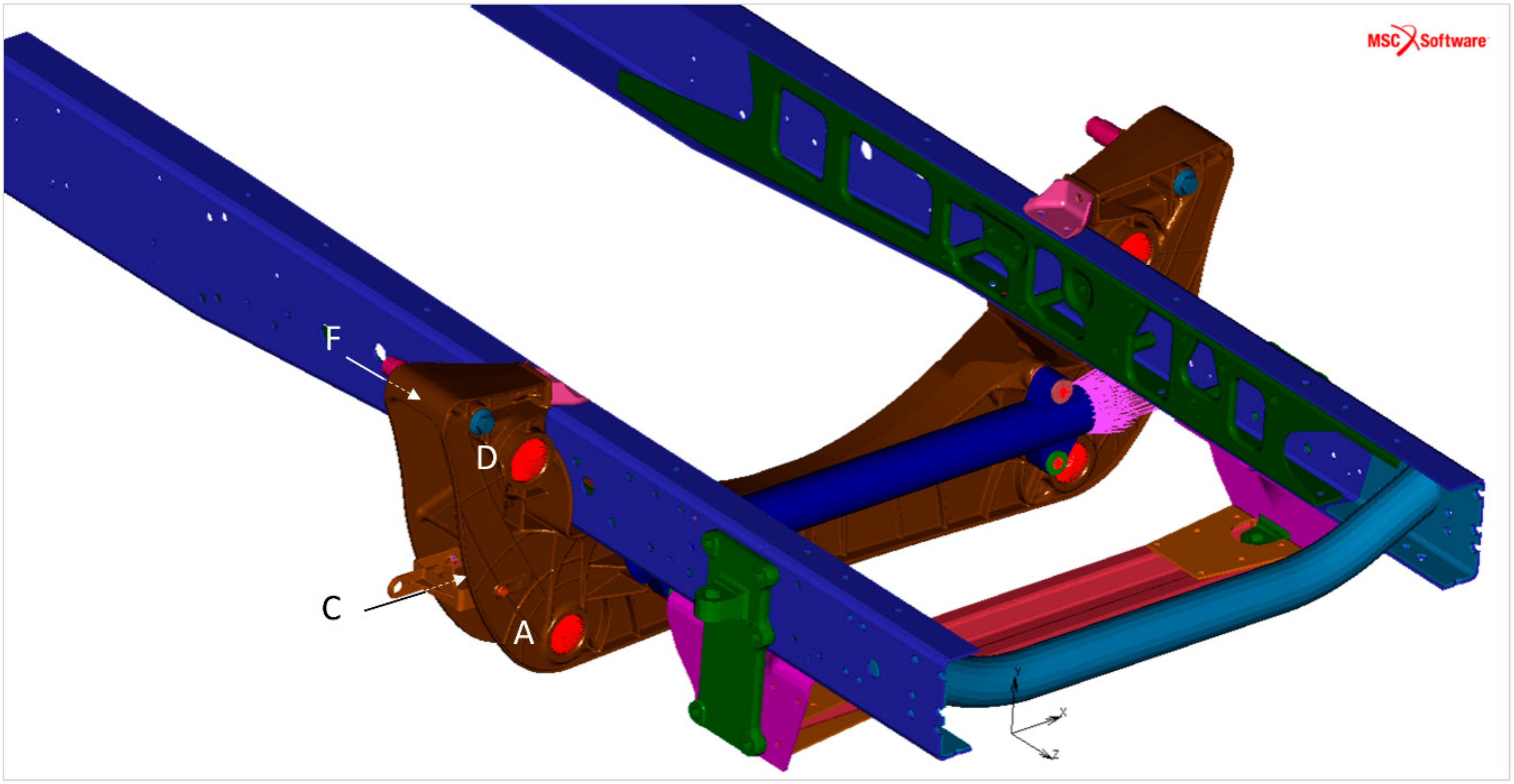
In the particular case of suspensions, tests are usually performed on specially designed benches employed to investigate the fatigue behaviour of axle systems under various driving and road conditions. These tests are carried out with equivalent loads. Specifically, mission profiles consist of several loading events that are representative of service loads generated during vehicle circulation. The real loads (forces and moments) transmitted to the wheel during the vehicle mission are measured with Wheel Force Transducers (WFT) and elaborated into reduced time histories. During road simulator testing, these time histories are applied to systems by means of movements on the wheels while the axle is attached to fixed blocks [
7]. Road simulator test rigs are commonly used for subsystems of different sizes [
13].
Specific loading conditions are sometimes not suitable for testing by means of a road simulator test bench. This could be attributable to either the difficulty of sourcing all the elements of an elaborate subsystem for the testing of a single component (e.g., subsystem = full suspension; single component = cross beam) or to the particular need to investigate the effect of external actions in specific areas of the part. Indeed, tests on subsystems or individual chassis components are usually performed on smaller test rigs, which have the advantage of also being more affordable. For the sake of clarity, an example of this test is the evaluation of cross beam fatigue resistance under the condition of the loads transmitted by the steering system.
Beyond the scope of initial component testing (final design validation), a second interesting purpose could involve a more cooperative usage of numerical and laboratory rig simulation. Indeed, test and analysis correlation is an emerging field in today’s automotive industry [
12] that aims to evaluate the reliability of finite element models based on the results of tests carried out using the modelled structure. It is worthwhile noting the relevance of such verification for safety-critical components, which require reliable and very precise simulations. However, this kind of correlation has only rarely been investigated in relation to suspension durability tests. Indeed, even if, in the literature, many correlations of calculations and tests can be found related to a number of different applications, to the best of the authors’ knowledge, none of these numerically compare the output of suspension component bench tests with the values calculated on the basis of simulations. Specifically, testing results are usually analysed in a qualitative way; the absence of cracks—or their limited degree of extension, depending on the specific application and the relative standard—is typically the only parameter employed for the validation of the test. In line with these considerations, the relevance of the method introduced in the present work is clear, as it presents a more complete way of analysing the output of the suspension durability test.
For the sake of clarity, the subject of this article belongs to the wider research on the reduction of the weight of safety-relevant structures in the Commercial Vehicle (CV) field [
17,
18,
19,
20,
21,
22,
23,
24]. This project developed a new concept for aluminium cross beam suspensions in CV as a replacement for the currently used steel components. The related advantages include the affordability of the achieved solution, a weight reduction of about 50%, environmental benefits, avoidance of painting, and excellent recyclability. The use of appropriate materials, a new design concept, and a careful function integration allowed the structural limits to be overcome. The feasibility of this solution was verified on the basis of detailed characterization and testing, which consisted of an analysis of the most relevant failure modes, along with a complete mechanical and microstructural characterization. In particular, microstructure analysis, hardness tests, tensile tests, fractography, salt spray test, and fatigue test were conducted in a bench road simulation.
The present paper introduces a method for deeply investigating the structural resistance of new components. The model was applied for the case of the real cross beam introduced above. The research focused on the numerical elaboration of the data coming from the final validation of the innovative cross member in order to draw a correlation between these empirical results and the analytical ones. As already stated, few works could be found investigating this activity, and the results could be potentially extended to future applications of this complex product validation.
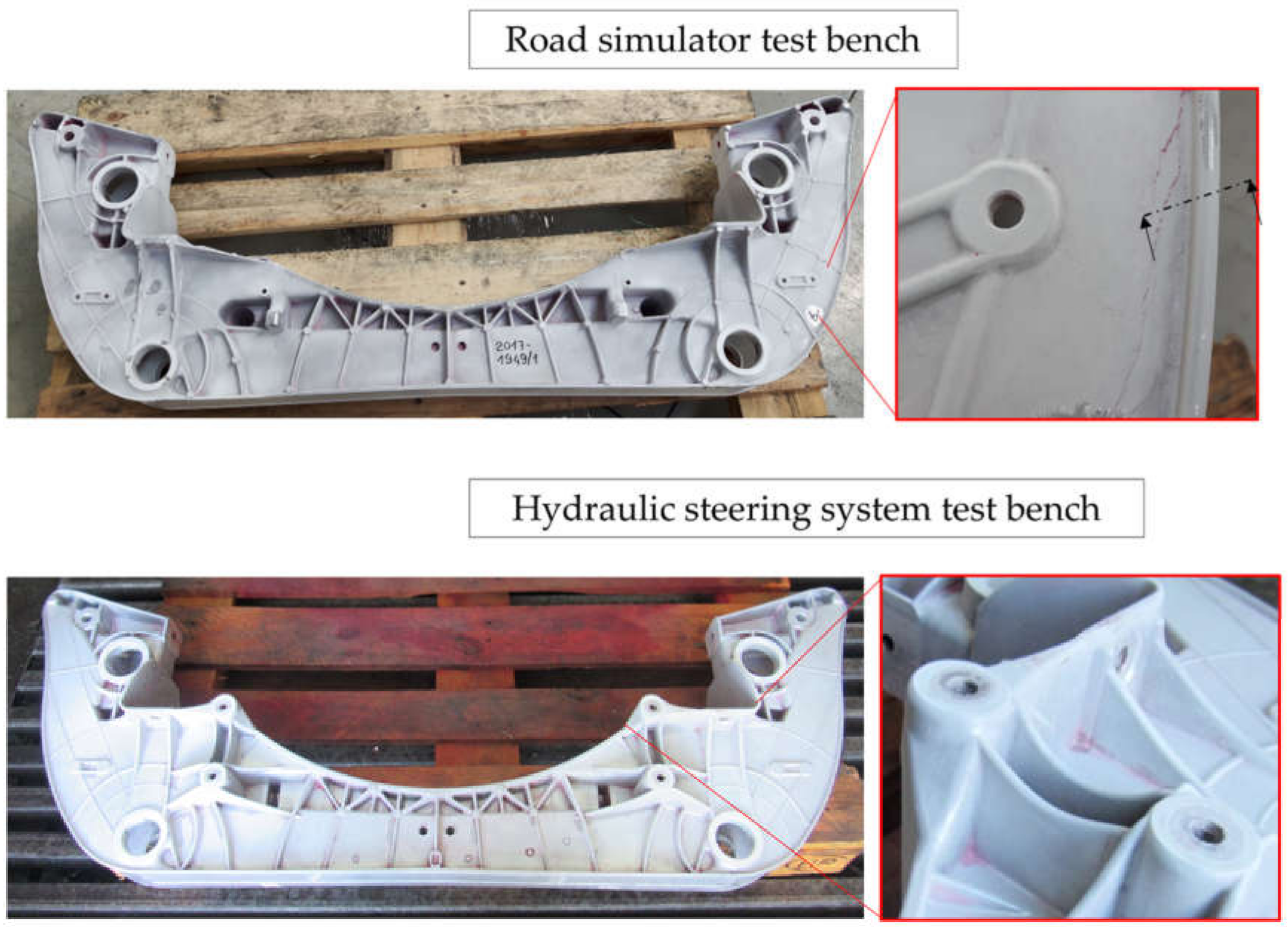
In particular, this research reports the structural simulations used for both the virtual validation of the cross member and the selection of the most appropriate features for its final configuration (design, material, technology). Then, the paper shows the results of: (i) the fatigue test bench road simulation conducted with time histories developed with reference to actual missions; and (ii) fatigue testing under hydraulic steering system loads performed on a smaller test bench. Subsequently, the model object of the research was applied in order to find a numerical comparison between the FEA and testing results.
Finally, after the test, the component was analysed by means of liquid penetrant testing and a microstructural investigation of the tested prototypes in order to confirm the absence of cracks related to the endurance tests.
It is important to highlight that the present activity is conducted on the basis of many actual data obtained from experimental tests (e.g., mission profiles and mechanical properties of components) in order to guarantee that the results are as accurate and reliable as possible. This is of great relevance, both for the validation of safety-relevant components and for unusual correlations between road simulations and FEA results.


