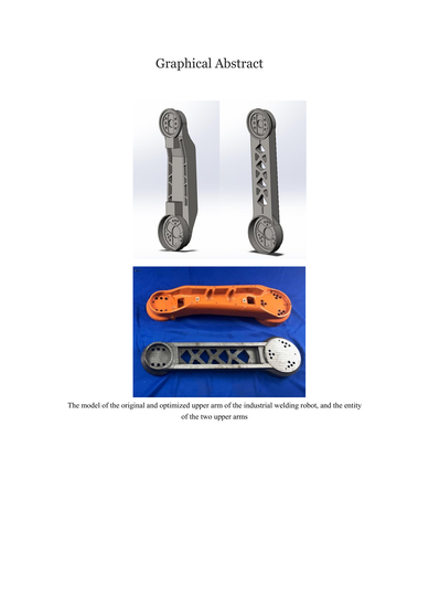
Light-Weight Topological Optimization for Upper Arm of an Industrial Welding Robot
Abstract
1. Introduction
2. Static Analysis and Kinetic Analysis of the Industrial Robot
2.1. Pretreatment of the Model
- (1)
- Effective simplification of the original model.
- (2)
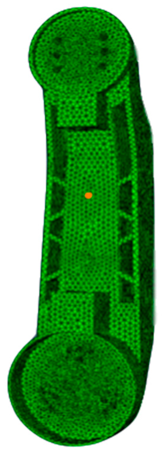
- Highly effective and accurate mesh.
- (3)
- Confirmation of the boundary and load conditions.
2.2. Static Analysis
- (1)
- The fourth failure criteria (von Mises yield criterion, also known as maximum distortion): though this theory can be suitable for the plastic material, the integrated stress distribution can be clearly shown in the Mises stress cloud map. The Mises stress is proposed to be a comprehensive criterion that determine whether the material (steel) under complex stress situations is plastic or not [31,32].
- (2)
- The first failure criteria: when the materials are brittle, such as the spheroidal graphite cast iron QT500-7, which is used for the upper arm, the maximum tensile stress in this theory should be employed to be a parameter for Yield calibration, and then should be compared with the allowable stress of the material.
- (1)
- After pretreatment of the model, all obtained load information can be transmitted into the ABAQUS, and then the Mises stress under static load can be analyzed. The equations employed by Standard Solver to be used for stress strain issue are as follows.where ε is the strain of the node result from the total extern force P, Δu is the difference between displacements of two adjacent nodes, L is the element size of the node, and I is the total internal force generated by total external force P under static equilibrium. Therefore, the total internal force should be equal to the total external force. {K} is the total stiffness matrix, while {U} is the total displacement matrix. Then the stress can be calculated by means of strain obtained through displacements.
- (2)
- Researchers transmitted the model of the industrial robot into ADAMS, and analyzed the Mises stress cloud map of the rigid–flexible coupled multi-component large displacement system. Then the most unfavorable working condition can be confirmed through dynamic simulation and static kinetic analysis, and through observing the Mises stress variation.
- (3)
- The Mises stress data and dynamic load data under the most unfavorable working condition in ADAMS can be obtained, and then the dynamic load under this condition can be transformed into an equivalent static load.
- (4)
- Transmitted the loads obtained from analyses in ADAMS into ABAQUS for accurately calculating and correspondingly analyzing the obtained criterions such as Mises stress and maximum tensile stress, and then these criterions can be compared to the stress distribution from ADAMS. Lastly, the systematic static analysis can be realized.
- (1)
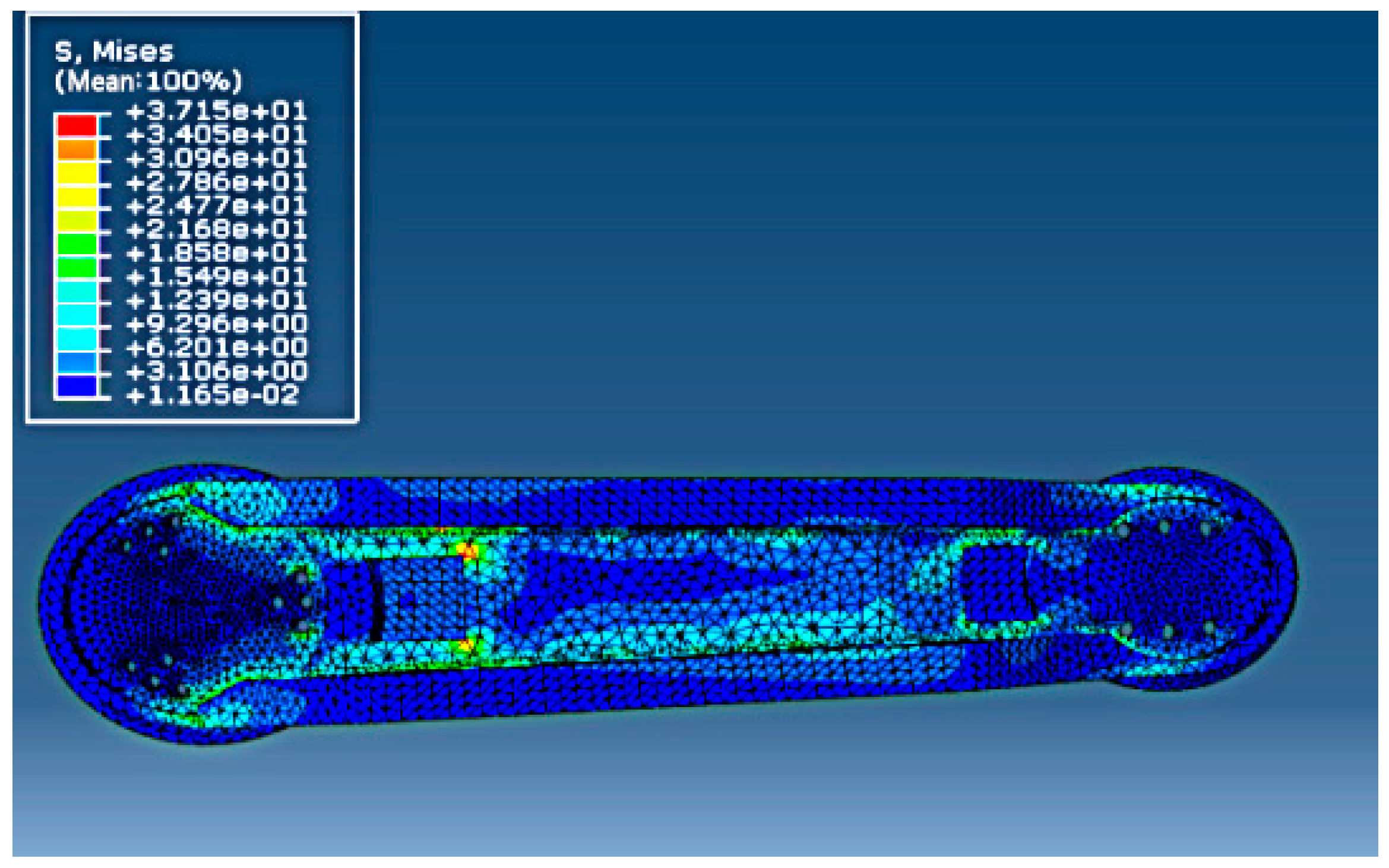
- Transmitted the model of the upper arm into ABAQUS and obtained the Mises stress distribution under static load. The result is shown in Figure 7, where it can be observed that the maximum Mises stress was 37.15 MPa.
- (2)
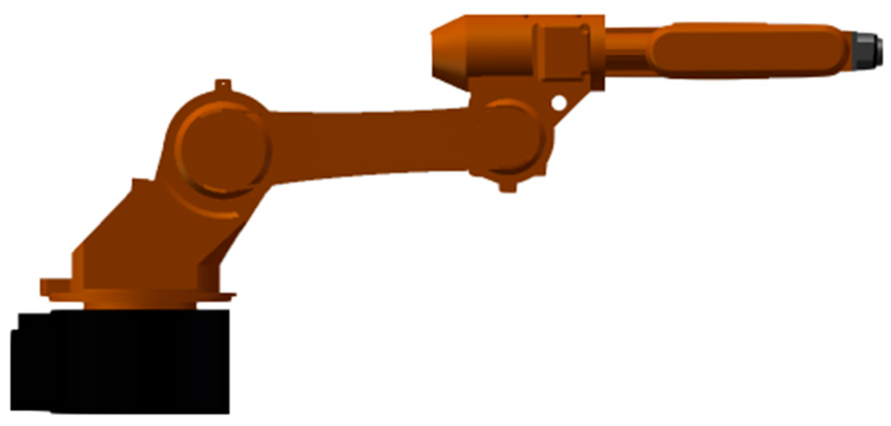
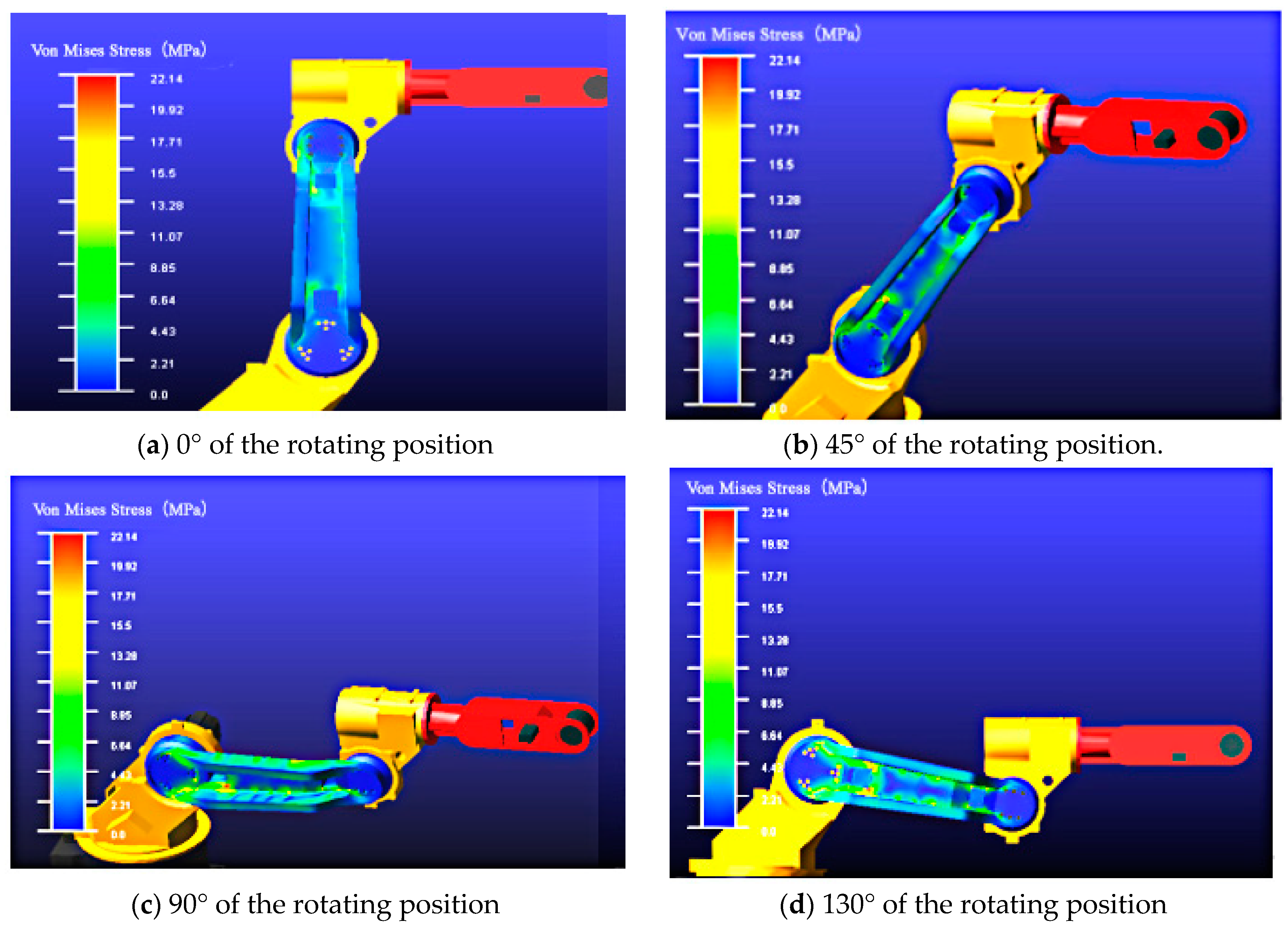
- Based on the preliminary predictions, the static force conditions under different positions within the working range of the upper arm can be obtained using ADAMS to seek the most unfavorable working condition of the upper arm. Because the model of the upper arm is symmetric, we used the constant speed of 5°/s to rotate the upper arm within the range between 0° and 130° to approximately simulate the working condition under the static circumstance. The simulation process can be shown in Figure 8.
- (3)
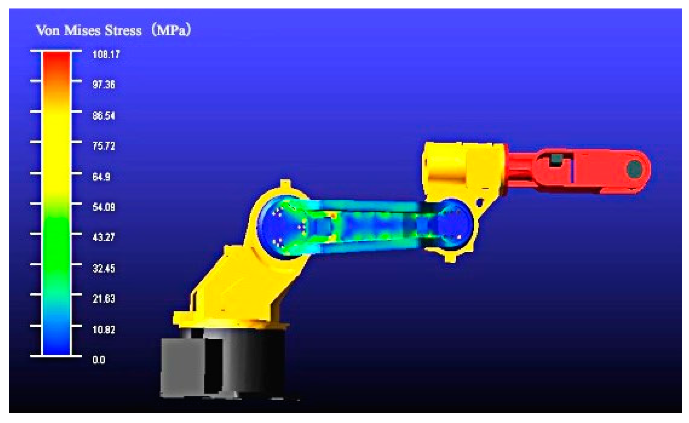
- Obtained the Mises stress data and dynamic load data in the most unfavorable working condition in ADAMS, and then transmitted the dynamic loads into corresponding static loads, as shown in Figure 9.
- (4)
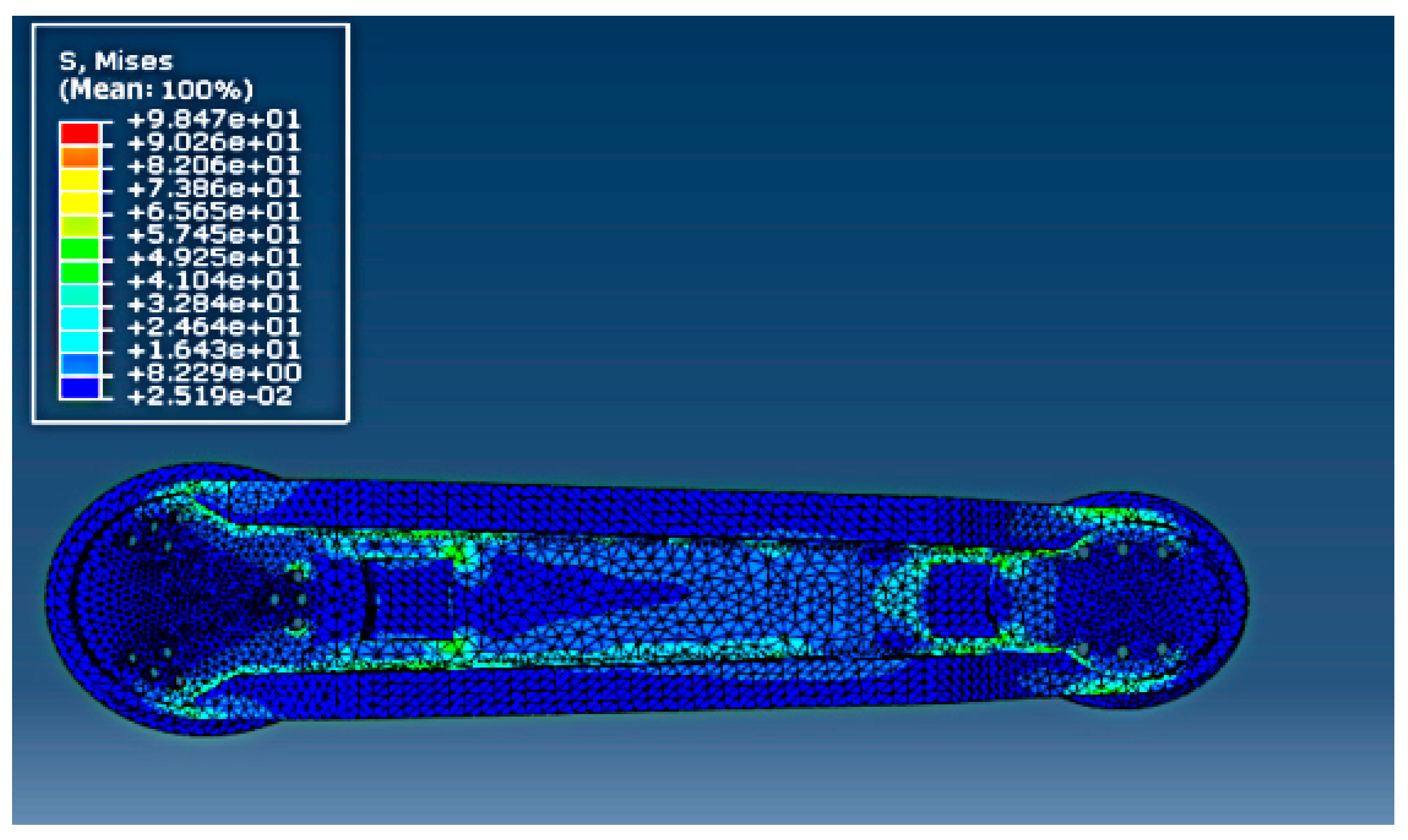
- Transmitted the loads into ABAQUS and obtained accurate calculations and analyses results. Then the transient Mises stress cloud map only for the upper arm is shown in Figure 10. The maximum Mises stress was 98.4 MPa.
2.3. Modal Analysis
- (1)
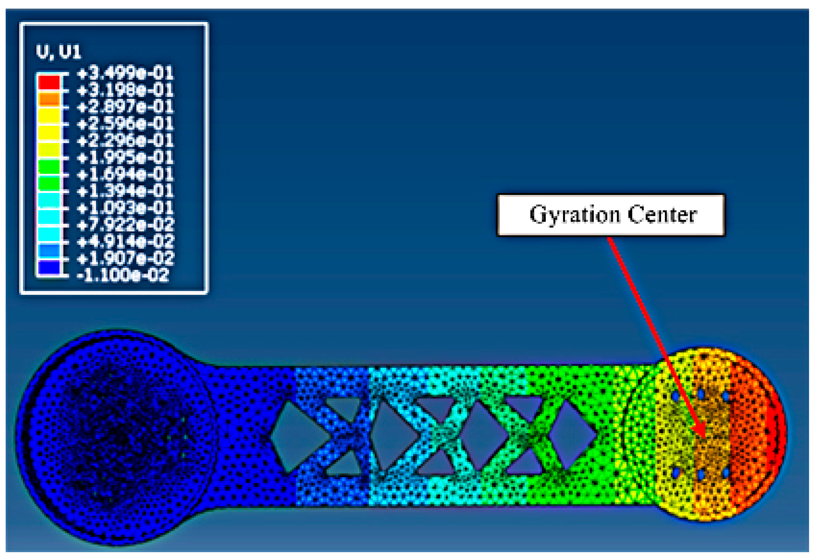
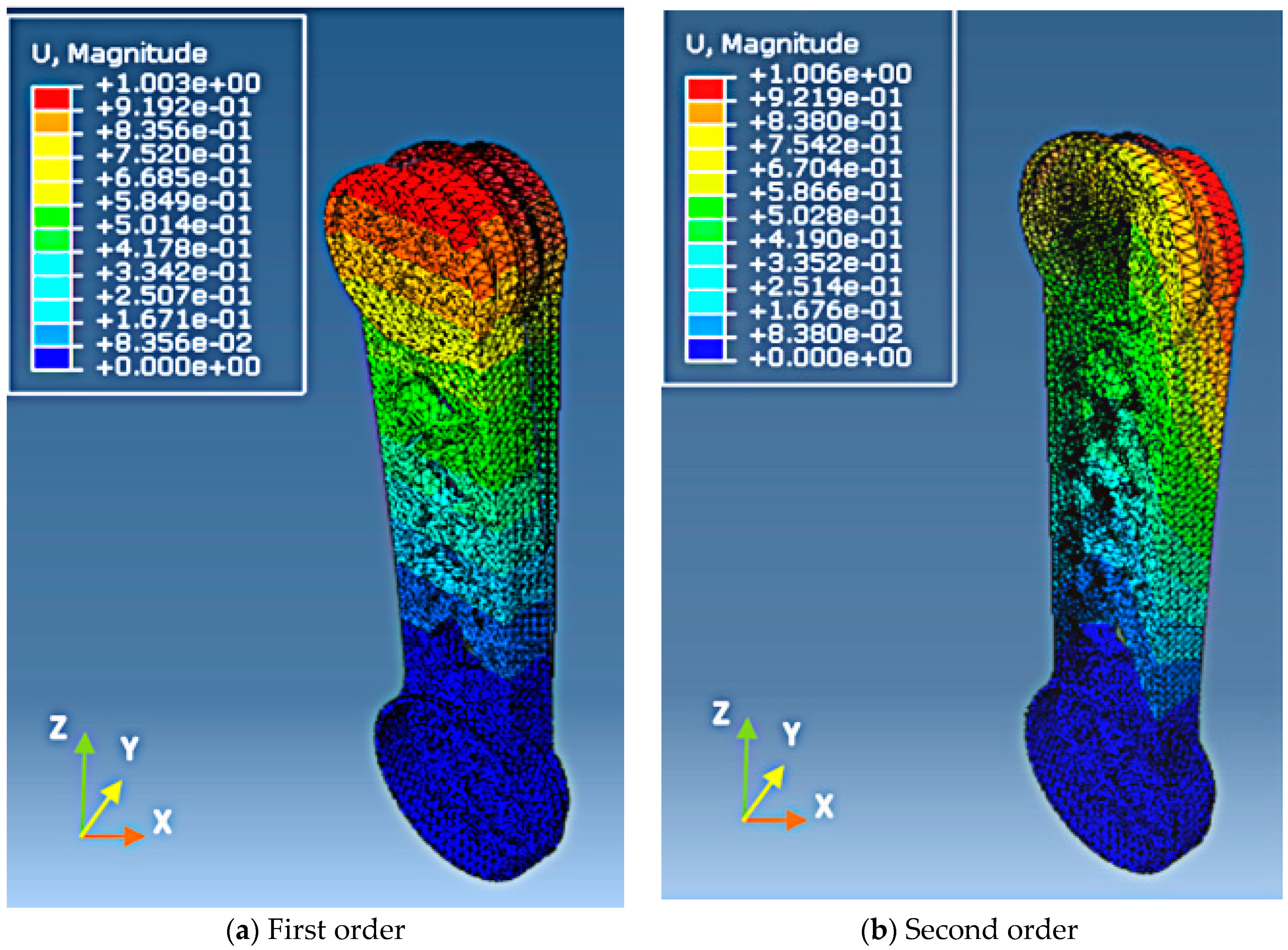
- In the first order vibration mode, the center of the vibration was the junction between the upper arm and the reducer in the second axis, and the vibration occurred along the Y axis, according to the comparison of the figures in different positions. The vibration may easily induce the fatigue failure of the junction. Hence, the rigidity of the junction should be further improved. Under the circumstance, as the distance away from the gyration center increases, the elastic displacement also increases, and the junction between the upper arm and the forearm has the largest elastic displacement.
- (2)
- In the second order vibration mode, which had the same benchmark as that in the first variation mode, the upper arm had a certain swing in the Y axis, and had a certain reverse in the Z axis. The largest elastic displacement occurred at the edge of the joint between the upper arm and the forearm.
- (3)
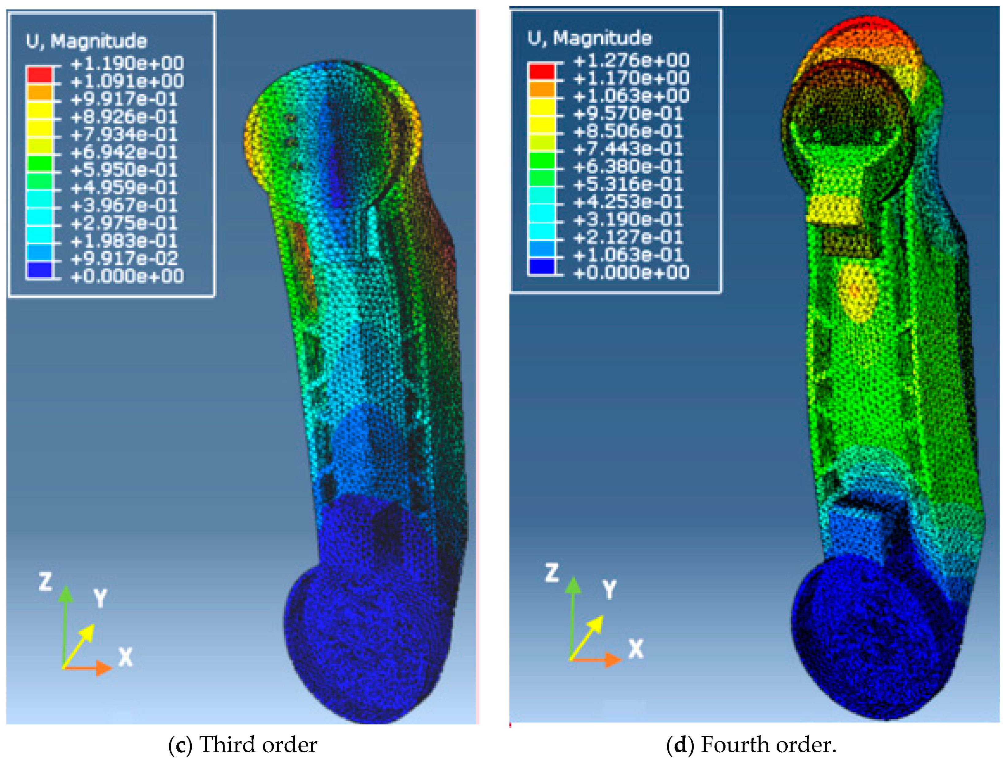
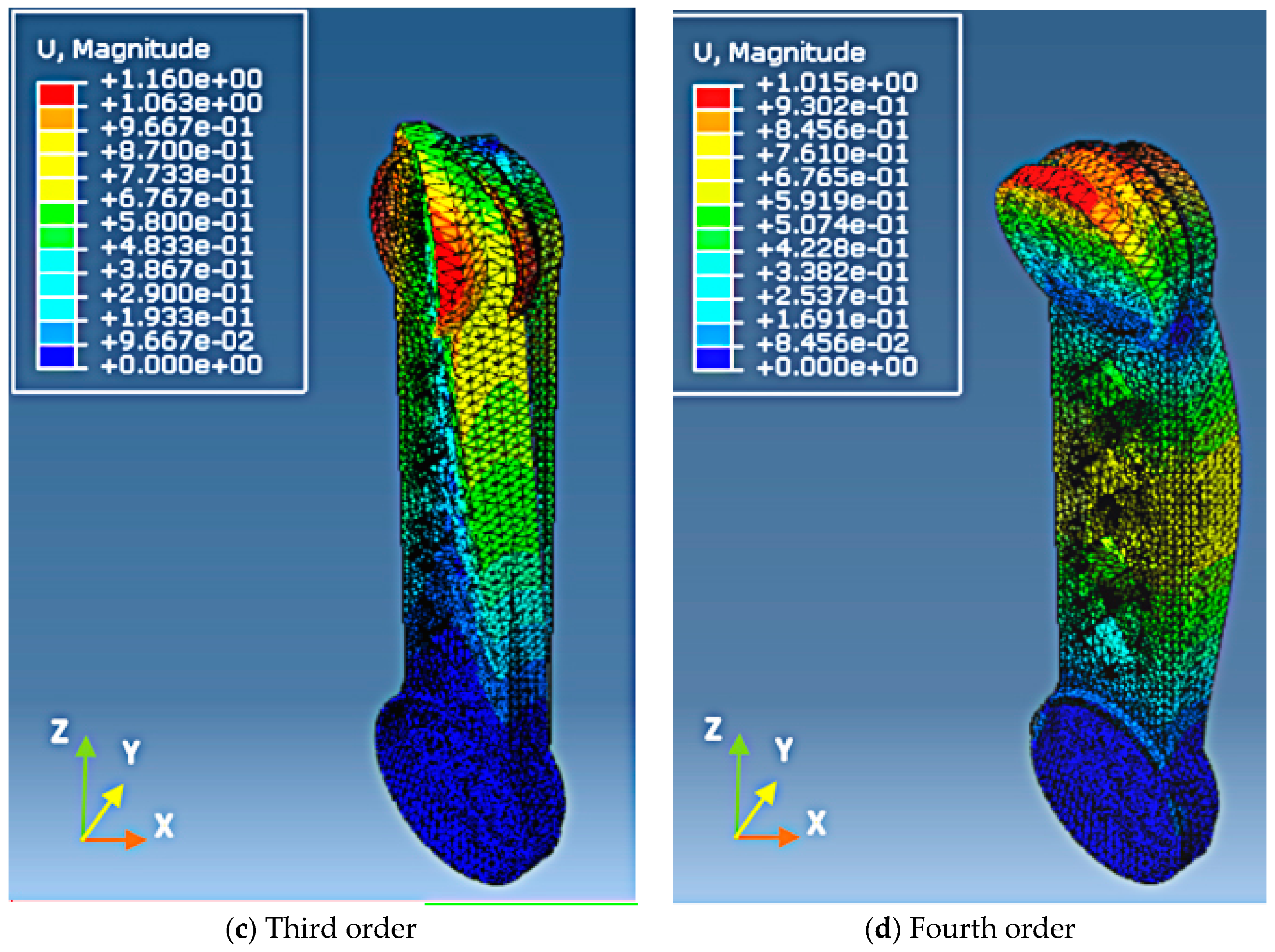
- In the third order vibration mode, the vibration was overall torsion, and the center was the middle of the upper arm, which may induce the fatigue of the middle and easily destroy the structure. The large elastic displacement was in two sides of the symmetrical axis centered on the Z axis, and the force in the back of the upper arm was very large.
- (4)
- In the fourth order vibration mode, the positioning benchmark includes the two terminates of the upper arm, the vibration occurred in the middle of the upper arm and was along the Y axis, and the largest elastic displacement occurred at the edge of the joint between the upper arm and the forearm.
3. Topological Optimization Design
3.1. Topological Optimization Theory and Procedures
3.2. Topological Optimization
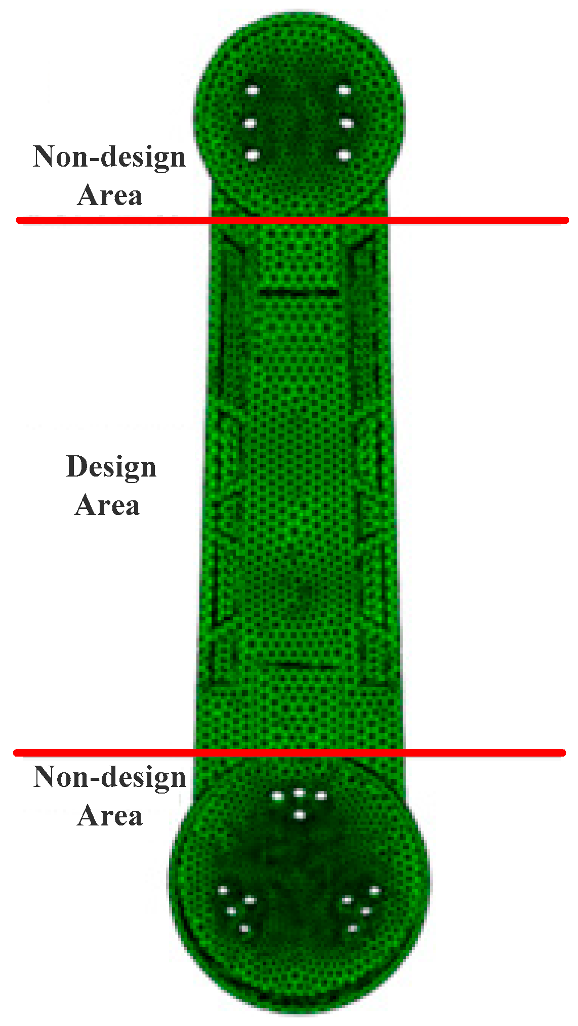
3.2.1. Division of the Design Area
3.2.2. Confirmation of the Optimization Parameters
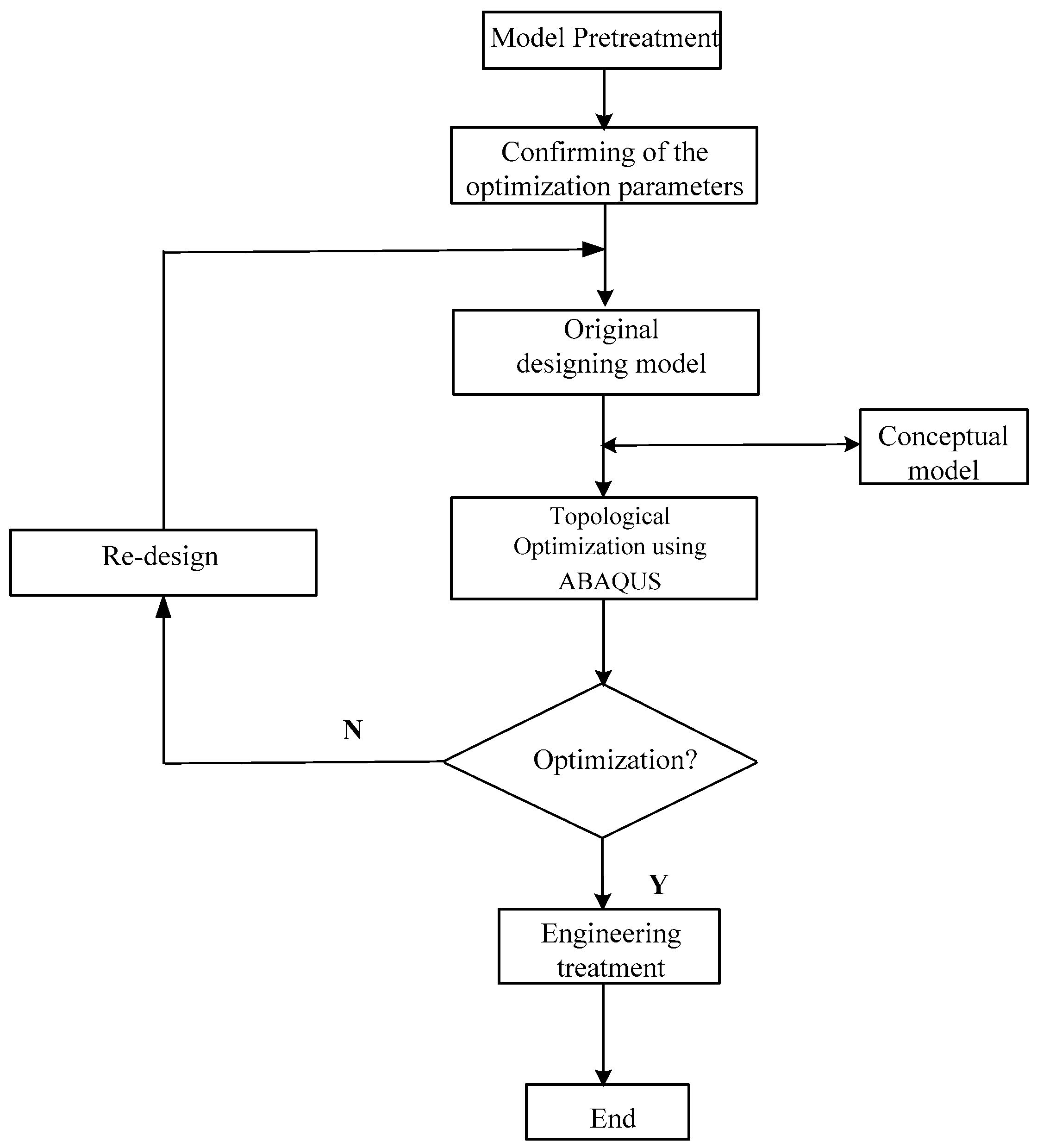
3.2.3. Design of Topological Optimization
3.3. Static Analysis of the Upper Arm after Optimization
- (1)
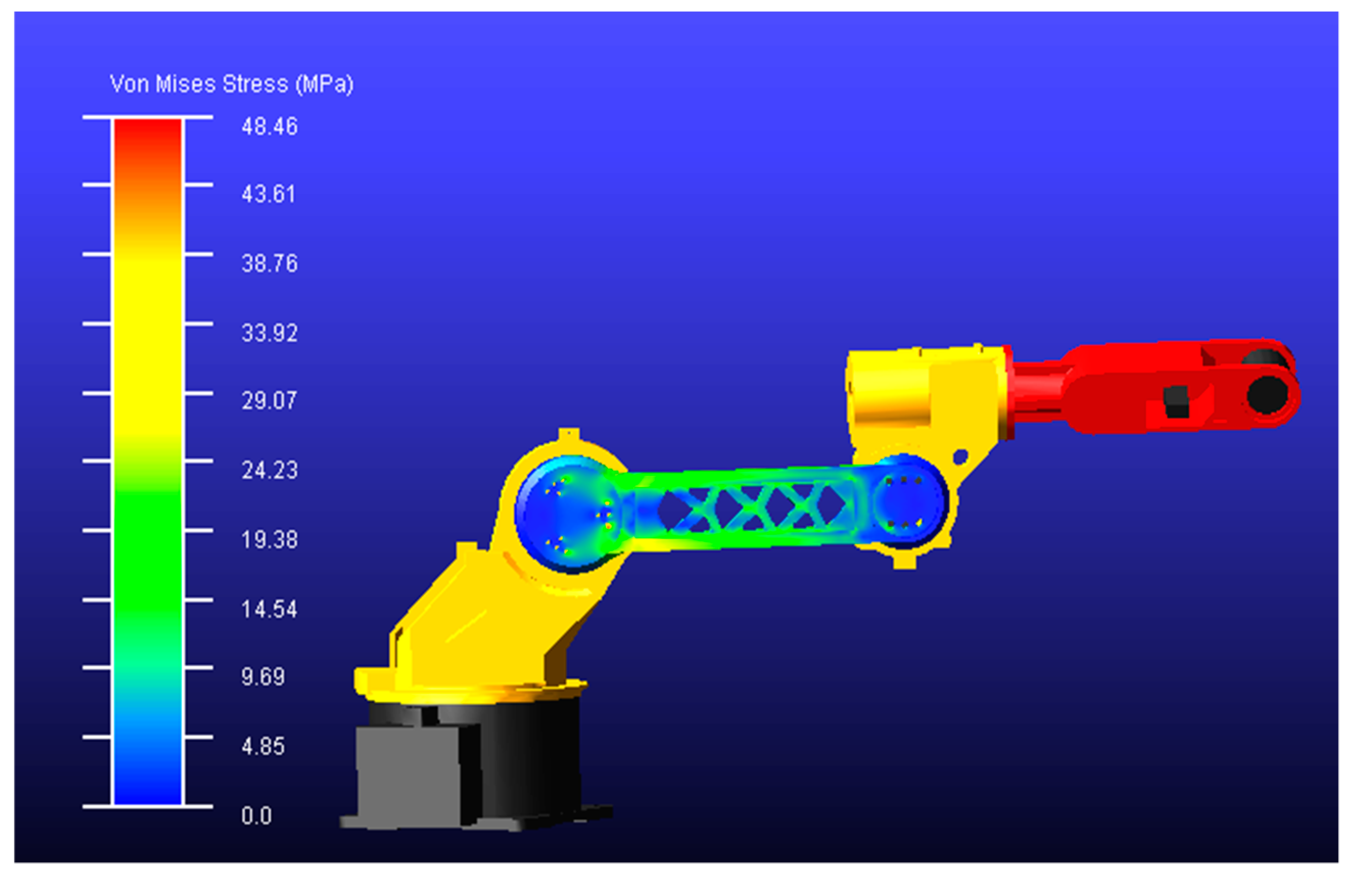
- Transmitted the model into ADAMS in order to obtain the Mises stress distribution analysis in the most unfavorable working condition, and then obtained the load information under this condition. The position of the optimized upper arm in this condition can be shown in Figure 22.
- (2)
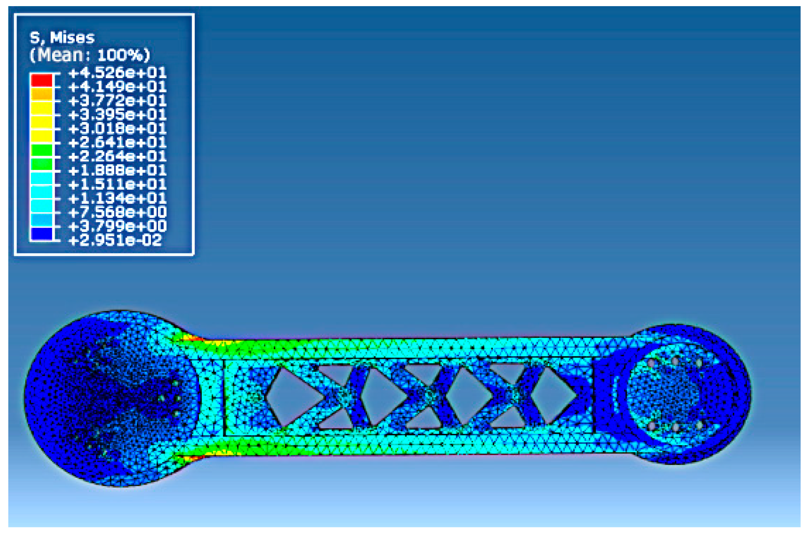
- Transmitted the model and load information of the optimized upper arm in the most unfavorable working condition into ABAQUS and obtained the corresponding Mises stress distribution analysis. The result was shown in Figure 23. Under this circumstance, the maximum Mises stress of the optimized upper arm was 45.26 MPa.
- (3)
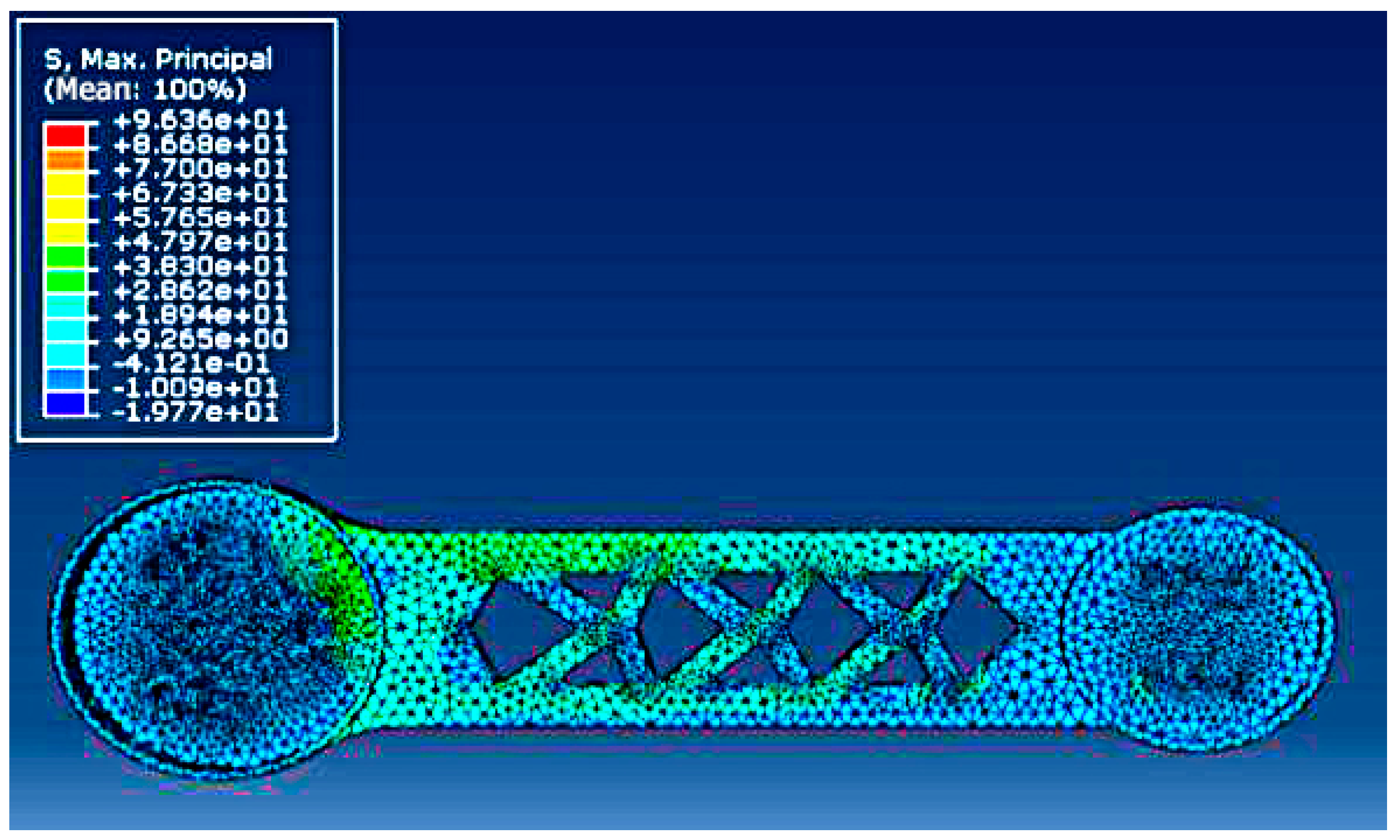
- The maximum tensile stress analysis cloud map of the optimized upper arm was shown in Figure 24. The maximum tensile stress was 96.36 MPa. The yield strength of the spheroidal graphite cast iron QT500–7 was 365 MPa, the safety coefficient of the brittle material used was 2.5, and the allowable stress was 146 MPa based on a calculation from Equation (4). It meant that the maximum force of this structure was within the allowable range of the yield strength, and the overall stress value was smaller than that before optimization.
- (4)
- When conducting the modal analysis of the optimized upper arm, the results of the first four orders vibration modes were shown in Figure 26. It can be observed that the results were approximately the same as those before optimization.
4. Experimental Validation
4.1. Experimental Platform and Method
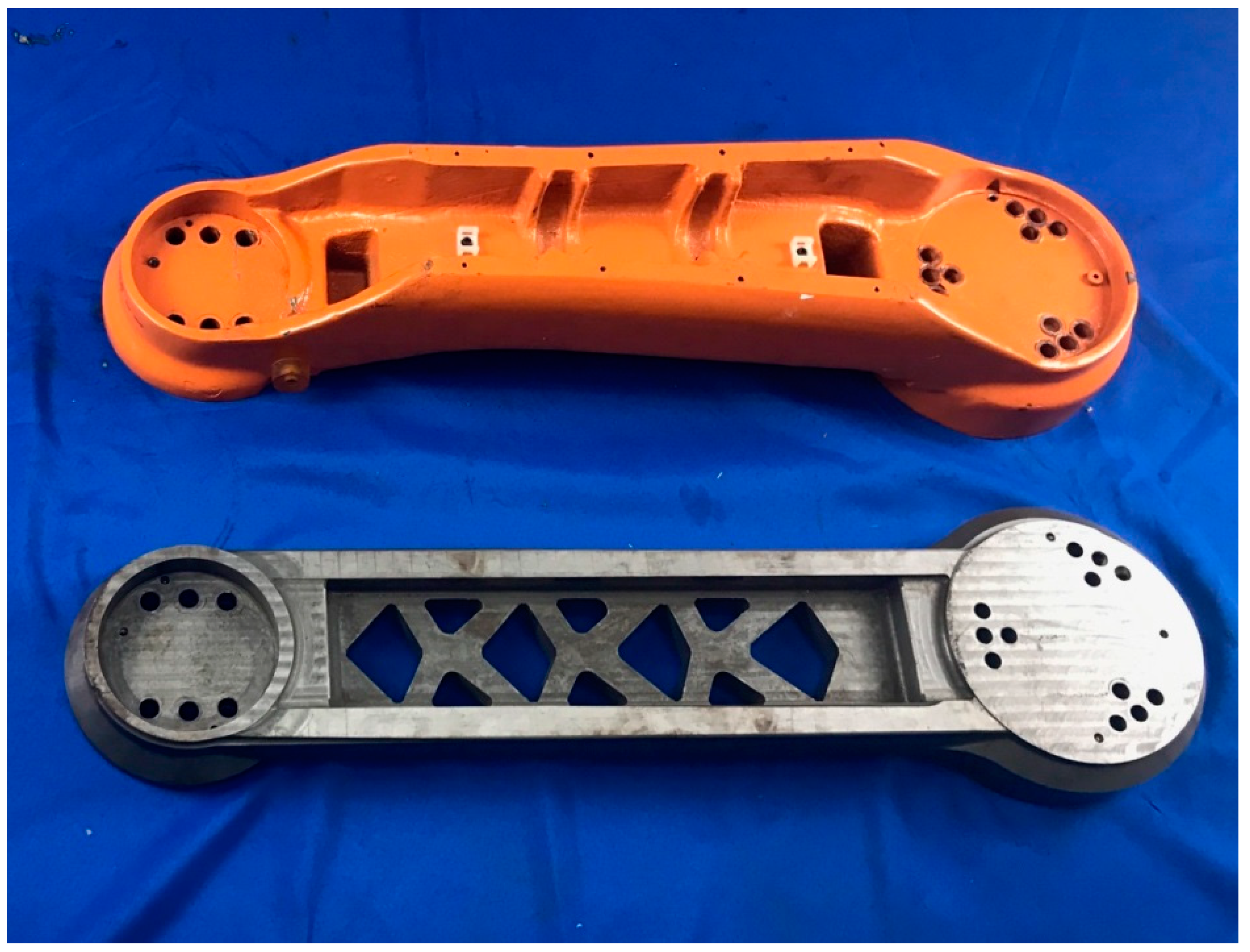
4.1.1. The Comparison between the Upper Arm before and after Optimized Design
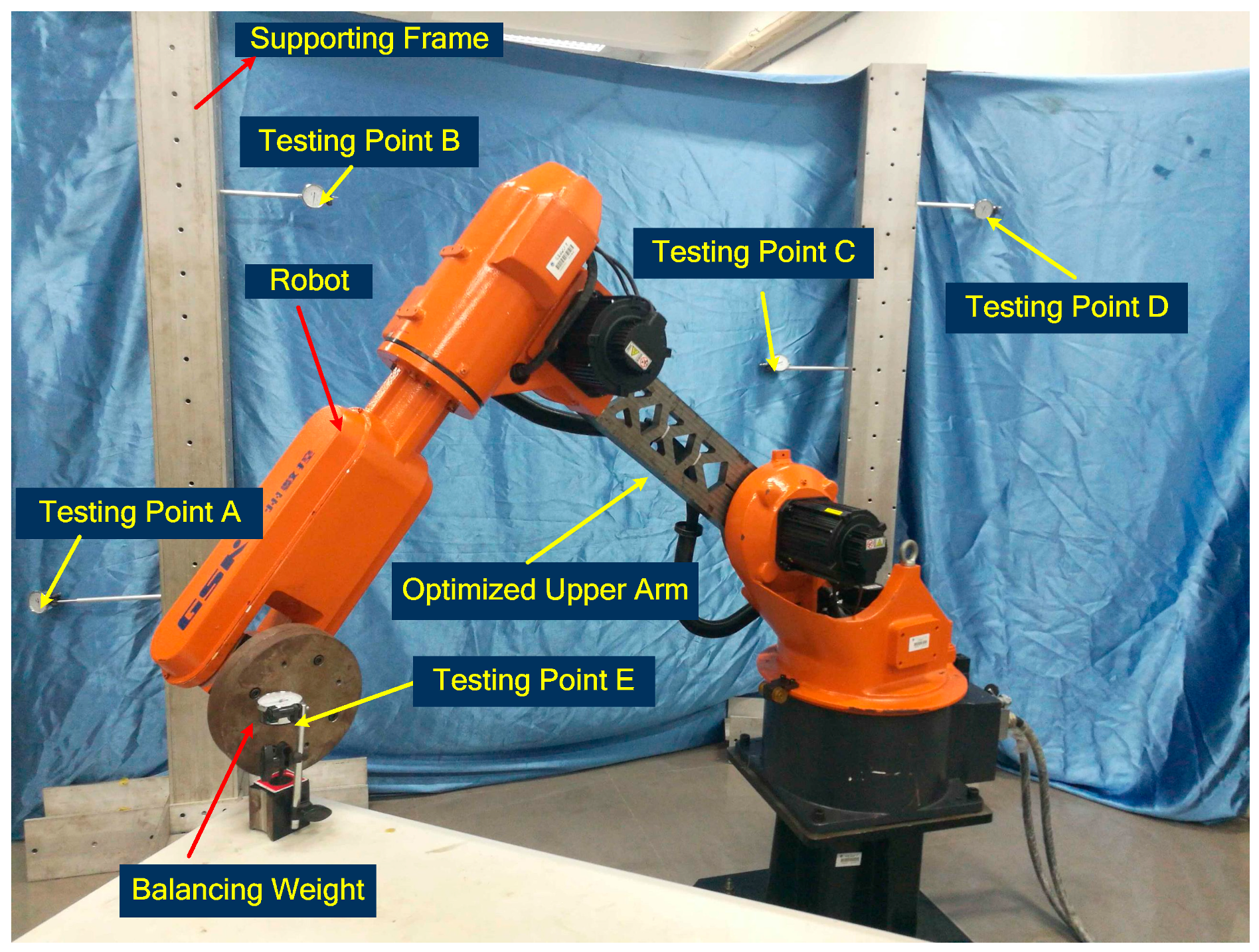
4.1.2. Experimental Platform and Procedure
4.2. Experimental Results
5. Conclusions
- (1)
- This work employed ABAQUS to conduct the static kinetic analysis, and confirmed which part of the upper arm bore the largest stress, and then employed ADAMS to simulate the static stress situation when the upper arm was at different rotating positions within its working range. According to relative numerical calculations, comparisons, and analyses, the 90° of the rotating position was confirmed as the most unfavorable working condition. At this position, the stress and elastic displacement can achieve maximum values. Then transient static kinetic analysis was conducted when the upper arm worked in the most unfavorable working condition and the dynamic load was transmitted into static load. Under this circumstance, the maximum elastic displacement of the gyration center was 0.277 mm and the Mises stress was 98.47 MPa. Using the same methods, the corresponding analyses for the optimized upper arm were also conducted, and the corresponding maximum elastic displacement was 0.267 mm with 0.01 decreasing when compared to that of the upper arm before optimization. The Mises stress was 84.2 MPa with 14.27 MPa of it decreasing.
- (2)
- The modal analyses for the upper arm in the most unfavorable working condition before and after optimization were conducted. It was observed that the natural frequency of the upper arm was very high, reaching beyond 100 Hz. In general cases, resonances cannot occur by the external urges under this condition. The natural frequencies of the optimized upper arm in different orders increased, especially after the third order. The increase was very clear.
- (3)
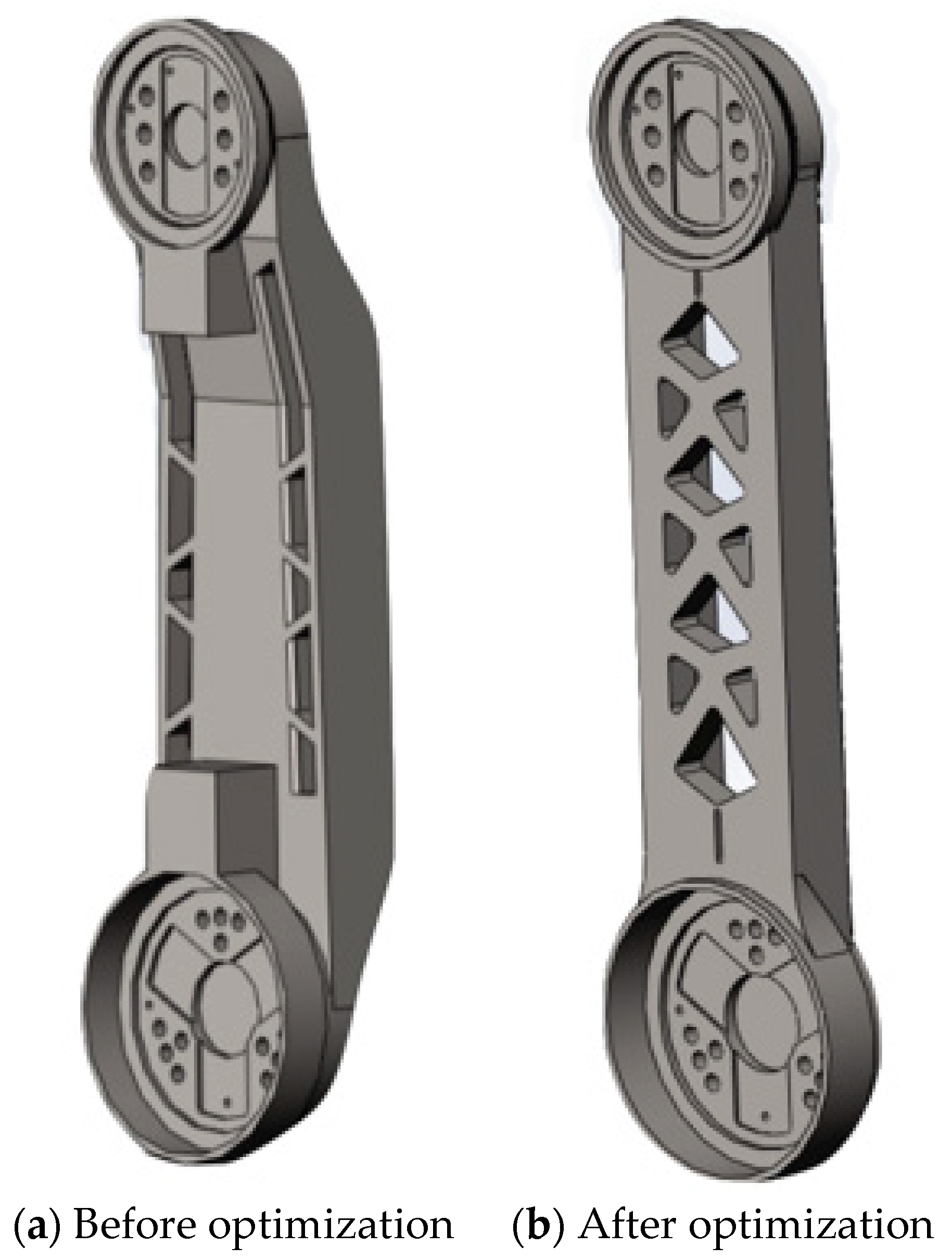
- The structural topological optimization for the upper arm had been conducted using the plug-in unit Tosca in the ABAQUS. Through the topological calculation and corresponding optimization, an optimized model can be obtained, and then an actual product processed based on the optimized model was obtained. The results of corresponding static kinetic analyses showed that the weight can be reduced 17.9% and lower order nature frequencies were increased. At the same time, the working performance remained.
- (4)
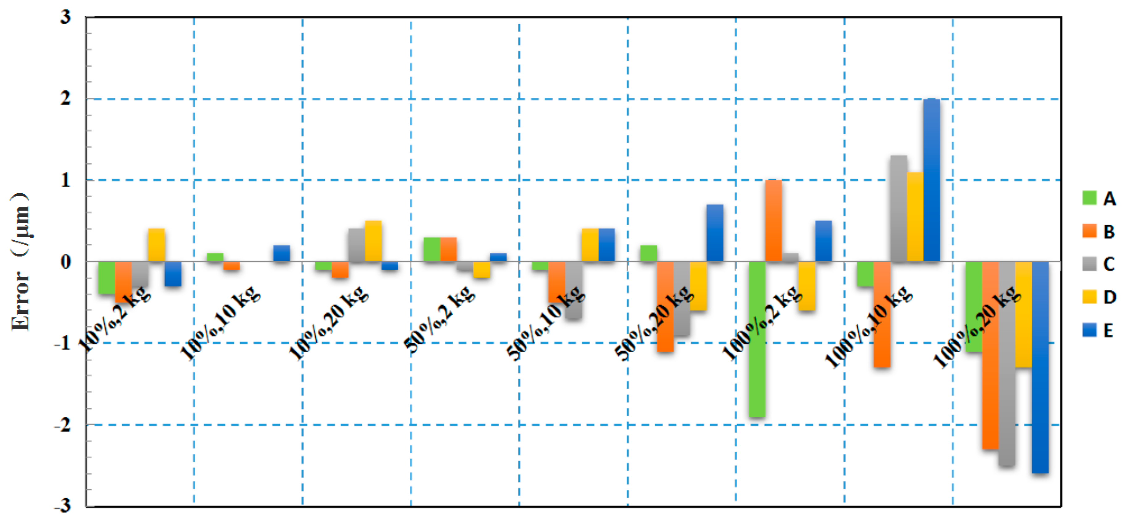
- A self-designed experimental platform and corresponding experimental method were employed to validate the effectiveness of the topological optimization of the structure. The repeatability tests using three different loads and three different moving speeds for the upper arm were conducted. The results showed that the repeatability of the optimized upper arm of the industrial robot was approximately the same as that of the original robot.
Author Contributions
Funding
Conflicts of Interest
References
- Merckaert, K.; Beir, A.D.; Adriaens, N.; Makrini, I.E.; Ham, R.V.; Vanderborght, B. Independent Load Carrying and Measurement Manipulator Robot Arm for Improved Payload to Mass Ratio. Robot. Comput. Integr. Manuf. 2018, 53, 135–140. [Google Scholar] [CrossRef]
- Zhou, K.; Yao, P. Overview of Recent Advances of Process Analysis and Quality Control in Resistance Spot Welding. Mech. Syst. Signal. Process. 2019, 124, 170–198. [Google Scholar] [CrossRef]
- Tokumoto, S.; Hirar, S. Deformation Control of Rheological Food Dough using a Forming Process Model. In IEEE International Conference. Robots Autonomous; IEEE: Washington, DC, USA, 2002; pp. 1457–1464. [Google Scholar]
- Mallapragada, V.; Sarkar, N.; Podder, T. Toward a Robot-Assisted Breast Intervention System. IEEE/ASME Trans. Mechatron. 2016, 16, 1011–1020. [Google Scholar] [CrossRef]
- Alvarez, N.; Yamazaki, K. An Interactive Simulator for Deformable Linear Objects Manipulation Planning. In IEEE International Conference on Simulation, Modeling, and Programming for Autonomous Robots (SIMPAR); IEEE: San Francisco, CA, USA, 2016. [Google Scholar]
- Park, E.; Mills, J. Static Shape and Vibration Control of Flexible Payloads with Applications to Robotic Sssembly. IEEE/ASME Trans. Mechatron. 2005, 10, 675–687. [Google Scholar] [CrossRef]
- Zhu, S.; Liu, J.; Yin, F.-L.; Meng, F.-J.; Chang, T.-Q. An Innovative Forming Method based on an Arc Welding Robot. Int. J. Adv. Manuf. Technol. 2016, 84, 1531–1538. [Google Scholar] [CrossRef]
- Ku, N.; Ha, S.; Roh, M.-I. Design of Controller for Mobile Robot in Welding Process of Shipbuilding Engineering. J. Comput. Des. Eng. 2014, 1, 243–255. [Google Scholar] [CrossRef]
- Wang, Z.-Y.; Liu, F.-Q.; Wang, X.-J. An Ear Plate Reinforced Ring Welding Robot System with Intelligent Recognition Function. In Proceedings of the 2016 IEEE Workshop on Advanced Robotics and its Social Impacts (ARSO), Shanghai, China, 8–10 July 2016. [Google Scholar]
- Shah, H.N.M.; Sulaiman, M.; Shukor, A.Z.; Kamis, Z. An Experiment of Detection and Localization in Tooth Saw Shape for Butt Joint using KUKA Welding Robot. Int. J. Adv. Manuf. Technol. 2018, 97, 3153–3162. [Google Scholar] [CrossRef]
- Kermorgant, O. A Magnetic Climbing Robot to Perform Autonomous Welding in the Shipbuilding Industry. Robot. Comput. Integr. Manuf. 2018, 53, 178–186. [Google Scholar] [CrossRef]
- Tao, Z.; Zhang, T.; Qi, M.; Ji, J. Research and Implementation of a new 6-DOF Light-weight Robot. In Proceedings of the IOP Conference Series, Earth and Environmental Science, Chengdu, China, 26–28 May 2017. [Google Scholar]
- AMRC Sheffield 2019, “Composite Center”. Available online: https://www.amrc.co.uk/facilities/composite-centre (accessed on 3 September 2019).
- 2018 Exechon Enterprises, L.L.C, “XMINI Integration”. Available online: http://www.exechon.com/integration (accessed on 3 September 2019).
- Shi, L.; Tian, X.; Zhang, C. Automatic Programming for Industrial Robot to Weld Intersecting Pipes. Int. J. Adv. Manuf. Technol. 2015, 81, 2099–2107. [Google Scholar] [CrossRef]
- Kawakami, K.; Ohkura, K.; Ueda, K. Reinforcement Learning Approach to Cooperation Problem in a Homogeneous Robot Group. In Proceedings of the ISIE 2001 2001 IEEE International Symposium on Industrial Electronics Proceedings (Cat. No.01TH8570), Pusan, Korea, 12–16 June 2001. [Google Scholar]
- Hemami, A. Studies on a Light Weight and Flexible Robot Manipulator. Robotics 1985, 1, 27–36. [Google Scholar] [CrossRef]
- Tørdal, S.S.; Hovland, G.; Tyapin, I. Efficient Implementation of Inverse Kinematics on a 6-DOF Industrial Robot using Conformal Geometric Algebra. Adv. Appl. Clifford Algebras 2017, 27, 2067–2082. [Google Scholar] [CrossRef]
- Park, C.; Jang, J.; Zhang, L.; Jung, J. Light-weight Visual Place Recognition Using Convolutional Neural Network for Mobile Robots. In Proceedings of the 2018 IEEE International Conference on Consumer Electronic, Las Vegas, NV, USA, 12–15 January 2018. [Google Scholar]
- Hegde, G.S.; Vinod, M.S.; Shankar, A. Optimum Dynamic Design of Flexible Robotic Manipulator. Int. J. Mech. Mater. Des. 2009, 5, 315–325. [Google Scholar] [CrossRef]
- Frecker, M.I.; Ananthasuresh, G.K.; NJshiwaki, S.; Kikuchi, N.; Kota, S. Topological Synthesis of Compliant Mechanisms using Multi-Criteria Optimization. Trans. ASME J. Mech. Des. 1997, 119, 238–245. [Google Scholar] [CrossRef]
- Kaveh, A.; Talatahari, S. A Hybrid Particle Swarm and Ant Colony Optimization for Design of Truss Structures. Asian J. Civ. Eng. 2008, 9, 329–348. [Google Scholar]
- Song, H.; Xue, H.; Yu, Z. Statics and Dynamics Analysis and Topology Optimization for A Six-DOF Welding Robot SR3-600. Mach. Des. Res. 2016, 32, 50–53. [Google Scholar]
- Xu, X. Strutural Analysis of Arc-welding Robot based on Finite Element Method. Master’s Thesis, Jiangnan University, Wuxi, China, 2012. [Google Scholar]
- Guan, Y.-S.; Deng, X.; Li, H.-Z.; Yin, Z.-N.; Wu, W.-Q.; Jiang, L. Structural Analysis and Optimization of Industrial Robot. J. South China Univ. Technol. (Nat. Sci. Ed.) 2013, 41, 126–131. [Google Scholar]
- Chen, G.; Wang, L.; Jia, Q.; Wang, S. Calibration Method and Simulation of Kinematic Parameters for Light-Weight Robot Based on Flexible Error Analysis. In Proceedings of the 2017 2nd International Conference on Cybernetics, Robotics and Control, Chengdu, China, 21–23 July 2017. [Google Scholar]
- Albu-Schäffer, A.; Haddadin, S.; Ott, C..; Stemmer, A.; Wimböck, T.; Hirzinger, G. The DLR lightweight robot: design and control concepts for robots in human environments. Ind. Robot Int. J. 2007, 34, 376–385. [Google Scholar]
- Meenakshi, S.; Srinivas, N.; Siddarth, Y.S.; Kamal, C.V.S.; Sudheendra, K.; Bhowmik, S.; Pitchan, M.K.; Epaarachchi, J.A. Numerical Analysis of State of the Art High Performance Thermoplastic Composite as Light Weight Bullet Proof Material. Mater. Res. Express 2019, 6, 095333. [Google Scholar]
- Santolaria, J.; Aguilar, J.J.; Samper, D.; Brosed, F.J.; Majarena, A.C. Software Simulation Platform for Learning Techniques for Identifying Kinematic Parameters of Industrial Robots. In Proceedings of the 2011 Promotion and Innovation with New Technologies in Engineering Education (FINTDI 2011), Teruel, Spain, 5–6 May 2011. [Google Scholar]
- de Diego-Calderón, I.; Issaoui, A.; Hell, J.-C.; Zuazo, I. Phase Stability Investigation of Light-weight Alloys based on the FeMnAlC System. Metall. Res. Technol. 2019, 116, 424. [Google Scholar] [CrossRef]
- Yu, H.; Yoshimine, M.; Qiang, H.; Zan, Y.; Xiao, Y.; Li, L.; Sheng, Z. Advances and Prospects for Strength Theory. Eng. Mech. 2004, 21, 1–20. (In Chinese) [Google Scholar]
- Mises, R.V. Mechanik der festen Körper im plastisch-deformablen Zustand. Nachrichten von der Gesellschaft der Wissenschaften zu Gottingen (Mathematisch-physikalische Klasse 1913, 1, 582–592. [Google Scholar]
- Rietz, A. Sufficiency of a Finite Exponent in SIMP (power law) Methods. Struct. Multidiscip. Optim. 2001, 21, 159–163. [Google Scholar] [CrossRef]
- Liu, A.; Tang, X.; Lu, F. Study on Welding Process and Prosperities of AA5754 Al-alloy Welded by Double Pulsed Gas Metal Arc Welding. Mater. Des. 2013, 50, 149–155. [Google Scholar] [CrossRef]








| Material | QT500–7 |
|---|---|
| Density (Kg/m3) | 7300 |
| Young’s (elastic) Modulus (Pa) | 1.9 × 10¹¹ |
| Poisson Ratio | 0.28 |
| Tensile Strength (MPa) | 500 |
| Yield Strength (MPa) | 365 |
| Positions (°) | Mises Stress (MPa) |
|---|---|
| 0 | 6.56 |
| 45 | 15.491 |
| 90 | 22.137 |
| 130 | 19.843 |
| Item | Static | Transient in the Most Unfavorable Working Condition |
|---|---|---|
| Maximum Mises Stress (MPa) | 37.15 | 98.47 |
| Maximum Tensile Stress (MPa) | 38.9 | 109.6 |
| Maximum Displacement of the Gyration Center (mm) | 0.142 | 0.277 |
| Order | 1st | 2nd | 3rd | 4th | 5th | 6th |
| Frequency/Hz | 104.62 | 190.08 | 251.45 | 566.28 | 702.10 | 709.38 |
| Order | 7th | 8th | 9th | 10th | 11th | 12th |
| Frequency/Hz | 1309.0 | 1385.6 | 1410.7 | 1452.8 | 1536.7 | 1647.8 |
| Item | Transient in the Most Unfavorable Working Condition |
|---|---|
| Max Mises Stress (MPa) | 84.2 |
| Maximum Tensile Stress (MPa) | 96.36 |
| Maximum Displacement of the Gyration Center (mm) | 0.267 |
| Order | 1st | 2nd | 3rd | 4th | 5th | 6th |
| Frequency/Hz | 107.42 | 216.75 | 363.53 | 587.68 | 1143.8 | 1274.0 |
| Order | 7th | 8th | 9th | 10th | 11th | 12th |
| Frequency/Hz | 1363.6 | 1567.7 | 2427.7 | 2519.2 | 2686.4 | 2924.8 |
| Criterion (Unit) | Original | Optimized | Comparison |
|---|---|---|---|
| Mass (Kg) | 33.5 | 27.5 | Decreased 17.9% |
| Maximum Mises Stress (MPa) | 98.47 | 84.2 | Decreased 14.27 MPa |
| Maximum Tensile Stress (MPa) | 109.6 | 96.36 | Decreased 12.64 MPa |
| Maximum Elastic Displacement of the Gyration Center (mm) | 0.277 | 0.266 | Decreased 0.01 mm |
| First Order Nature Frequency (Hz) | 104.62 | 107.42 | Increased 2.8 Hz, about 2.68% |
| Second Order Nature Frequency (Hz) | 190.8 | 216.75 | Increased 25.95 Hz, about 13.6% |
| Third Order Nature Frequency (Hz) | 251.45 | 363.53 | Increased 112.08 Hz, about 44.57% |
| Fourth Order Nature Frequency (Hz) | 566.28 | 587.68 | Increased 21.4 Hz, about 3.71% |
| Speed | Mass of the Load | Original Upper Arm (times) | Optimized Upper Arm (times) |
|---|---|---|---|
| 10% | 2 kg | 100 | 100 |
| 10 kg | 100 | 100 | |
| 20 kg | 100 | 100 | |
| 50% | 2 kg | 100 | 100 |
| 10 kg | 100 | 100 | |
| 20 kg | 100 | 100 | |
| 100% | 2 kg | 100 | 100 |
| 10 kg | 100 | 100 | |
| 20 kg | 100 | 100 | |
| Total times | 900 | 900 | |
| Testing Points | A | B | C | D | E | ||||||
|---|---|---|---|---|---|---|---|---|---|---|---|
| Speed | Mass of the Load | Before | After | Before | After | Before | After | Before | After | Before | After |
| 10% | 2 kg | 7.2 | 6.8 | 10.2 | 9.7 | 9.5 | 9.2 | 7.2 | 7.6 | 8.8 | 8.5 |
| 10 kg | 8.3 | 8.4 | 10.5 | 10.4 | 9.7 | 9.7 | 7.8 | 7.8 | 9.2 | 9.4 | |
| 20 kg | 9.2 | 9.1 | 11 | 10.8 | 9.8 | 10.2 | 8.9 | 9.4 | 10.2 | 10.1 | |
| 50% | 2 kg | 9.4 | 9.7 | 12 | 12.3 | 9.6 | 9.5 | 7.5 | 7.3 | 9.2 | 9.3 |
| 10 kg | 9.8 | 9.7 | 13.4 | 12.9 | 10.5 | 9.8 | 7.8 | 8.2 | 9.8 | 10.2 | |
| 20 kg | 10.2 | 10.4 | 14.6 | 13.5 | 14.3 | 13.4 | 13.5 | 12.9 | 9.8 | 10.5 | |
| 100% | 2 kg | 16.6 | 14.7 | 19.5 | 20.5 | 15.6 | 15.7 | 17.2 | 16.6 | 16.6 | 17.1 |
| 10 kg | 22 | 21.7 | 25.6 | 24.3 | 19.9 | 21.2 | 18.4 | 19.5 | 18.7 | 20.7 | |
| 20 kg | 30.4 | 29.3 | 33 | 30.7 | 32.3 | 29.8 | 32.6 | 31.3 | 31.2 | 28.6 | |
© 2019 by the authors. Licensee MDPI, Basel, Switzerland. This article is an open access article distributed under the terms and conditions of the Creative Commons Attribution (CC BY) license (http://creativecommons.org/licenses/by/4.0/).
Share and Cite
Yao, P.; Zhou, K.; Lin, Y.; Tang, Y. Light-Weight Topological Optimization for Upper Arm of an Industrial Welding Robot. Metals 2019, 9, 1020. https://doi.org/10.3390/met9091020
Yao P, Zhou K, Lin Y, Tang Y. Light-Weight Topological Optimization for Upper Arm of an Industrial Welding Robot. Metals. 2019; 9(9):1020. https://doi.org/10.3390/met9091020
Chicago/Turabian StyleYao, Ping, Kang Zhou, Yuan Lin, and Yong Tang. 2019. "Light-Weight Topological Optimization for Upper Arm of an Industrial Welding Robot" Metals 9, no. 9: 1020. https://doi.org/10.3390/met9091020
APA StyleYao, P., Zhou, K., Lin, Y., & Tang, Y. (2019). Light-Weight Topological Optimization for Upper Arm of an Industrial Welding Robot. Metals, 9(9), 1020. https://doi.org/10.3390/met9091020


