Microstructure and Mechanical Performance of the DD98M-DD98M Single Crystal Superalloy Joints Brazed Using a Pd-Si Composite Filler

 , , , ,
Abstract
:1. Introduction
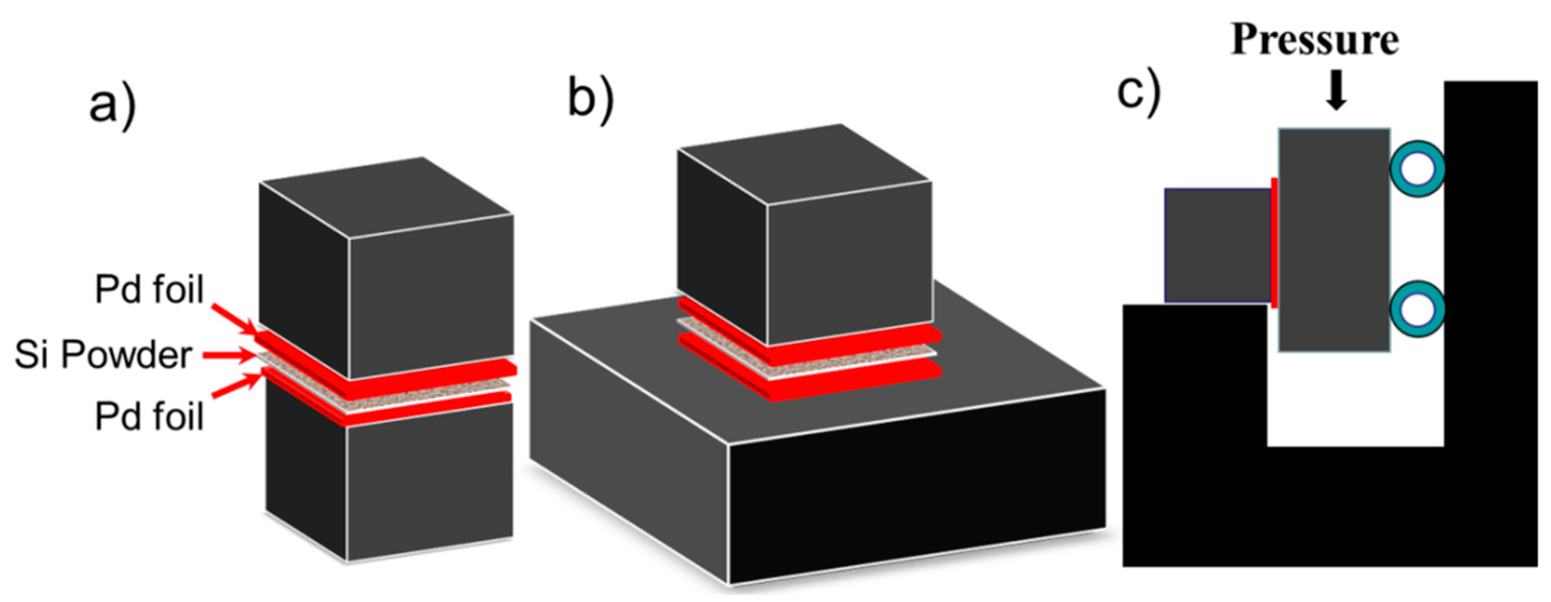
2. Materials and Methods
3. Results and Discussions
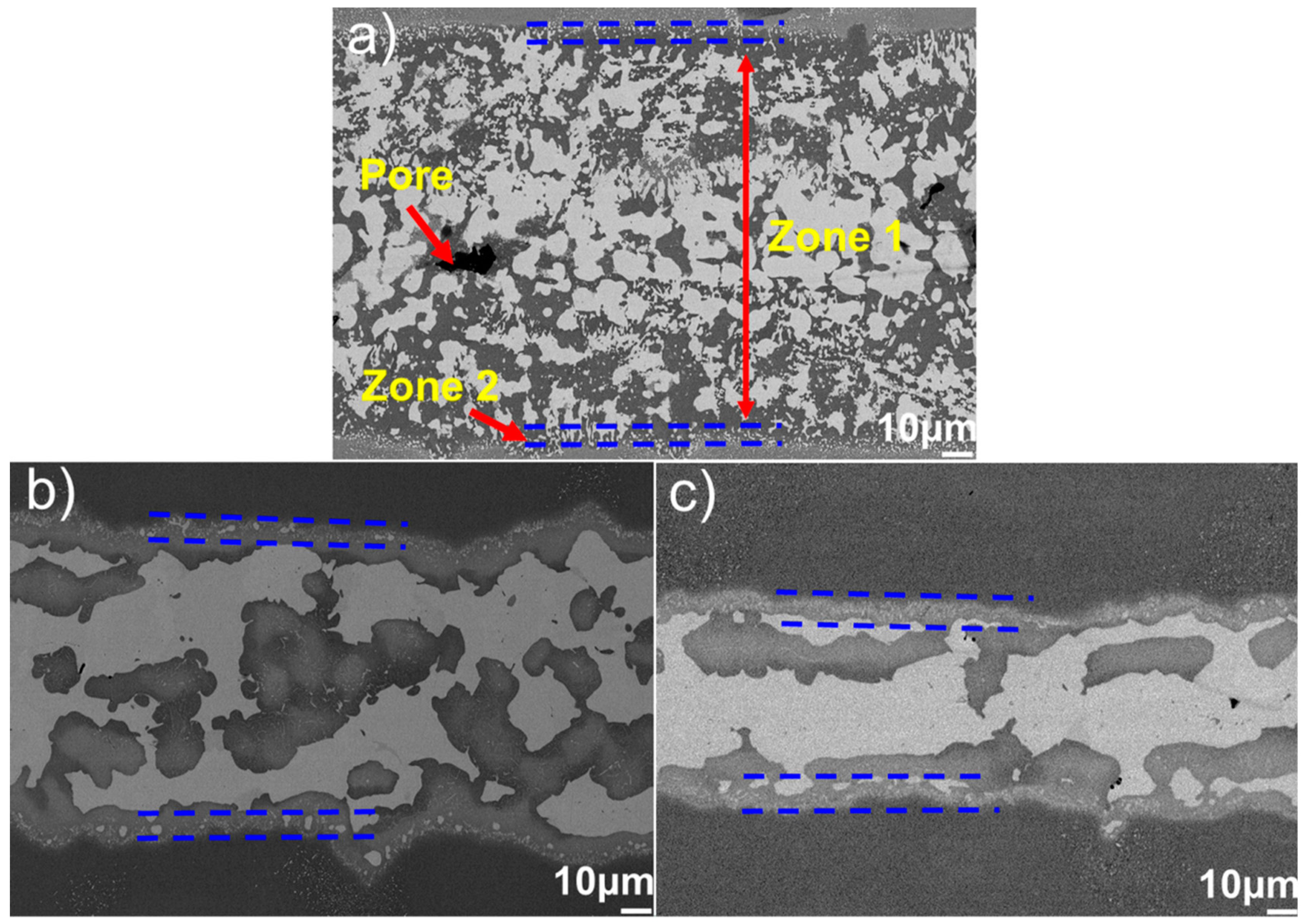
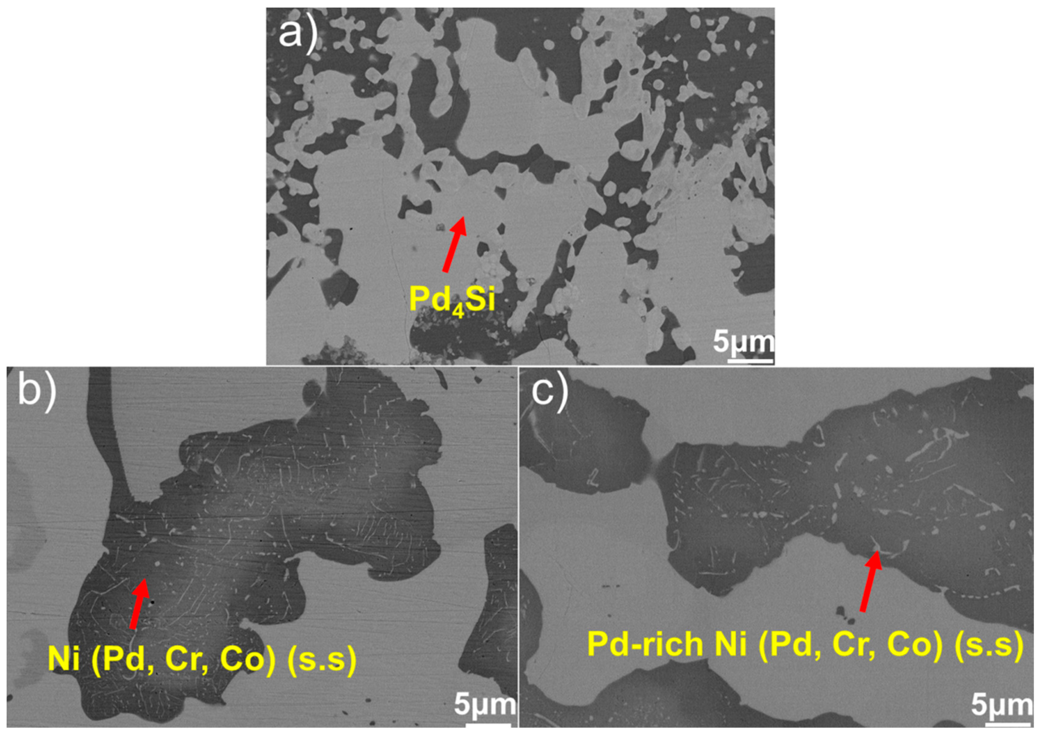
3.1. Microstructural Characterization
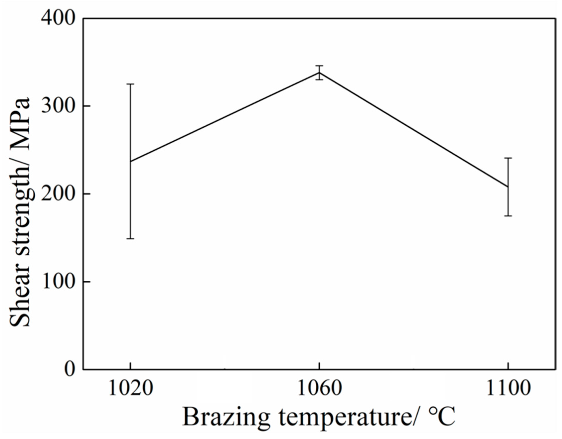
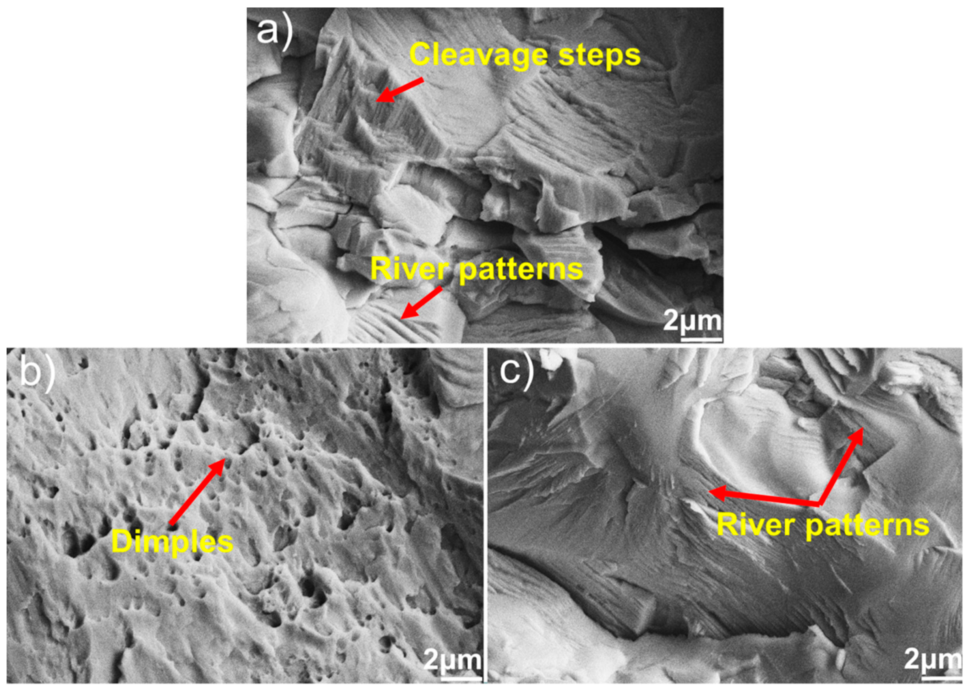
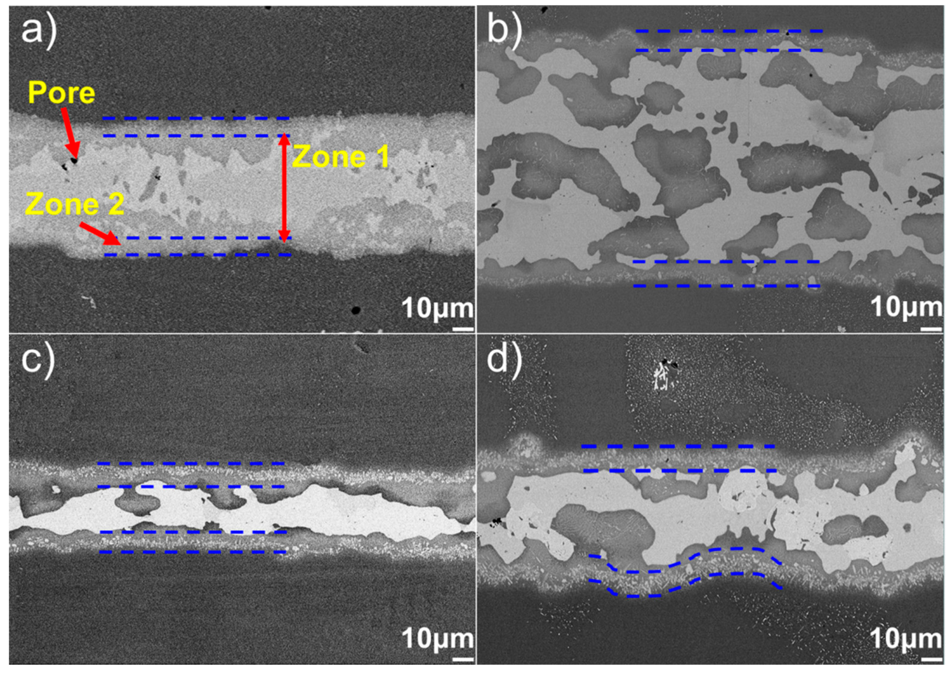
3.2. Effect of Brazing Temperature on the Microstructure and Mechanical Properties of the Joint
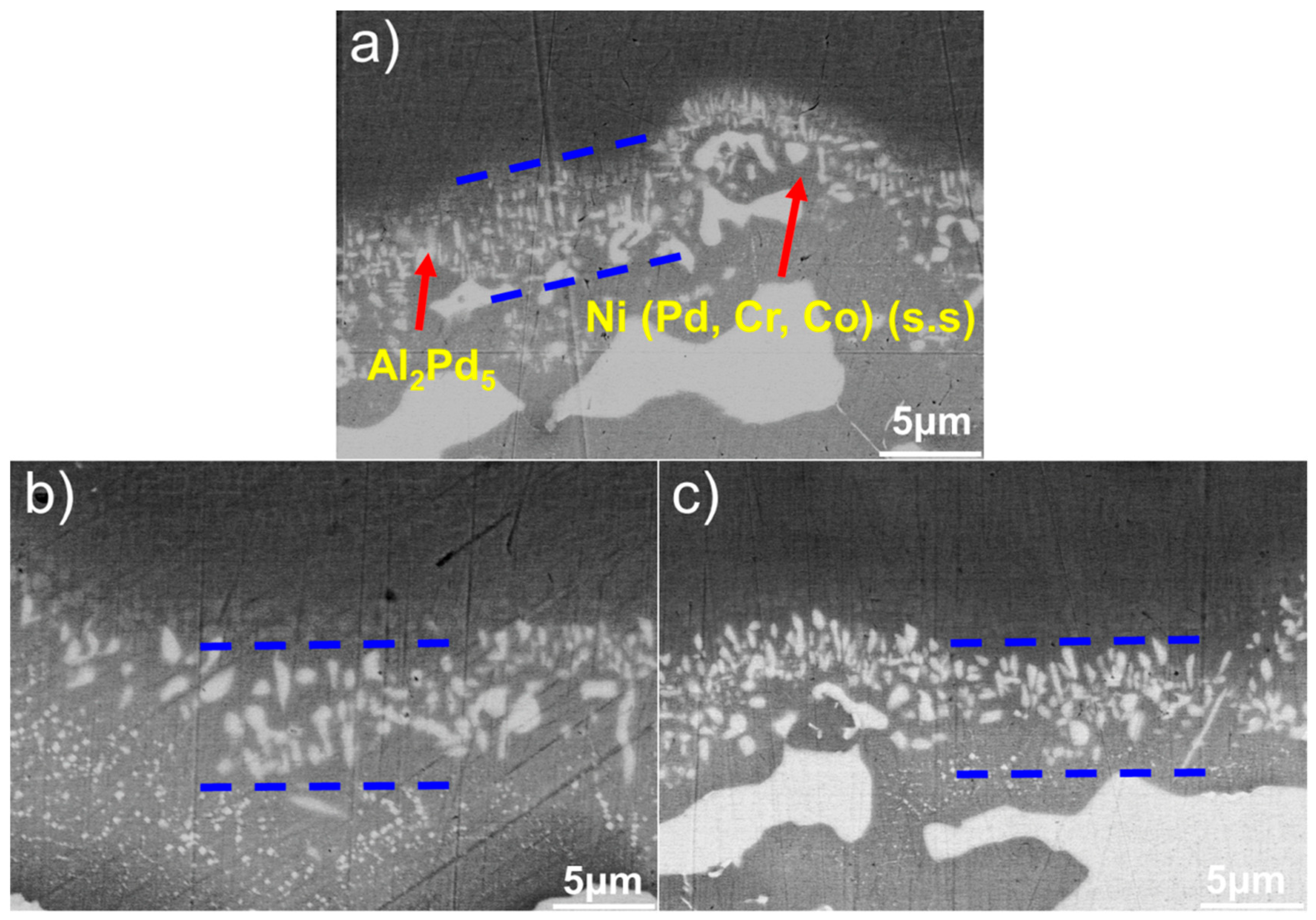
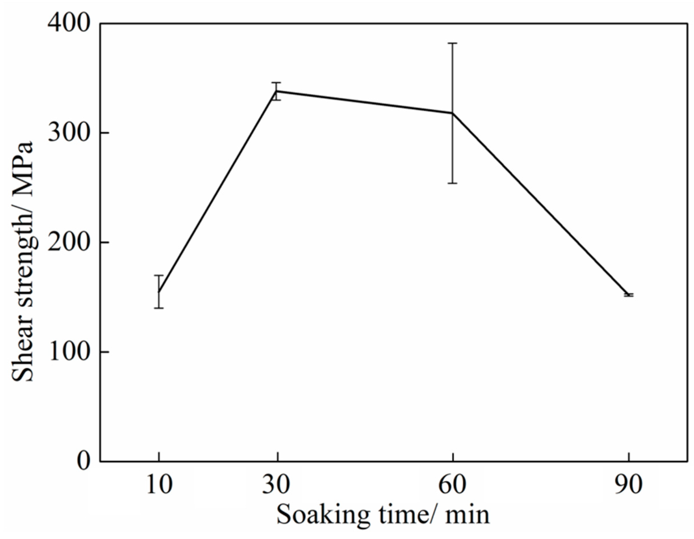
3.3. Effect of Soaking Time on the Microstructure and Mechanical Properties of the Joint
4. Conclusions
Author Contributions
Funding
Conflicts of Interest
References
- Conduit, B.D.; Jones, N.G.; Stone, H.J.; Conduit, G.J. Design of a nickel-base superalloy using a neural network. Mater. Des. 2017, 131, 358–365. [Google Scholar] [CrossRef] [Green Version]
- Zhang, J.X.; Murakumo, T.; Koizumi, Y.; Kobayashi, T.; Harada, H. Slip geometry of dislocations related to cutting of the γ′ phase in a new generation single-crystal superalloy. Acta Mater. 2003, 51, 5073–5081. [Google Scholar] [CrossRef]
- Xuan, Q.; Chen, Z.Z.; Liu, Y.; Huang, H.M.; Bao, G.J.; Zhang, D. Multiview generative adversarial network and its application in pearl classification. IEEE T. Ind. Electron. 2019, 66, 8244–8252. [Google Scholar] [CrossRef]
- Zhang, Y.M.; Wen, Z.X.; Pei, H.Q.; Zhao, Y.C.; Li, Z.W.; Yue, Z.F. Microstructure evolution mechanisms in nickel-based single crystal superalloys under multiaxial stress state. J. Alloy. Compd. 2019, 797, 1059–1077. [Google Scholar] [CrossRef]
- Rae, C.M.F.; Reed, R.C. Primary creep in single crystal superalloys: Origins, mechanisms and effects. Acta Mater. 2007, 55, 1067–1081. [Google Scholar] [CrossRef]
- Reed, R.C. The Superalloys: Fundamentals and Applications; Cambridge University Press: Cambridge, UK, 2006. [Google Scholar]
- Mattheij, J.H.G. Role of brazing in repair of superalloy components-advantages and limitations. J. Mater. Sci. Technol. 1985, 1, 608–612. [Google Scholar] [CrossRef]
- Vitek, J.M. The effect of welding conditions on stray grain formation in single crystal welds-theoretical analysis. Acta Mater. 2005, 53, 53–67. [Google Scholar] [CrossRef]
- Bian, H.; Song, X.G.; Hu, S.P.; Lei, Y.Z.; Jiao, Y.D.; Duan, S.T.; Feng, J.C.; Long, W.M. Microstructure evolution and mechanical properties of titanium/alumina brazed joints for medical implants. Metals 2019, 9, 664. [Google Scholar] [CrossRef]
- He, Y.M.; Zheng, W.J.; Yang, J.G.; Zhu, D.D.; Yang, X.S.; Gao, Z.L. An analysis of high-temperature microstructural stability and mechanical performance of the Hastelloy N-Hastelloy N superalloy joint bonded with pure Ti. Mater. Des. 2018, 144, 72–85. [Google Scholar] [CrossRef]
- Bian, H.; Song, Y.Y.; Liu, D.; Lei, Y.Z.; Song, X.G.; Cao, J. Joining of SiO2 ceramic and TC4 alloy by nanoparticles modified brazing filler metal. Chin. J. Aeronaut 2019. [Google Scholar] [CrossRef]
- Liu, J.K.; Cao, J.; Lin, X.T.; Song, X.G.; Feng, J.C. Microstructure and mechanical properties of diffusion bonded single crystal to polycrystalline Ni-based superalloys joint. Mater. Des. 2013, 49, 622–626. [Google Scholar] [CrossRef]
- Wang, Y.L.; Ojo, O.A.; Ding, R.G.; Chaturvedi, M.C. Weld metal cracking in laser beam welded single crystal nickel base superalloy. Mater. Sci. Technol. 2009, 25, 68–75. [Google Scholar] [CrossRef]
- Hirose, A.; Nakamura, D.; Yanagawa, H.; Kobayashi, K.F. Microstructure and mechanical property of laser welds of single crystal nickel base superalloy CMSX-4. Mater. Sci. Forum 2003, 426, 4007–4012. [Google Scholar] [CrossRef]
- Ma, T.J.; Yan, M.; Yang, X.W.; Li, W.Y.; Chao, Y.J. Microstructure evolution in a single crystal nickel-based superalloy joint by linear friction welding. Mater. Des. 2015, 85, 613–617. [Google Scholar] [CrossRef]
- Liu, J.D.; Jin, T.; Zhao, N.R.; Wang, Z.H.; Sun, X.F.; Guan, H.R.; Hu, Z.Q. Bonding behavior of nickel base single crystal to polycrystal superalloys by transient liquid phase method. Sci. Technol. Weld. Join. 2010, 15, 194–198. [Google Scholar] [CrossRef]
- Liu, J.D.; Jin, T.; Li, W.; Sun, X.F.; Guan, H.R.; Hu, Z.Q. Creep fracture mechanism of TLP joint of a Ni-base single crystal superalloy. J. Alloy. Compd. 2008, 457, 185–190. [Google Scholar] [CrossRef]
- Liu, D.; Song, Y.; Shi, B.; Zhang, Q.; Song, X.; Niu, H.; Feng, J. Vacuum brazing of GH99 superalloy using graphene reinforced BNi-2 composite filler. J. Mater. Sci. Technol. 2018, 34, 1843–1850. [Google Scholar] [CrossRef]
- Wang, G.L.; Sun, Y.; Wang, X.; Liu, J.; Liu, J.; Li, J.; Yu, J.; Zhou, Y.; Jin, T.; Sun, X.; et al. Microstructure evolution and mechanical behavior of Ni-based single crystal superalloy joint brazed with mixed powder at elevated temperature. J. Mater. Sci. Technol. 2017, 33, 1219–1226. [Google Scholar] [CrossRef]
- Shi, X.; Jin, X.; Lin, H.; Jing, J.; Li, L.; Wang, C. Joining of SiC nanowires-toughened SiC coated C/C composites and nickel based superalloy (GH3044) using Ni71CrSi interlayer. J. Alloy. Compd. 2017, 693, 837–842. [Google Scholar] [CrossRef]
- Sun, Y.; Liu, J.; Hou, X.; Wang, G.; Yang, J.; Jin, T.; Zhou, Y. Microstructure evolution and interfacial formation mechanism of wide gap brazing of D55 single crystal superalloy. Acta Metall. Sin. 2016, 52, 875–882. [Google Scholar]
- Lin, B.; Jian, W.; Wang, J.Y. Understanding of phase transformation in Pd/α-Si bilayered system. J. Alloy. Compd. 2016, 665, 42–47. [Google Scholar] [CrossRef]
- Grushko, B. Again regarding the Al-Pd phase diagram. J. Alloy. Compd. 2013, 557, 102–111. [Google Scholar] [CrossRef]
- Chen, W.H.; Yu, C.F.; Cheng, H.C. Theoretical assessment of structural, mechanical, and thermodynamic properties of Pd2Al. Solid State Sci. 2017, 68, 10–18. [Google Scholar] [CrossRef]
- Kong, Y.; Shena, L.; Prousta, G. Al-Pd interatomic potential and its application to nanoscale multilayer thin films. Mater. Sci. Eng. A 2011, 530, 73–86. [Google Scholar] [CrossRef]
- Jiang, W.C.; Chen, W.; Woo, W.C.; Tu, S.T.; Zhang, X.C.; Em, V. Effects of low-temperature transformation and transformation-induced plasticity on weld residual stresses: Numerical study and neutron diffraction measurement. Mater. Des. 2018, 147, 65–79. [Google Scholar] [CrossRef]
- He, Y.M.; Lu, C.Y.; Zheng, W.J.; Yang, J.G.; Chen, S.J.; Li, Z.J.; Sun, Y.; Gao, Z.L. Microstructural modification and mechanical characterization for a laser-induced composite coating during thermal exposure. Surf. Coat. Technol. 2019, 358, 11–21. [Google Scholar] [CrossRef]


| Substrates | Filler alloy | Mechanical properties |
|---|---|---|
| DD6 [15] | - | Tensile strength: 837.5 MPa |
| DD98 to M963 [16] | Ni-15Cr-3B | Rupture life: 140 h at 800 °C for 350 MPa |
| GH99 [18] | Graphene reinforced-BNi2 | Shear strength: 410.4 MPa at room temperature and 329.7 MPa at 800 °C |
| Ni-based single crystal superalloy [19] | Ni-Cr-W-B + Ni | Rupture life: over 120 h at 980 °C for 250 MPa |
| C/C to GH3044 [20] | Ni71CrSi | Shear strength: 54.4 MPa |
| DD5 [21] | Ni-Co-Cr-W-B + DD99 | Tensile strength: 1010 MPa at 870 °C |
| C | Cr | Co | W | Mo | Ta | Al | Ti | Ni |
|---|---|---|---|---|---|---|---|---|
| 0.10 | 9.31 | 8.20 | 2.63 | 1.26 | 2.01 | 12.32 | 0.63 | Bal. |
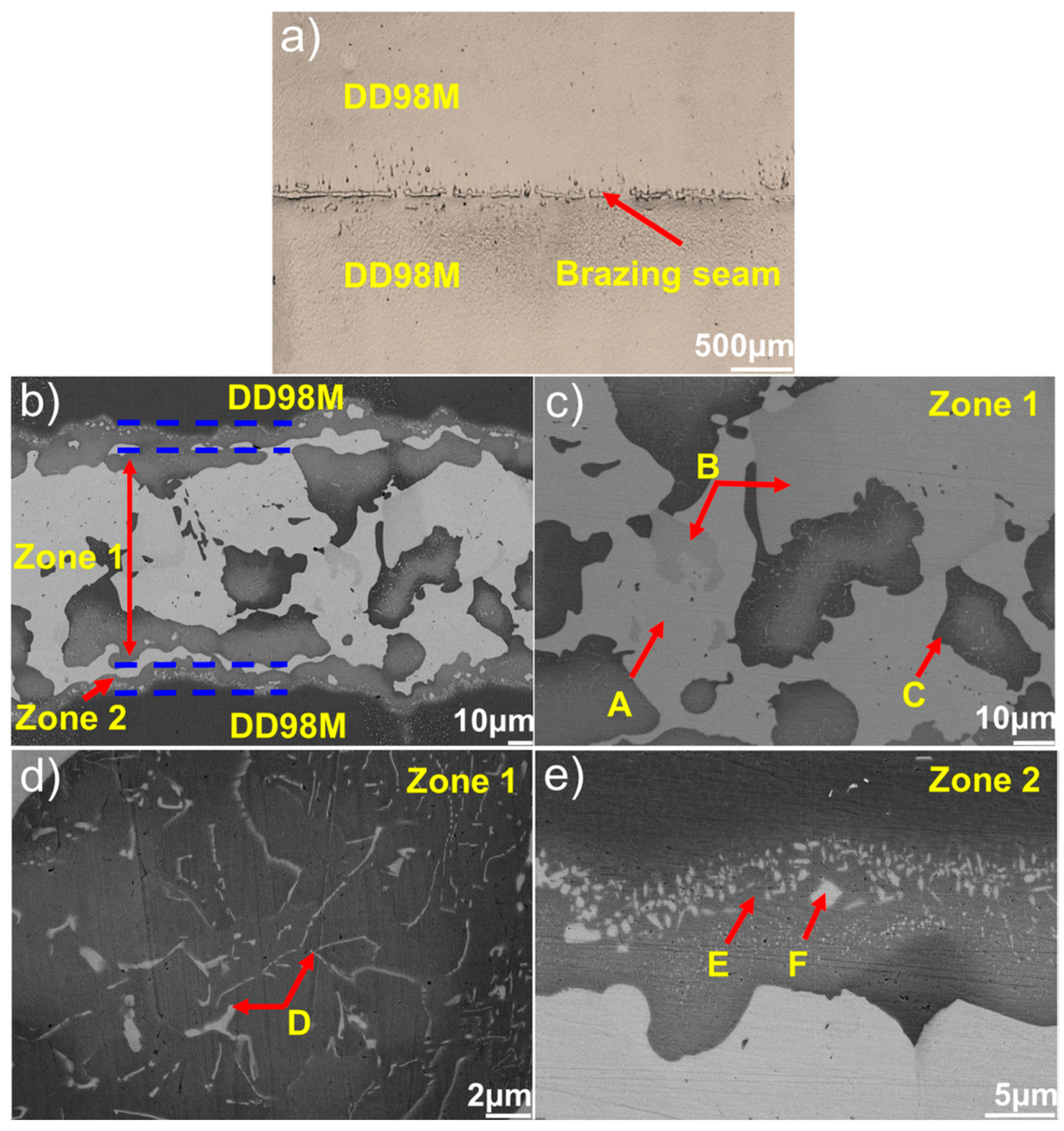
| Position | Al | Si | Ti | Cr | Co | Ni | Mo | Pd | Ta | W | Phase |
|---|---|---|---|---|---|---|---|---|---|---|---|
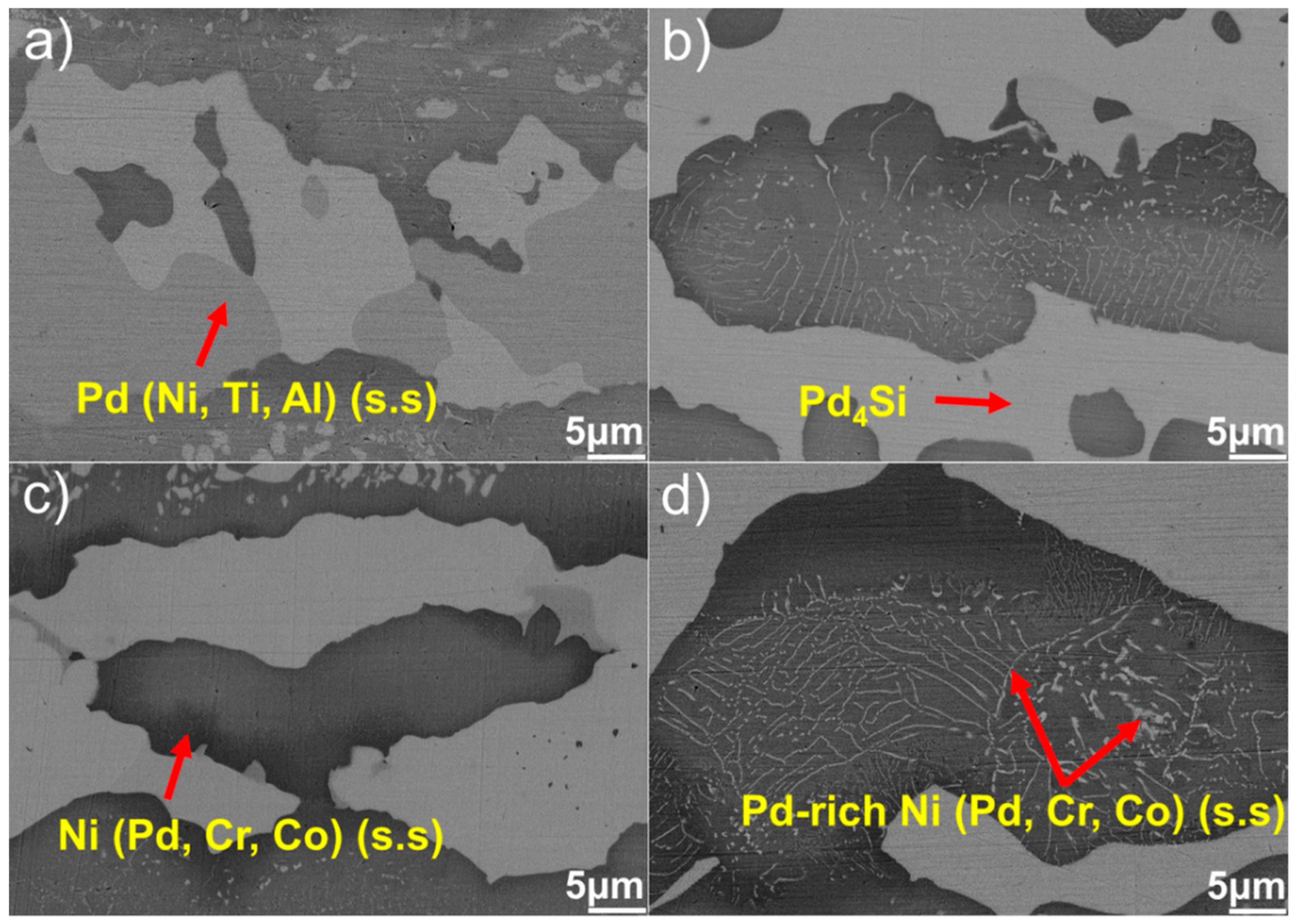
| A | 0.9 | 19.9 | 0.2 | 0.0 | 0.0 | 1.8 | 0.1 | 76.9 | 0.1 | 0.1 | Pd4Si |
| B | 8.1 | 1.9 | 11.5 | 1.6 | 0.3 | 21.4 | 0.2 | 52.3 | 2.7 | 0.0 | Pd (Ni, Ti, Al) (s.s) |
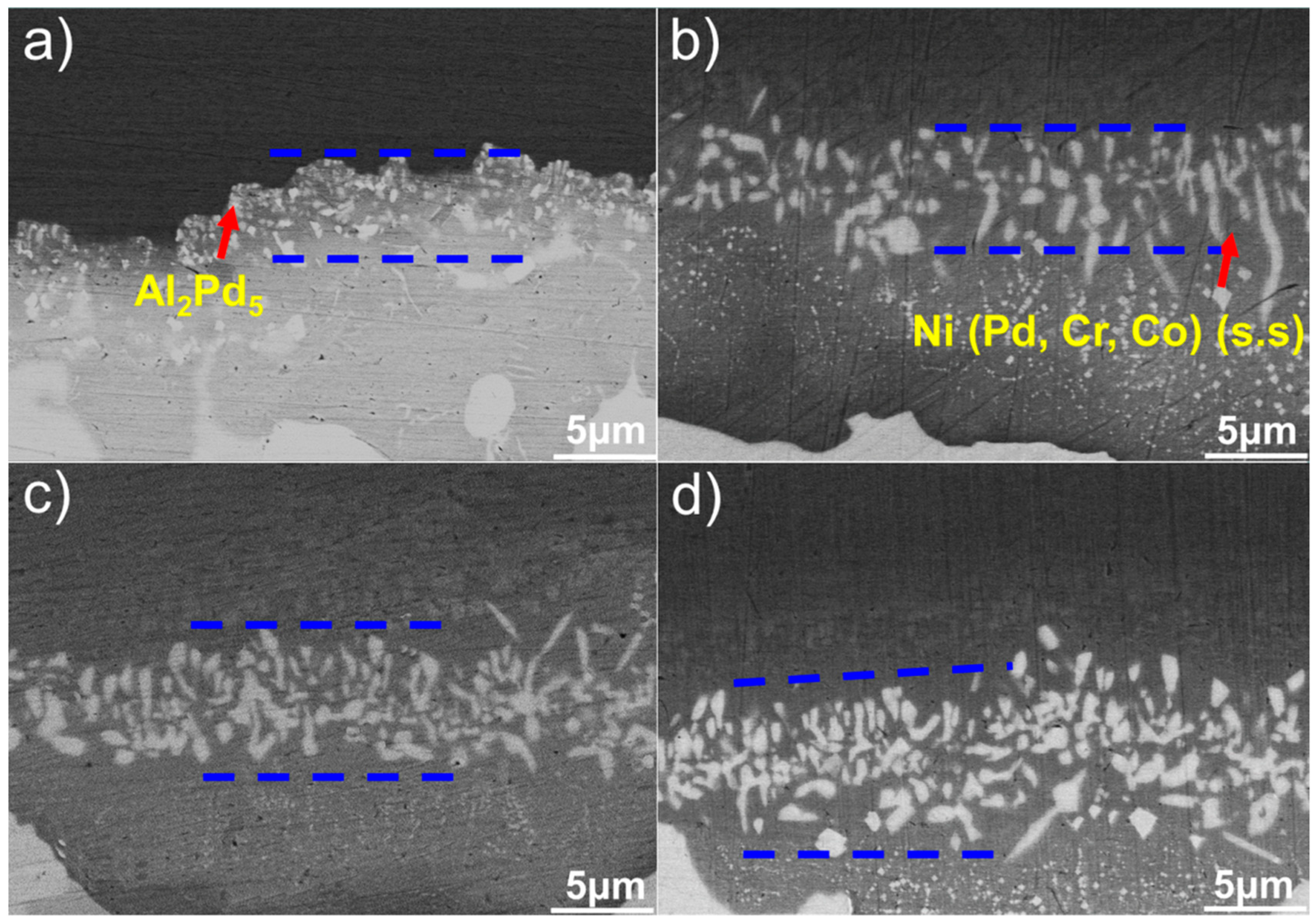
| C | 0.6 | 4.0 | 1.2 | 11.1 | 8.0 | 57.3 | 0.5 | 14.8 | 1.5 | 1.0 | Ni (Pd, Cr, Co) (s.s) |
| D | 2.2 | 1.6 | 1.4 | 8.9 | 7.7 | 48.1 | 1.2 | 26.1 | 1.1 | 1.7 | Pd-rich Ni (Pd, Cr, Co) (s.s) |
| E | 0.7 | 1.8 | 0.5 | 12.2 | 10.5 | 63.2 | 1.2 | 5.7 | 2.3 | 1.9 | Ni (Cr, Co, Pd) (s.s) |
| F | 23.5 | 4.1 | 0.5 | 1.1 | 0.5 | 6.2 | 0.0 | 63.8 | 0.1 | 0.2 | Al2Pd5 |
© 2019 by the authors. Licensee MDPI, Basel, Switzerland. This article is an open access article distributed under the terms and conditions of the Creative Commons Attribution (CC BY) license (http://creativecommons.org/licenses/by/4.0/).
Share and Cite
Qin, C.; Xu, H.; Zhou, Z.; He, Y.; Lu, C.; Gao, K.; Zheng, W.; Yang, J.; Wang, D.; Sun, Y.; et al. Microstructure and Mechanical Performance of the DD98M-DD98M Single Crystal Superalloy Joints Brazed Using a Pd-Si Composite Filler. Metals 2019, 9, 1001. https://doi.org/10.3390/met9091001
Qin C, Xu H, Zhou Z, He Y, Lu C, Gao K, Zheng W, Yang J, Wang D, Sun Y, et al. Microstructure and Mechanical Performance of the DD98M-DD98M Single Crystal Superalloy Joints Brazed Using a Pd-Si Composite Filler. Metals. 2019; 9(9):1001. https://doi.org/10.3390/met9091001
Chicago/Turabian StyleQin, Chunjie, Haitao Xu, Zhengqiang Zhou, Yanming He, Chuanyang Lu, Ke Gao, Wenjian Zheng, Jianguo Yang, Donghong Wang, Yuan Sun, and et al. 2019. "Microstructure and Mechanical Performance of the DD98M-DD98M Single Crystal Superalloy Joints Brazed Using a Pd-Si Composite Filler" Metals 9, no. 9: 1001. https://doi.org/10.3390/met9091001
APA StyleQin, C., Xu, H., Zhou, Z., He, Y., Lu, C., Gao, K., Zheng, W., Yang, J., Wang, D., Sun, Y., & Gao, Z. (2019). Microstructure and Mechanical Performance of the DD98M-DD98M Single Crystal Superalloy Joints Brazed Using a Pd-Si Composite Filler. Metals, 9(9), 1001. https://doi.org/10.3390/met9091001