Abstract
In the present work, an evaluation of the volume fraction of austenite in austempered ductile iron (ADI) is presented by means of three different methods. Experimental tests were conducted on ADI samples after different austempering conditions and contained different volume fractions of the phase components in the metallic matrix (ferrite plates + austenite). A comparison of the volume fraction of austenite was carried out by metallographic magnetic methods using a variable field, as well as X-ray quantitative phase analysis. The main purpose of this work is to show the effectiveness of the proposed magnetic method for estimating the volume fraction of austenite in ADI cast iron. It is evident that the new method in which variable magnetic fields are used to quantify the phase composition exhibits very high accuracy within the second stage of the austempering transformation, in which the metallic matrix consists of ferrite plates and high-carbon austenite. Finally, this research shows that within the first and third stages the estimation of the volume fraction of the austenite is hampered by errors resulting from the presence of martensite (first stage) and carbide phases (third stage).
1. Introduction
Austempered ductile iron (ADI) belongs to a family of high-strength spheroidal graphite cast iron (SGI) that is heat-treated; i.e., by austenitization and subsequent austempering. ADI selection is a cost-effective solution for various applications, including automobile manufacturing; construction and mining equipment; railroad equipment; agricultural equipment; gears and crankshafts; and brackets, among others [1,2,3]. The microstructure of ADI consists of spheroidal graphite nodules embedded in a metallic matrix of high-carbon austenite plus ferrite plates. The ADI microstructure depends on several technological parameters connected to the SGI production process (chemical composition, liquid metal treatment, spheroidization and inoculation, superheating time, and temperature of liquid metal), including the implemented heat-treatments.
The conventional heat-treatment process for ADI production starts with austenitization to transform the initial metallic matrix microstructure to austenite. During the austempering stage, the austenite decomposes into ferrite plates and high-carbon austenite [2]. The number of graphite nodules, their shape and distribution, the number and morphology of the ferrite plates, and finally the high-carbon austenite determine the final properties of ADI castings.
In the literature, numerous articles have been published on ADI, particularly on the structure formation [4,5,6]; the kinetics of the austenitizing and austempering processes [1,2,3,7,8,9]; the effect of alloying elements [10,11,12,13]; mechanical and fatigue properties [14,15,16,17]; machinability [18]; applications [19]; and numerical simulations [9,20,21]. The literature review shows that, besides the precipitation of ferrite plates, austenite plays an important role in shaping the properties of ADI castings.
According to Nili-Ahmadabadi [22], austenite provides toughness and ductility, whereas ferrite plates promote high strength in ADI. The completion of the austempering transformation is determined by the carbon enrichment of the austenite (among other things). Carbon stabilization of the austenite eliminates the martensitic transformation upon cooling to room temperature (as reported by Bamberger [2]). The growth of ferrite plates during austempering increases the carbon content in the austenite before starting the bainite reaction. In addition to this, carbon enrichment in the austenite leads to an increase in the austenite lattice parameter, which makes it difficult for precise estimations of the austenite fraction by means of XRD to be made. Tyrała [23] stated that although a series of methods for determining phase composition are available, none can be considered to be fully universal.
In the analysis of the suitability of various methods (particularly in the assessment of the fraction of high-carbon austenite in ADI cast iron), the speed and accuracy of such measurements should also be taken into account. This is of great importance, particularly during the production of ADI under industrial conditions. In this work, the magnetic method was employed to assess the volume fraction of austenite during the austempering process. The results of the quantitative and qualitative changes in the austempering process are discussed and compared with the following results of this research: metallographic, X-ray quantitative phase analysis, and hardness measurements. This work is a continuation of a previous work connected with phase composition analysis using a variable magnetic field [23].
In his work, Tyrała [23] showed that a Fe-Cu alloy exhibits a linear relationship between the magnetic dissipation of the alloy and the volume fraction of the phase component with the ferromagnetic properties. The above result is the basis for the new method in which variable magnetic fields are used to quantify the phase composition. This method is universal for two-phase alloys when the magnetic dispersion coefficient of the two phases is different. It can be particularly useful for assessing the contribution of the austenite and residual austenite in heat-treated iron-carbon alloys. Despite the limitations in its application, the following important advantages should be emphasized: Good accuracy in the evaluation, easy and fast measurements, and low research costs. Due to its easy and fast way to carry out measurements, it can be used not only in metallurgical laboratories but also in production lines for non-destructive control of heat-treated components during the production of ADI.
2. Materials and Methods
The evaluation of the volume fraction of the phase components was made in a series of samples with 20 × 20 mm dimensions from spheroidal graphite cast iron subjected to heat treating with different austempering times. The samples were taken from a “Y-shaped” casting (according to the ASTM A 536-84 standard) with a wall thickness of 25 mm and a chemical composition (wt %) of 3.45% C, 2.55% Si, 1.35% Cu, 0.98% Ni, 0.15% Mo, 0.05% Mg, 0.04% Cr, 0.02% P, and 0.005% S.
The heat treatment was carried out in a POK72 chamber resistance furnace and a backflow resistance furnace. The conditions for the heat treatment were chosen on the basis of dilatometric examinations made with a DI105-type dilatometer with a capacitive displacement sensor. The results from dilatometry are shown in Figure 1 and Figure 2. For the sample marked as II, ferritizing annealing was carried out at 740 °C for 180 min. The samples marked III to XIV were austenitized at 880 °C for 120 min and austempered for various isothermal times at 380 °C. The heat treatment conditions are summarized in Table 1.
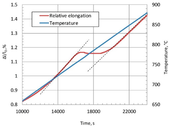
Figure 1.
Relative dimensional changes Δl/l0 recorded during heating at Vn = 1 °C/min. in spheroidal graphite cast iron.
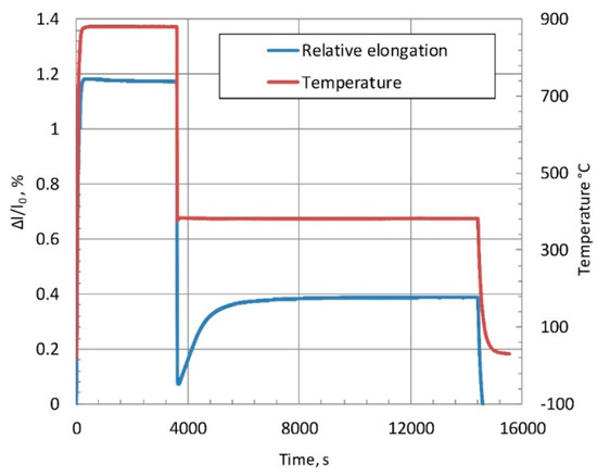
Figure 2.
Relative dimensional changes Δl/l0 in % recorded during the austenitization and austempering processes in spheroidal graphite cast iron.

Table 1.
Heat treatment conditions.
The measurements of the volume fraction of austenite at different austempering times were made by metallographic magnetic methods using a variable field and X-ray quantitative phase analysis. The quantitative assessment by means of the metallographic method was carried out using a Leica MEF-4M optical microscope. The microstructural components were revealed by sample etching with 4% nital. A Leica QWin automatic imaging software enabled quantitative microstructural analyses and was employed to assess the volume fraction of phases.
3. Results
Figure 3 shows the microstructures of samples I, II, III, VI, IX, XI, XII, and XIV. In samples I to XIV; the volumetric fraction of graphite, VG; and for samples VI, IX, XI, XII, and XIV—the volume fraction of austenite, VA were both determined by metallographic methods. Moreover, determinations of volume fraction of austenite were carried out by magnetic means. In this case, the apparatus used for determining the magnetic scatter ks of the ADI cast iron was plugged to a power network with a frequency of f = 50 Hz through a control autotransformer enabling the change of transmission coil voltage Un. Figure 4 schematically shows an examined sample in the measurement system, which acts as a magnetic core. When determining the magnetic scatter ks, the following boundary conditions were assumed: ks = 0—no scattering; ks = 1—magnetic scatter is complete [23].
where:
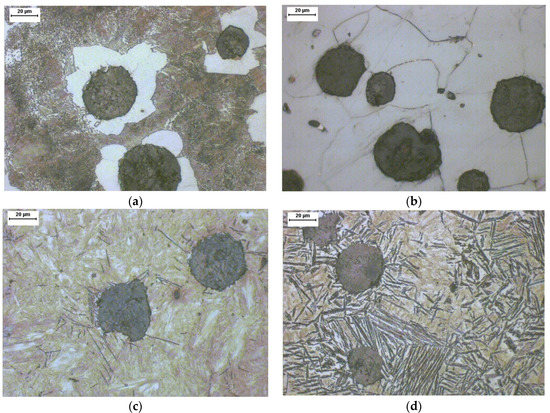
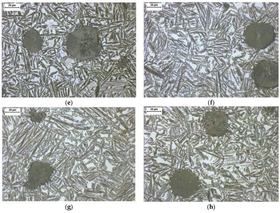
Figure 3.
Microstructures of samples: (a)—I; (b)—II; (c)—III; (d)—VI; (e)—IX; (f)—XI; (g)—XII; and (h)—XIV. Nital etched, mag. 500×.
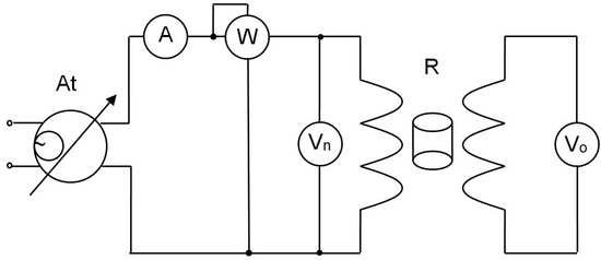
Figure 4.
Diagram of experimental system: At—autotransformer; Vn and Vo—electromagnetic voltmeters; A—electromagnetic ammeter; R—tested sample [23].
- Un—voltage in the transmitting coil [mV],
- Uo—voltage in the receiving coil [mV],
- a—apparatus constant (a = 2.280),
- ks—magnetic scatter.
The volumetric fraction of austenite in ADI can be calculated from Equation (2) [23]:
where:
- kA = kG = 0.775—magnetic scattering coefficient of austenite and graphite,
- kF = kM = 0.120—magnetic scattering coefficient for ferrite and martensite,
- VG—graphite volume fraction determined by metallographic methods in %,
- VA—volume fraction of austenite in %.
The X-ray examinations were carried out using a Philips X-ray diffractometer with a PW1710 goniometer. Identification and assessment of the volume fraction of the phase constituents were identified from diffractograms within an angular range of 30–105° using CoKα-series X-ray filtering. The volume fraction of austenite was determined by a direct Averbach–Cohen comparison. APD (a computer program from Philips) was used to interpret the diffraction image. Similar to the metallographic method, measurements were made for samples VI, IX, XI, XII, and XIV. Figure 5 shows the diffraction pattern of the sample XI.
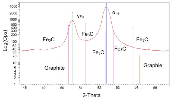
Figure 5.
Diffraction pattern of sample XI.
The resultant volume fractions of the graphite VG, austenite VA, including Brinell’s hardness results are summarized in Table 2.
Table 2.
Results of volume fractions of graphite and austenite using metallographic, variable magnetic field, and X-ray diffraction along with Brinell’s hardness.
4. Discussion
The austempering process is preceded by austenitization, which aims to produce a homogeneous distribution of austenite containing around 0.8% carbon. After austenitizing and cooling the castings at speeds above the critical one, they are kept in the temperature range below the austenitic transformation and above the martensite start temperatures (which ultimately leads to an austempering transformation). The selection of the right austempering time enables achieving an optimal, purely ausferritic metallic matrix (that is, a mixture of ferrite plates and high-carbon stable austenite). The volume fraction of the phases included in the isothermal-tempered spheroidal graphite cast iron is a function of several variables and depends on the initial cast iron microstructure, the graphite size and shape, the chemical composition, the austenitization temperature and time, and the temperature and time of the austempering.
An as-cast spheroidal graphite cast iron with a pearlitic-ferritic metallic matrix is shown in Figure 3a. The components of the cast iron microstructure after ferritizing annealing (shown in Figure 3b) are only ferrite and graphite. The qualitative and quantitative microstructural determinations for the above samples can be carried out by metallographic means with unequivocal accuracy. Yet, difficulties in estimating the volume fraction of the phase constituents in the tested ADI samples appear when, besides graphite, there is austenite along with martensite and ferrite in the microstructure. In terms of the phases present in the ADI samples (marked with numbers III and VI), the diverse microstructures are shown in Figure 3c,d. Determining the volume fraction of the existing phases is a rather difficult task by microstructural image analysis due to the lack of a clear determination of the phase interfaces. In this first stage of austempering (up to 60 min), the qualitative and quantitative changes in the microstructure univocally reflect changes in the magnetic scattering and hardness (as shown in Figure 6). The small number of ferrite plates visible in Figure 3c confirms the start of the ausferritic transformation (i.e., nucleation and growth of ferrite with a simultaneous carbon enrichment of the surrounding austenite). Carbon promotes austenite stabilizing, thus increasing its fraction at the expense of a reduction in the fraction of martensite.
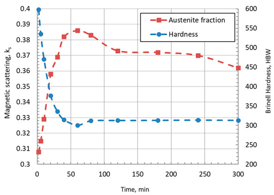
Figure 6.
Changes in magnetic scattering ks and hardness of austempered ductile iron (ADI) as a function of austempering time.
The sample IX (whose microstructure is shown in Figure 3e) consists solely of graphite, ferrite, and austenite. The decreasing value of magnetic scattering after 60 min of austempering is attributed to the growth of ferrite plates. After 120 min, ferrite growth is negligibly small, and the austenite reaches its total (maximum) stability. This result is confirmed by dilatometric studies (Figure 2), where inhibition of sample lengthening is observed. In the literature (13), this time is referred to as the first stage of the austempering transformation. The second stage, in which there is a two-phase austenitic-ferritic metallic matrix, covers a period of 120 to 180 min. The drop in magnetic scattering after about 180 min of austempering (as seen in Figure 6) should be identified with the onset of the bainitic transformation and, thus, the beginning of the third stage of the austempering.
The volume fraction of austenite determined by different methods (i.e., metallographic, variable magnetic field, and X-ray diffraction) for the examined samples is shown in Figure 7.
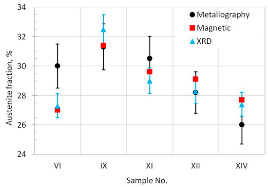
Figure 7.
Volume fraction of austenite determined by different methods.
The graphite and ferrite fractions determined by metallographic methods and the value of the magnetic scattering for Sample II were used to determine the magnetic scattering coefficient for ferrite kF = 0.120. In sample VI, the volume fraction of the austenite was determined assuming the same value of the magnetic scattering coefficient for ferrite and martensite due to the large number of phases. The above simplification is undoubtedly the cause of error in the assessment of volume fractions; however, this error decreases with decreasing contents of martensite. A clearly divergent result from the metallographic method may result from an incomplete martensite disclosure. A comparison of the results of austenite fraction attained by the variable magnetic, metallographic, and X-ray methods for the samples IX, XI, and XII should be considered compatible, as they all fall within the error limits of these methods. The result obtained in sample XIV (with an overstated austenite fraction) is a consequence of the precipitation of carbide phases in the third stage of transformation. The results of diffraction studies XRD indicate a relatively small complication in clearly determining the fraction of carbide phases.
5. Conclusions
The following conclusions regarding the usefulness of the proposed magnetic method for estimating the volume fraction of austenite in the ADI cast iron during austempering can be summarized as follows:
- -
- The volume fraction of austenite in ADI can be unambiguously determined in the second stage of the austempering transformation;
- -
- The estimation of the volume fraction of austenite during the first stage of the austempering transformation is hampered by an error arising from the different magnetic scattering factors related to the ferrite and martensite phases. During the third stage of the transformation, the volume fraction of the austenite is overestimated due to the presence of carbide phases.
Author Contributions
Conceptualization, E.T., M.G., M.K.; methodology, E.T. and M.G.; investigation, E.T., M.G., A.M.; writing—original draft preparation, E.T., M.G.; and writing—review and editing, M.G., M.K. and H.F.L.
Funding
This research received no external funding.
Conflicts of Interest
The authors declare no conflict of interest.
References
- Nelson, E. Why ADI? Four applications where ADI is the material of choice and process considerations. In Proceedings of the Ductile Iron Society 2016 World Conference on ADI, Atlanta, GA, USA, 27–28 October 2016; pp. 1–6. [Google Scholar]
- Bamberger, M. Encyclopedia of Iron, Steel, Their Alloy, 5th ed.; Taylor and Francis: New York, NY, USA, 2016; pp. 196–216. [Google Scholar]
- Tanaka, Y.; Kage, H. Development and Application of Austempered Spheroidal Graphite Cast Iron. Mater. Trans. JIM 1992, 33, 543–557. [Google Scholar] [CrossRef]
- Donnini, R.; Fabrizi, A.; Bonollo, F.; Zanardi, F.; Angella, G. Assessment of the microstructure evolution of an austempered ductile iron during austempering process through strain hardening analysis. Met. Mater. Int. 2017, 23, 855–864. [Google Scholar] [CrossRef]
- Fras, E.; Górny, M.; Tyrała, E.; Lopez, H. Effect of nodule count on austenitising and austempering kinetics of ductile iron castings and mechanical properties of thin walled iron castings. Mater. Sci. Technol. 2012, 28, 1391–1396. [Google Scholar] [CrossRef]
- Górny, M.; Tyrała, E.; López, H. Effect of Copper and Nickel on the Transformation Kinetics of Austempered Ductile Iron. J. Mater. Eng. Perform. 2014, 23, 3505–3510. [Google Scholar] [CrossRef]
- Cekic, O.E.; Sidjanin, L.; Rajnovic, D.; Balos, S. Austempering kinetics of Cu-Ni alloyed austempered Ductile Iron. Met. Mater. Int. 2014, 20, 1131–1138. [Google Scholar] [CrossRef]
- Arab, N. Investigation to production machinable austempered ductile iron (MADI). J. Am. Sci. 2011, 7, 49–52. [Google Scholar]
- Boccardo, A.; Dardati, M.; Celentano, D.J.; Godoy, L.A.; Górny, M.; Tyrała, E. Numerical Simulation of Austempering Heat Treatment of a Ductile Cast Iron. Metall. Mater. Trans. B 2016, 47, 566–575. [Google Scholar] [CrossRef]
- Bosnjak, B.; Radulović, B.; Pop-Tonev, K.; Asanovic, V. Influence of Microalloying and Heat Treatment on the Kinetics of Bainitic Reaction in Austempered Ductile Iron. J. Mater. Eng. Perform. 2001, 10, 203–211. [Google Scholar] [CrossRef]
- Darwish, N.; Elliott, R. Austempering of low manganese ductile irons. Part 1 Processing window. Mater. Sci. Technol. 1993, 9, 572–585. [Google Scholar] [CrossRef]
- Darwish, N.; Elliott, R. Austempering of low manganese ductile irons. Part 2 Influence of austenitising temperature. Mater. Sci. Technol. 1993, 9, 586–602. [Google Scholar] [CrossRef]
- Darwish, N.; Elliott, R. Austempering of low manganese ductile irons Part 3 Variation of mechanical properties with heat treatment conditions. Mater. Sci. Technol. 1993, 9, 882–889. [Google Scholar] [CrossRef]
- Mallia, J.; Grech, M. Effect of silicon content on impact properties of austempered ductile iron. Mater. Sci. Technol. 1997, 13, 408–414. [Google Scholar] [CrossRef]
- Keough, J.R.; Hayrynen, K.L. Wear Properties of Austempered Ductile Irons. AFS Trans. 2005, 113, 803–812. [Google Scholar]
- Biswas, S.; Monroe, C.; Prucha, T. Use of Published Experimental Results to Validate Approaches to Gray and Ductile Iron Mechanical Properties Prediction. Int. J. Met. 2017, 11, 656–674. [Google Scholar] [CrossRef]
- Zanardi, F. Fatigue properties and machinability of ADI. Metall. Ital. 2005, 10, 27–32. [Google Scholar]
- Druschitz, A.P.; Fitzgerald, D.C. MADITM: Introducing a New, Machinable, Austempered Ductile Iron; SAE Technical Paper Series 0831; SAE International: Warrendale, PA, USA, 2003; pp. 1–9. [Google Scholar]
- Keough, J.R.; Hayrynen, K.L.; Pioszak, G.L. Designing with austempered ductile iron (ADI). AFS Trans. 2010, 10, 1–15. [Google Scholar]
- Boccardo, A.D.; Dardati, P.M.; Godoy, L.A.; Celentano, D.J. Sensitivity of Austempering Heat Treatment of Ductile Irons to Changes in Process Parameters. Met. Mater. Trans. A 2018, 49, 1522–1536. [Google Scholar] [CrossRef]
- Kapturkiewicz, W.; Fraś, E.; Burbelko, A.; Burbelko, A. Computer simulation of the austenitizing process in cast iron with pearlitic matrix. Mater. Sci. Eng. A 2005, 413, 352–357. [Google Scholar] [CrossRef]
- Nili-Ahmadabadi, M.; Shirazi, H. Austempered Ductile Cast Iron: Bainitic Transformation. In Encyclopedia of Iron, Steel, and Their Alloys; CRC Press: Boca Raton, FL, USA, 2015; pp. 217–230. [Google Scholar]
- Tyrała, E. Phase Composition Using a Variable Magnetic Field. ISIJ Int. 2014, 54, 700–703. [Google Scholar] [CrossRef][Green Version]


© 2019 by the authors. Licensee MDPI, Basel, Switzerland. This article is an open access article distributed under the terms and conditions of the Creative Commons Attribution (CC BY) license (http://creativecommons.org/licenses/by/4.0/).