Article

Analytical Modeling of the Mixed-Mode Growth and Dissolution of Precipitates in a Finite System

1
Department of Mining, Metallurgy and Materials Engineering, Aluminum Research Center–REGAL, Laval University, 1065, ave de la Médecine, Québec, QC G1V 0A6, Canada
2
Linamar Corporation—The Center, 700 Woodlawn Road West, Guelph, ON N1K 1G4, Canada
3
Rio Tinto, Arvida Research and Development Centre, 1955, Mellon Blvd, Saguenay, QC G7S 4K8, Canada
4
Linamar Montupet Light Metal Division, 3, rue de Nogent, 60290 Laigneville, France
*
Author to whom correspondence should be addressed.
Metals 2019, 9(8), 889; https://doi.org/10.3390/met9080889
Submission received: 25 July 2019 / Revised: 8 August 2019 / Accepted: 12 August 2019 / Published: 14 August 2019
(This article belongs to the Special Issue Phase Transformations in Aluminium Alloys)

Abstract

:
In this paper, a novel analytical modeling of the growth and dissolution of precipitates in substitutional alloys is presented. This model uses an existing solution for the shape-preserved growth of ellipsoidal precipitates in the mixed-mode regime, which takes into account the interfacial mobility of the precipitate. The dissolution model is developed by neglecting the transient term in the mass conservation equation, keeping the convective term. It is shown that such an approach yields the so-called reversed-growth approximation. A time discretization procedure is proposed to take into account the evolution of the solute concentration in the matrix as the phase transformation progresses. The model is applied to calculate the evolution of the radius of spherical θ-Al2Cu precipitates in an Al rich matrix at two different temperatures, for which growth or dissolution occurs. A comparison of the model is made, with the results obtained using the numerical solver DICTRA. The very good agreement obtained for cases where the interfacial mobility is very high indicates that the time discretization procedure is accurate.

1. Introduction

The mathematical modelling of the growth and dissolution of precipitates in metals is of prime importance in the development of predictive tools dedicated to the optimization of heat treatments and material properties. For that purpose, numerical models are perhaps the most flexible and accurate tools, but their low computational efficiency and unresolved theoretical problems associated to the thermodynamics and kinetics of the interface limits their use. As a result, analytical models are preferred for the simulation of precipitate growth and dissolution in commercial software applications dedicated to precipitation kinetics. The evolution equations used today in these applications differ by the approximations made to simulate multicomponent diffusion efficiently. PrecipiCal uses the growth model proposed by Jou et al. [1], who used the stationary field approximation to solve the mass conservation equation. This approach neglects, however, the moving boundary problem and cannot provide a very good solution when the growth velocity is high. The evolution equations used in MatCalc were developed according to the thermodynamic extremal principle [2]. This method assumes that the matrix phase has a uniform composition, which has a major drawback of neglecting the effect of interfacial concentrations. The application packages TC-PRISMA and PanPrecipitation use different models to cover a wide range of cases. The simplified model used in these applications is the one proposed by Morral and Purdy [3], which is based on the stationary field assumption. As an advanced model, TC-PRISMA and PanPrecipitation use the solution of the quasi-stationary mass conservation equation proposed by Chen et al. [4], who applied a binary exact solution to the multicomponent case, assuming that the diffusion length of each specie depends only on the specie’s own supersaturation. This assumption was proven to have some limitations and inaccuracies by Guillemot and Gandin [5], who provided a more exact treatment of the quasi-stationary mass conservation problem in a multicomponent system.
For the modelling of dissolution, mathematical treatments are curiously not well developed since, according to Aaron et al. [6], there is no exact solution available for spherical precipitates. This statement was written in 1970 but has been recently acknowledged by Guo et al. [7]. The available dissolution models, therefore, have been based, up to now, on one of the frequently used approximate solutions.
The models mentioned above assume that local equilibrium prevails at the interface. This implies that thermodynamic constraints must be applied at the interface to obtain the solution. However, as pointed out in the user guide of TC-PRISMA [8], an advanced multicomponent model can be time consuming and can fail to find a solution to the flux-balance equations. To add robustness and time efficiency to the calculation scheme, one may further simplify the models by replacing the interfacial compositions by nuclei and matrix compositions, as is suggested in the TC-PRISMA user guide.
The role of the interface kinetics is taken into account via the interfacial mobility. The software applications mentioned above have included the interfacial mobility in their growth kinetics models to simulate situations where the interfacial mobility is limited for some reason. This variable is introduced according to its energy dissipative effect, which reduces the available driving force. This is correct in principle, but the calculation scheme allowing the computation of interfacial compositions is not clear, especially if this is combined with the alternative tie-lines of the phase diagram or the average phase compositions. Moreover, the dissipative effect is proportional to the interfacial velocity, and this certainly does not help the computational efficiency if the thermodynamics constraints are not relaxed at the interface. The regime during which the growth velocity is controlled by both the diffusion of the elements in the matrix, and the mobility of the interface is called the mixed-mode. This is the general case, since one can say that growth kinetics is always in the mixed-mode, with the diffusion-controlled and interface-controlled regimes being just the two extreme regimes. Larouche [9] provided an exact analytical solution for the quasi-stationary mixed-mode growth of an ellipsoidal precipitate in a binary system. Naseri et al. [10] later extended the mixed-mode solution to calculate the growth of a precipitate containing more than one specie diffusing in the matrix. These authors showed that the search for alternative tie-lines is useless for the calculation of interfacial compositions, since the interface is not at equilibrium during growth.
Considering that the mixed-mode approach encompasses all previous diffusion-controlled models and gives the possibility to calculate more precisely interfacial compositions with better computational efficiency, we decided to find a solution for the dissolution of precipitates and to adapt the quasi-stationary mixed-mode solution to a finite system. This will give the possibility to use these solutions for the simulation of growth and dissolution of precipitates in a given volume. The mathematical treatment will be applied on a binary system, to focus the scope on the dissolution problem and on the time discretization procedure.

2. Dissolution in the Quasi-Stationary Regime of an Ellipsoidal Precipitate

As mentioned in the introduction, analytical solutions for the mass conservation equation are not available for the dissolution of a spherical or an ellipsoidal precipitate. The only solution available is for the planar dissolution, and the reason why no solution was found for the other geometries must be clarified first. Let us suppose that during a phase transformation process, a reference frame moves with the interface, so that the latter remains at the coordinate x′ = 0, while the atoms move as a whole in a direction perpendicular to the interface. The mass conservation equation in this frame of reference is [11]:
( D c ) = v c + c t
where D is the coefficient of diffusion, c is the molar concentration, t is the time, and v is the molar-average velocity of the atoms. The solution of the quasi-stationary regime is obtained by setting c / t equal to zero. For the situation depicted in Figure 1, the growth of the precipitate requires that the atoms have a negative velocity in the moving reference frame, opposite to the velocity of the interface.
For constant and uniform material properties, the following equation is then obtained for the planar interface:
D 2 c x 2 = v c x .
Suppose now that a new frame of reference is defined such that it travels with the atoms, at the same average-molar velocity. The matrix–precipitate system is, therefore, immobile in this frame of reference while the interface is moving. Let x be the coordinates in this frame. The relationship between the two systems of coordinates depends on the direction along which the interface is moving. It follows that for a precipitate growing at the expense of the matrix (growth), we have the following relationship:
Growth:
x = x v t .
For a matrix growing at the expense of the precipitate (dissolution), we have this relationship:
Dissolution:
x = x + v t .
Since v = x / t , when the precipitate is growing and the interface is moving to the right (atoms moving to the left in the x′ system of coordinates), Equation (2) can then be rewritten as:
Growth:
D 2 c x 2 = x t c x .
However, when the precipitate is dissolving, v = x / t , and Equation (2) is expressed as follows:
Dissolution:
D 2 c x 2 = x t c x .
For the dissolution of a spherical particle, the following equation is then obtained:
D r 2 r ( r 2 c r ) = r t c r .
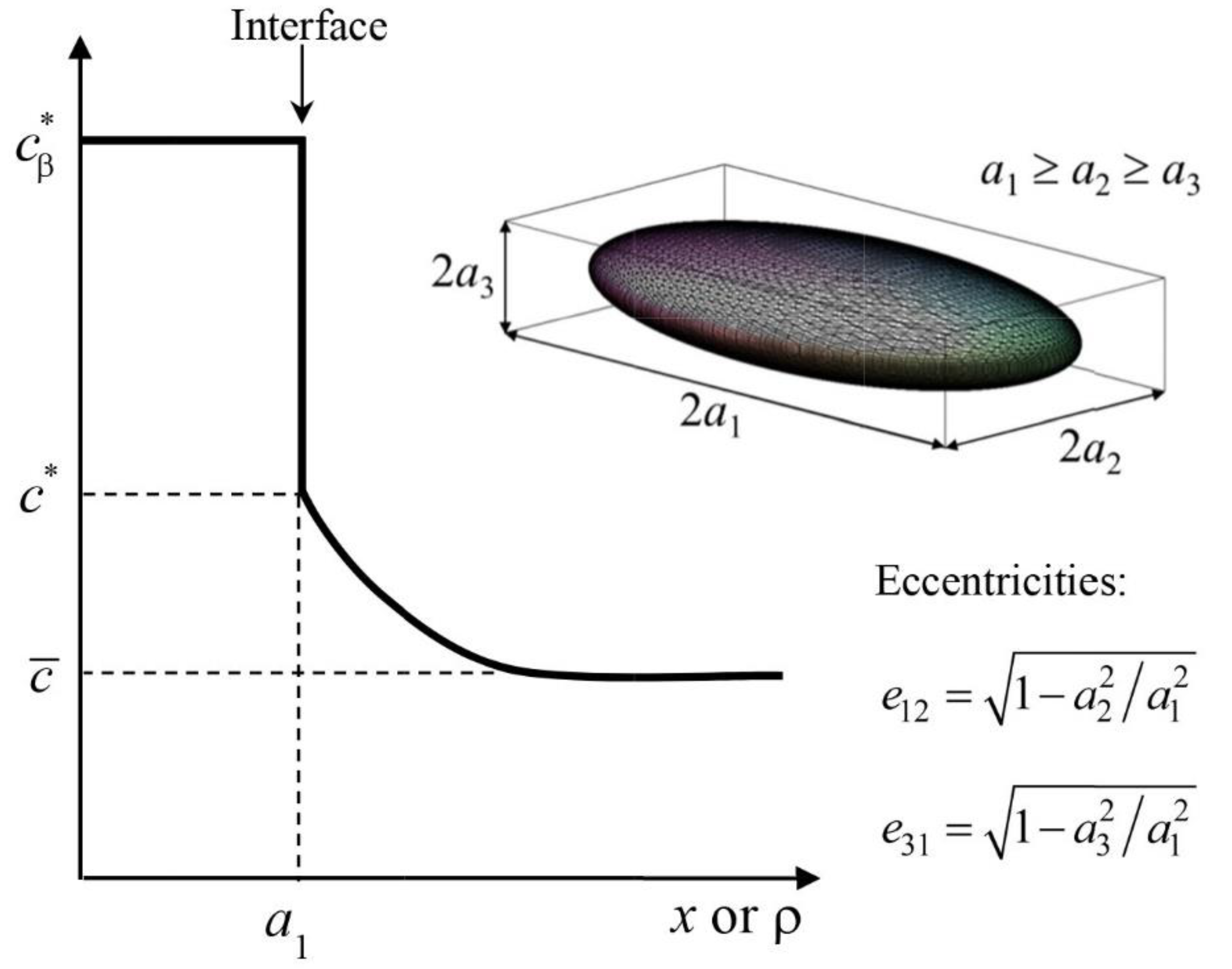
Solving Equation (7) yields the so-called reversed-growth approximate solution, which was first provided by Aaron et al. [6] for the spherical particle. These authors did not mention that their solution was in fact obtained from Equation (7), but one can easily show that their expression for the solute concentration profile is in fact a solution of that mass conservation equation. The reversed growth solution is not exact because the initial conditions cannot be met, having neglected the transient term ∂c/∂t in Equation (1). Thus, if an exact analytical solution of the dissolving spherical particle could be found, perhaps solving Equation (1) instead of the standard Fick’s second law could be an option. According to Aaron et al. [6] and Guo et al. [7], the reversed-growth approximation is not the best method to calculate the dissolution rates. However, one can acknowledge from the comparison made in [6] between the dissolution rates calculated by the recommended method (invariant size-approximation) and the reversed-growth approximation, that the dissolution times calculated by both methods are close one to each other, especially in the limit of small supersaturation. The reversed-growth approximation has an advantage that we will use hereafter. The advantage is that the limiting effect of the interfacial mobility can be taken into account easily with the reversed-growth solution. Therefore, we will use the reversed-growth solution of the mass conservation equation applied to an ellipsoidal precipitate, which will be found using the solution procedure outlined by Larouche [9] for the mixed-mode growth of an ellipsoidal precipitate evolving with constant eccentricities. This solution procedure is detailed in the Appendix A. The different parameters of the problem are defined in Figure 2.
The reversed-growth solution can be expressed as:
c * c ¯ c β * c * = a 1 3 1 e 12 2 1 e 31 2 2 D τ exp ( a 1 2 4 D τ ) a 1 [ ( ρ 2 e 12 2 a 1 2 ) 1 / 2 ( ρ 2 e 31 2 a 1 2 ) 1 / 2 exp ( ρ 2 4 D τ ) ] d ρ
where τ is the time remaining before complete dissolution. The molar fraction of the matrix at the interface, c*, is expressed as:
c * = c e q exp ( V m a 1 2 c β * M R T k d τ 3 / 2 + 2 V m γ 1 c β * R T a 1 ) = c e q * exp ( V m a 1 2 c β * M R T k d τ 3 / 2 )
where M is the interfacial mobility, R is the gas constant, T is the absolute temperature, Vm is the molar volume of the precipitate, c e q is the solubility of the solute element according to the phase diagram, (planar interface), and γ1 is the interfacial energy at the tip of the precipitate (the smallest radius of the curvature). The parameter kd is the interface migration coefficient for dissolution, which is expressed as:
k d = 1 2 υ c a c
where ac is the semi-axis length of the precipitate at the end of the mixed mode regime, and υc is the dissolution velocity occurring during the final interfacial controlled regime. For a dilute binary system, this velocity can be estimated with the following equation [9]:
υ c = M R T V m c β * ln ( c ¯ c e q * ) .
Since c e q * > c ¯ for a dissolving precipitate, the calculated value of υc is negative.

3. Application of the Dissolution Model

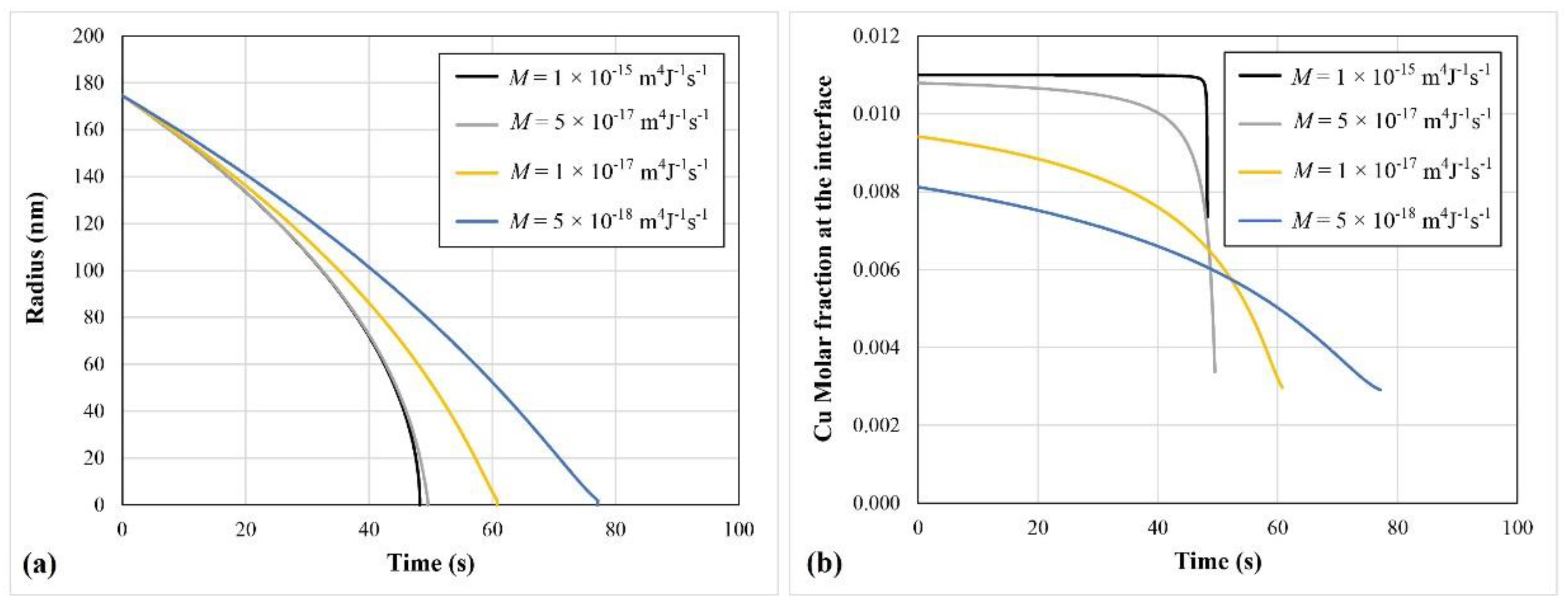
For a dissolution problem, one must consider that a pre-existing precipitate has grown to a certain size and then, suddenly, the conditions changed such that the solubility of the matrix rose above the nominal composition of the system. To illustrate such a case, we will consider a spherical θ-Al2Cu precipitate having an initial size of 175 nm surrounded by an infinite Al rich matrix having a Cu molar fraction c ¯ = 0.00285. At a temperature of 730 K, the solubility of the matrix is c e q = 0.011 according to the Al–Cu phase diagram. We will neglect the interfacial energy and assume that ac = 2 nm and Vm = 1 × 10⁻⁵ m³/mol. A constant coefficient of diffusion of 1.0 × 10⁻¹⁴ m2 s−1 will be assumed. Figure 3a presents the time evolution of the radius of the precipitate for different values of the interfacial mobility, and Figure 3b presents the corresponding evolution of the Cu molar fraction at the interface. It is clear that if the interfacial mobility (M) is larger than 1 × 10⁻¹⁵ m4 J−1 s−1, one can consider that dissolution occurs essentially in the diffusion-controlled regime. This results from the fact that c * is, most of the time, equal to c e q with a high interfacial mobility.

4. Growth and Dissolution in a Finite System

The analytical solutions proposed for the mixed-mode regime were developed for one particle evolving in an infinite system. These solutions were based on the fact that the molar fraction c ¯ is constant, as well as the temperature and material properties. In the following, we will consider that the temperature remains constant but, due to the finite size of the system, c ¯ will vary with time. The coefficient of diffusion can also be assumed to vary with c ¯ . Numerical time discretization is required in such a case to calculate the evolution of the precipitate. The latter can be approximated using the first two terms of the Taylor expansion of the explicit (unknown) solution. The value of a1 at time t + Δt can then be approximated with the following equation:
a 1 ( t + Δ t ) a 1 ( t ) + a 1 t | c ¯ ( t ) Δ t .
At each time t, the value of the interface velocity a / t | c ¯ ( t ) is first calculated with the current value of c ¯ . If the time step is small enough, Equation (12) will give an accurate estimation of the updated size of the precipitate, assuming that the variation of c ¯ is negligible during this small time step. The interface velocity in the mixed-mode regime can be evaluated from the slopes of a1(t), evaluated at time t and t + Δt, using Equations (8) and (9) to evaluate the values of a1 when the precipitate is dissolving. For growth, the following equations must be used [9]:
c ¯ c * c β * c * = a 1 3 1 e 12 2 1 e 13 2 2 D t exp ( a 1 2 4 D t ) a 1 [ ( ρ 2 e 12 2 a 1 2 ) 1 / 2 ( ρ 2 e 13 2 a 1 2 ) 1 / 2 exp ( ρ 2 4 D t ) ] d ρ
where
c * = c e q * exp ( V m a 1 2 c β M R T k g t 3 / 2 ) .
The interface migration coefficient for growth (kg) is expressed as:
k g = 1 2 υ c a c .
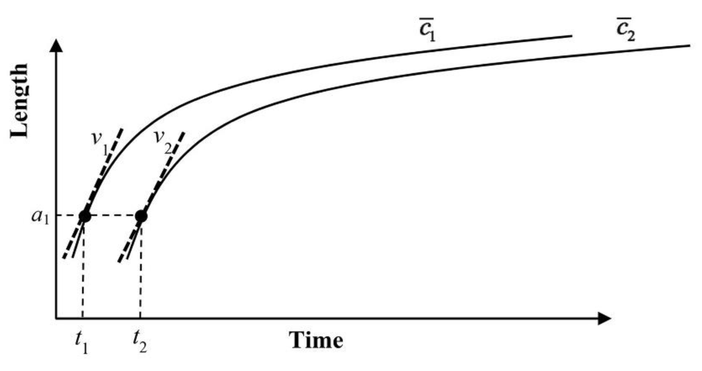
Time discretization can be done by setting a time step and calculating the size of the precipitate at time t1 and t2 = t1 + Δt with Equations (8) and (9) or Equations (13) and (14). Alternatively, one can define the time step according to a predefined Δ c ¯ , and calculate the corresponding times for the current value of a1. Figure 4 presents schematically the evolution of a1 during growth, as calculated with two values of c ¯ , namely c ¯ 1 and c ¯ 2 = c ¯ 1 + Δ c ¯ . Notice that Δ c ¯ < 0 for growth. The interface velocity can be evaluated by first, choosing a value of Δ c ¯ that is sufficiently small in comparison with the current value of c ¯ to make the estimation accurate. With these two values of c ¯ , one calculates with Equation (13) the values of t1 and t2 with the current value of a1. The time step Δt will then be equal to t2t1. For dissolution, Equation (8) must be solved to obtain the values of τ1 and τ2. The interface velocities can be estimated from the slopes evaluated at time t1 and t2 (τ1 and τ2 for dissolution). Since c ¯ changes continuously during the time interval, one can use the average value of the two velocities, v1 and v2. The following expression can then be used to calculate the interface velocity appearing in Equation (12):
a t | c ¯ ( t ) ν 1 + ν 2 2 .
Other techniques of time discretization are possible. The advantage of the technique proposed above is that one can easily find a time step adjusted to Δ c ¯ , irrespective of the magnitude of the interface velocity. Thus, when the system is close to reaching equilibrium, a very small Δ c ¯ will result in a very large Δt.
Once a 1 ( t + Δ t ) is obtained from Equation (12), the value of c ¯ can then be updated for the next step.
It should be noted that since the value of c ¯ changes during the transformation in a finite system, the maximum growth velocity υ c is not constant, so the interface migration coefficient is not constant, as well. Therefore, these parameters must be updated at each time step.

5. Application of the Model

To make a direct comparison with DICTRA [12], we will consider the growth and dissolution of spherical θ-Al2Cu precipitates in an Al rich matrix. A one-size distribution of precipitates will be assumed to simplify the comparison. For that matter, we will consider that the system contains a given number density (Nβ) of identical precipitates. If c0 is the nominal solute molar fraction of the system, the value of c ¯ will be calculated at each time step with the following expression:
c ¯ = c 0 g β c β 1 g β
where gβ is the volume fraction of precipitates. Notice that this expression neglects the impact of the concentration gradients near the precipitates in the estimation of the average molar fraction in the matrix, as no distinction is made between this parameter and the molar fraction at infinity. This is acceptable only if the distance between the precipitates is large in comparison to the diffusion length. For a one-size distribution of ellipsoidal precipitates, gβ is simply given by
g β = N β 4 3 π a 1 3 1 e 12 2 1 e 31 2 .
For spherical precipitates, e12 and e31 are equal to zero. Table 1 presents the parameters describing the system in which the precipitates are evolving. For the DICTRA simulation, the matrix is an FCC (the name of the phase in the DICTRA software application). A1 phase having an external radius matching the number density of the approximate finite size model. All calculations were performed with DICTRA version 2016a using the TCAL5 [13] and MOBAL1 [14] databases.
In addition, we require some equilibrium parameters, which are shown in Table 2. The equilibrium data were obtained by using Thermo-Calc [12] and the TCAL5 [13] database.
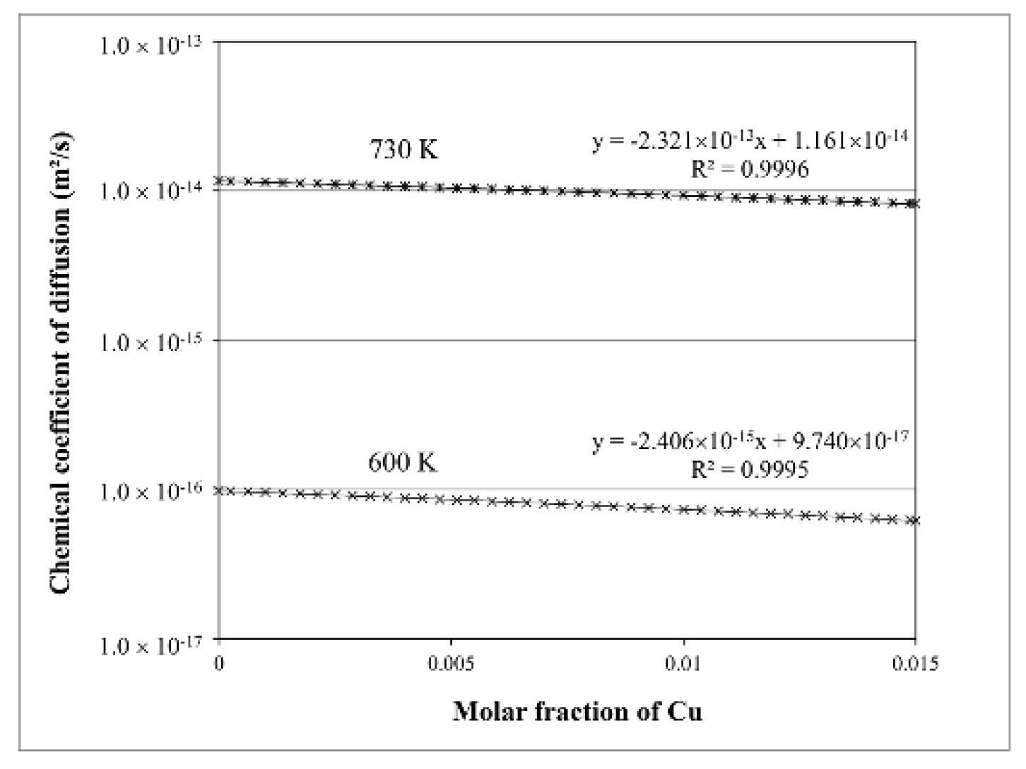
The coefficient of diffusion was assumed to vary with the amount of copper in the matrix. DICTRA takes this variation into account at each grid node. In our model, the coefficient of diffusion was considered to be a global variable changing with the molar fraction c ¯ . Figure 5 shows the variation of the coefficient of diffusion of Cu in an Al rich matrix when the concentration of Cu is less than 1.5 at% at 600 K and 730 K. The plot for T = 730 K will be used later for the dissolution of the precipitates. According to this figure, the growth of the precipitates occurs simultaneously with a rise of the coefficient of diffusion. Therefore, the accuracy of the calculation will increase by using a variable coefficient of diffusion.
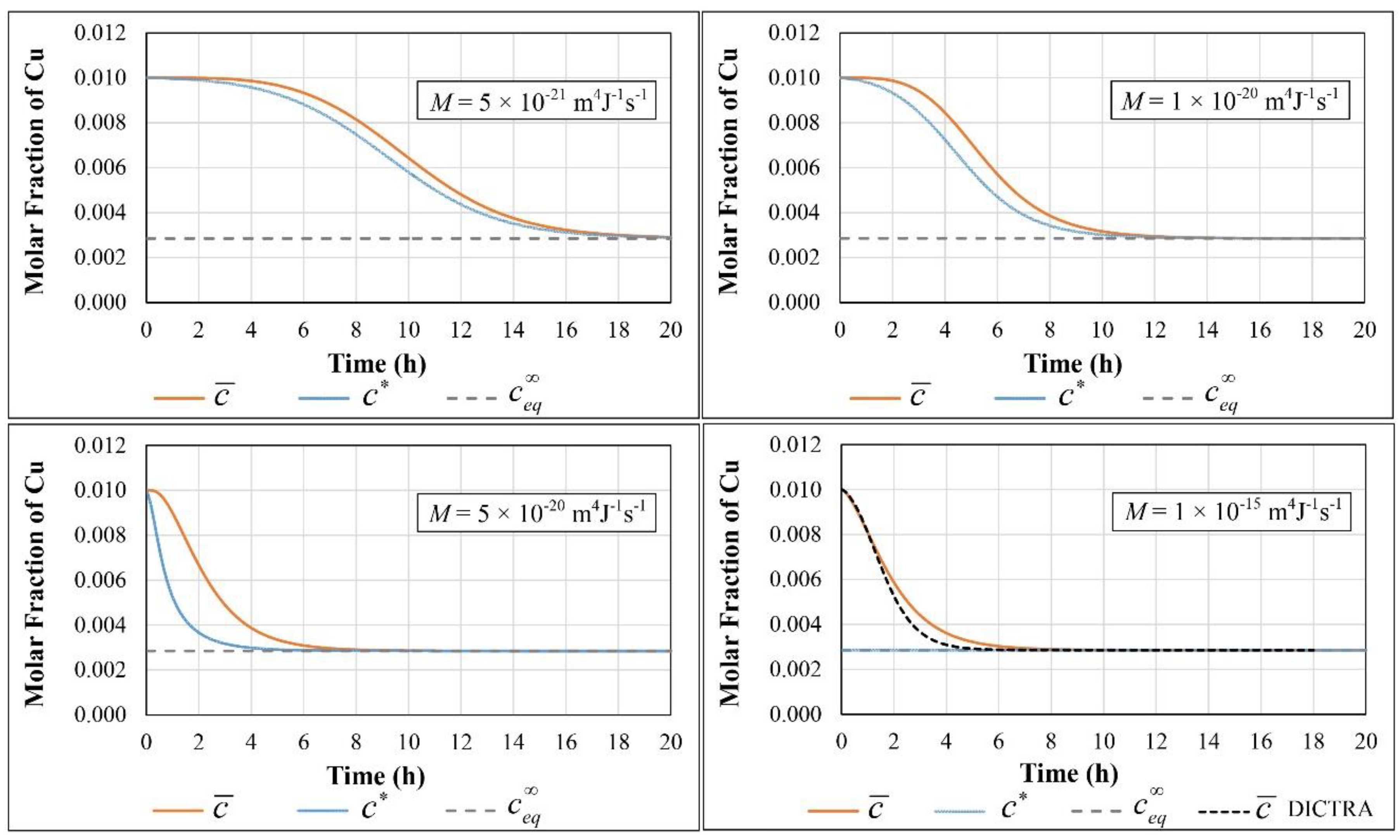
Figure 6 shows the evolution of the radius of the θ-Al2Cu precipitates calculated with different values of the interfacial mobility, while Figure 7 presents the corresponding evolutions of c ¯ and c * .
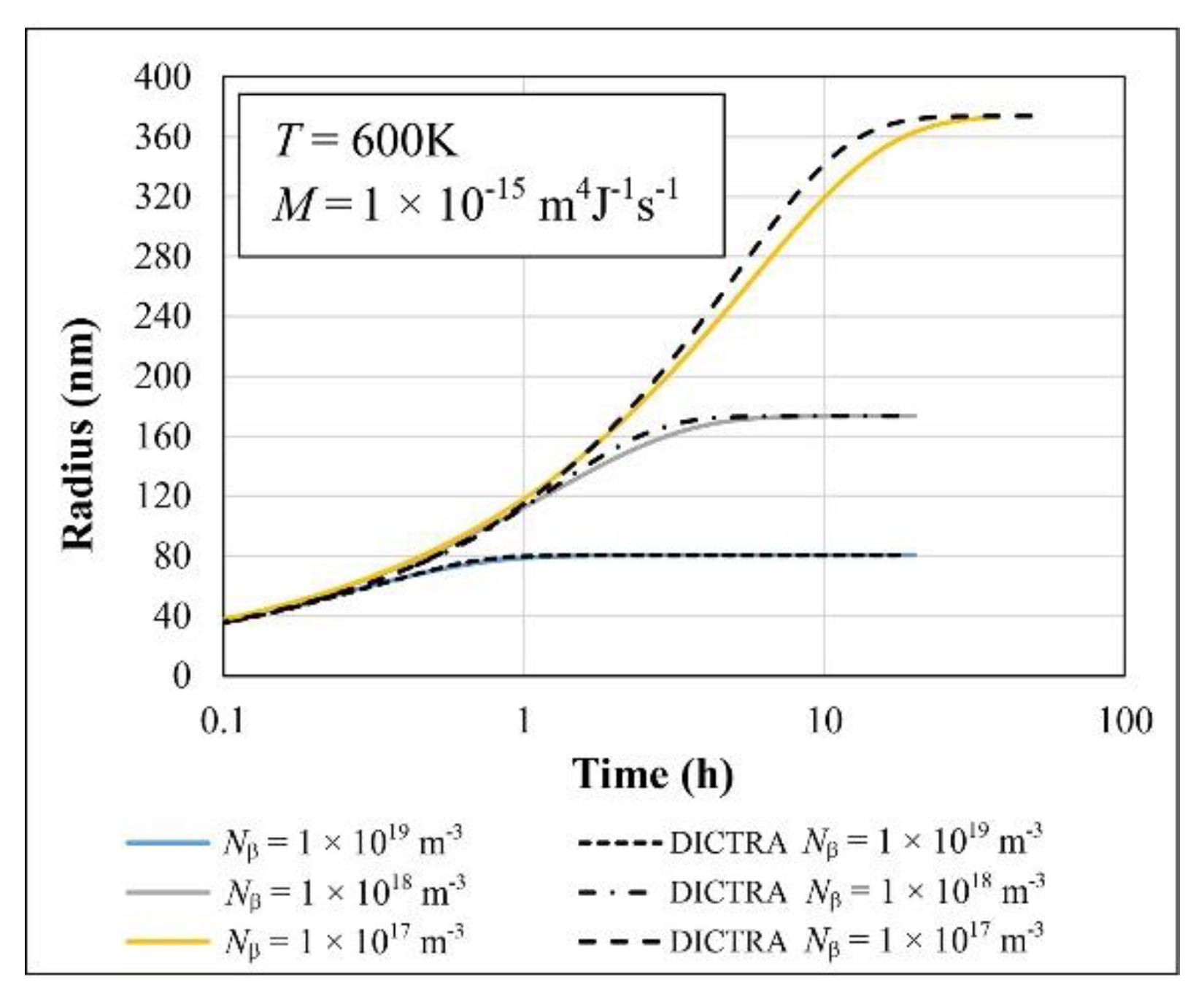
As far as the comparison with DICTRA is concerned, one can say that the case with M = 1.0 × 10⁻¹⁵ m4/J/s gives a very close agreement with the DICTRA simulation. With such a high interfacial mobility, we have c * c e q , so one can consider that the growth regime is essentially diffusion-controlled in this circumstance. It is worthwhile to mention that the value of ac has a negligible impact on the results when the interfacial mobility is such that growth or dissolution can be assumed to be diffusion-controlled. This stems from the fact that when the kinetics of phase transformation are diffusion controlled, the k-parameter is assumed to be very high, which is consistent with a diffusion-controlled regime starting almost at time zero. The DICTRA curves start to deviate slightly from the high M case for a time > 1 h. To understand the origin of this deviation, one may consider the impact of the number density in the size evolution. Figure 8 presents the evolution of the radius (on a logarithmic scale) as computed with three different values of the number density. One can see that the discrepancy between the DICTRA curves and the model is reduced as the number density increases. If the discrepancy was caused by our time discretization procedure or by not taking into account the concentration gradient in the matrix to calculate c ¯ , then one would have observed the discrepancy to increase as the number density increased. Indeed, as the number density increases, the model moves away from the ideal case where the matrix is infinite. A closer look of the DICTRA results can explain this discrepancy. Figure 9 presents the solute concentration profile in front of the precipitate as calculated by DICTRA for the three values of the number density. These curves reveal that the calculated solute concentration profiles near the interface differ from the ideal case where a smooth and gradual increase of the solute molar fraction would be obtained in front of the interface up to the limit of the system. This is likely the result of the numerical procedure of DICTRA, which introduces the discrepancy between the two methods. Notice that increasing the node density in the matrix domain in the DICTRA model did not change the results. However, selecting a planar geometry instead of the spherical one removes the secondary minimum in the solute concentration profile in the vicinity of the interface and reduces the large gap existing between c e q imposed at the interface and the value of the solute molar fraction obtained at the first node in front of the interface. We did not try, however, numerical parameters differing from those set by default in DICTRA.
We, therefore, consider our model to be very accurate for evaluating theoretical growth rates, especially for cases including a strongly dissipative precipitate–matrix interface (low mobility).
From the final state of the previous system, one can imagine that the temperature is then suddenly raised to 730 K, which activates the dissolution of the precipitates. The parameters describing the dissolution of θ-Al2Cu precipitates in this system are presented in Table 3. According to the Al–Cu phase diagram [15], the solubility of copper in the FCC aluminum matrix at 730 K is 1.1 at%. Since the nominal concentration of copper in the studied system is 1.0 at%, it is expected that keeping the system at 730 K will make the second phase to dissolve completely.
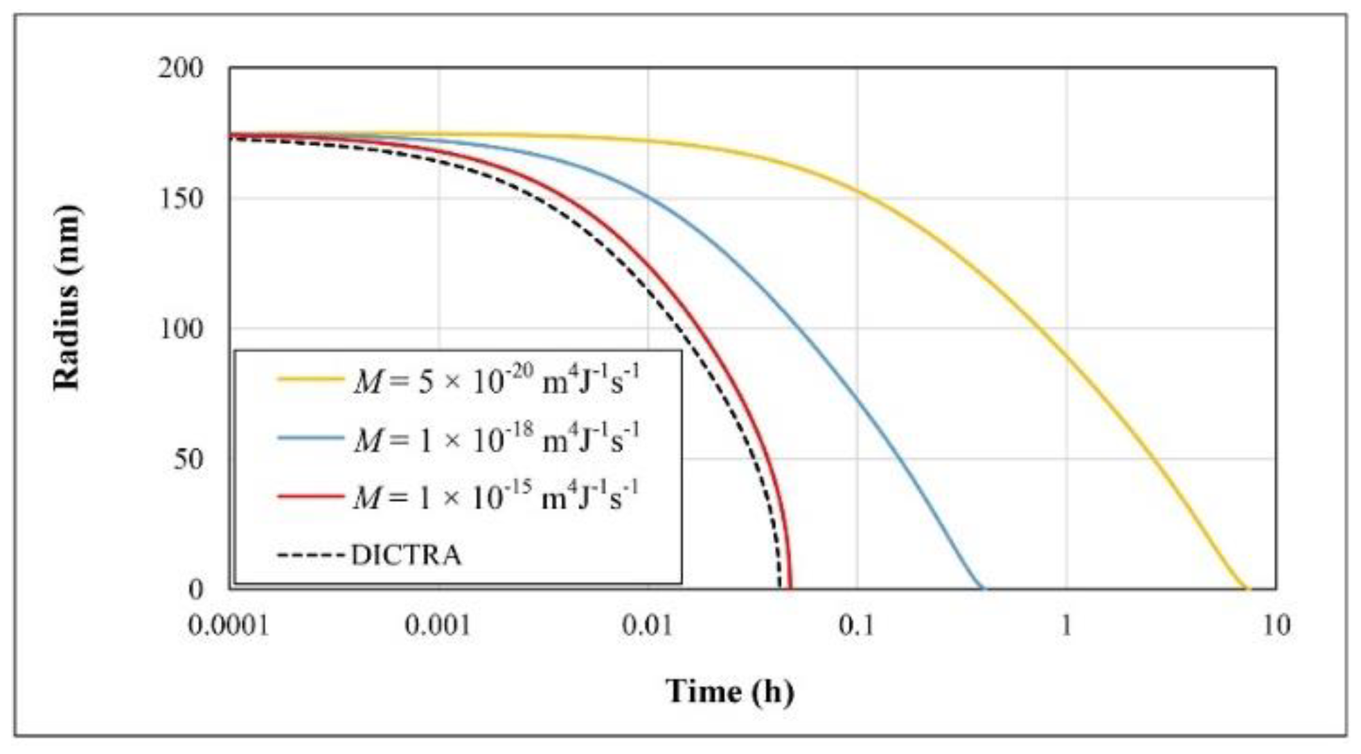
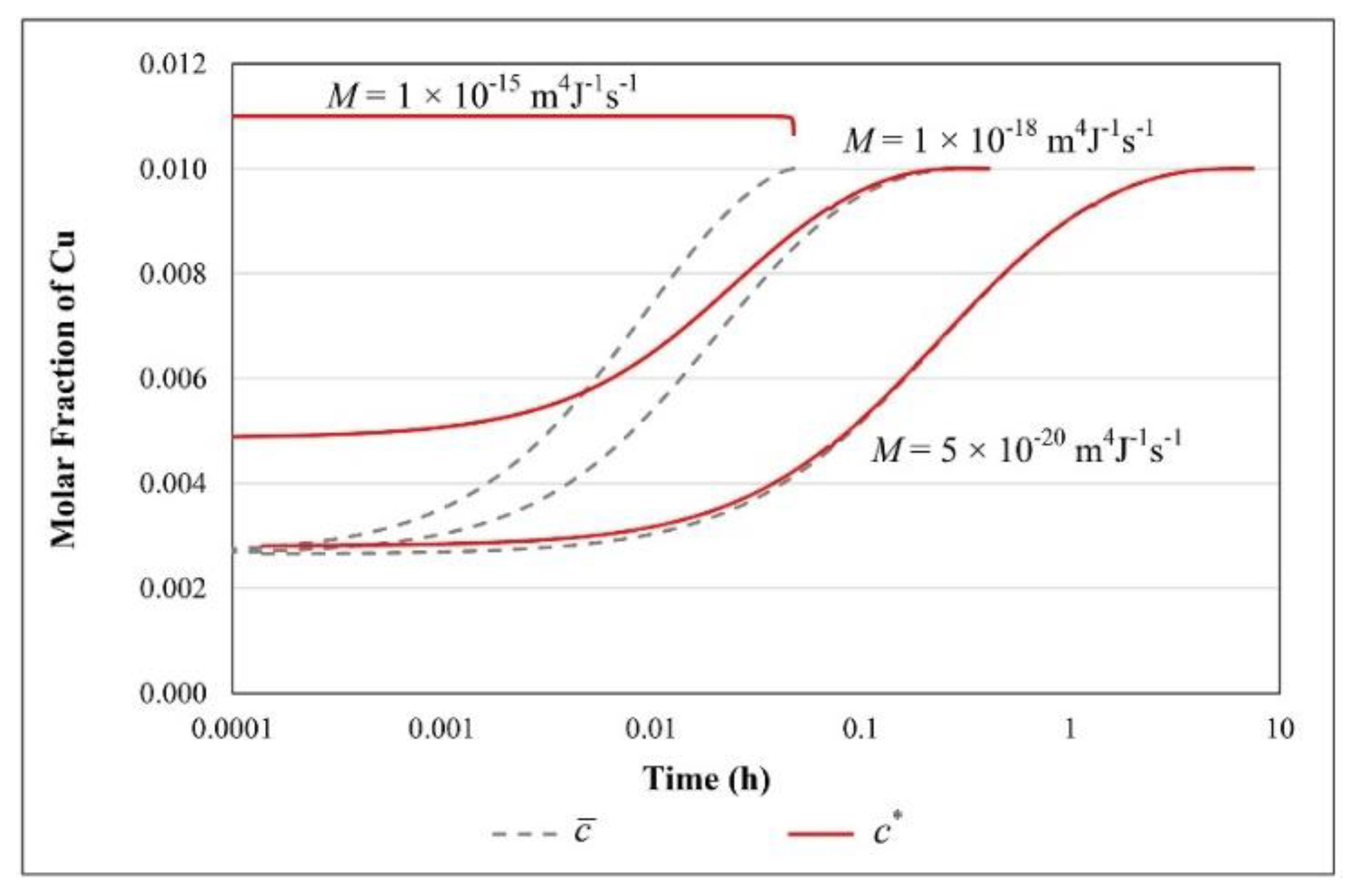
The time evolution of the radius of the precipitates is plotted in Figure 10 for different values of the interfacial mobility. The agreement between the dissolution with a high interfacial mobility and the DICTRA simulation is very good. A maximum time delay of 19 s between the two models was obtained at the end of the dissolution process. For the lower interfacial mobility cases, the evolution of c ¯ and c * are very close one to each other, as is shown in Figure 11 for M = 5.0 × 10⁻²⁰ m4 J−1 s−1. For such a low interfacial mobility, one can assume that dissolution is essentially an interface controlled process, while for growth, it is clearly a mixed-mode process (see Figure 7). For a high mobility case, one can see that c * c e q = 0.011 during almost the entire process.

6. Discussion

The mixed-mode model, which was originally developed for the growth of one particle in an infinite matrix, has been adapted for the growth and dissolution in a finite system, making the model suitable for comparison with a software application like DICTRA. The agreement with the DICTRA simulations for cases where the interfacial mobility is very high is such that one can acknowledge the accuracy of the time discretization procedure described above. Although some authors stated that the reverse-growth approximation is not the best method to calculate the dissolution rate of a precipitate, our results show that the agreement between our reversed-growth model and the DICTRA fully transient solution is in fact excellent, and could only be improved if the analytical procedure accounted for the transient term in the mass conservation equation. The diffusion-controlled reversed-growth solution ignores the transient period, during which the dissolution rate is accelerated by the very high concentration gradients existing at the start. This high concentration gradient makes the DICTRA simulation able to predict a slightly faster dissolution. This error is not very significant considering that the dissolution rate is likely limited by the interfacial mobility at the beginning because of the too steep concentration gradients required to have equilibrium at the interface. A possible option to improve the agreement between DICTRA and our model is to consider the dissolution of a smaller precipitate surrounded by its steady-state concentration field, the latter being composed of atoms liberated by the precipitate having the nominal size. This is an option that may be of interest for comparison purposes.

7. Conclusion

Since the quasi-stationary solution of the precipitation is based on the assumption that the concentration of the solute in the matrix is constant, theoretically it cannot be used when a variation of the concentration happens in the system. In this contribution, the previous mixed-mode model [9] has been modified in two ways. First, a reversed-growth approximate solution was developed for the dissolution in the mixed-mode regime. Second, a time discretization technique was proposed, which makes possible to model the evolution of precipitates inside a finite matrix. The model was validated with DICTRA for the diffusion controlled-regime and can be applied to the fully diffusion-controlled, as well as the fully interface controlled, regime.

Author Contributions

Investigation and methodology, T.N. and D.L.; Supervision, D.L., F.B., D.M. and R.M.; Writing–original draft, T.N. and D.L.; Writing–review & editing, D.L. and D.M.

Funding

This research was funded by the Natural Sciences and Engineering Research Council of Canada (NSERC), grant number RDCPJ 468550–54814, and also by the companies Montupet and Rio Tinto Arvida.

Acknowledgments

The authors would like to thank Pierre Heugue from Laval University and X. Grant Chen from the University of Québec at Chicoutimi for fruitful discussions on the topic of precipitation kinetics.

Conflicts of Interest

The authors declare no conflict of interest.

Appendix A

Reversed-Growth Solution of the Mass Conservation Equation in the Mixed-Mode Regime for an Ellipsoidal Precipitate

The reversed-growth model for dissolution is found, as discussed in the main text, by considering the following quasi-stationary mass conservation equation:
D 2 c = c d r d t
where r is the vector position of a point located on the interface. For a dissolving ellipsoidal particle, we will assume that the dissolution occurs with constant eccentricities. Considering the Eulerian set of ellipsoidal coordinates (ρ, μ, ν), we are, therefore, searching for a solution for which the concentration of the species will be uniform on ellipsoids ρ = constant, so that c = c ( ρ , t ) . Under these circumstances, Equation (A1) becomes:
D h ρ h μ h ν ρ ( h μ h ν h ρ c ρ ) = c d r d t
where hρ, hµ, and hν are the metric coefficients. The convective term will be rearranged by using a new set of coordinates (ξ, η, ζ) moving with the interface. Introducing the interface migration coefficient kd, one can propose the following substitutions:
ξ = ρ / k d τ 1 / 2
η = μ / k d τ 1 / 2
ζ = ν / k d τ 1 / 2
H 2 = h 2 / k d τ 1 / 2 = a 1 2 a 3 2 k d τ 1 / 2
H 3 = h 3 / k d τ 1 / 2 = a 1 2 a 2 2 k d τ 1 / 2
with
τ = t f t
where t is the time, and t f is the time where complete dissolution occurs. The parameters h2 and h3 are the semi-focal distances of the ellipsoid. Equations (A6) and (A7) are necessary for a shape preserved dissolution.
Since ξ is a curvilinear coordinate and that c = 0 along the unit vectors η ^ and ζ ^ , we have
c d r d t = ξ c ξ ξ ξ t = 1 h ξ 2 c ξ ξ t = 1 h ξ 2 c ξ ξ τ .
The mass conservation equation can now be rewritten as
D h ρ h μ h ν ρ ( h μ h ν h ρ c ρ ) = 1 h ξ 2 c ξ ξ τ .
The last equation is identical to the equation for growth, except that the time t has been replaced by the reversed-time variable τ. The differential equation can therefore be solved following the procedure detailed in [9]. Only the most relevant equations will be presented below. The solution of Equation (A10), which meets the boundary conditions for the solute concentration distribution in the matrix, is given by the following equation:
c c ¯ = ( c * c ¯ ) [ F ( ξ ) F ( ξ 0 ) ]
where
F ( ξ ) = ξ exp ( k d 2 ξ 2 4 D ) d ξ ξ 2 H 3 2 ξ 2 H 2 2 .
The variable ξ0 is the ellipsoidal coordinate corresponding to the interface in this frame of reference. Now, to calculate the time evolution of a1 and c * , other conditions must be imposed. The first one is the Stefan boundary condition, which imposes that the velocity of the interface is related to the flux of atoms across the interface. If N ˙ is the number of moles of solute lost by the ellipsoidal precipitate, one can show that
N ˙ = ξ 0 J d S = 4 π D ( c * c ¯ ) F ( ξ 0 ) exp ( k d 2 ξ 0 2 4 D ) = ( c β * c * ) d V d t
where S and V are respectively the surface and the volume of the precipitate. Notice that the expressions on both sides of the equation are positive since F(ξ0) < 0. From Equation (A13), one can show that the following expression is obtained:
d a 1 d t = D a 1 2 1 e 12 2 1 e 31 2 ( c * c ¯ ) ( c β * c * ) exp ( k d 2 ξ 0 2 4 D ) ξ 0 ( ξ 2 H 3 2 ) 1 / 2 ( ξ 2 H 2 2 ) 1 / 2 exp ( k d 2 ξ 2 4 D ) d ξ .
For the rest of the demonstration, c * , c ¯ , and c β * will represent solute molar fractions on the basis that all elements have the same partial molar volume irrespective of the fact they are in the precipitate or in the matrix. This is an acceptable simplification for substitutional alloys. Another boundary condition must be imposed, this one relating the evolution of c * with the progress of the phase transformation. This condition is given by the following expression, relating the velocity of the interface with the interfacial mobility and the driving force:
d a 1 d t = c β * M R T V m ln ( c * c e q exp ( 2 V m γ 1 c β * R T a 1 ) ) .
Equations (A14) and (A15) are linked via the interface migration kinetic coefficient kd, which establishes the correspondence between these two expressions for the velocity and the velocity of the reference frame moving with the interface. The latter is given by:
V r = ξ ξ ξ t = 1 h ξ ξ τ τ t = 1 h ρ ρ 2 k d τ 3 / 2 .
The velocity da1/dt is determined at the tip of the ellipsoid (x1 = a1, x2 = 0, x3 = 0), which corresponds to the coordinates (ρ = a1, μ = h3, ν = h2). After substitution, one obtains
V r ( a 1 , h 3 , h 2 ) = a 1 2 k d τ 3 / 2 .
When the size of the precipitate reaches a critical value called ac, we assume that the dissolution regime switches to an interface controlled-regime, where the interfacial velocity is constant and remains a characteristic of the system. This velocity is labelled υc and is given by
υ c = a c τ c .
Accordingly, one can show with Equations (A17) and (A18) that
k d = 1 2 υ c a c .
Typical values for ac have to be chosen according to the system. In principle, this value should correspond to a size where the concentration gradients no longer exist because of the limiting effect of the interfacial mobility.
Equations (8) and (9) are found by enforcing the equality between respectively Equations (A14) and (A17) and between Equations (A15) and (A17). Once Equation (9) is inserted into Equation (8), the latter can be solved to obtain the time τ associated to a given a1. Putting the result back into Equation (9), one obtains the corresponding value of c*.

References

  1. Jou, H.J.V.; Peter, W.; Olson, B. Computer simulations for the prediction of microstructure/property variation in aeroturbine disks. In Proceedings of the SUPERALLOYS 2004–Proceedings of the Tenth International Symposium on Superalloys, Champion, PA, USA, 19–23 September 2004; pp. 877–886. [Google Scholar]
  2. Svoboda, J.; Fischer, F.D.; Fratzl, P.; Kozeschnik, E. Modelling of kinetics in multi-component multi-phase systems with spherical precipitates: I: Theory. Mater. Sci. Eng. A 2004, 385, 166–174. [Google Scholar] [CrossRef]
  3. Morral, J.E.; Purdy, G.R. Particle coarsening in binary and multicomponent alloys. Scr. Metall. Mater. 1994, 30, 905–908. [Google Scholar] [CrossRef]
  4. Chen, Q.; Jeppsson, J.; Ågren, J. Analytical treatment of diffusion during precipitate growth in multicomponent systems. Acta Mater. 2008, 56, 1890–1896. [Google Scholar] [CrossRef]
  5. Guillemot, G.; Gandin, C.-A. An analytical model with interaction between species for growth and dissolution of precipitates. Acta Mater. 2017, 134, 375–393. [Google Scholar] [CrossRef] [Green Version]
  6. Aaron, H.B.; Fainstein, D.; Kotler, G.R. Diffusion-Limited Phase Transformations: A Comparison and Critical Evaluation of the Mathematical Approximations. J. Appl. Phys. 1970, 41, 4404–4410. [Google Scholar] [CrossRef]
  7. Guo, X.; Sietsma, J.; Yang, Y.; Sun, Z.; Guo, M. Diffusion-limited dissolution of spherical particles: A critical evaluation and applications of approximate solutions. AIChE J. 2017, 63, 2926–2934. [Google Scholar] [CrossRef]
  8. Precipitation Module (TC-PRISMA) User Guide. Available online: https://www.thermocalc.com/media/40970/precipitation-module-tc-prisma-user-guide.pdf (accessed on 31 January 2019).
  9. Larouche, D. Mixed mode growth of an ellipsoidal precipitate: Analytical solution for shape preserving growth in the quasi-stationary regime. Acta Mater. 2017, 123, 188–196. [Google Scholar] [CrossRef] [Green Version]
  10. Naseri, T.; Larouche, D.; Martinez, R.; Breton, F. Mixed-mode growth of a multicomponent precipitate in the quasi-steady state regime. Mater. Theor. 2018, 2, 4. [Google Scholar] [CrossRef] [Green Version]
  11. Bird, R.B.; Lightfoot, E.N.; Stewart, W.E. Transport phenomena, Rev., 3nd ed.; John Wiley: New York, NY, USA, 2007. [Google Scholar]
  12. Andersson, J.O.; Helander, T.; Höglund, L.; Shi, P.; Sundman, B. Thermo-Calc & DICTRA, computational tools for materials science. Calphad 2002, 26, 273–312. [Google Scholar] [CrossRef]
  13. TCAL5. TCS Al-based Alloys Database, version 5.0; Thermo-Calc Software AB: Solna, Sweden, 2018.
  14. MOBAL1. TCS Al-alloys Mobility Database, version 1.0; Thermo-Calc Software AB: Solna, Sweden, 2016.
  15. Povoden-Karadeniz, E. Thermodynamic Data from MatCalc Database ‘mc_al.tdb’, version 2.030. 2015.
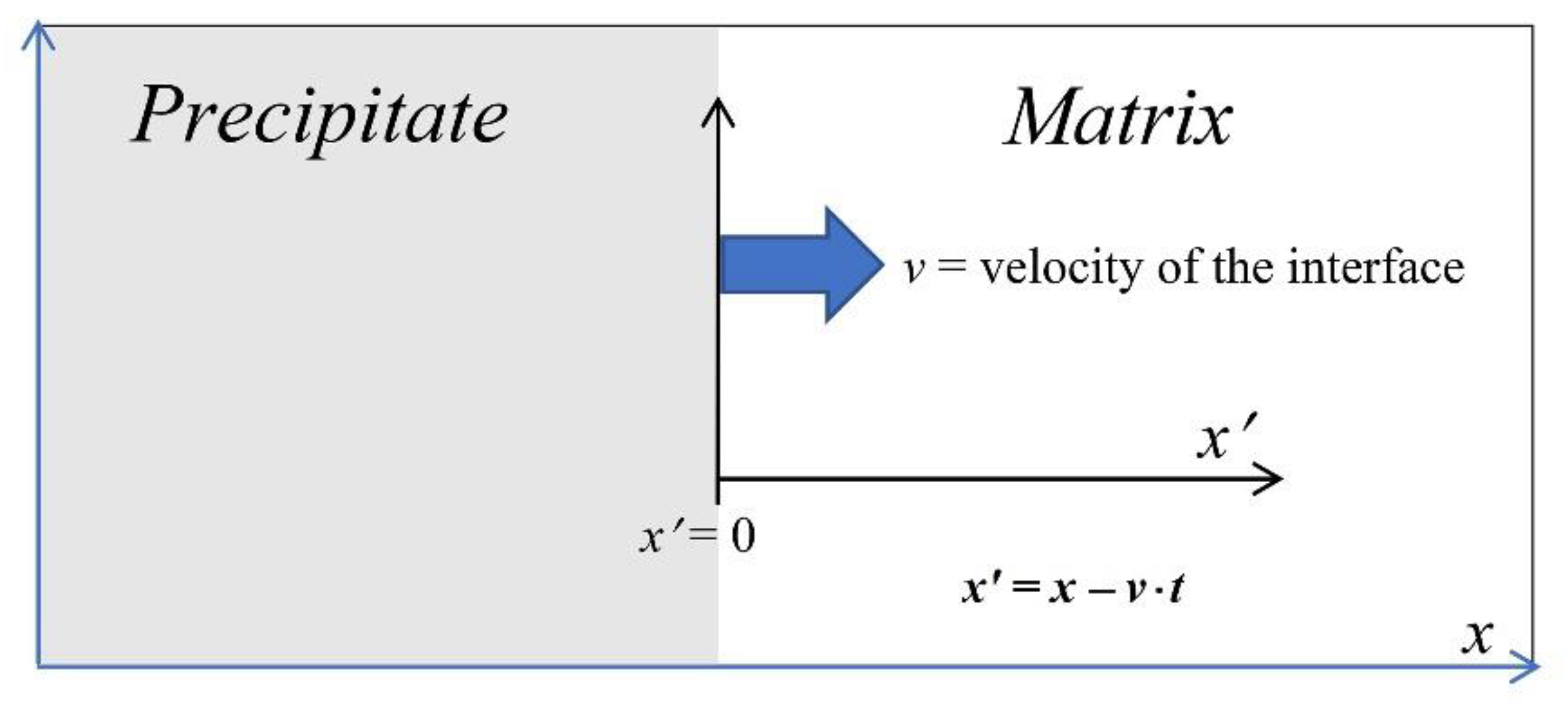
Figure 1. Relationship between the stationary (x) and the moving (x′) reference frames for a precipitate growing at the expense of the matrix.
Metals 09 00889 g001
Figure 2. The concentration profile along the main axis of a dissolving ellipsoidal precipitate. The coordinate ρ is defined in the ellipsoidal system of coordinates.
Metals 09 00889 g002
Figure 3. Evolutions of (a) the radius and (b) the Cu molar fraction at the interface of a spherical θ-Al2Cu precipitate dissolving in an infinite matrix with different values of the interfacial mobility.
Metals 09 00889 g003
Figure 4. Schematic of the time discretization technique evaluating the interface velocity in the finite system.
Metals 09 00889 g004
Figure 5. Coefficient of diffusion as a function of the Cu molar fraction in an Aluminum rich matrix at 600 K and 730 K, estimated with Thermo-Calc and the databases TCAL5 [13] and MOBAL1 [14].
Metals 09 00889 g005
Figure 6. Size evolution of a spherical θ-Al2Cu growing in a finite Al-1.0 at%Cu matrix with four different values of the interfacial mobility. The number density of the precipitates is assumed to be 1.0 × 10¹⁸ m−3.
Metals 09 00889 g006
Figure 7. Evolution of c ¯ and c * for a spherical θ-Al2Cu precipitate growing in a finite Al-1.0 at%Cu matrix with different values for the interfacial mobility.
Metals 09 00889 g007
Figure 8. Time evolution of the radius of a spherical θ-Al2Cu θ inside a finite Al-1.0 at %Cu matrix at 600 K with three different values for the number density.
Metals 09 00889 g008
Figure 9. Solute concentration profiles in front of the spherical θ-Al2Cu as calculated by DICTRA at different times for systems having different values for the number density.
Metals 09 00889 g009
Figure 10. Time evolution of the radius of a spherical θ-Al2Cu precipitate dissolving in a finite Al-1.0 at%Cu matrix at 730 K with three different values for the interfacial mobility. The number density of the precipitates is assumed to be 1.0 × 10¹⁸ m−3.
Metals 09 00889 g010
Figure 11. Time evolution of c ¯ and c * for a spherical θ-Al2Cu precipitate dissolving in a finite matrix with three different values for the interfacial mobility. The number density of the precipitates is assumed to be 1.0 × 10¹⁸ m−3.
Metals 09 00889 g011
Table 1. Parameters defining the growth of θ-Al2Cu precipitates in the Al–Cu system.
ParameterValue
Temperature (K)600
Nominal molar fraction of Cu, c 0 0.01
Radius of the precipitate at the start of the mixed-mode model, ac2 nm
Number density of precipitate, N β 1 × 10¹⁸ m−3
Radius of the precipitate at the start of simulation2 nm
Initial layer thickness of the matrix in the DICTRA model618.4 nm
Molar volume of the precipitate, Vm1 × 10−5 m3/mol
Table 2. Thermodynamic variables used in the models.
ParameterValue
The maximum molar fraction of Cu in the matrix at 600 K, c e q 0.00285
Molar fraction of Cu in the precipitate0.33
Molar fraction of Al in the precipitate0.67
Surface energy, γ0
Table 3. Parameters describing the dissolution of θ-Al2Cu precipitates in the Al–Cu system. All other parameters are the same as in Table 1 and Table 2.
ParameterValue
Temperature (K)730
The maximum molar fraction of Cu in the matrix c e q 0.011
Radius of the precipitate at the end of the mixed-mode model, ac2 nm
Radius of the precipitate at the start of simulation175 nm
Initial layer thickness of the matrix in the DICTRA model445.4 nm