Article

Influence of Heat Treatments on Heat Affected Zone Cracking of Gas Tungsten Arc Welded Additive Manufactured Alloy 718

1
Department of Engineering Science, University West, 461 32 Trollhättan, Sweden
2
Department of Mechanical Engineering, University of Manitoba, Winnipeg, MB R3T 5V6, Canada
*
Author to whom correspondence should be addressed.
Metals 2019, 9(8), 881; https://doi.org/10.3390/met9080881
Submission received: 28 June 2019 / Revised: 2 August 2019 / Accepted: 3 August 2019 / Published: 10 August 2019
(This article belongs to the Special Issue Welding Metallurgy and Weldability of Superalloys)

Abstract

:
The weldability of additive manufactured Alloy 718 was investigated in various heat-treated conditions. The microstructure of the base metal was examined in detail in order to understand the effect of different pre-weld heat treatments; i.e., solution, solution and aging, and hot isostatic pressing. After welding, the variation in total crack lengths, maximum crack length and the total number of cracks in the heat affected zone (HAZ) were used as criteria for the cracking susceptibility of each material condition where wrought Alloy 718 was used as the reference material. Selective laser melting (SLM) manufactured Alloy 718 was susceptible to HAZ cracking in all material conditions. Total crack lengths in HAZ were highest in the SLM as-built condition and lowest in the SLM hot isostatic pressed condition. The cracks that were found in the HAZ of the welded materials consisted of liquation cracks, with eutectic product surrounding the cracks, as well as cracks from which liquation products were absent.

1. Introduction

Selective laser melting (SLM) is an additive manufacturing (AM) process for fabricating near net shape parts using fine metal powders. SLM systems utilize a laser to selectively melt a bed of metallic powder layer by layer to build the physical part. The SLM process shows potential to produce functional metallic parts with complex geometries that cannot easily be produced by conventional processes [1]. However, the production of parts with SLM is limited by the size of the production chamber. Hence, production of large components, such as turbine structures for aero engines, will require joining different small SLM-manufactured parts together by welding. Furthermore, the SLM process can also be used to produce replacements of damaged or worn-out parts, which can subsequently be welded to the components.
Alloy 718 is an iron–nickel base precipitation hardening superalloy that is used in hot structural parts of gas turbine engines due to its combination of high strength and corrosion resistance at elevated temperature. The alloy exhibits resistance to strain-age cracking (SAC) during post-weld heat treatment (PWHT) and can therefore be used in applications that require welding. The microstructure of the alloy consists of a γ-matrix dispersed with precipitates including γ’’ (Ni3Nb), γ’ [Ni3(Al, Ti)], δ-phase (Ni3Nb), Laves phase [(Ni, Fe, Cr)2(Nb, Mo, Ti)], and various metal carbides and nitrides, such as NbC, TiC, and TiN. The main strengthening phase in the alloy is γ’’ that is formed due to the addition of about 5 wt. % niobium (Nb) [2]. As has been long-known, the presence of NbC and Laves phase in Alloy 718 can contribute to hot cracking in the heat-affected zone (HAZ) during welding [3,4,5,6]. The overall microstructure of a material, including existing phases, their morphology, and distribution is directly related to the manufacturing process and subsequent post-processing conditions. Typically, Alloy 718 is utilized in either wrought or cast condition followed by post-processing to generate the optimized microstructure for the specific use or application. Previous studies regarding the weldability of Alloy 718 in cast and wrought forms, have shown that the extent of HAZ liquation cracking can be influenced by the pre-weld heat treatment. Researchers have concluded that solution heat treatment can reduce cracking susceptibility [7] in Alloy 718 and age hardening can increase it [8]. That is why the usual procedure within industry is to weld the alloy in the solution-annealed condition and then subject it to solution and aging heat treatment after welding. The solution heat treatment relieves the residual stresses after the welding process and the aging heat treatment develops the strengthening phases. However, in some cases, such as repair welding, the alloy needs to be welded in aged condition.
The microstructure of SLM-manufactured Alloy 718 in the as-built condition is more similar to cast material (although on a much finer scale) or the fusion zone (FZ) of welded Alloy 718 than to wrought material. The grains have a dendritic structure and are mostly oriented in the building direction of the component. The microstructure contains NbC carbides and low melting Laves phase in the interdendritic regions and along the grain boundaries.
In an early study from 1966 regarding HAZ cracking in the nickel-based superalloys, Owczarski et al. [9] reported that constitutional liquation was initiated in the vicinity of MC-type carbides (where M is principally Nb but can also contain Ti). They suggested that the abrupt decomposition of these particles occurred during rapid heating, leading to constitutional liquation, grain boundary wetting, and subsequent cracking. They also found that, during rapid heating, a partially melted zone (PMZ) was formed in the welded alloy by constitutional liquation reactions involving the decomposition of MC-type carbide particles. The PMZ is the area immediately outside the weld metal FZ [9,10], and the main characteristic of this area is the presence of a liquid fraction that forms when the temperature exceeds the solidus temperature during heating. The formation of stresses in the PMZ, during subsequent weld cooling, can cause crack formation. Baeslack and Nelson [3] studied the HAZ liquation cracking in cast Alloy 718 and concluded that melting of the Laves phase in the interdendritic regions promoted liquation cracking in the HAZ. The Laves phase forms during the terminal solidification of casting, and simply re-melts in the HAZ during welding. On the other hand, NbC decompose during rapid heating and promote constitutional liquation cracking in both wrought and cast Alloy 718 [4,8]. Due to the high-volume fraction of Laves phase present in cast Alloy 718, liquation can be extensive, resulting in increased cracking sensitivity relative to the wrought counterparts.
The physical and chemical reactions in the HAZ of the welded samples are related to the thermal process that occurs during welding. Metallurgical reactions, phase transformations, and recrystallization of grains are closely related to this thermal process. The thermal cycle imposed on the HAZ greatly influences the degree of constitutional liquation, precipitate dissolution, and grain boundary segregation that can occur. All these factors influence the amount of liquid that forms along the PMZ grain boundaries. By measuring the temperature distribution and cooling rate in the HAZ using implanted thermocouples, it is possible to determine the thermal crack susceptible region surrounding the weld within which HAZ liquation cracking is possible.
In the present investigation, the susceptibility towards hot cracking during gas tungsten arc welding (GTAW) of SLM-manufactured Alloy 718 was investigated in various heat-treated conditions. Wrought Alloy 718 was used as the reference material. The temperature distribution in the HAZ was also measured in order to obtain increased insight into the type of cracking occurring in the material. Additionally, possible reasons for HAZ cracking in welded SLM manufactured material are discussed.

2. Materials and Methods

2.1. Material and Heat Treatments

The SLM-manufactured plates were built with a Realizer SLM125 system with a build chamber of 125 × 125 × 180 mm3 and a 200 W SPI Ytterbium fiber laser (Realizer GmbH, Borchen, Germany) with laser beam spot diameter of 20 µm. Powder with a particle size distribution from 15 to 45 µm, supplied by LPW Technology UK, was utilized for the processing of the samples. The thickness of the deposited powder layer was set to 60 µm in this study. The fabrication was conducted in a chamber that was filled with argon gas to maintain the oxygen level below <1000 ppm.
Test plates manufactured by the SLM process were 3.4 mm thick with dimensions of 50 mm in width and 100 mm in length. The plates had a rough surface and were therefore machined to 3.3 mm thickness before welding. Reference plates made from wrought Alloy 718 sheet material had a thickness of 3.2 mm with dimensions of 60 mm in width and 150 mm in length and were tested in the mill-annealed condition (mill annealing is a heat treatment given to all mill products to increase material ductility, reduce hardness, and make them workable). The chemical composition, in weight % (wt. %), for the gas-atomized (GA) powder used in the SLM of Alloy 718 is presented in Table 1, together with the chemical composition for wrought Alloy 718. The SLM-manufactured plates were tested in four different conditions: as-built, solution heat-treated (SHT), solution heat-treated and aged (SHT + AGE), and hot isostatic pressed (HIP). The heat treatments performed on the specimens are specified in Table 2. The mill-annealed condition refers to the wrought alloy.

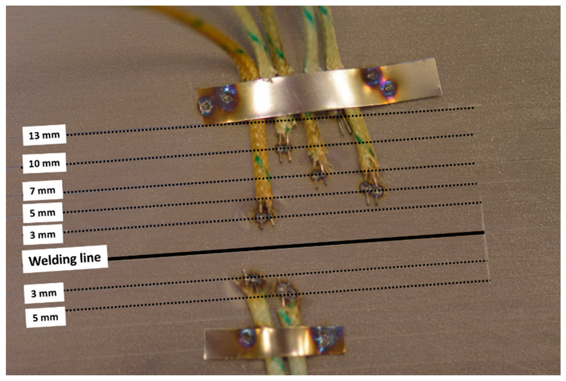
2.2. Temperature Distribution Tests

In the present study, the temperature measurement was implemented using K-type thermocouples with 0.2 mm wire diameter. Type-K thermocouples have a measuring range from −200 °C to 1250 °C [11]. They have an accuracy of ±0.75% which translates to around ±9.5 °C at 1250 °C. However, the melting temperature of the thermocouple is 1300 °C which is fairly close to the melting temperature of Alloy 718 which is ~1335 °C [12].
The weld piece had a thickness of 3.2 mm with dimensions of 60 mm in width and 150 mm in length. Thermocouples were positioned and affixed by electrical spot welding. Figure 1 shows the thermocouple locations on the test piece. The GTAW method was used for welding one bead-on-plate pass. Temperatures were measured at different distances from both sides of the weld line. To record the measured temperatures, the collected signals were transferred to a data logger and a computer. LabVIEW 2015 32 bit (NXG, National Instruments Sverige AB, Kista, Sweden) was used to display the thermal curves.

2.3. Welding Conditions, Sample Preparation, and Microscopic Examination

Bead on plate welding was carried out on the materials using an automatic GTAW process. Argon was used as a shielding gas, with a flow rate of 15 L/min. The welding parameters used were welding speed of 1 mm/s, welding current of 70 A, and arc voltage of 10 V. The welding parameters are based on a DOE (Design of Experiments) study which produced the lowest average total crack length and lowest standard deviation among different settings [13].
Five cross sections from each condition of the welded plates were excised for the measurements of total crack length (TCL), maximum crack length (MCL), total number of cracks, and in-depth microscopic investigations. Samples from weld cross sections were mounted, ground, and polished. TCL were first measured by taking images of all the cracks in the cross-sections with a Hitachi TM3000 tabletop scanning electron microscope (SEM) (Hitachi, Ltd., Tokyo, Japan) and then by measuring the cracks with a Lumenera Infinity Analyze 6.5 software (Version 6.5, Lumenera Corporation, Ottawa, ON, Canada). For further microscopic examination of cracks, the samples were electrolytically etched with oxalic acid. Additional SEM examination of the material and HAZ microstructure was performed on a Zeiss SEM EVO 50 (Carl Zeiss AB, Oberkochen, Germany) and a FEI Nova NanoSEM 450 (FEI Company, Hillsboro, OR, USA), equipped with a high-resolution field emission gun. To be able to see the precipitation hardening phases in the base metal, particularly in the SHT + AGE condition, the samples were electrolytically etched with phosphoric acid. Semi-quantitative SEM/EDS analyses were also performed to obtain approximations of elemental composition and concentrations.
Transmission electron microscopy (TEM) was performed on a FEI Talos F200X TEM (FEI Company, Hillsboro, OR, USA) equipped with a Super-X EDS system. Thin foils of base metal for TEM study were ground, polished to about 100 µm, and punched out in 3 mm coupons before subjecting them to dimpling and electro-polishing. The electro-polishing was performed using a Struers TenuPol-2 Twin-jet polisher (Struers Inc., Cleveland, OH, USA) in a solution of 10% perchloric acid and 90% methyl alcohol, at a temperature of around −40 °C, a voltage of 1.5 V, and 1.0 A DC current.
Microhardness, HV1 (9.807 N) 15 s, was measured for each of the five material conditions using a Shimadzu HMV-2 microhardness tester (Shimadzu Scientific Instruments, Kyoto, Japan). Ten readings were recorded for each material condition and the average was determined as the hardness value.

3. Results

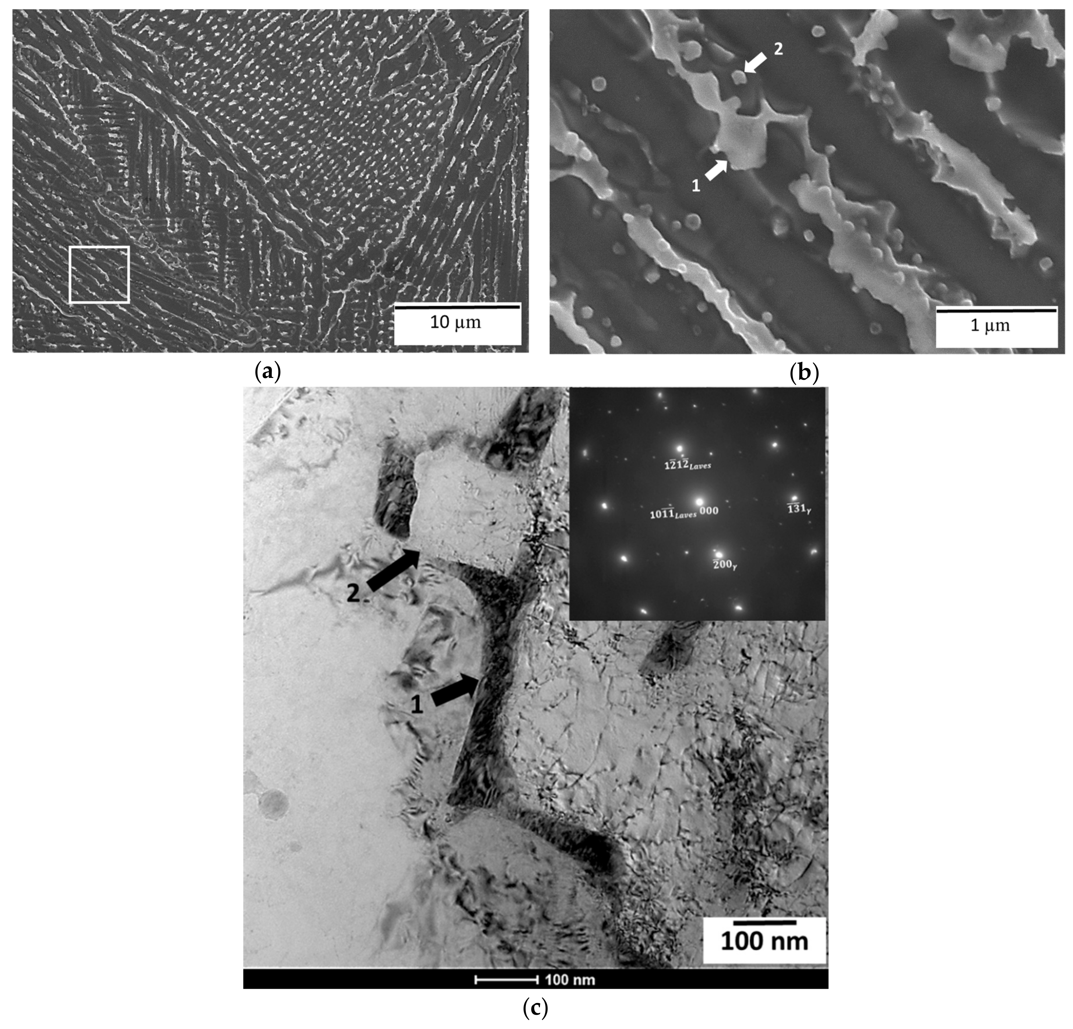
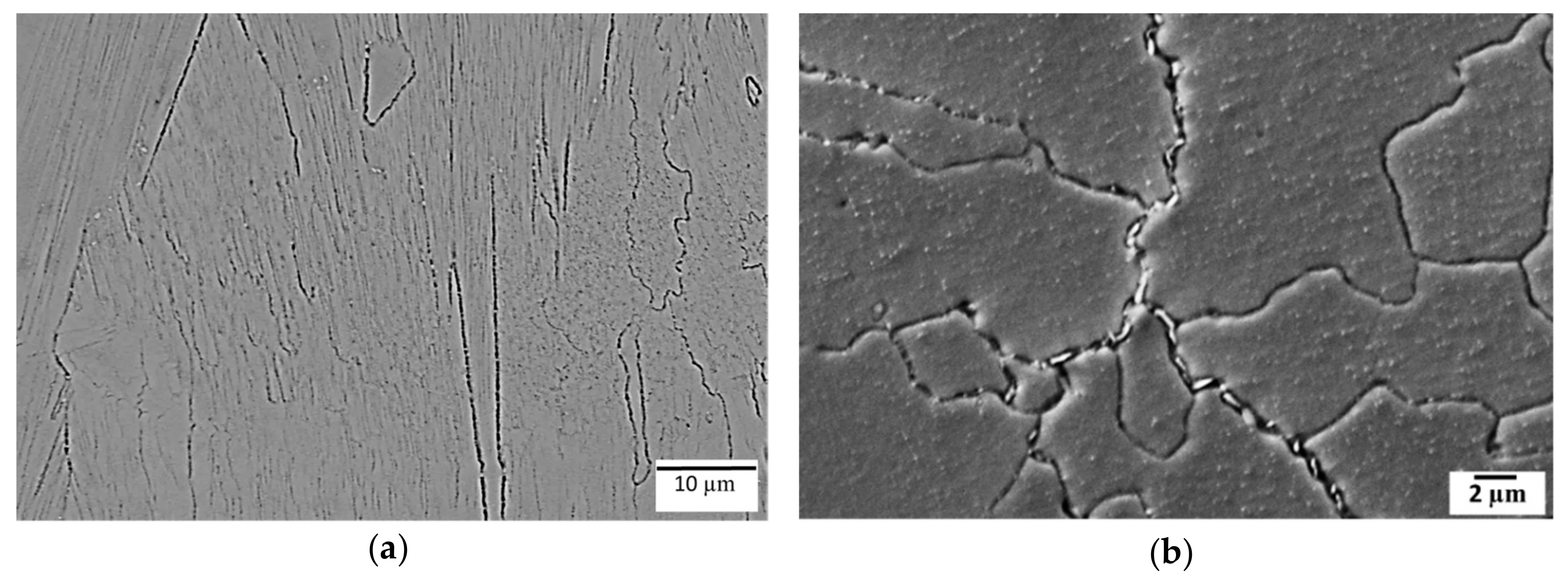
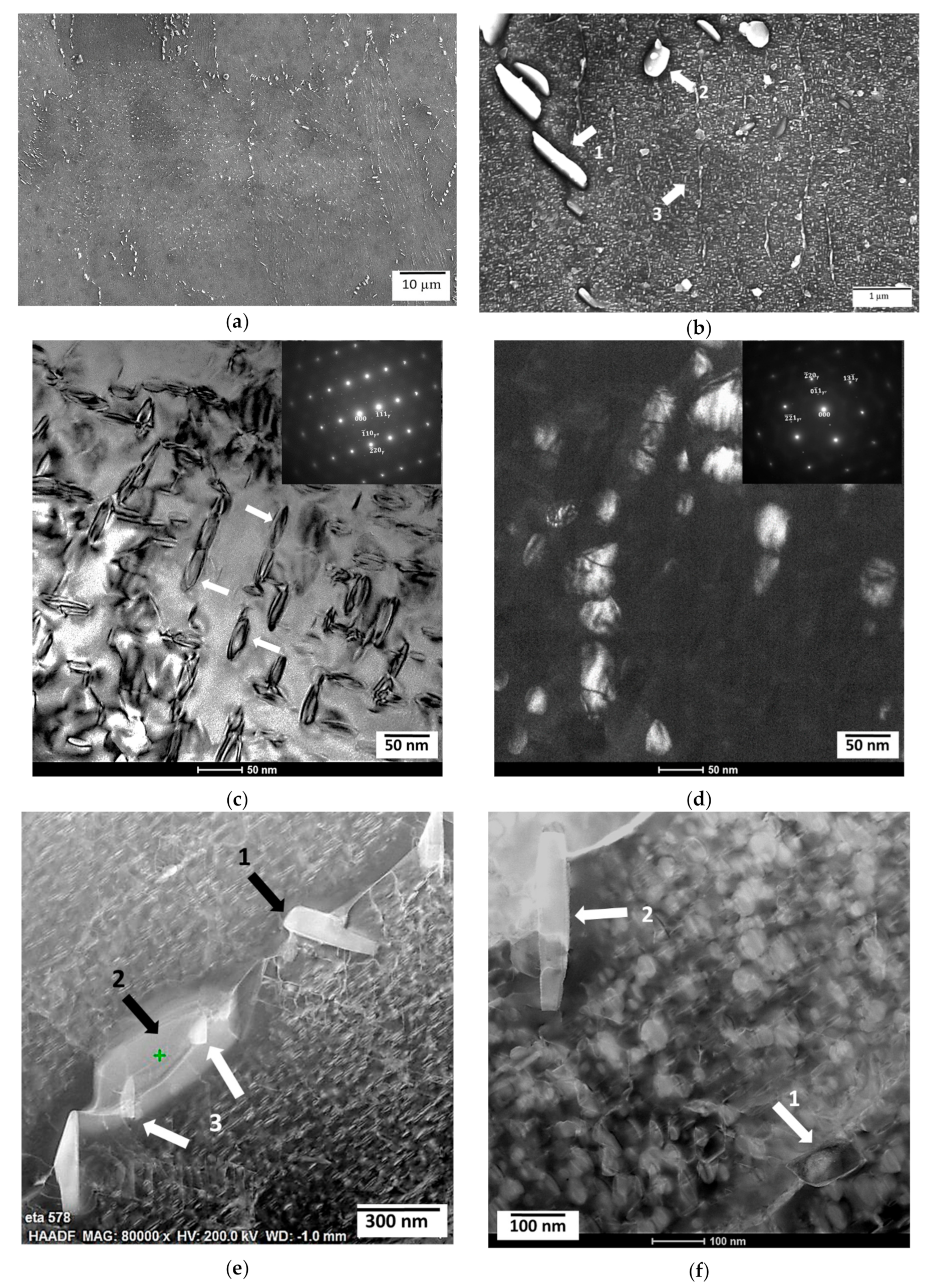
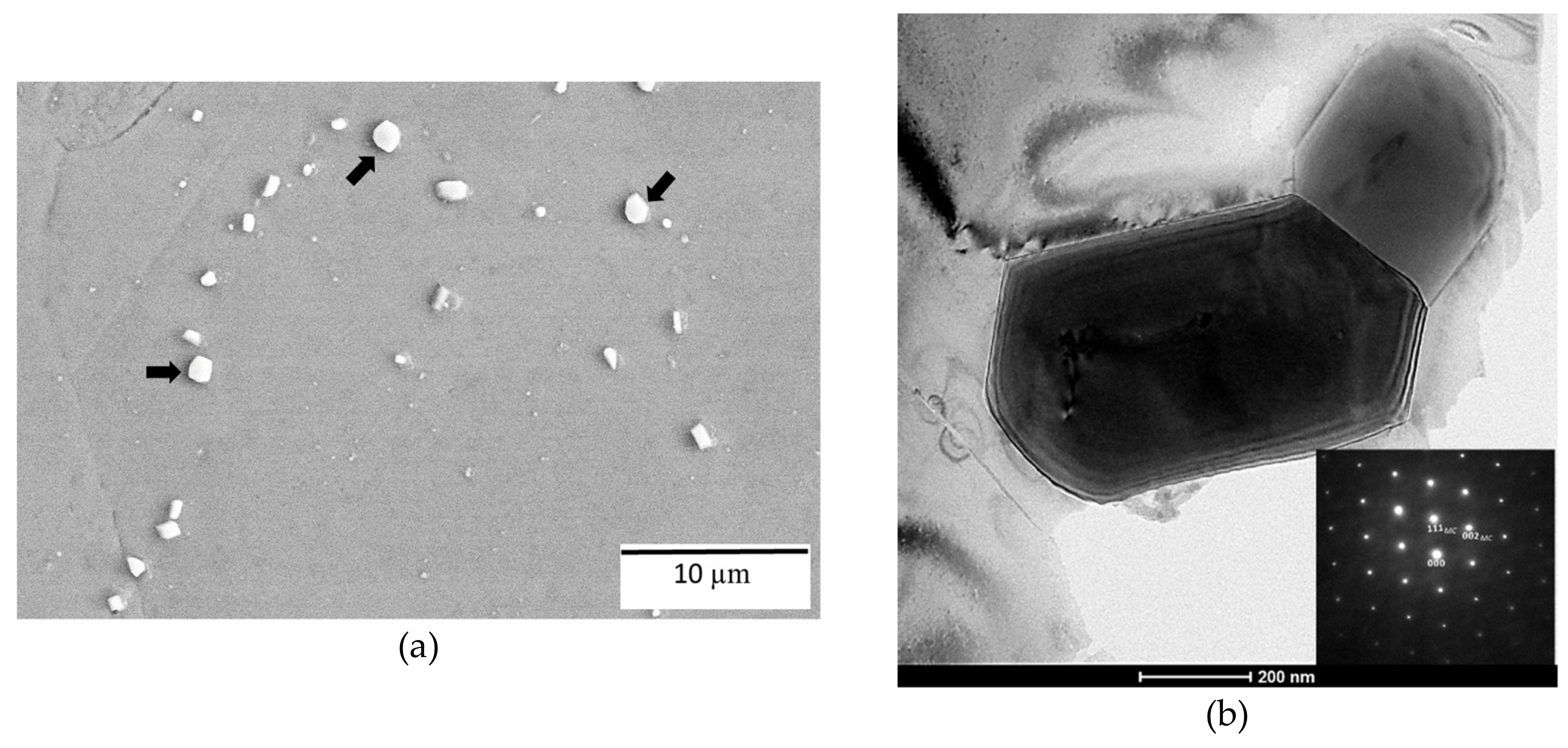
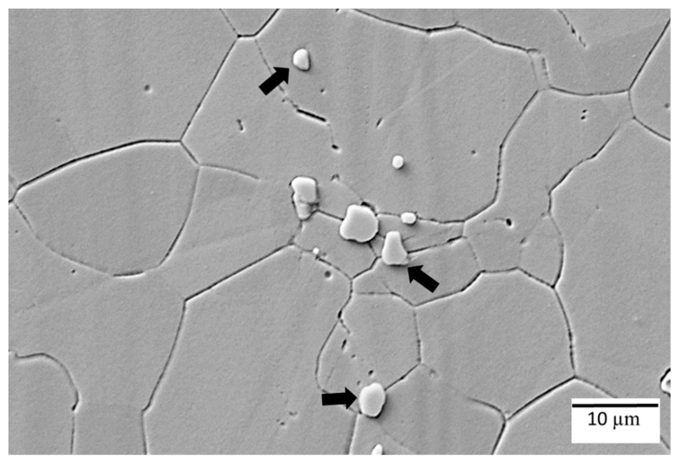
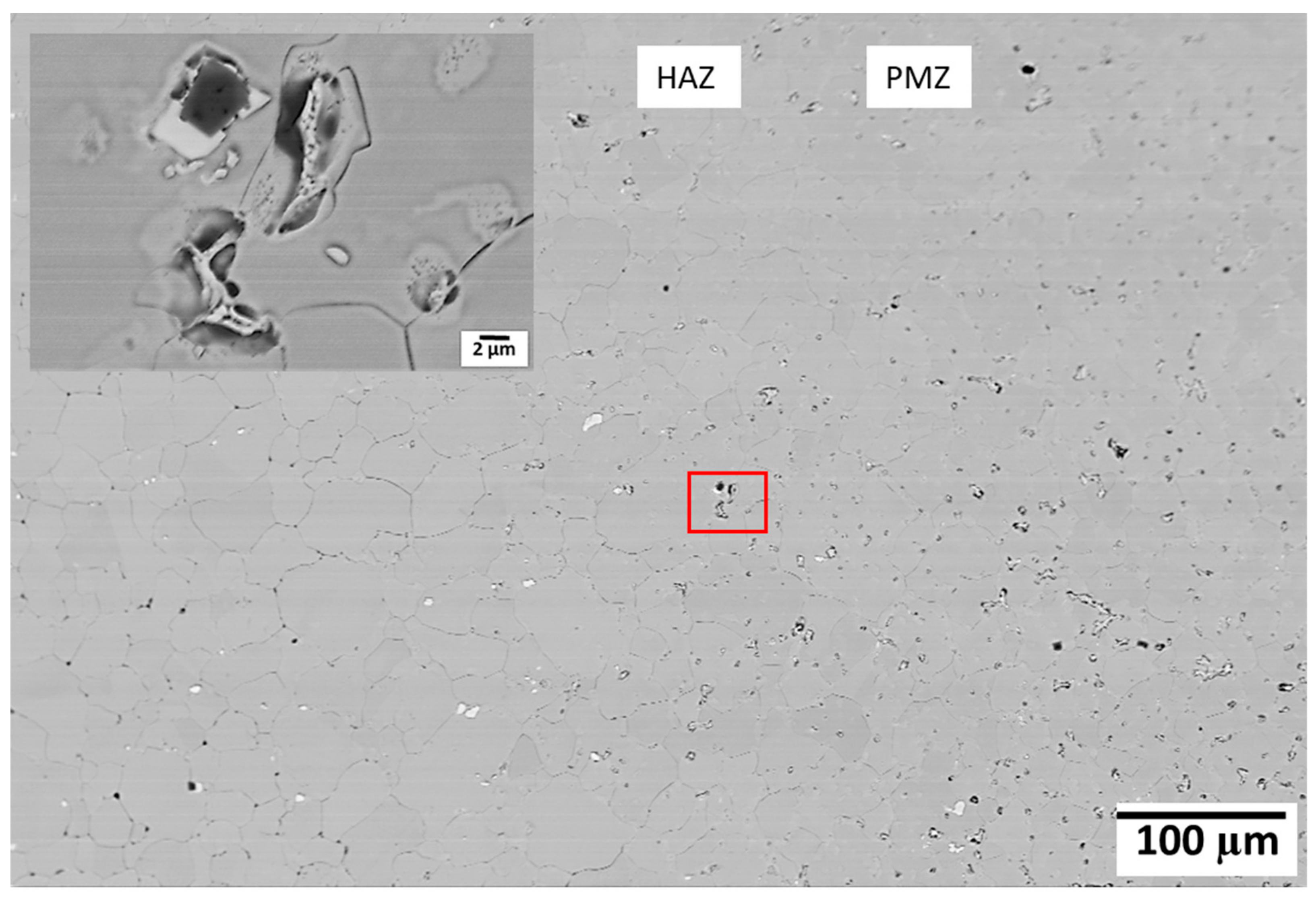
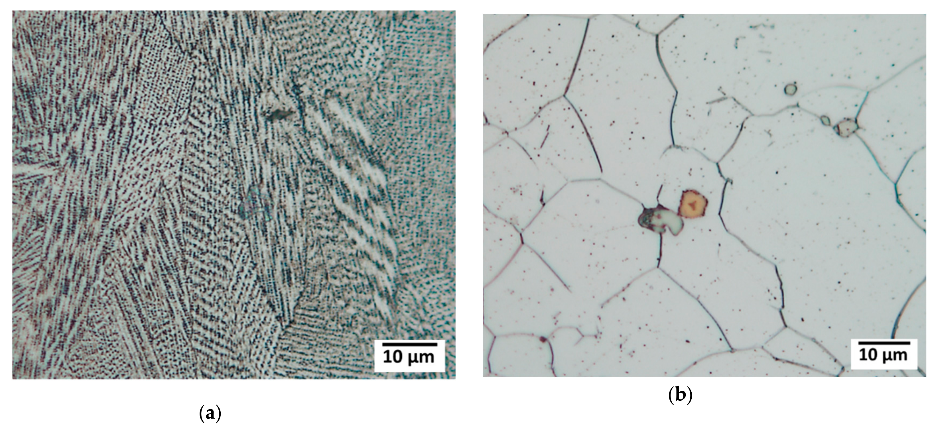
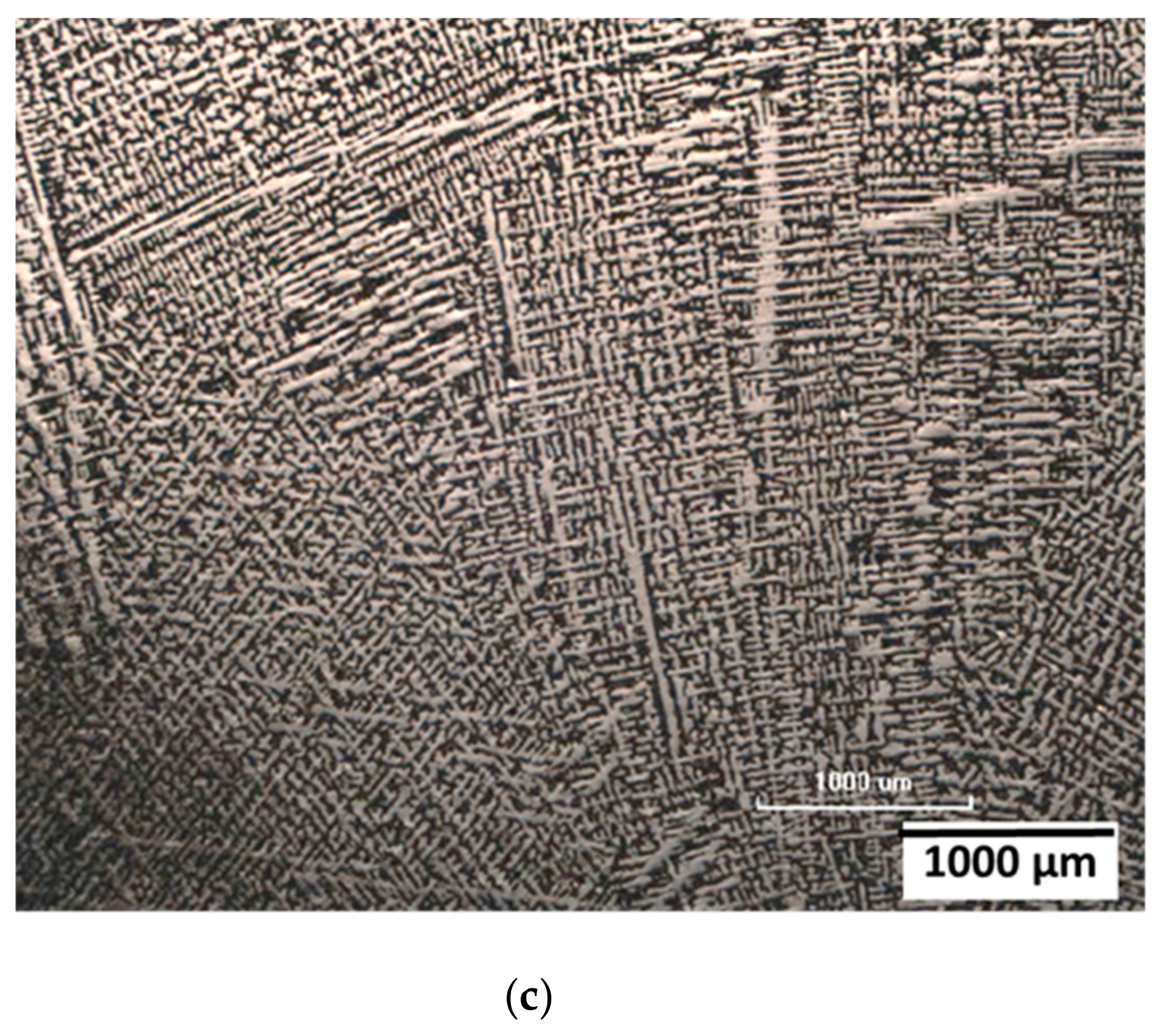
3.1. Base Metal Microstructure

The microstructure of all five conditions of the base metal are presented in Figure 2, Figure 3, Figure 4, Figure 5 and Figure 6. The secondary phases observed in the microstructure were examined by SEM and TEM. The chemical composition of the phases present was determined by EDS analyses and these are summarized in Table 3. The chemical compositions included in the table are the average of five measurements. Phases were tentatively identified by their unique characteristic morphologies and by their chemical compositions.
In the as-built condition in Figure 2a, a dendritic solidification structure with particles along the interdendritic region can be seen. As shown in the SEM image in Figure 2b, the as-built condition disclosed significant segregation, with the lighter regions being the interdendritic area. The TEM/EDS analyses (Table 3) suggested that the lamellar and the irregular-shaped particles were associated with Laves phase and MC-type carbides, respectively. More in-depth analyses by TEM were performed to confirm the nature of the particles. The bright field (BF) image in Figure 2c shows Laves phase and NbC carbide along the interdendritic regions. The inset shows the diffraction pattern (DP) of Laves phase in the γ-matrix.
After solution heat treatment (SHT) at 954 °C for 1 h, the dendritic structures within the grains were still present (Figure 3a), along with MC-type carbides, remnants of Laves phase, and plate-like δ-phase (Ni3Nb) (Figure 3b) present in the microstructure.
After the SHT followed by a two-step aging treatment (5 h at 760 °C and 1 h at 649 °C), δ-phase and carbides still remained in the microstructure, along with the precipitated strengthening phases of γ’ and γ’’ in the matrix (Figure 4a,b). The TEM BF image and DP in Figure 4c show the presence of strengthening precipitates γ’’. The dark field image in Figure 4d is the same area as in Figure 4c, and DP confirms the presence of γ’ precipitates in the γ-matrix. In Figure 4e, δ-phase forming from the Laves phase can be seen. In Figure 4f, δ-phase and carbide residing on the grain boundaries can be seen. TEM/EDS analyses also confirmed the presence of these phases.
After HIP treatment of the as-built specimens, the dendritic structure from the SLM processing disappeared and the grains grew into a coarser and equiaxed grain structure (Figure 5). The Laves phase was totally dissolved but residual NbC carbides were observable in the microstructure. The TEM BF image and DP confirm the presence of carbides in the matrix.
The microstructure of wrought Alloy 718 consisted of equiaxed grains, with NbC carbides mostly residing on the grain boundaries (Figure 6).
Table 3 presents the values from the EDS analyses determining the chemical composition of the different phases from the as-built, SHT, SHT + AGE, and HIP conditions.

3.2. Hardness Measurements

Table 4 shows the measured hardness values in all conditions of base metal. The SLM as-built and SHT conditions had relatively higher hardness even though both are assumingly free from strengthening phases of γ’’ and γ’. The SHT + AGE condition had the highest hardness of all due to the precipitation of the hardening phases, i.e., γ’’ and γ’.

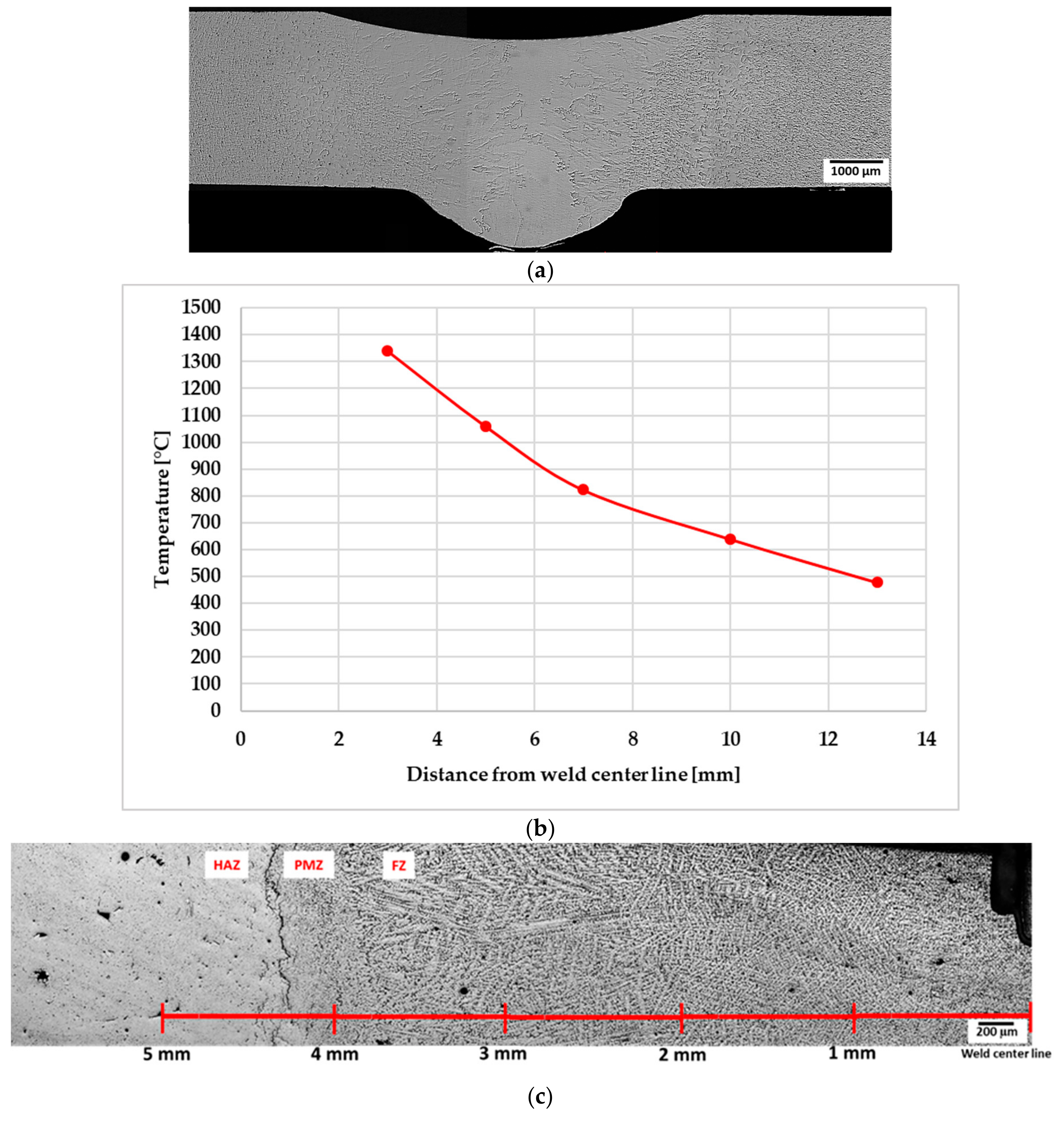
3.3. Temperature Measurements

Figure 7a shows a weld cross section of a welded sample, and Figure 7b presents the peak temperatures recorded from the respective thermocouples in the material during the welding process as a function of distance from weld centre line. Figure 7c shows the FZ, PMZ, and HAZ of the welded sample, and the distance of these zones from the weld centre line.

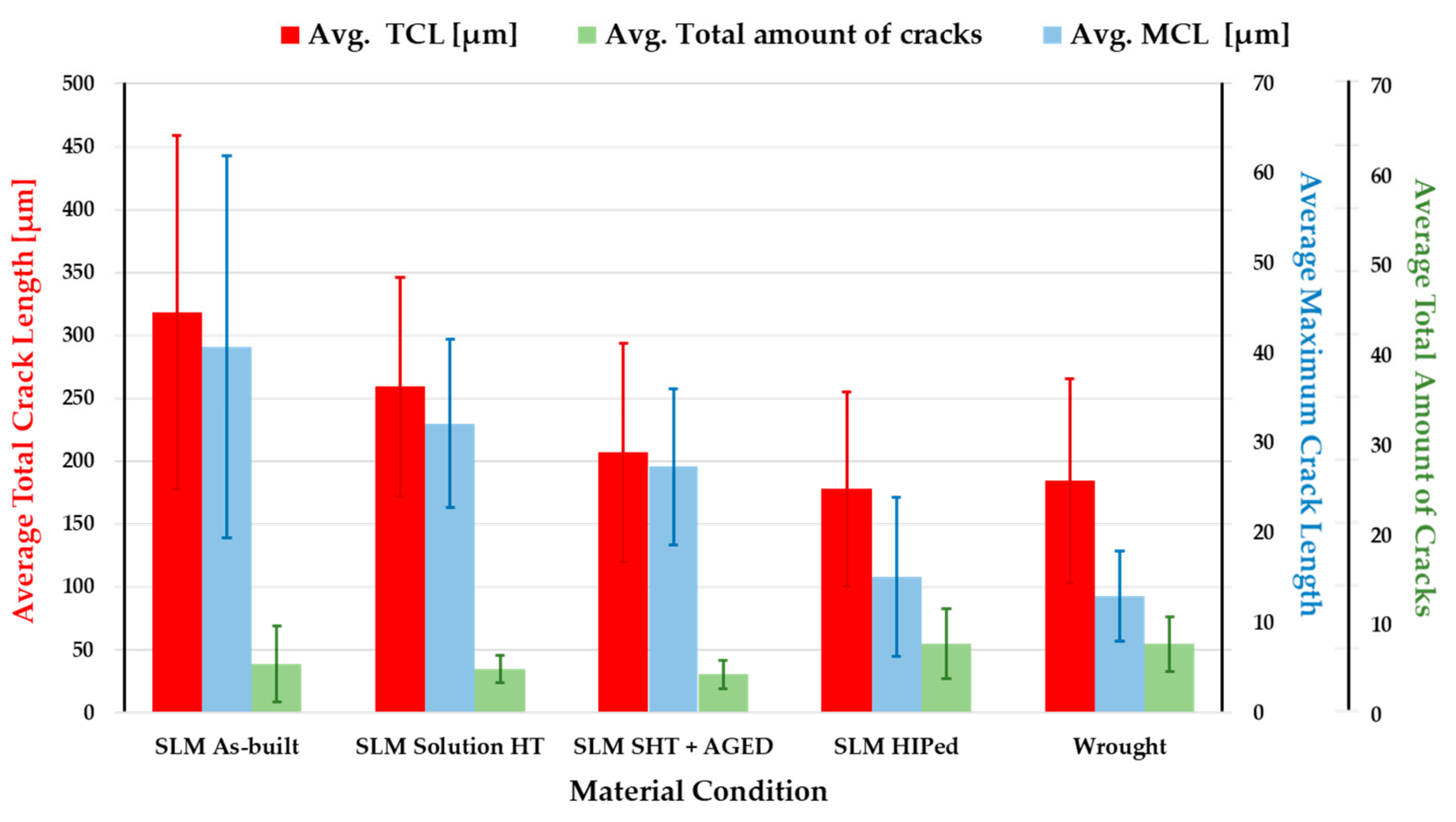
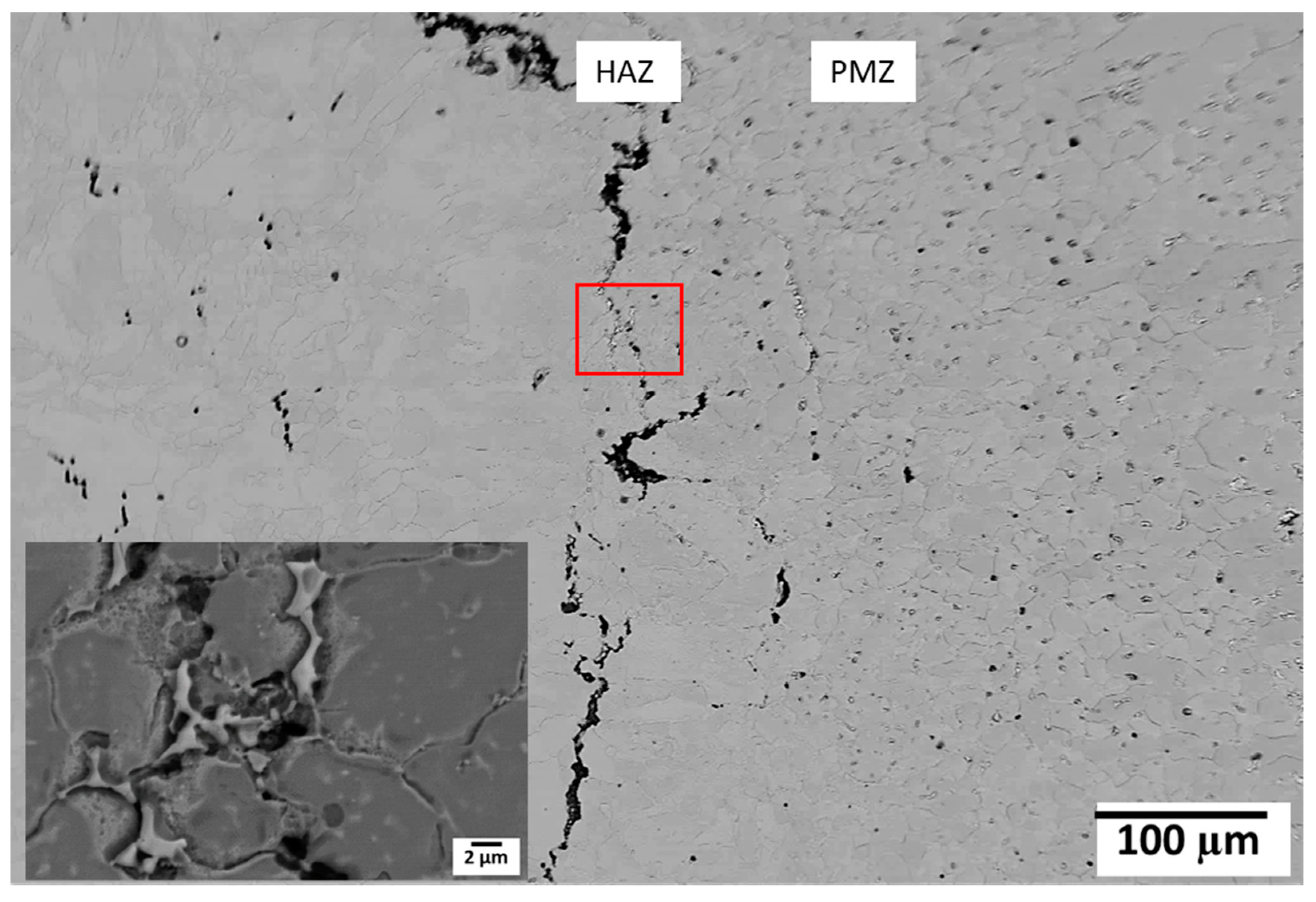
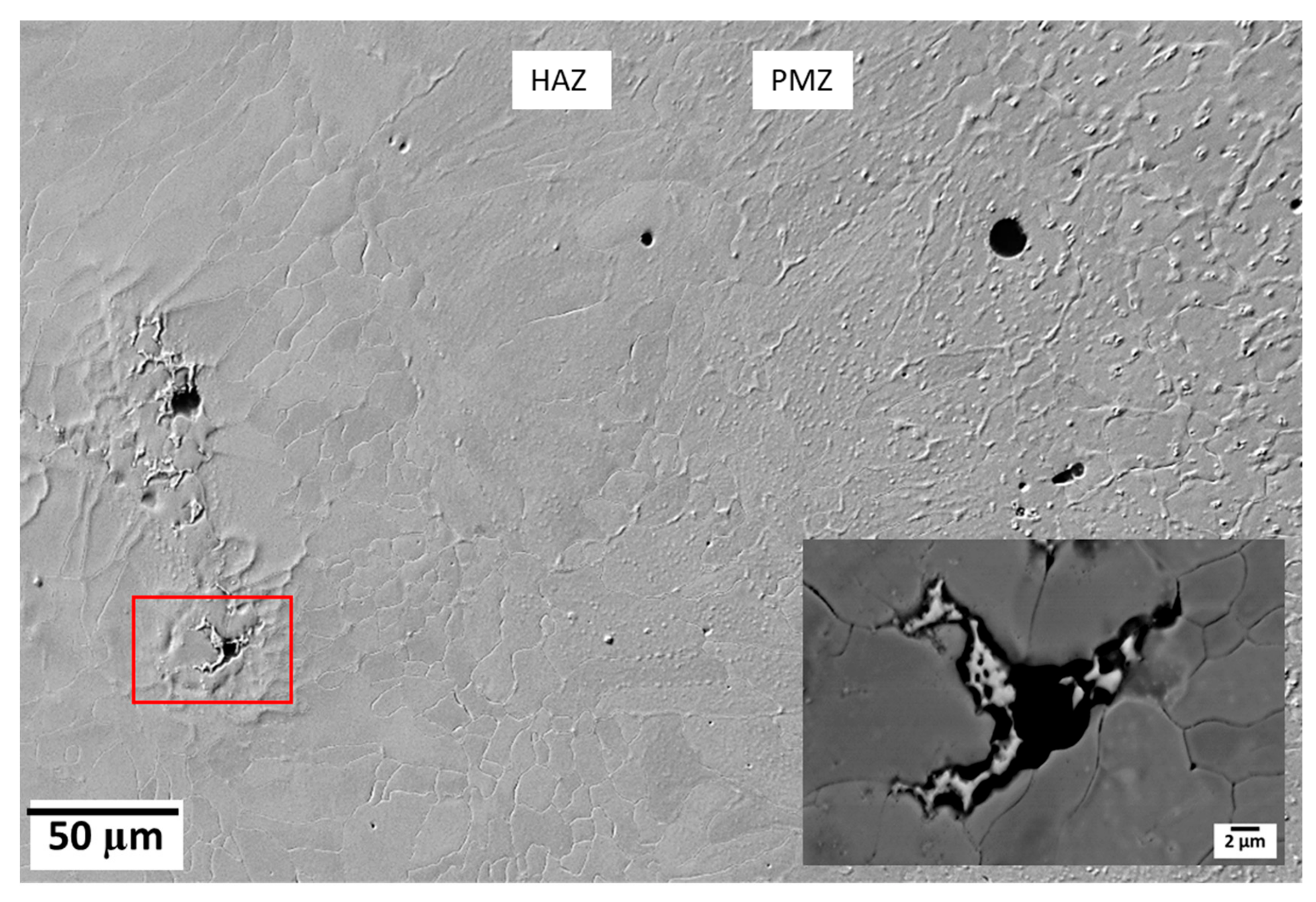
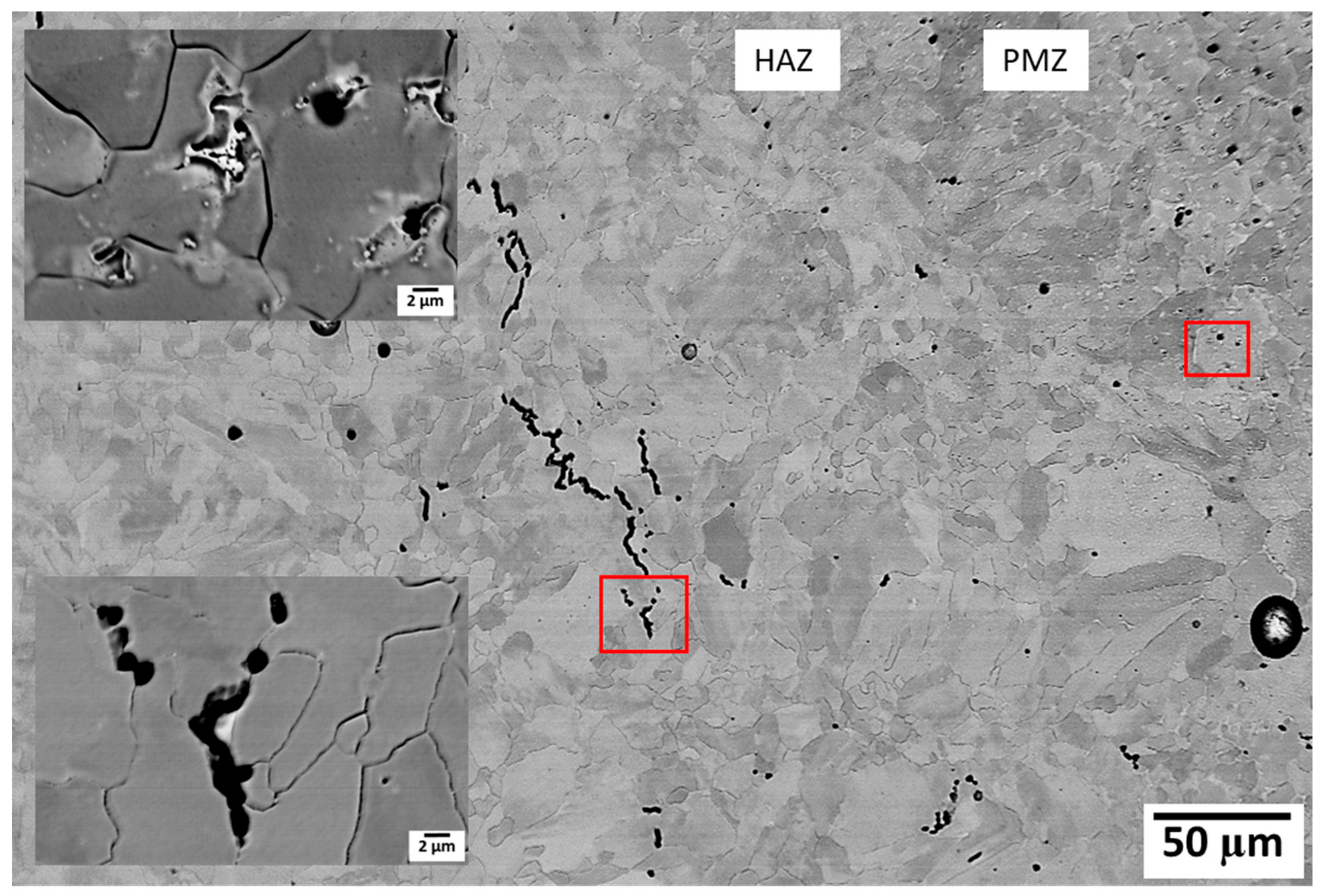
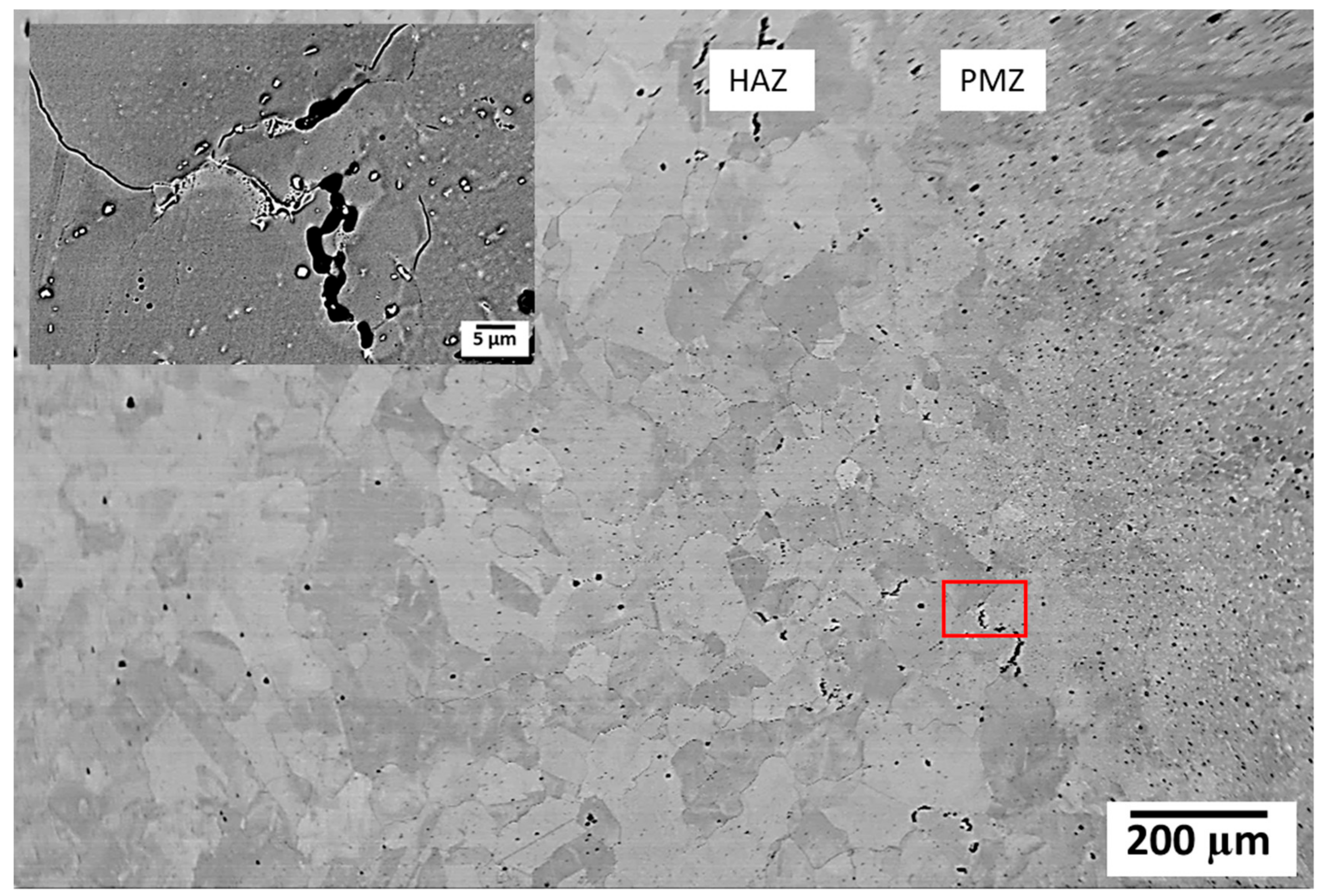
3.4. HAZ Cracking Susceptibility

The concept of weldability in this study was considered as the ability to resist HAZ cracking during GTAW. The welded specimens were cut into sections perpendicular to the welding direction (Figure 7a). The cracking tendency after different heat treatments was evaluated using TCL, MCL, and total number of cracks in the welded samples. TCL is the summation of all crack lengths and MCL is the length of the longest crack observed in the HAZ of welded samples. Averages of the TCL, MCL, and total number of cracks from five samples of each material condition were used as the criteria for cracking susceptibility in the HAZ (Figure 8). SLM-manufactured Alloy 718, in the as-built condition, was most susceptible to HAZ cracking. Cracking susceptibility, however, decreased after SHT, and decreased further in the SHT + AGE samples. In samples subjected to HIP directly after the SLM process, the cracking susceptibility was similar to that of wrought Alloy 718. The average MCL was highest in the SLM as-built condition and decreased with SHT. A further decrease was observed in the SHT + AGE condition. In the SLM–HIP condition, the MCL was similar to that of the MCL in the wrought condition. The total number of cracks was highest in the HIP and wrought conditions because there was a higher number of smaller cracks in these two conditions. Figure 9, Figure 10, Figure 11, Figure 12 and Figure 13 show evidence of grain boundary liquation in the HAZ of all the material conditions used in the present study. Figure 11 also shows an example of a “clean” crack without any apparent liquation product.

4. Discussion

In the present study, the weldability of the SLM-manufactured Alloy 718 was investigated in different heat-treated conditions. The definition of weldability was here considered as the susceptibility towards hot cracking in the HAZ. The SLM-manufactured samples were mainly compared to wrought Alloy 718 of approximately the same thickness as the SLM samples. However, some comparisons to a cast Alloy 718 sample were also made. By comparing the microstructure of the different manufacturing techniques, it is obvious that SLM-manufactured Alloy 718 in the as-built condition (Figure 14a) is very different from the wrought form (Figure 14b), but somewhat more similar to the cast form (Figure 14c), however, on a much finer scale. The different scale bars in Figure 14 should be noted. The fine scale of the SLM microstructure is due to the rapid solidification of the molten pool during the SLM process (compare Figure 14a,c).
Regarding weldability, all five material conditions examined in the present study appeared to experience the same process of HAZ liquation cracking. Presumably, the cause of the liquation could be different in different conditions. Microstructural examination suggested that in the SLM as-built, SHT, and SHT + AGE condition, incipient melting of Laves phase could be the cause of HAZ liquation cracking. This can be rationalized according to the literature regarding the HAZ liquation cracking in cast Alloy 718 that also contains Laves phase. On the other hand, by direct HIP of the SLM-manufactured Alloy 718 at 1160 °C for 4 h, the Laves phase was totally dissolved and carbides were apparently present in the microstructure. There were fewer cracks in the HAZ of the material and the average TCL was almost the same as in the wrought condition.
The argument proposed in the previous paragraph is reasonable due the fact that, in as-built condition, an extensive amount of Laves phase was present and the TCL was highest. The TCL decreased when the amount of Laves phase decreased in the SHT condition and a further decrease could be seen in the SHT + AGE condition where the amount of Laves was even lower than in the SHT condition. Direct HIP of the SLM-manufactured Alloy 718 dissolved all the Laves phase and carbides seemed to remain in the matrix. The average total number of cracks presented in Figure 8 also indicated the transition from fewer but longer cracks in the as-built condition, to shorter but more cracks in the HIP condition. This observation also supports the notion that less availability of low melting constituents in the matrix favors less cracking in the HAZ.
The grain size is another factor to be considered while discussing the weldability of the materials. It has generally been recognized that fine-grained materials are more resistant to HAZ liquation cracking than are coarse-grained versions of the same material [14]. Grains in the SLM-manufactured material were fine and elongated (Figure 14a). Grain size measurements performed in a previous study [15] showed that the SLM as-built specimen had an average grain length of 80 µm and width of 20 µm. The wrought Alloy 718 had an average grain size of around 25 µm. Grain size of the cast material is not clearly shown in Figure 14c, but another study [16] regarding hot cracking in cast Alloy 718, showed that the average grain size of as cast base metal was around 1700 µm. Thus, it could be expected that SLM-manufactured material in the as-built condition and wrought material would have similar cracking sensitivity, while as cast material would be much worse. However, this was not the case in the present study because the as-built condition had more cracks than the wrought.
In all SLM conditions in the present study, “clean” cracks, i.e., cracks without any eutectic formation, were also observed (for example, Figure 11). These cracks were in the HAZ where the temperature range during welding was between 1150 and 1200 °C (Figure 7a,b). The question is whether this has to do with any other cracking mechanism, for example segregation of elements such as B, P, C, or S in the grain boundaries [2,6,17]. According to the literature [18,19,20], B causes increased HAZ cracking sensitivity if present much above 0.003 wt. %. B in the powder feedstock used for the manufacturing of Alloy 718 with SLM process in the present study, was around 0.006 wt. % and was 0.003 wt. % in wrought Alloy 718. This could also be a reason for the higher cracking susceptibility of SLM material. This phenomenon requires further study for SLM- manufactured Alloy 718.
Another possible reason for relatively high cracking susceptibility in SLM material could be that the microcracks have already been created during the SLM process. Several nickel-base superalloys have been documented as being particularly susceptible to microcracking when processed by laser additive manufacturing process [21,22]. These microcracks can act as crack initiating sites during the cooling process after welding due to the local stresses in the material. HIP can be used to consolidate cracks; however, surface cracks and open porosity remain [23]. Furthermore, HIP can cause grain coarsening in the material (Figure 5a) that can also be an issue while welding. Each production process introduces some amount of residual stress [24]. Laser-based processes, such as laser welding and SLM, are known to introduce a huge amount of residual stress due to the large thermal gradients [25]. These process-induced residual stresses in SLM material can also influence the cracking behaviour when combined with complex welding stresses. Post-process stress-relieving heat treatments and solution heat treatment can decrease the amount of residual stress in the SLM material [26], which subsequently can reduce the cracking susceptibility of the material.

5. Conclusions

The present study investigated the influence of different heat treatments on the microstructure and weldability of selective laser melted Alloy 718. The gas tungsten arc welding method was used for welding of the samples. The following conclusions were drawn from the study:
  • SLM-manufactured Alloy 718 was susceptible to HAZ cracking in all material conditions, i.e., solution heat treated, solution and aging heat treated, and hot isostatic pressed.
  • Cracks seen in the HAZ of the welded material were of two types; those with eutectic products surrounding the cracks and “clean” cracks without any apparent liquation product.
  • Liquation cracks were due to the liquation of secondary constituents present in the SLM-manufactured material.
  • Total crack lengths in HAZ were highest in the SLM as-built condition and decreased in samples that were solution heat treated before welding. Total crack lengths decreased further in the solution and aged samples and were lowest in hot isostatic pressed samples.
  • As all heat treatment in the present study decreased the cracking susceptibility, it is recommended that the SLM material be welded in a heat-treated condition. However, the proper heat treatment must be designed to address fabricability challenges for the specific component at stake.

Author Contributions

Conceptualization, investigation, validation, and writing—original draft preparation, T.R.; Supervision, conceptualization, and editing, J.A. and L-E.S.; Supervision, O.A.O.; Experimental work, K.H. and G.A.

Funding

The authors gratefully acknowledge financial support from the Swedish National Space Board and VINNOVA (National Space Research Program and National Aerospace Research Program).

Acknowledgments

The authors acknowledge the support and input from GKN Aerospace Sweden AB. Special thanks to Abdul Khaliq Khan at the University of Manitoba, Canada for his help with TEM analyses.

Conflicts of Interest

The authors declare no conflict of interest.

References

  1. DebRoy, T.; Wei, H.L.; Zuback, J.S.; Mukherjee, T.; Elmer, J.W.; Milewski, J.O.; Beese, A.M.; Wilson-Heid, A.; De, A.; Zhang, W. Additive manufacturing of metallic components – Process, structure and properties. Prog. Mater. Sci. 2018, 92, 112–224. [Google Scholar] [CrossRef]
  2. Sims, C.T.; Stoloff, N.S.; Hagel, W.C. (Eds.) Superalloys II; Wiley-Inter Science: Hoboken, NJ, USA, 1987. [Google Scholar]
  3. Baeslack, W.A.; Nelson, D.E. Morphology of Weld Heat-Affected Zone Liquation in Cast Alloy 718. Metallography 1986, 19, 371–379. [Google Scholar] [CrossRef]
  4. Radhakrishnan, B.; Thompson, R.G. A phase diagram approach to study liquation cracking in Alloy 718. Metall. Trans. A 1991, 22, 887–902. [Google Scholar] [CrossRef]
  5. Ahn, Y.; Yoon, B.; Kim, H.; Lee, C. Effect of dilution on the behavior of solidification cracking in PTAW overlay deposit on Ni-base superalloys. Met. Mater. Int. 2002, 8, 469–477. [Google Scholar] [CrossRef]
  6. DuPont, J.N.; Lippold, J.C.; Kiser, S.D. Welding Metallurgy and Weldability of Nickel-Base Alloys; John Wiley and Sons: Hoboken, NJ, USA, 2009. [Google Scholar]
  7. Oshobe, O.E. Fiber laser welding of nickel-based superalloy Inconel 718. Master Thesis, University of Manitoba, Winnipeg, MB, Canada, June 2012. [Google Scholar]
  8. Thompson, R.G.; Radhakrishnan, B.; Mayo, D.E. Intergranular liquid formation, distribution, and cracking in the haz of alloy 718 welds. In Proceedings of the International Symposium on the Metallurgy and Applications of Superalloy 718, Pittsburgh, PA, USA, 12–14 June 1989. [Google Scholar]
  9. Owczarski, W.A.; Duvall, D.S.; Sullivan, C.P. Model for Heat-Affected Zone Cracking in Nickel-Base Superalloys. Weld J. 1966, 45, 145–155. [Google Scholar]
  10. Lippold, J.C. Welding Metallurgy and Weldability; John Wiley and Sons: Hoboken, NJ, USA, 2015. [Google Scholar]
  11. American National Standard Institute. ANSI Class 2 American Standard: ANSI/MC 96.1. Temperature Measurement Thermocouples; ANSI: New York, NY, USA, 1982. [Google Scholar]
  12. Donachie, M.J.; Donachie, S.J. Superalloys: A Technical Guide, 2nd ed.; ASM International: Materials Park, OH, USA, 2002. [Google Scholar]
  13. Andersson, J.; Jacobsson, J.; Lundin, C. A historical perspective on Varestraint testing and the importance of testing parameters. In Cracking Phenomena in Welds IV; Springer International Publishing: Basel, Switzerland, 2016; pp. 3–23. [Google Scholar]
  14. Thompson, R.G.; Cassimus, J.J.; Mayo, D.E.; Dobbs, J.R. The Relationship between grain size and microfissuring in Alloy 718. Weld. J. 1985, 64, 91–96. [Google Scholar]
  15. Raza, T.; Andersson, J.; Svensson, L.-E. Varestraint weldability testing of additive manufactured alloy 718. Sci. Technol. Weld. Join. 2018, 23, 606–611. [Google Scholar] [CrossRef] [Green Version]
  16. Singh, S.; Andersson, J. Hot cracking in cast alloy 718. Sci. Technol. Weld. Join. 2018, 23, 568–574. [Google Scholar] [CrossRef]
  17. Huang, X.; Richards, N.L.; Chaturvedi, M.C. Effect of Grain Size on the Weldability of Cast Alloy 718. Mater. Manuf. Process. 2004, 19, 285–311. [Google Scholar] [CrossRef]
  18. Lingenfelter, A. Welding of Inconel alloy 718: a historical overview. In Superalloy 718 Metallurgy and Applications; Loria, E.A., Ed.; The Minerals, Metals and Materials Society: Pittsburgh, PA, USA, 1989; pp. 673–683. [Google Scholar]
  19. Kelly, T.J. Welding Metallurgy of Investment Cast Nickel-based Superalloys. In Weldability of Materials; ASM International: Materials Park, OH, USA, 1990; pp. 151–157. [Google Scholar]
  20. Chen, W.; Chaturvedi, M.C.; Richards, N.L. Effect of boron segregation at grain boundaries on heat-affected zone cracking in wrought INCONEL 718. Metall. Mater. Trans. A 2001, 32, 931–939. [Google Scholar] [CrossRef]
  21. Segerstark, A. Laser Metal Deposition using Alloy 718 Powder: Influence of Process Parameters on Material Characteristics. Ph.D. Thesis, University West, Trollhättan, Sweden, December 2017. [Google Scholar]
  22. Harrison, N.J.; Todd, I.; Mumtaz, K. Reduction of micro-cracking in nickel superalloys processed by selective laser melting: a fundamental alloy design approach. Acta Mater. 2015, 94, 59–68. [Google Scholar] [CrossRef]
  23. Tillmanna, W.; Schaak, C.; Nellesen, J.; Schaper, M.; Aydinöz, M.E.; Hoyer, K.-P. Hot isostatic pressing of IN718 components manufactured by selective laser melting. Addit. Manuf. 2017, 13, 93–102. [Google Scholar] [CrossRef]
  24. Withers, P.J.; Bhadeshia, H.K.D.H. Residual stress. Part 2 – Nature and origins. Mater. Sci. Technol. 2001, 17, 366–375. [Google Scholar] [CrossRef]
  25. Mercelis, P.; Kruth, J.P. Residual stresses in selective laser sintering and selective laser melting. Rapid Prototyp. J. 2006, 12, 254–265. [Google Scholar] [CrossRef]
  26. ASTM International. F3301-18. Standard for Additive Manufacturing—Post Processing Methods—Standard Specification for Thermal Post-Processing Metal Parts Made Via Powder Bed Fusion; ASTM International: West Conshohocken, PA, USA, 2018. [Google Scholar]
Figure 1. Position of thermocouples regarding the distance from the welding bead. Thermocouples were spot welded on the sample at distances of 3, 5, 7, 10, and 13 mm from the weld line.
Metals 09 00881 g001
Figure 2. (a) Microstructure of as-built condition (electrolytically etched with phosphoric acid); (b) interdendritic regions in as-built condition showing (1) Laves phase and (2) MC-type carbide; and (c) bright field image of (1) Laves phase and (2) NbC carbide. The inset shows the diffraction pattern of Laves phase in γ-matrix.
Metals 09 00881 g002
Figure 3. (a) Microstructure of solution heat-treated (SHT) condition (electrolytically etched with oxalic acid), showing (b) precipitates residing in the grain boundaries and matrix.
Metals 09 00881 g003
Figure 4. (a) Microstructure of solution and aged heat treated (SHT + AGE) condition showing (b) (1) delta phase, (2) MC-type carbide, and (3) matrix with strengthening phases γ’ and γ’’ (electrolytically etched with phosphoric acid); (c) bright field image of γ’’ (marked with white arrows),the inset shows the diffraction pattern of γ’’ in γ-matrix; (d) dark field image of same area as (c), showing y’ (white particles), the inset shows the diffraction pattern of γ’ in γ-matrix; (e) TEM HAADF image showing (1) δ-phase residing on the grain boundary, (2) Laves phase, and (3) δ-phase forming from the Laves phase; and (f) TEM HAADF image of (1) NbC and (2) δ-phase residing on the grain boundary.
Metals 09 00881 g004
Figure 5. (a) Microstructure of HIP condition disclosing equiaxed grain structure and NbC carbides marked with arrows (electrolytically etched with oxalic acid), and (b) bright field image of carbide in HIP condition; the inset shows the diffraction pattern of carbide.
Metals 09 00881 g005
Figure 6. Microstructure of wrought Alloy 718 showing equiaxed grain structure and NbC carbides marked with arrows (electrolytically etched with oxalic acid).
Metals 09 00881 g006
Figure 7. (a) Cross section of a welded sample; (b) peak temperatures as a function of distance from weld center line; and (c) fusion zone (FZ), partially melted zone (PMZ), and heat affected zone (HAZ) of the welded sample, and the distance of these zones from the weld center line.
Metals 09 00881 g007
Figure 8. Heat affected zone (HAZ) cracking susceptibility of SLM-manufactured Alloy 718 in comparison with wrought Alloy 718, presented as the average of total crack length measurements, average of maximum crack length, and total number of cracks (for five observations, with standard deviations).
Metals 09 00881 g008
Figure 9. HAZ liquation cracking in SLM as-built condition; inset showing the marked area.
Metals 09 00881 g009
Figure 10. HAZ liquation cracking in SHT condition; inset showing the marked area.
Metals 09 00881 g010
Figure 11. HAZ of welded SHT + AGE material showing microfissure with liquation product in PMZ, and an example of grain boundary cracking without any visible liquation in the HAZ; insets showing the marked areas.
Metals 09 00881 g011
Figure 12. Liquation at grain boundaries causing cracking in HAZ of SLM-manufactured and HIP Alloy 718; inset showing the marked area.
Metals 09 00881 g012
Figure 13. Liquation cracking in HAZ of wrought Alloy 718; inset showing the marked area.
Metals 09 00881 g013
Figure 14. Microstructure of (a) SLM as-built, (b) wrought, and (c) cast, Alloy 718.
Metals 09 00881 g014aMetals 09 00881 g014b
Table 1. Chemical composition of the gas-atomized (GA) Alloy 718 powder and wrought Alloy 718. (wt. %).
ElementGA PowderWrought
NiBal.Bal.
Cr18.918.4
Fe18.220.4
Nb5.115.18
Mo3.032.92
Ti0.91.04
Mn0.040.05
C0.050.05
Al0.480.38
Co0.080.06
Si0.040.07
Cu0.020.01
B<0.0060.003
Ca<0.01-
Mg<0.01-
P<0.0150.008
S<0.010.0004
Table 2. Test plate conditions.
Heat Treatment/ConditionSpecification
As-builtSLM manufactured without any heat treatment
SHT954 °C–1 h
SHT + Aging954 °C–1 h + 760 °C–5 h + 649 °C–1 h
HIP1160 °C–105 MPa–4 h
Mill-annealed982 °C–4.5 min
Table 3. Chemical composition of the phases, detected in all selective laser melting (SLM) conditions, determined by the Transmission electron microscopy (TEM/EDS) and Scanning electron microscope (SEM/EDS) analyses.
Material ConditionPhasesElements (wt. %)
NiFeCrNbMoTiAl
SLM-As-Built (TEM/EDS)Laves41121423510.3
Carbide21184580.1
SLM–SHT (SEM/EDS)Laves43151719320.5
SLM–SHT + AGE (TEM/EDS)Laves58151511410.5
δ-phase683324320.6
Carbide20.41825120.1
SLM–HIP (TEM/EDS)Carbide211815100.5
Table 4. Microhardness (HV1-15 s) values of different conditions of the material. Average of 10 indents.
As-BuiltSHTSHT + AGEHIPedWrought
300 ± 5280 ± 4470 ± 7280 ± 9230 ± 6

