Article

The Comparison of Cracking Susceptibility of IN52M and IN52MSS Overlay Welds

1
Institute of Materials Engineering, National Taiwan Ocean University, Keelung 20224, Taiwan
2
Division of Nuclear Fuels and Materials, Institute of Nuclear Energy Research, Taoyuan 32546, Taiwan
*
Author to whom correspondence should be addressed.
Metals 2019, 9(6), 651; https://doi.org/10.3390/met9060651
Submission received: 14 May 2019 / Revised: 30 May 2019 / Accepted: 1 June 2019 / Published: 4 June 2019
(This article belongs to the Special Issue Welding Metallurgy and Weldability of Superalloys)

Abstract

:
Overlay-welding of IN52M and IN52MSS onto CF8A stainless steel (SS) was conducted by a gas tungsten arc welding process in multiple passes. An electron probe micro-analyzer (EPMA) was applied to determine the distributions and chemical compositions of the grain boundary microconstituents, and the structures were identified by electron backscatter diffraction (EBSD). The hot cracking of the overlay welds was related to the microconstituents at the interdendritic boundaries. The formation of γ-intermetallic (Ni3(Nb,Mo)) eutectics was responsible predominantly for the hot cracking of the 52M and 52MSS overlays. The greater Nb and Mo contents in the 52MSS overlay enhanced the formation of coarser microconstituents in greater amounts at the interdendritic boundaries. Thus, the hot cracking sensitivity of the 52MSS overlay was higher than that of the 52M overlay. Moreover, migrated grain boundaries were observed in the 52M and 52MSS overlays but did not induce ductility dip cracking (DDC) in this study.

1. Introduction

Stress corrosion cracking (SCC) is a major concern in high temperature water environments, which are commonly found in water reactors and piping systems in nuclear power plants [1,2,3,4]. IN82/182 butt joints are used extensively for the joining of dissimilar welds, which have been found to suffer from SCC in nuclear power plants [1,2,3,4]. An alternative to applying a weld overlay onto the damaged components is performed instead of replacement [5]. IN52, 52M, and 152 alloys are widely used as the filler metals for the overlay-welding of different components to alleviate SCC damage in those dissimilar welds [6,7]. Induced compressive residual stress in the inner surface of the pipes is helpful to lower the SCC sensitivity after overlay-welding [8,9].
It is known that the Ni-based alloys are prone to hot cracking during welding [10,11,12,13,14,15]. The formation of low temperature liquid films and eutectic constituents at the solidified boundaries accounts for the occurrence of hot cracking of the Ni-based alloys [16,17]. It is reported that, among the distinct zones in a 52M overlay weld, the weld interface has the highest cracking tendency [18]. The hot cracking susceptibility of 52M overlay welds is strongly affected by contamination of impurity elements from the substrate during welding [19,20,21,22]. Decreasing the dilution rate of a dissimilar weld will be an effective way to mitigate hot cracking of 52M overlays [19,20]. In practical application, depositing proper buffer layers before a 52M overlay is applied decreases the number of hot cracks in the welds [21,22]. It is reported that for reducing hot crack sensitivity, a 307Si buffer layer is marginally better than a 308L one [23]. The enrichment of Nb at the interdendritic boundaries favors liquation cracking of 52M overlays [24]. Moreover, an increase in Nb and Mo contents increases the size and amount of interdendritic phases [25]. Coarse (Nb,Ti)C precipitates in 52M overlays will enhance the formation of Laves phases and increase their size [25,26], leading to increased hot crack sensitivity of the overlay welds.
Besides the occurrence of hot cracking, Ni-based deposits for repair-welding of nuclear reactor components can be susceptible to ductility dip cracking (DDC) [27,28,29]. DDC in a Ni-based alloy weld mainly occurs in the reheated weld at elevated temperatures, and it is related to grain boundary (GB) sliding, impurity segregation at GBs, and intergranular precipitation [30]. GB sliding is responsible for the DDC of 52M deposits in strain-to-fracture tests [31]. Moreover, ductility dip cracks are initiated due to the combined effects of the strain concentration on the concave side of the grain boundary, the orientation of the GB to the loading direction, and GB disorientation [32]. In a prior study, IN52 alloy is reported to be more susceptible to DDC than IN82 alloy [33]. Adding Nb and Ti into IN52 alloy can reduce its DDC susceptibility due to the precipitation of NbC and TiC at the GBs [30]. It was reported that the DDC of a 52MSS weld, which was modified from 52M by adding 2.5% Nb and 3.0% Mo, can be alleviated even after multi-pass welding [34,35].
In this study, IN52M and IN52MSS fillers were employed to perform overlay-welding on CF8A SS substrate. The microstructures and chemical compositions of the microconstituents at the solidified boundaries of the overlay welds were investigated. The hot cracking tendency and DDC of 52M and 52MSS overlays were evaluated by inspecting the interior microfissures carefully. Grain boundary micro-constituents were analyzed by electron backscatter diffraction (EBSD) to identify the complex phases. Furthermore, the relationships between microstructural features and the cracking tendencies of the overlay welds were correlated with those interdendritic precipitates.

2. Materials and Experimental Procedures

CF8A, a centrifugal cast austenitic stainless steel (CASS), was machined into plate form with dimensions of 100 mm L × 90 mm W × 30 mm T as the substrate for overlay-welding. Gas tungsten-arc welding process in multi-passes was applied for the overlay-welding. In general, a SS buffer layer was deposited before the nickel-based filler metal was applied onto the CF8A substrate. In this study, ER (Electrode Rod) 308L filler of 1.2 mm diameter was deposited onto the CF8A substrate as the buffer layer. Alloy 52M and 52MSS fillers of 0.9 mm diameter were deposited either directly onto the CF8A substrate or onto the 308L buffer layer. The chemical compositions of the CF8A substrate, ER308L, 52M, and 52MSS fillers used in this work are listed in Table 1. The welding parameters used in this study were welding current of 185 amperes, welding voltage of 19.5 volts, and travel speed of 125 mm/min. The filler-feeding speed was changed to alter the deposition rate or effective heat input of the overlay-welding.
After the overlay-welding, the samples were sliced from the welds with an electro-discharged wire cutter in the direction either parallel or normal to the top weld surface. The cut samples were subjected to metallographic preparations for further examinations. Figure 1 is a schematic diagram showing the investigated samples sectioned from the overlays for inspecting the internal cracks. Hot cracks were more likely to be observed on the top weld surface, thus the top surface of sample 1 was examined to find evidence of hot cracks. By contrast, the DDC could be observed in the overlay, which was the heat-affected zone (HAZ) of the subsequent passes. After sectioning samples from the overlay weld, the upper surface of sample 2 was subjected to metallographic preparations for DDC observations. Figure 5c,d as well as Figure 6 were the results taken from sample 1. Moreover, sample 2 was used to examine the DDC in the overlay welds, shown in Figure 5e,f.
The microstructures of various specimens were observed with an optical microscope (OM) and a scanning electron microscope (SEM). A Mitutoyo MVK-G1500 microhardness tester (Mitutoyo, Kawasaki, Japan) was applied with a load of 300 gf for 15 sec to measure the hardness of different samples. Differential scanning calorimetry (DSC) was applied to measure the liquidus and solidus temperatures of the investigated samples. The chemical compositions of the various phases at the interdendritic boundaries were determined by using either an X-MaxN energy-dispersive spectrometer (EDS, Oxford Instruments, Abingdon, UK) or a JXA-8200 electron probe micro-analyzer (EPMA, JEOL, Tokyo, Japan) equipped with the SEM. Moreover, a field emission SEM equipped with a detector of NordlysMax2 EBSD (Oxford Instruments, Abingdon, UK) was used to identify the structure of those microconstituents present at the interdendritic boundaries.

3. Results and Discussion

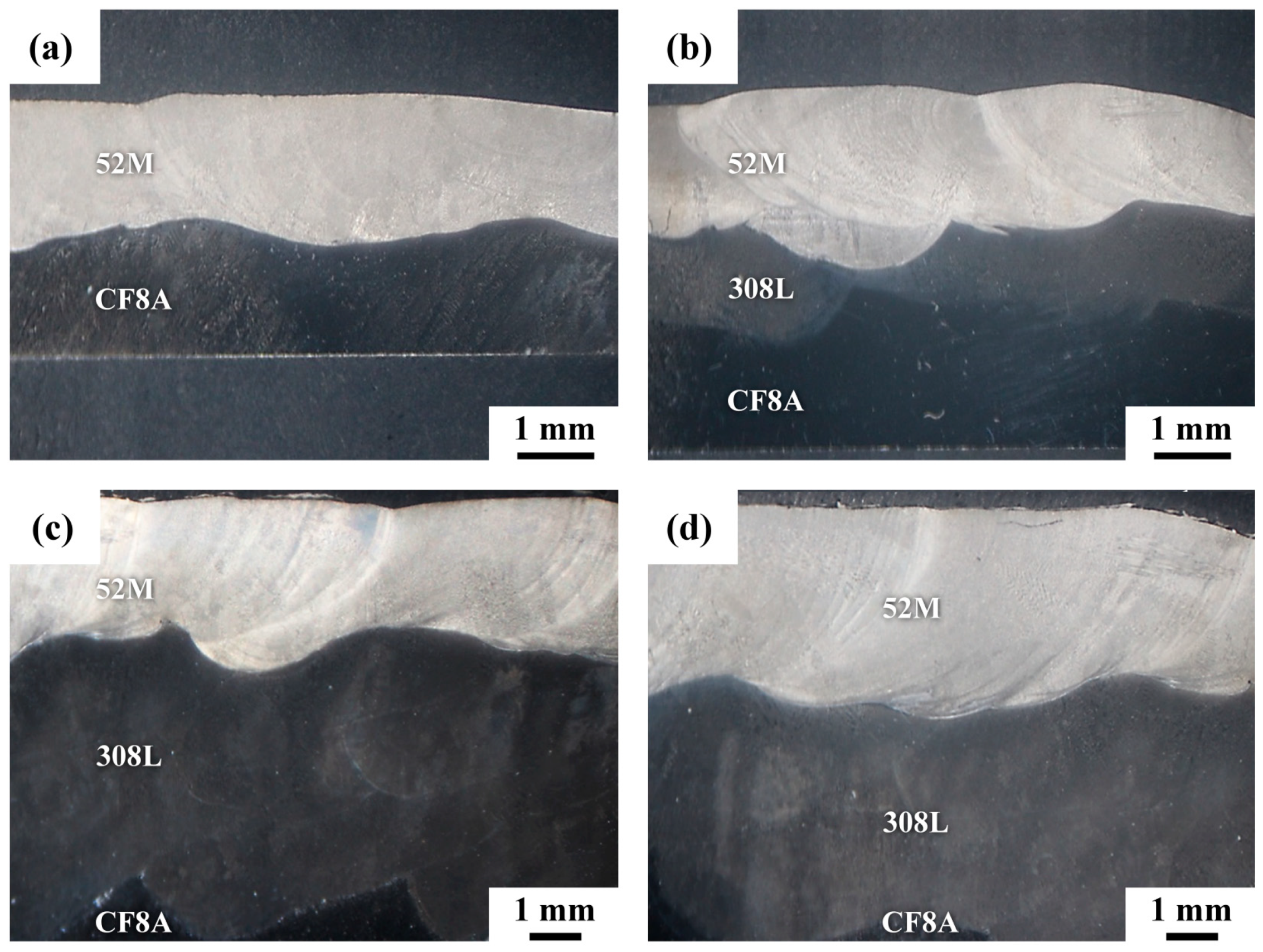
3.1. Macro-Appearance of Overlay Welds

Figure 2 shows the macro-appearance of overlay welds viewed from the top weld surface. With proper overlap of the weld beads, the overall surface of the overlay welds was quite smooth. Figure 2a,b show the surface morphologies of overlay welds deposited by using 52M and 52MSS fillers directly onto the CF8A substrate. The results indicated that hot cracks were more likely to be seen in the ending craters, especially those of the 52MSS welds. Occasionally, short fine cracks could be found in the 52MSS overlays after metallographic preparations. It was deduced that the ending craters that were concave in shape naturally had low resistance to shrinkage stress, resulting in high hot crack sensitivity. To prevent contamination with harmful elements from the CF8A substrate, 308L filler was deposited first onto the CF8A substrate as the buffer layer, followed by applying Ni-based fillers on the buffer layer. As reported in prior studies, introducing a buffer layer can lower the hot crack susceptibility of overlay welds effectively [18,19,20,21,22]. Figure 2c,d show the surface morphologies of 52M and 52MSS overlays with the 308L buffer layer. With an extra supply of filler metal during the final stage of welding, the concavity of the ending crater was alleviated. The smoother crater profile in the overlay weld was also beneficial in lowering the hot cracking tendency. In fact, only a few surface cracks appeared in the craters of the 52MSS overlay weld. As compared with the overlay welds without a buffer layer, the decreased dilution from the CF8A substrate inevitably improved the resistance to hot cracking of the overlay welds.
Typical cross-sections of the overlay welds are shown in Figure 3. Figure 3a shows the 52M overlay directly deposited on the CF8A substrate. When the feeding speed of 52M filler was 1500 mm/min, a ripple formed at the bottom of the overlays indicated the dissolution of the CF8A substrate into the 52M overlays during overlay-welding. A cross-section of the weld with a 308L buffer layer applied prior to the Ni-based fillers is displayed in Figure 3b. The buffer layer was applied at a filler-feeding speed of 1050 mm/min. Although the overall thickness of the buffer layer was not less than 2 mm, a fluctuation in the thickness of buffer layer at specific sites occurred. A thin buffer layer was associated with the risk of high dilution of the substrate during the subsequent deposition of Ni-based fillers. A macro-view of the overlay weld with the 308L feeding speed increased to 1250 mm/min and two layers applied onto the CF8A substrate before the Ni-based overlay was deposited is shown in Figure 3c. Due to the thicker buffer layer, the contamination of the Ni-based overlay by the CF8A substrate was effectively prevented. Moreover, increasing the 52M feeding speed to 1900 mm/min was also accompanied by a decrease in the observable surface cracks of the overlay, especially at the ending craters of the weld (Figure 3d).

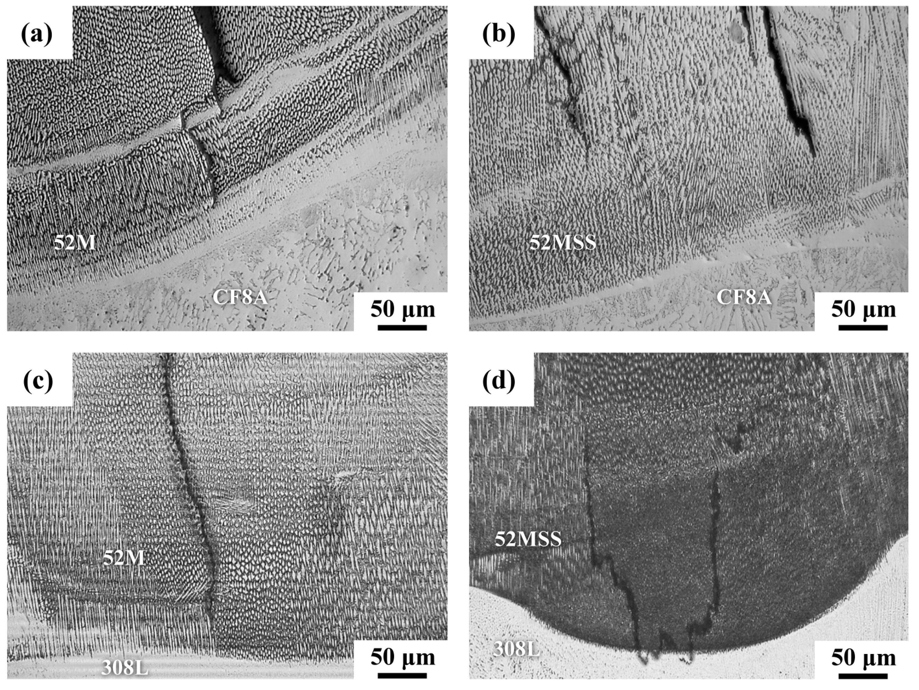
3.2. Microstructural Observations

Figure 4 presents metallographs showing the microstructures of the overlay welds. The CF8A substrate consisted of about 8% ferrite, which was in the form of coarse skeleton δ ferrite dispersed in a γ matrix. The microhardnesses of the CF8A substrate, 52M, and 52MSS overlays were about HV (Vickers hardness number) 155, 160, and 175, respectively. The hardness of 52MSS overlay was higher than that of the 52M overlay. The CF8A substrate was softer than the weld overlays. The higher hardness of the 52MSS overlay exhibited greater tensile strength than that of the 52M [25]. When Ni-based fillers were deposited directly on the CF8A substrate, cracks initiated from the interfacial region, regardless of the different fillers (Figure 4a,b). As mentioned previously, only a few surface cracks were observed in the ending craters of 52MSS overlay welds if a buffer layer was applied. In addition, top surface cracks were seldom found in the 52M overlay, even without a buffer layer. In the crater regions, the cracks also tended to grow from the Ni-filler/308L interface into the Ni-based overlays if a buffer layer was applied (Figure 4c,d). Thus, the internal cracks in the overlay, which were embedded below the top weld surface, would likely extend to the surface during long-term service.
Figure 5 presents photographs showing the detailed microstructures of the various overlay specimens. The optical microstructures of the 52M and 52MSS overlays were very similar, in that they were comprised of cellular dendrites with very fine precipitates distributed along the solidified boundaries (Figure 5a,b). SEM micrographs revealed that the cellular dendrite boundaries consisted of irregular fine precipitates and even some lamellar white phases (Figure 5c,d). As reported in prior studies, the white phases at the interdendritic boundaries were found to be rich in Ti, Nb, and Mo elements [25]. In addition, the grain boundary precipitates in the 52MSS overlay were more numerous and larger than those in the 52M overlay. It was noticed that those white phases in the 52M overlay were more likely in long island-like forms, and some aggregated into irregular morphologies (Figure 5c). By contrast, chain island-like precipitates were found to decorate the solidified boundaries of the 52MSS overlay (Figure 5d). In addition, coarse white phases were in the Chinese embroidery form, which could be related to the eutectic constituents formed during the final stage of solidification. Undoubtedly, the causes of hot cracking of the weld overlays could be associated with those white phases or precipitates at the interdendritic boundaries. As shown in Figure 1b, the top surface of sample 2 was inspected to find DDC. Grain boundary migration in the overlays did occur, as shown in Figure 5e,f. The migrated boundaries in the 52MSS overlay were more tortuous than those in the 52M overlay. The larger number of precipitates at the boundaries of the former than at those of the latter could retard or drag the motion of grain boundaries, resulting in the more tortuous migrated boundaries. After the samples were polished, those migrated boundaries were not observed. With careful section of the sample in the direction parallel to the welding direction, DDC did not occur in either sample under the welding conditions of this study.

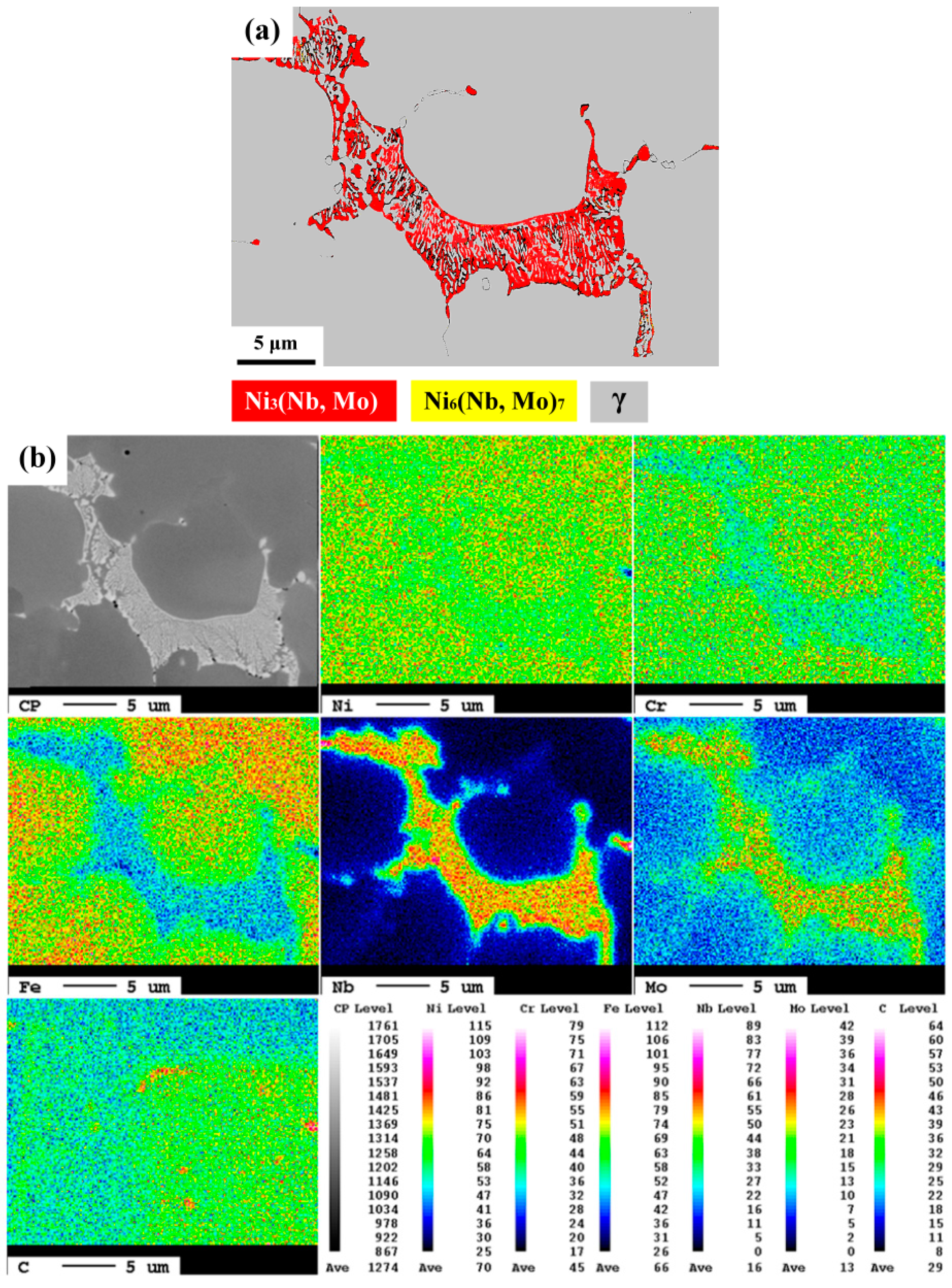
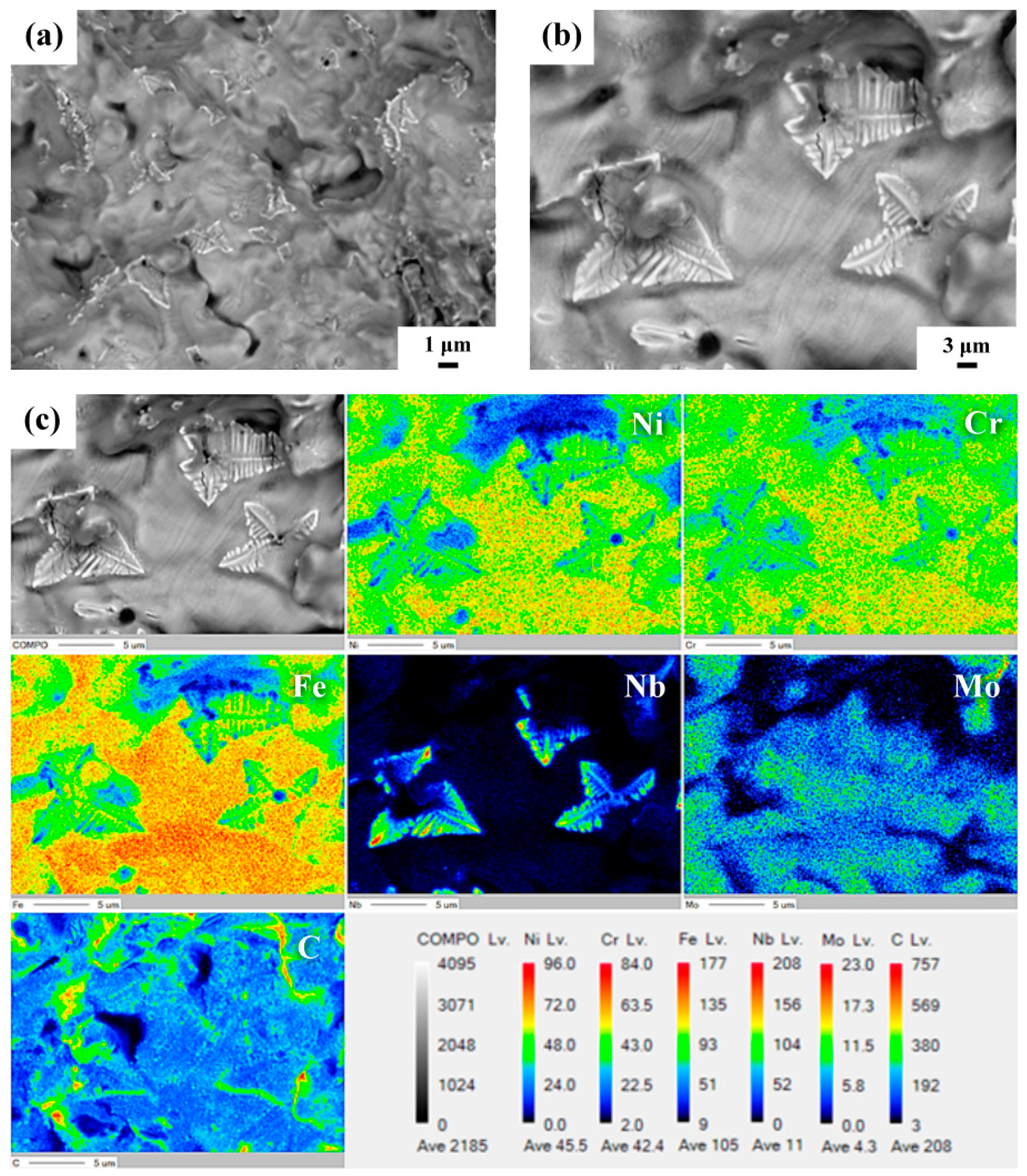
3.3. Microstructural Identifications

The fracture features of the internal cracks were investigated to distinguish hot cracking from DDC. The cracks embedded in the overlay were examined after metallographic preparations. Figure 6 shows the internal cracks present in the Ni-based overlays. Inevitably, the internal cracks propagated along the white phases in the 52M (Figure 6a) and 52MSS (Figure 6b). The detailed microstructures at the grain boundaries were chain-island in form and had a lamellar structure (Figure 6c). The appearance of partially open cracks showed that the cracked surface was comprised of numerous droplets decorated with fine precipitates in the 52MSS overlay (Figure 6d). Those precipitates in Figure 6d had nearly the same features as those in Figure 6c. Such findings confirmed that predominant solidification cracking occurred in the Ni-based overlays, particularly in 52MSS. Moreover, the backscattered electron (BSE) image showed that those white precipitates were likely associated with the segregation of heavy alloy elements to the solidified boundaries. Therefore, it was deduced that the lamellar structure on the cracked surface could be related to the eutectic constituents formed during the final stage of solidification.
After metallographic preparations, the morphologies of the solidification products were inspected by SEM in BSE image, and the chemical compositions of the white phases in the 52MSS overlay were determined by EPMA. The BSE image and EPMA elemental maps of the white phases in chain islands ahead of the internal cracks in the 52MSS overlay are displayed in Figure 7. The white phases in lamellar form at the grain boundary (Figure 7a) were expected to be eutectic micro-constituents that formed during the final solidification stage of the welding. According to the BSE image contrast (Figure 7a), heavy elements should co-segregate and participate into the final solidification products. According to the composition of the 52MSS filler, the EPMA elemental maps (Figure 7b) indicated that the eutectic colony was lean in C, Cr, Ni, and Fe elements, but rich in Nb and Mo. Those fine precipitates around the major solidification products also showed the same distributions of alloy elements as the coarse ones. The lamellar white phases were low in C content; thus, they likely were unrelated to the eutectic constituents of the γ-MC (metal carbides) solidification products.
The phase constituents of the solidified products at the grain boundaries were identified by EBSD phase mapping, and their compositions were further checked by EPMA, as shown in Figure 8. The EBSD phase map (Figure 8a) confirmed that the lamellar white phases were predominantly (Ni3(Nb,Mo)) mixed with very few (Ni6(Nb,Mo)7) intermetallics. The EPMA elemental maps (Figure 8b) indicated that the eutectic colonies were rich in Nb and Mo but lacked Ni, Fe, Cr, and C. Moreover, MC (metal carbides) were found occasionally as isolated particles but not in the lamellar structure in the overlays. Therefore, γ-Ni3(Nb,Mo) intermetallics were the major phases that formed at the grain boundaries during the final solidification stage, which were also responsible for the hot cracking of the overlay welds. Despite their difference in morphology, the grain boundary precipitates in the lamellar form had similar phase constituents. Therefore, it was deduced that the γ-Ni3(Nb,Mo) eutectics were the major causes of the hot cracking of 52M and 52MSS overlay welds.

3.4. Hot Crack Features

SEM fractographs in BSE image of opened microcracks in 52MSS craters and the associated EPMA elemental maps are displayed in Figure 9. After the microcracks were opened, the fractured surface displayed typical columnar features decorated with some terminal solidification products (Figure 9a,b). The coverings on the cracked surface had different morphologies including chain-island, leaf-like, and aligned particles. The separations between cellular dendrites were closely associated with solidification products in the overlay welds. Those terminal solidification products were more likely in lamellar structures, as shown in Figure 9b. The chemical compositions and the elemental distributions of those coverings were determined by EPMA and shown in Figure 9c. The EPMA elemental maps showed that those interdendritic precipitates had low Ni, Fe, and Cr contents but were rich in Nb. It was obvious that those lamellar precipitates did not consist of high C content. According to the EBSD analysis, it was deduced that the segregation of Nb to dendrite boundaries of the overlay weld assisted the formation of Ni3Nb intermetallics. Therefore, the formation of γ-Ni3(Nb,Mo) liquid film at the grain boundaries was responsible for the hot cracking of IN52M and 52MSS overlay welds, particularly for the 52MSS. The C map (Figure 9c) revealed the evidence of segregation of C to interdendritic boundaries. Some NbC particles and fine carbide particles were found on the fracture surface (Figure 9b). It seemed that γ-MC eutectics did not dominate the hot cracking of the Ni-base overlays in this study. However, the segregation of C to the grain boundaries could depress the final solidification temperature, and enhance the hot cracking of the overlay welds.

4. Discussion

Hot cracks were found to originate in the diluted zone near the weld interface in this work and in prior studies [18,21]. The solidification modes, microstructures, and morphologies of austenitic welds are known to be strongly affected by their compositions and Ni, Cr equivalents. To prevent hot cracking during welding, a fully austenitic weld should consist of very low concentration of impurities [36]. A drastic change in composition in the diluted zone around the weld interface occurs [18], leading to a change in solidification mode from the primary ferrite to the primary austenite mode in a dissimilar metal weld. Therefore, those impurities from the substrate were expected to initiate hot cracks at the weld interface. Applying a buffer layer was helpful in reducing the harmful impurities coming from the CF8A substrate to initiate hot cracking. Thin slices were cut parallel to the top surfaces of the overlay welds for more extensive examinations of the hot cracks in the samples with buffer layers in this study. Internal cracks were not seen in the 52M overlay, and few fine short cracks were observed in the 52MSS overlay with a buffer layer. Therefore, applying a buffer layer of sufficient thickness is necessary to prevent hot cracking of 52M and 52MSS overlay welds.
The metallographic examinations of this work confirmed that the hot cracking susceptibility of the 52MSS overlay was higher than that of the 52M overlay [34,35]. Table 2 lists the solidus and liquidus temperatures of different samples determined by DSC. It was found that the solidus temperature of the overlay was lower than that of the filler in each group. This could be related to the segregation and formation of low melting point constituents at the solidified boundaries. The lower TS (solidus temperature) also meant a greater accumulation of shrinkage strain during solidification after welding, which was detrimental to its weldability. Moreover, the results indicated that the solidification temperature range (∆TL→S) decreased in the following order: 52MSS overlay > 52MSS filler > 52M overlay > 52M filler (81, 57, 48, and 36 °C, respectively). A wider ∆TL→S temperature range of the 52MSS overlay also implied that it was more susceptible to solidification or hot cracking than other samples were.
Liquation cracking of grain boundary precipitates such as gamma prime [37], MC carbides [38], Cr–Mo borides, and intermetallics [39] is responsible for the poor weldability of the Ni-based superalloys. It is reported that two eutectic-type reactions at the terminal stages of solidification, L→(NbC-γ) and L→(Laves-γ), occur at the interdendritic boundaries during the solidification of Nb-bearing superalloys and IN 625 alloy [40,41]. Those reactions are responsible for the increased susceptibility of Nb-bearing alloys to solidification cracking. In this work, the hot cracking of 52M and 52MSS overlay welds was attributed mainly to the formation of γ-Ni3(Nb,Mo) eutectics at the boundaries during the terminal stage of solidification. Due to the greater Nb and Mo contents in the 52MSS overlay, coarser and greater amounts of microconstituents were formed at the interdendritic boundaries, thus, the hot cracking susceptibility of the 52MSS overlay was naturally higher than that of the 52M overlay. Moreover, The C maps showed the segregation of C and the formation of fine carbides on the cracked surface. The segregation of C to the grain boundaries could depress the final solidification temperature, and enhance the hot cracking of the overlay welds.

5. Summary

In this study, gas tungsten arc welding process in multiple passes was applied to deposit IN52M and 52MSS onto CF8A stainless steel. The susceptibility to hot cracking and ductility dip cracking (DDC) of the IN52M and IN52MSS overlay welds was investigated. The hot cracking tendency of the overlay welds was associated with the presence of low-melting microconstituents at the interdendritic boundaries. The formation of γ-(Ni3(Nb,Mo)) eutectics was responsible predominantly for the hot cracking of the 52M and 52MSS overlays, especially that of the 52MSS overlay. The solidification temperature range (∆TL→S) decreased in the following order: 52MSS overlay > 52MSS filler > 52M overlay > 52M filler (81, 57, 48, and 36 °C, respectively). The results also confirmed that the 52MSS overlay was more susceptible to solidification or hot cracking than the 52M overlay. Migrated grain boundaries were observed in the 52M and 52MSS overlays, but they did not induce DDC in this study.

Author Contributions

L.-W.T. and S.-L.J. organized this study. M.-Y.C., T.-J.W., and T.-C.C. worked together, and performed all the experimental tests. All authors were involved in completing the manuscript.

Funding

This research was funded by the Institute of Nuclear Energy Research, Division of Nuclear Fuels and Materials, Taiwan (Contract No. NL1070386).

Conflicts of Interest

The authors declare no conflict of interest.

References

  1. Park, J.-H.; Chopra, O.K.; Natesan, K.; Shack, W.J.; Cullen, W.H., Jr. Boric acid corrosion of light water reactor pressure vessel head materials. In Proceedings of the 12th International Conference on Environmentally Degradation of Materials in Nuclear systems—Water Reactors, Pittsburgh, PA, USA, 14–18 August 2005; pp. 459–468. [Google Scholar]
  2. Bamford, W.; Hall, J. A review of alloy 600 cracking in operating nuclear plants including alloy 82 and 182 weld behavior. In Proceedings of the 12th International Conference on Nuclear Engineering, New York, NY, USA, 25–29 April 2004; pp. 131–139. [Google Scholar]
  3. Scott, P.M.; Combrade, P. On the mechanism of stress corrosion crack initiation and growth in alloy 600 exposed to PWR primary water. In Proceedings of the 11th International Conference on Environmental Degradation of Materials in Nuclear Power System-Water Reactors, La Grange Park, IL, USA, 10–14 August 2003; pp. 29–38. [Google Scholar]
  4. Jenssen, A.; Norrgaard, K.; Lagerstroem, J.; Embring, G.; Tice, D.R. Assessment of cracking in dissimilar metal welds. In Proceedings of the 10th International Conference on Environmentally Degradation of Materials in Nuclear systems - Water Reactors; NACE International, Houston, TX, USA, 5–9 August 2001. [Google Scholar]
  5. King, C.; Frederick, G. Technical basis for Preemptive Weld Overlays for Alloy 82/182 Butt Welds in PWRs (MRP-169) Revision 1; EPRI: Palo Alto, CA, USA, 2008. [Google Scholar]
  6. Xie, Y.; Wu, Y.; Burns, J.; Zhang, J. Characterization of stress corrosion cracks in Ni-based weld alloys 52, 52M and 152 grown in high-temperature water. Mater. Charact. 2016, 112, 87–97. [Google Scholar] [CrossRef] [Green Version]
  7. Li, G.; Zhang, M.; Huang, J.; Sun, Z.; Wu, Y. A comparative study on microstructure and properties of Inconel 52M overlays deposited by laser beam and GTA cladding. Int. J. Adv. Manuf. Technol. 2015, 81, 103–112. [Google Scholar] [CrossRef]
  8. Song, T.K.; Bae, H.R.; Kim, Y.J.; Lee, K.S. Numerical investigation on welding residual stresses in a PWR pressurizer safety/relief nozzle. Fatigue Fract. Eng. Mater. Struct. 2010, 33, 689–702. [Google Scholar] [CrossRef]
  9. Huang, C.C.; Liu, R.F. Structural integrity analyses for preemptive weld overlay on the dissimilar metal weld of a pressurizer nozzle. Int. J. Press. Vessel. Pip. 2012, 90–91, 77–83. [Google Scholar] [CrossRef]
  10. Fink, C.; Zinke, M.; Keil, D. Evaluation of hot cracking susceptibility of nickel-based alloys by the PVR test. Weld. World 2012, 56, 37–43. [Google Scholar] [CrossRef]
  11. Chen, T.C.; Cheng, Y.H.; Tsay, L.W.; Shiue, R.K. Effects of grain boundary microconstituents on heat-affected zone cracks in a Mar-M004 weldment. Metals 2018, 8, 201. [Google Scholar] [CrossRef]
  12. Cheng, Y.H.; Chen, J.T.; Shiue, R.K.; Tsay, L.W. The evolution of cast microstructures on the HAZ liquation cracking of Mar-M004 weld. Metals 2018, 8, 35. [Google Scholar] [CrossRef]
  13. Chen, K.C.; Chen, T.C.; Shiue, R.K.; Tsay, L.W. Liquation cracking in the heat-affected zone of IN738 superalloy weld. Metals 2018, 8, 387. [Google Scholar] [CrossRef]
  14. Angella, G.; Barbieri, G.; Donnini, R.; Montanari, R.; Richetta, M.; Varone, A. Electron beam welding of IN792 DS: effects of pass speed and PWHT on microstructure and hardness. Materials 2017, 10, 1033. [Google Scholar] [CrossRef]
  15. Li, Q.; Lin, X.; Wang, X.; Yang, H.; Song, M.; Huang, W. Research on the grain boundary liquation mechanism in heat affected zones of laser forming repaired K465 nickel-based superalloy. Metals 2016, 6, 64. [Google Scholar] [CrossRef]
  16. Lippold, J.C.; Kiser, S.D.; DuPont, J.N. Welding Metallurgy and Weldability of Nickel-Base Alloys; John Wiley & Sons: Hoboken, NJ, USA, 2011. [Google Scholar]
  17. Hänninen, H.; Brederholm, A.; Saukkonen, T. Hot Cracking Susceptibility of Ni-base Alloy Dissimilar Metal Welds, Hot Cracking Phenomena in Welds II; Springer: Berlin, Heidelberg, 2008; pp. 171–191. [Google Scholar]
  18. Chu, H.A.; Young, M.C.; Chu, H.C.; Tsay, L.W.; Chen, C. Hot cracking susceptibility of Alloy 52M weld overlays onto CF8 stainless steel. J. Nucl. Mater. 2013, 433, 419–423. [Google Scholar] [CrossRef]
  19. Shih, Y.-J. Mitigation of hot cracking of alloy 52M overlay on cast stainless steel CF8A. Sci. Technol. Weld. Join. 2013, 18, 566–572. [Google Scholar] [CrossRef]
  20. Lin, C.-M. Relationships between microstructures and properties of buffer layer with Inconel 52M clad on AISI 316L stainless steel by GTAW processing. Surf. Coatings Technol. 2013, 228, 234–241. [Google Scholar] [CrossRef]
  21. Chu, H.A.; Young, M.C.; Chu, H.C.; Tsay, L.W.; Chen, C. The effect of Nb and S segregation on the solidification cracking of alloy 52M weld overlay on CF8 stainless steel. J. Mater. Eng. Perform. 2014, 23, 967–974. [Google Scholar] [CrossRef]
  22. Ko, G.; Seo, K.M.; Kim, H.J.; Hong, H. Characteristics of hot cracking in dissimilar joint of A690 overlay and stainless steel clad. Weld. World 2017, 61, 945–953. [Google Scholar] [CrossRef]
  23. Tsai, K.-C.; Jeng, S.-L. A feasibility study of applying SS 307Si buffer layer for mitigating the hot cracking of Ni-based weld overlay. J. Mater. Eng. Perform. 2017, 26, 3698–3709. [Google Scholar] [CrossRef]
  24. Li, G.; Lu, X.; Zhu, X.; Huang, J.; Liu, L.; Wu, Y. The segregation and liquation crackings in the HAZ of multipass laser-welded joints for nuclear power plants. J. Mater. Eng. Perform. 2017, 26, 4083–4091. [Google Scholar] [CrossRef]
  25. Jeng, S.-L.; Chang, Y.-H. The influence of Nb and Mo on the microstructure and mechanical properties of Ni–Cr–Fe GTAW welds. Mater. Sci. Eng. A 2012, 555, 1–12. [Google Scholar] [CrossRef]
  26. Zhang, X.; Li, D.-Z.; Li, Y.-Y.; Lu, S.-P. Effect of Nb and Mo on the microstructure, mechanical properties and ductility-dip cracking of Ni–Cr–Fe weld metals. Acta Metall. Sin. English Lett. 2016, 29, 928–939. [Google Scholar] [CrossRef]
  27. Hope, A.T.; Lippold, J.C. Development and testing of a high-chromium, Ni-based filler metal resistant to ductility dip cracking and solidification cracking. Weld. World 2017, 61, 325–332. [Google Scholar] [CrossRef]
  28. Ramirez, A.J.; Lippold, J.C. High temperature behavior of Ni-base weld metal: Part I. Ductility and microstructural characterization. Mater. Sci. Eng. A 2004, 380, 259–271. [Google Scholar] [CrossRef]
  29. Ramirez, A.J.; Lippold, J.C. High temperature behavior of Ni-base weld metal: Part II – Insight into the mechanism for ductility dip cracking. Mater. Sci. Eng. A 2004, 380, 245–258. [Google Scholar] [CrossRef]
  30. Ramirez, A.J.; Sowards, J.W.; Lippold, J.C. Improving the ductility-dip cracking resistance of Ni-base alloys. J. Mater. Process. Technol. 2006, 179, 212–218. [Google Scholar] [CrossRef]
  31. Chen, J.Q.; Lu, H.; Cui, W.; Chen, J.M.; Huang, Y.F. Effect of grain boundary behaviour on ductility dip cracking mechanism. Mater. Sci. Technol. 2014, 30, 1189–1196. [Google Scholar] [CrossRef]
  32. Chen, J.Q.; Lu, H.; Yu, C.; Chen, J.M.; Zhang, M.L. Ductility dip cracking mechanism of Ni–Cr–Fe alloy based on grain boundary energy. Sci. Technol. Weld. Join. 2013, 18, 346–353. [Google Scholar] [CrossRef]
  33. Wu, W.T.; Tsai, C.H. Hot cracking susceptibility of fillers 52 And 82 in Alloy 690 welding. Metall. Mater. Trans. A 1999, 30A, 417426. [Google Scholar] [CrossRef]
  34. McCracken, S.L.; Alexandrov, B.T.; Lippold, J.C.; Sowards, J.W.; Hope, A.T. Hot cracking study of high chromium nickel-base weld filler metal 52MSS (ERNiCrFe-13) for nuclear applications. In Proceedings of the ASME 2010 Pressure Vessels & Piping Division Conference, Bellevue, DC, USA, 18–22 July 2010. [Google Scholar]
  35. Yushchenko, K.; Savchenko, V.; Chervyakov, N.; Zvyagintseva, A.; Guyot, E. Comparative hot cracking evaluation of welded joints of alloy 690 using filler metals Inconel 52 And 52 MSS. Weld. World 2011, 55, 28–35. [Google Scholar] [CrossRef]
  36. Brooks, J.A.; Lambert, F.J.J. The effects of phosphorus sulfur and ferrite content on weld cracking of type 309 stainless steel. Weld. J. 1978, 57, 139–143. [Google Scholar]
  37. Ojo, O.A.; Richards, N.L.; Chaturvedi, M.C. Contribution of constitutional liquation of gamma prime precipitate to weld HAZ cracking of cast Inconel 738 superalloy. Scr. Mater. 2004, 50, 641–646. [Google Scholar] [CrossRef]
  38. Ojo, O.A.; Chaturvedi, M.C. Liquation microfissuring in the weld heat-affected zone of an overaged precipitation-hardened nickel-base superalloy. Metall. Mater. Trans. A 2007, 38, 356–369. [Google Scholar] [CrossRef]
  39. Montazeri, M.; Ghaini, F.M. The liquation cracking behavior of IN738LC superalloy during low power Nd:YAG pulsed laser welding. Mater. Charact. 2012, 67, 65–73. [Google Scholar] [CrossRef]
  40. Dupont, J.N.; Robino, C.V.; Michael, J.R.; Notis, M.R.; Marder, A.R. Solidification of Nb-bearing Superalloys: Part I. Reaction Sequences. Metall. Mater. Trans. A 1998, 29, 27852796. [Google Scholar] [CrossRef]
  41. Cieslak, M.J. The Welding and Solidification Metallurgy of Alloy 625. Weld. J. 1991, 70, 49–56. [Google Scholar]
Figure 1. Schematic diagrams showing (a) macroscopic view of overlay weld, (b) the sample 1 for hot cracking and sample 2 for ductility dip cracking (DDC) examinations.
Metals 09 00651 g001
Figure 2. Macro-appearance of overlay welds: (a) 52M, (b) 52MSS without buffer layer; (c) 52M, (d) 52MSS with buffer layer in the as-deposited condition.
Metals 09 00651 g002
Figure 3. Typical cross-sections of the overlay welds: (a) 52M without buffer layer, (b) 52M with single buffer layer, (c) 52M with double buffer layer, (d) thicker 52M with double buffer layer.
Metals 09 00651 g003
Figure 4. Optical metallographs of distinct overlay welds: (a) 52M, (b) 52MSS without buffer layer; (c) 52M, (d) 52MSS with buffer layer.
Metals 09 00651 g004
Figure 5. (a,b) Optical micrographs showing the solidified microstructures of 52M overlay oriented parallel or normal to growth direction; (c,d) SEM micrographs of 52M and 52MSS overlays showing the grain boundary microconstituents; (e,f) SEM micrographs of migrated grain boundaries (indicated by the arrows) in the 52M and 52MSS overlays.
Metals 09 00651 g005
Figure 6. Backscattered electron (BSE) images showing the internal cracks in the (a) 52M, (b) 52MSS, (c) microconstituents in the 52MSS, (d) microconstituents deposited on the cracked 52MSS overlays.
Metals 09 00651 g006
Figure 7. (a) BSE image, (b) electron probe micro-analyzer (EPMA) elemental maps of grain boundary precipitates formed ahead of the crack front in the 52MSS overlay.
Metals 09 00651 g007
Figure 8. (a) Electron backscatter diffraction (EBSD) phase map, (b) EPMA elemental maps of solidification products in the 52MSS overlay.
Metals 09 00651 g008
Figure 9. (a,b) Fracture appearance of opened hot crack, (c) EPMA elemental maps of solidification products on the cracked surface in the 52MSS overlay.
Metals 09 00651 g009
Table 1. The chemical compositions (in wt.%) of the materials used in this work.
MaterialsElements
CCrNiFeMnNbMoTiSiPSNb + Ta
CF8A0.0518.38.2Bal.1.30---0.500.0200.0060-
308L0.0120.010.0Bal.1.70-0.10-0.400.0200.0100-
52M0.0229.7Bal.8.80.700.80.050.170.110.0020.00050.14
52MSS0.02329.5Bal.8.80.312.53.500.180.110.0040.00050.01
Table 2. The solidus and liquidus temperatures of different samples determined by differential scanning calorimetry.
MaterialsTemperature (°C)
TSTL∆TL→S
52M filler1345138136
52MSS filler1342139957
52M overlay1310135848
52MSS overlay1291137881
TS: Solidus temperature; TL: Liquidus temperature; ∆TL→S: Solidification temperature range.

