Article

Laser Shock Peening: Toward the Use of Pliable Solid Polymers for Confinement

1
Laboratoire PIMM, UMR 8006, ENSAM, CNRS, CNAM, HESAM, 151 boulevard de l’Hôpital, 75013 Paris, France
2
Airbus Operation S.A.S, 316 route de Bayonne-B.P. D4101, CEDEX 9, F-31060 Toulouse, France
3
Thales Las France, 78990 Elancourt, France
4
CEA, DAM, DIF, 91297 Arpajon, France
5
Airbus Operations GmbH, Kreetslag 10, 21129 Hamburg, Germany
*
Authors to whom correspondence should be addressed.
Metals 2019, 9(7), 793; https://doi.org/10.3390/met9070793
Submission received: 20 May 2019 / Revised: 5 July 2019 / Accepted: 11 July 2019 / Published: 17 July 2019
(This article belongs to the Special Issue Laser Shock Processing and Related Phenomena)

Abstract

:
This paper presents the first extensive study of the performances of solid polymers used as confinement materials for laser shock applications such as laser shock peening (LSP) as opposed to the exclusively used water-confined regime up to now. The use of this new confinement approach allows the treatment of metal pieces needing fatigue behavior enhancement but located in areas which are sensitive to water. Accurate pressure determination in the polymer confinement regime was performed by coupling finite element simulation and experimental measurements of rear free-surface velocity using the velocity interferometer system for any reflector (VISAR). Pressure could reach 7.6 and 4.6 GPa for acrylate-based polymer and cross-linked polydimethylsiloxane (PDMS), respectively. At 7 and 4.7 GW/cm 2 , respectively, detrimental laser breakdown limited pressure for acrylate and PDMS. These results show that the pressures produced were also as high as in water confinement, attaining values allowing the treatment of all types of metals with LSP and laying the groundwork for future determination of the fatigue behavior exhibited by this type of treated materials.

1. Introduction

The first discoveries leading to the development of modern-day laser shock peening (LSP) started in the 1960s with the spread of pulsed laser technology. The study of laser interaction with different materials led to pressure measurements on a surface ablated by a pulsed laser [1]. A major breakthrough occurred in 1970 when Anderholm discovered that the pressure delivered through a laser shock could be greatly improved by confining the plasma produced by placing a quartz overlay, transparent to the laser beam, on the target [2]. At the beginning of the 1970s, studies on the effect of LSP applied on metallic targets began at the Battelle institute in Columbus, Ohio and demonstrated an improvement of mechanical properties in the treated zone [3].
From there, LSP started becoming a competitor of the conventional shot peening for the improvement of the fatigue performance of treated components, and laser peening is now one of the most effective surface pre-stressing treatments used to enhance the fatigue strength of metallic structures. The laser-shock-peening-induced compressive residual stresses offer better fatigue life properties [4] by retarding the crack growth and inhibiting the crack initiation [5,6,7]. In addition, LSP can significantly enhance the resistance of the treated components to stress corrosion [8].
Compared to the conventional shot peening, the affected depth is much larger for laser shock peening—up to ≈1.5 mm compared to ≈300 μ m for shot peening [9] of Al alloy materials. In addition, the LSP-induced work hardening is generally limited (about +10% to +30%) compared to conventional shot peening [10]. This can be explained by the fact that the loading duration is very short, which consequently does not allow the activation of all the sliding systems of the material and thus generates fewer cross dislocations. Only cyclic hardening materials such as 304L and 316L have their hardness and their level of residual stresses increase with impact repetition. Nevertheless, it is not possible to draw conclusions regarding the amplitude of the induced compressive residual stresses, given that contradictions exist in the literature. Therefore, conventional shot peening may be unfavorable over a material’s lifetime due to controlled deformation loading (high cycle thermal loading), reducing the beneficial effects of compressive residual stresses. For laser shock, such a risk can be avoided because of the low work hardening.
Today, LSP at an industrial scale is mainly applied in aeronautics for the treatment of sensitive areas on certain parts to increase their lifespan. Water is the usual confining material because it is cheap, transparent to the laser, and ensures contact with surfaces. Other areas are developing quickly toward industrial applications such as the treatment of parts produced by additive manufacturing. LSP treatment of these types of materials allows more shaping and forming possibilities as well as shape correction treatment due to the highly controlled nature of the process compared to conventional shot peening [10,11]. Coupled with the deeper levels of residual stress produced, it has shown to be highly cost effective despite its higher operating cost compared to conventional shot peening.
One of the obstacles to extending LSP’s applications is the impossibility of using water in a reactive atmosphere or near electronic devices. A solution to this issue should be a solid material, as demonstrated by the pioneering work on laser shock [2]. However, the use of rigid glasses for the treatment of pieces presenting complex geometries such as the ones encountered in the aeronautics industry is impossible. In contrast, a soft polymer confinement, with its adaptability, shaping possibilities, and wide range of formulations and properties, is an ideal candidate for this type of need. Laser shock peening with polymer confinement has been studied only by Hong et al. [12]. Authors evaluated only the influence of the confining medium used on mechanical impedance, without carrying out a complete investigation of the performances exhibited by these materials.
This paper presents a study concerning the use of polymers for laser shock applications. It focuses on the capability of materials to be transparent to a laser beam at high intensity and to generate a high-pressure plasma when used for the laser shock peening process in a confined regime and without a thermal coating. Plasma pressure is the driving force of the process for evaluating the range of materials which can be processed and the boundary limit for simulation. In the case of confinement in specific conditions, only experimental approaches can determine this key parameter of LSP. We present optical transmission and the characterization of plasma pressures produced by the laser in a confined regime with a choice of polymer confinements (i.e., acrylate and polydimethylsiloxane). Experiments were performed from rear free-surface velocity measurements using the velocity interferometer system for any reflector (VISAR) on pure aluminum foils coupled with numerical simulations. Results are compared to the pressure produced with water confinement interaction. The first part of this paper presents the experimental setup and methodology, while the second part is dedicated to results and discussion.

2. Materials and Methods

Figure 1 presents the experimental setup and methods used to determine plasma pressure from the velocity profile measured by VISAR.
The velocity profile was reproduced using a finite element (FE) model in which the plasma pressure was adjusted as an input condition. A direct correlation between rear free-surface velocity and the maximum pressure of the plasma was also extracted to provide fast signal analysis.

2.1. Material

The choice of the polymers was based on a few criteria in order for them to be able to deliver good results when used for LSP; namely, good optical transmission to the laser wavelength at high laser intensity, and the capability to generate sufficient pressures. Two polymers fulfilling these conditions were chosen for use as confining materials for the study. The first one was an acrylate-based tape with a thickness of 1 mm . The second one was a cross-linked PDMS with a thickness of 2 mm. Both can be defined as pressure-sensitive adhesives [13], allowing an easy bonding and debonding of the confining material to the target.
For pressure determination, the targets chosen were pure aluminum foils 99.00% from Goodfellows company (AL000645, Coraopolis, PA, USA) with a thickness of 1 mm. Aluminum is a material of choice for its well-defined properties. The thickness was chosen as a way to separate the first peak from the velocity profile from the second peak caused by the shock wave going back and forth inside the material. To ensure contact between the polymer and the aluminum target, every potential bubble was pushed away by applying low pressure on the adhesive. For the water-confined regime, a water droplet was apposed on the surface of the aluminum target. For each confinement and each laser intensity used, three samples were tested to minimize potential error and ensure reproducibility of the results.

2.2. Laser

The laser shots were performed with the Hephaïstos facility at PIMM (Laboratory for Processes and Engineering in Materials and Mechanics, Paris, France). The platform is equipped with a Gaïa HP laser from THALES (Elancourt, France). It is composed of two Nd:YAG synchronized or delayed lasers, both emitting at 532 nm. It delivers up to 14 J with a Gaussian temporal profile with a full width half-maximum (FWHM) of 9 ns. The laser spot diameter is 3 mm through a diffractive optical element (DOE) and lens with a focal length of 148 mm [14,15]. The parameters chosen and the range of laser intensity covered by this study are standard parameters for laser peening applications such as fatigue behavior improvement and the reduction of crack propagation by the induction of compressive residual stress. Energy and pulse duration were measured shot by shot. The spatial profile was measured every day.
Figure 2 shows a typical image and corresponding profile of the laser spot at the location of the target, demonstrating a uniformity of intensity below 6%. With these laser parameters, the power density reached up to 13 GW/cm 2 to achieve the breakdown threshold for all materials, which is the physical limit of the process.

2.3. Transmission Measurements

Optical transmission measurements of the polymer were performed using a calorimeter (QE50LP-H-MB-QED, Gentec, Québec, QC, Canada) located on the back of the sample holder used for the laser shock. The transmission was calculated from the difference of energy with or without material. The incident energy was chosen for a power density below the laser threshold (0.2 GW/cm 2 ).

2.4. VISAR

The rear free-surface velocity of pure aluminum foils was measured with VISAR [16]. It is an optical diagnostic tool allowing the characterization of shock waves via the obtention of the back face velocity of the sample. It is a non-contact acquisition method which can be used with water or solid confinement. The device is a Michelson-type interferometer measuring the Doppler shift in the wavelength of a probe laser reflected on the rear free surface of a target which is moved as a result of the induced shock wave.
The PIMM VISAR is composed of two main parts: the laser probe, which is a continuous-wave laser (532 nm, 5 W) from the Coherent company (Santa Clara, CA, USA), and a home-made interferometer. The laser probe is focused on the back face of the target on the center of the laser spot of the incident laser (Figure 1). The wavelength shift induced by the rear free-surface deformation with the shock-wave propagation is then transmitted to the interferometer part, where the signal interferes with itself. This device has already been used and described for plasma characterization in the direct regime [17] and in the water-confined regime [18].

2.5. Simulation

To determine plasma pressure profiles, experimental rear free-velocity profiles were predicted using simulation. The laser shock propagation simulation was carried out using the commercial FE code ABAQUS 6.14 [19]. A 2D axisymmetric model was developed. Since laser shock is a high-speed process, an explicit solver is used while considering the dynamic effects.

2.5.1. Target Geometry and Boundary Conditions

Figure 3 and Figure 4 respectively show the target configuration and the mesh used for simulation. The target was modeled as a planar shell with a 1 mm width and a 7.5 mm length. It was meshed by means of CAX4R elements (Continuum, 4-node bilinear axisymmetric, quadrilateral, reduced integration, hourglass control). To improve the accuracy of the FE solutions, a refinement mesh was used in the treated area with the use of a BIAS function in the X direction (Figure 4). As the element dimensions decreased, the obtained results became more stable. A decrease between experimental and numerical rear free-velocity profiles as observed. The treated region was refined with small elements of 1 μ m × 1 μ m dimensions. For the boundary condition, one node of the bottom surface was fixed (Figure 3).

2.5.2. Constitutive Material Model

For shock produced by laser-induced high strain rate (i.e., up to 10 6 s 1 ), the appropriate behavior law of the treated target must consider the effect of the high strain rate. In this context, the Johnson–Cook constitutive model [20] was used. In this model, the Von Mises yield criterion is defined as:
σ = ( σ y + K ϵ p n ) 1 + C l n ϵ ˙ ϵ 0 ˙ 1 T T 0 T m e l t T 0 .
The first part describes the strain-hardening effect. The second part characterizes the strain rate effect. The last part of the Johnson–Cook constitutive law associates the stress with material temperature evolution during the plastic deformation. σ y is the yield stress, B is the hardening modulus. It encompasses the second member of the above mentioned equation, ϵ p is the equivalent plastic deformation, n is the hardening coefficient, C is the strain rate sensitivity parameter, ϵ ˙ is the strain rate during the process, ϵ 0 ˙ is the reference strain rate, T m e l t is the fusion temperature, T 0 is the room temperature, E is Young’s modulus, and ν is Poisson’s ratio.
In the present study, a preliminary simulation using CAX4RT elements (Continuum, A 4-node thermally coupled axisymmetric quadrilateral, bilinear displacement and temperature, reduced integration, hourglass control) confirmed that the thermal softening effect could be neglected (for the case of laser intensity I = 2.7 GW/cm 2 , plasma pressure FWHM equal to 18 ns, and spot size of 3 mm). In fact, the local temperature increases due to the plastic deformation and the wave propagation did not have a significant influence on the rear free velocity. For this reason, the thermal part in Johnson–Cook’s constitutive law was neglected [21]. For pure aluminum, Table 1 [22] gives the Johnson–Cook parameters used for the simulation.

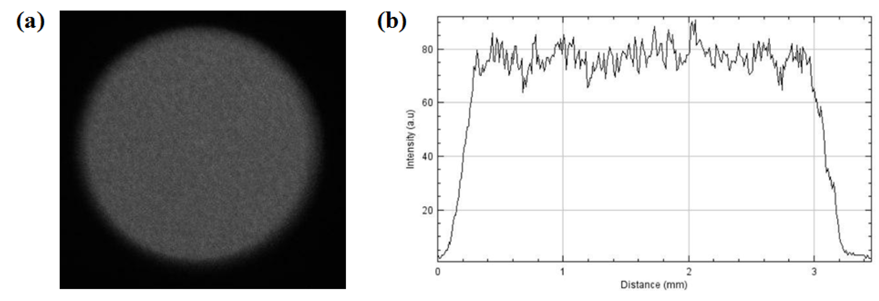
2.5.3. Spatial and Temporal Pressure Profiles

To generate spatial and temporal pressure profiles P = f ( x , y , t ) , a VDOLAD subroutine was used. The P ( t ) profiles given in Figure 5 [23] were adjusted to provide coherence between the experimental and the numerical results. The P ( x , y ) distribution was obtained (Figure 6) from beam analysis. The intensity profile from Figure 2b, obtained through a camera, was used to generate the P ( x , y ) distribution. Previous work on the subject showed the equivalence between maximum pressure and intensity [18,24]. Preliminary simulation showed that modulation had no effect on the rear free-velocity profile.

3. Results and Discussion

3.1. Transmission

Table 2 presents the optical transmission of acrylate and PDMS used for the confined laser interaction. It shows that acrylate and PDMS exhibited very good transmissions of 0.92 and 0.82, respectively. This confirms that they should be good candidates for applications. The corresponding absorption can be accounted for by following the incident power density. For the water-confined regime, no incident energy loss was considered since water is transparent at the wavelength used [25].

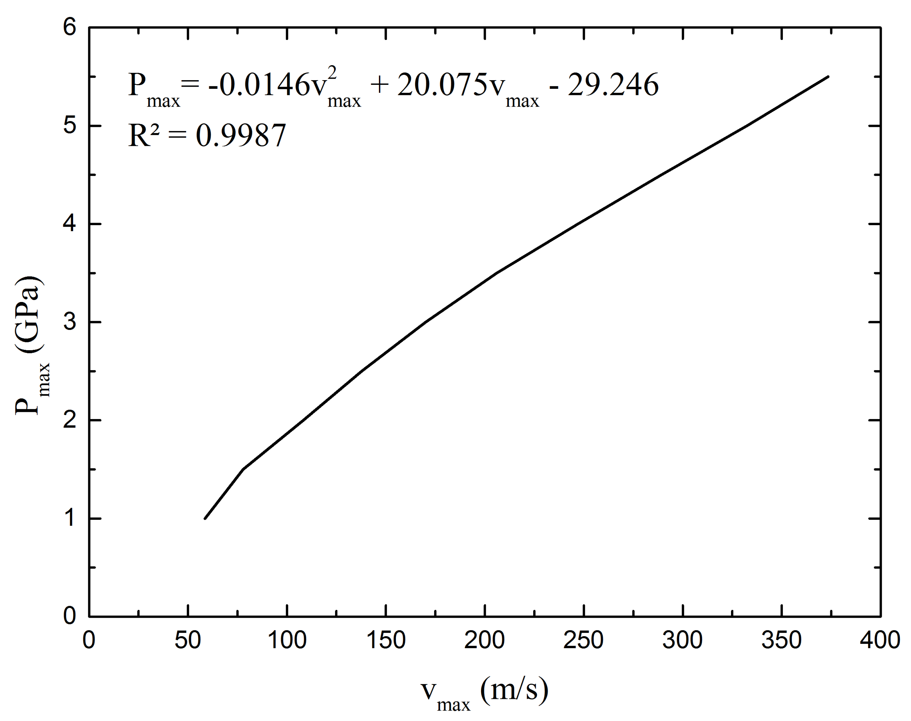
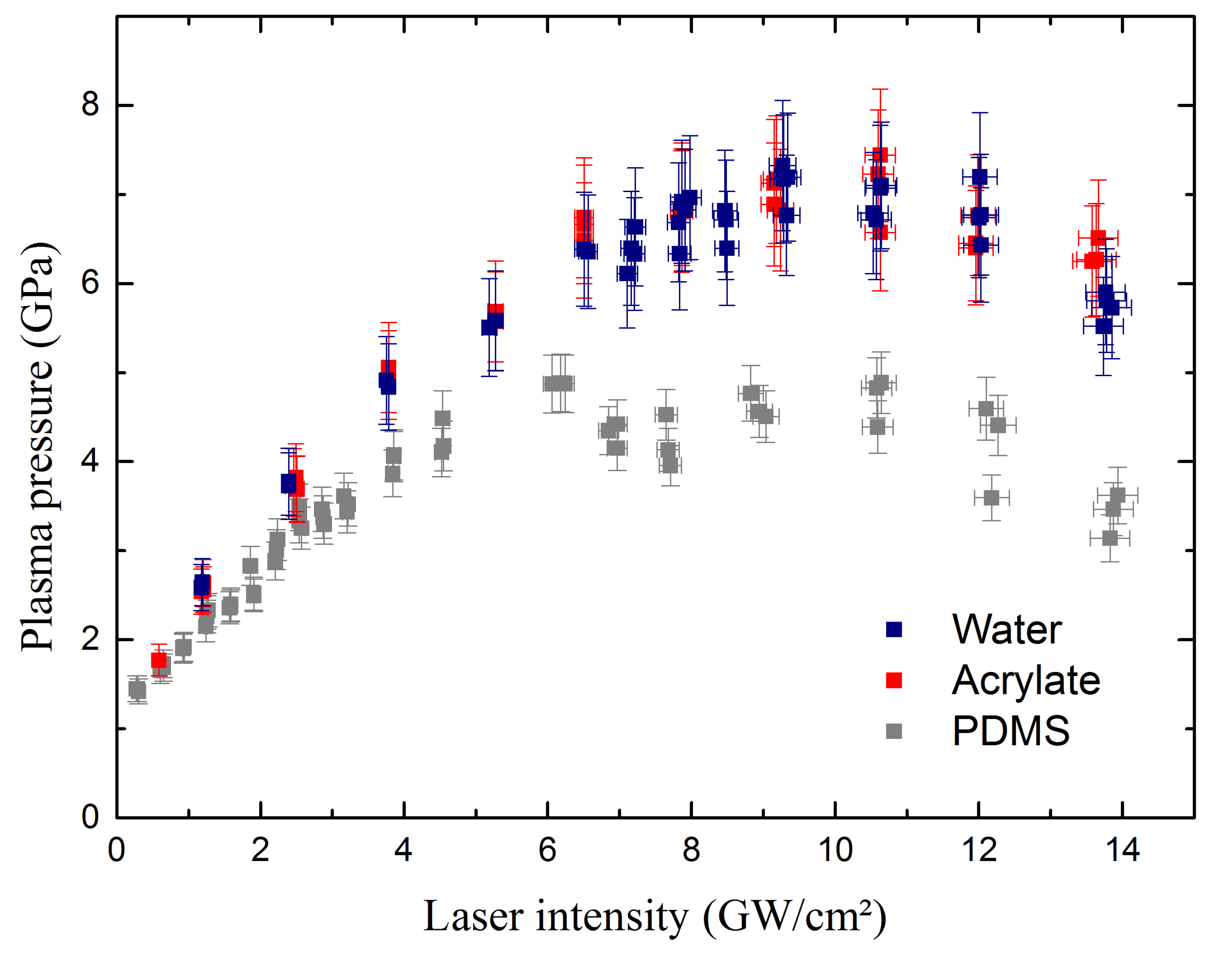
3.2. Pressure Measurement

Figure 7 presents a comparison of the rear free-velocity profile of the aluminum target in the water-confined regime at 2.7 GW/cm 2 measured with VISAR with the values obtained by simulation. The velocity profile presented two peaks corresponding respectively to the first and second occurrences of the shock wave at the rear surface of the target.
On the front shock, an inflection of the velocity corresponded to the elastic precursor at 38 m/s which equates to a Hugoniot limit P H of 0.312 GPa. We could calculate the dynamic yield stress using the following formula [26]:
σ 0 D y n = P H 1 2 ν 1 ν .
This calculation yields 0.179 GPa, which is in agreement with value previously determined in Table 1 [22]. The simulation agreed very well with the experiments for both peaks. The corresponding maximum plasma pressure, denoted as P m a x , was 3.252 GPa. Simulation showed a negative peak (25 m/s) at the end of release at 300 ns. This corresponds to effects in relation with the edge of the spatial profile [27], which are very sensitive to pressure gradients.
From the simulation, the maximum pressure of plasma P m a x could be related to the maximum velocity of the first peak ( v m a x ) measured by VISAR, as shown in Figure 8:
P m a x ( G P a ) = 0 . 01456 v m a x ( m / s ) 2 20 . 075 v m a x ( m / s ) 29 . 246 .
Compared to previous results [18], this includes shock-wave attenuation depending on the incident pressure and target thickness.
Figure 9 presents typical rear free-velocity profiles at 2.7 GW/cm 2 for water as well as acrylate and PDMS polymeric confining materials. Figure 9 focuses on the first occurrence of the laser shock wave. The global shape was similar for the three materials: both the inflection on the shock front due to elastic precursor and the FWHM (55 ns) were alike. Some differences were highlighted in the end of the relaxation in relation to edge effects. However, maximum velocities v m a x were different, showing 237 m/s, 217 m/s, and 187 m/s for water, acrylate, and PDMS respectively. From rear free-velocity profiles, corresponding P m a x values were calculated from the incident power densities ranging from 0.22 GW/cm 2 to 12.50 GW/cm 2 . They are gathered in Figure 10 for water, acrylate, and PDMS.
For the three confining materials, the data can be separated in two parts. In the first part, pressure increased with the incident power density, and in the second part the pressure saturated due to the detrimental effect of plasma breakdown of the material confinement [28]. The power density for which the breakdown limits the plasma pressure of a confining material is called the breakdown threshold. These are reported with maximum pressure in Table 3.
The acrylate and water confinements exhibited the same pressures up to 2.3 GW/cm 2 . At higher intensities, the acrylate produced slightly higher pressures, respectively 6.5 GPa at 6.02 GW/cm 2 and 6.4 GPa at 6.53 GW/cm 2 . The breakdown threshold was 7 GW/cm 2 for both confinements, and saturating pressures were produced at 7.6 GPa for the acrylate confinement and 7 GPa for water.
As expected with its optical transmission, the PDMS confinement exhibited pressures that were slightly lower than water and acrylate confinements, respectively 4.25 GPa at 3.50 GW/cm 2 , 4.90 GPa at 3.75 GW/cm 2 , and 4.98 GPa at 3.50 GW/cm 2 . The breakdown threshold was also lower at 4.7 GW/cm 2 , producing a maximum pressure of 4.6 GPa.
The chemical composition of the polymers can influence the breakdown threshold. Following this, the higher optical absorption of the PDMS favored material damage initiation compared to the acrylate confining medium. In fact, polymer damage was observed regardless of the polymer confinement used when high laser intensities were applied, typically when going higher than 3 GW/cm 2 for the acrylate confinement, which seemed to be perfectly transparent except for the laser energy loss at the interfaces. With growing damages, plasma breakdown can initiate on defects, thus lowering the breakdown threshold. The confined plasma composition is a mix, coming from the contribution of the aluminum target and the polymer confinement material through ablation and plasma heating, respectively [29]. Maximum plasma pressures were also higher than previously published by Berthe in [18,30]. The difference could be due to the better laser spatial profile obtained by using a DOE and the simulation of rear free-surface velocity on the range of incident power density instead of using a constant attenuation. The present results clearly indicate the capability of polymers to reach pressures equivalent to water confinement. However, efforts must be made concerning the adhesion and mechanical properties of polymers for LSP configuration using high repetition rate shot without coatings by varying chemical composition and manufacturing parameters.

4. Conclusions

This papers presents for the first time pressure measurements in a polymer confinement regime for 9 ns pulse duration at 532 nm wavelength up to 12.5 GW/cm 2 corresponding to the current laser parameters of LSP. Pressures were determined by coupling FE simulation and experimental measurements of rear free-velocity performed with VISAR.
  • Simulation and experiment coupling allowed accurate pressure measurements and full time and spatial determination of boundary limits for process modeling.
  • The pressures generated with acrylate were as high as those produced in the water confinement regime, up to 7 GPa, while reaching 4.6 GPa for PDMS.
  • A breakdown phenomenon occurred at 7 GW/cm 2 for the water and acrylate confinements while it happened at around 4.7 GW/cm 2 for the PDMS confinement.
  • Results demonstrate that LSP with confinement polymer allows the treatment of all types of metals, from low to high elastic limit material. [31].
Therefore, solid polymer confinements are an alternative to water for laser shock applications such as LSP. Further works will concern:
  • The influence of polymer chemical composition on plasma breakdown (extended to infrared wavelength)
  • Plasma physics at the metal/polymer interface as well as the plasma composition.
  • Optimization of polymer mechanical and adhesive properties for high-repetition-rate processing.

Author Contributions

This work was supervised by L.B. The experiments on Hephaistos’ facility were conducted by C.L.B., A.R., M.S.-B. and L.B., with Y.R.’s technical support. The design and manufacture of the polymers were done by B.F., M.G. and C.L.B. The simulations were made by R.S. under the supervision of L.M., L.V., R.E. and S.V. and D.F. participated in the exploitation and design of the Hephaistos experiments.

Funding

This study was supported by the Authors’ affiliate companies (Airbus and Thales) and institutions (CEA, CNRS, and ENSAM) and Agence pour la Recherche Forge Laser.

Conflicts of Interest

Authors declare no conflict of interest.

References

  1. Askar’yan, G.A.; Moroz, E.M. Pressure on Evaporation of Matter in a Radiation Beam. Sov. J. Exp. Theor. Phys. 1963, 16, 1638. [Google Scholar]
  2. Anderholm, N. Laser-generated stress waves. Appl. Phys. Lett. 1970, 16, 113–115. [Google Scholar] [CrossRef]
  3. Fairand, B.P.; Wilcox, B.A.; Gallagher, W.J.; Williams, D.N. Laser shock-induced microstructural and mechanical property changes in 7075 aluminum. J. Appl. Phys. 1972, 43, 3893–3895. [Google Scholar] [CrossRef]
  4. Peyre, P.; Fabbro, R.; Merrien, P.; Lieurade, H. Laser shock processing of aluminium alloys. Application to high cycle fatigue behaviour. Mater. Sci. Eng. A 1996, 210, 102–113. [Google Scholar] [CrossRef]
  5. Pavan, M.; Furfari, D.; Ahmad, B.; Gharghouri, M.; Fitzpatrick, M. Fatigue crack growth in a laser shock peened residual stress field. Int. J. Fatigue 2019, 123, 157–167. [Google Scholar] [CrossRef]
  6. Dhakal, B.; Swaroop, S. Review: Laser shock peening as post welding treatment technique. J. Manuf. Process. 2018, 32, 721–733. [Google Scholar] [CrossRef]
  7. Sun, R.; Li, L.; Guo, W.; Peng, P.; Zhai, T.; Che, Z.; Li, B.; Guo, C.; Zhu, Y. Laser shock peening induced fatigue crack retardation in Ti-17 titanium alloy. Mater. Sci. Eng. A 2018, 737, 94–104. [Google Scholar] [CrossRef]
  8. Peyre, P.; Scherpereel, X.; Berthe, L.; Carboni, C.; Fabbro, R.; Béranger, G.; Lemaitre, C. Surface modifications induced in 316L steel by laser peening and shot-peening. Influence on pitting corrosion resistance. Mater. Sci. Eng. A 2000, 280, 294–302. [Google Scholar] [CrossRef]
  9. Peyre, P.; Fabbro, R. Laser shock processing: A review of the physics and applications. Opt. Quantum Electron. 1995, 27, 1213–1229. [Google Scholar] [CrossRef]
  10. Hackel, L.; Rankin, J.R.; Rubenchik, A.; King, W.E.; Matthews, M. Laser peening: A tool for additive manufacturing post-processing. Addit. Manuf. 2018, 24, 67–75. [Google Scholar] [CrossRef]
  11. Maamoun, A.; Elbestawi, M.; Veldhuis, S. Influence of shot peening on AlSi10Mg parts fabricated by additive manufacturing. J. Manuf. Mater. Process. 2018, 2, 40. [Google Scholar] [CrossRef]
  12. Hong, X.; Wang, S.; Guo, D.; Wu, H.; Wang, J.; Dai, Y.; Xia, X.; Xie, Y. Confining medium and absorptive overlay: Their effects on a laser-induced shock wave. Opt. Lasers Eng. 1998, 29, 447–455. [Google Scholar] [CrossRef]
  13. Creton, C. Pressure-sensitive adhesives: an introductory course. MRS Bull. 2003, 28, 434–439. [Google Scholar] [CrossRef]
  14. Bardy, S.; Aubert, B.; Berthe, L.; Combis, P.; Hébert, D.; Lescoute, E.; Rullier, J.L.; Videau, L. Numerical study of laser ablation on aluminum for shock-wave applications: development of a suitable model by comparison with recent experiments. Opt. Eng. 2016, 56, 011014. [Google Scholar] [CrossRef] [Green Version]
  15. Sagnard, M.; Berthe, L.; Ecault, R.; Touchard, F.; Boustie, M. Development of the symmetrical laser shock test for weak bond inspection. Opt. Laser Technol. 2019, 111, 644–652. [Google Scholar] [CrossRef]
  16. Barker, L.; Hollenbach, R. Laser interferometer for measuring high velocities of any reflecting surface. J. Appl. Phys. 1972, 43, 4669–4675. [Google Scholar] [CrossRef]
  17. Tollier, L.; Fabbro, R.; Bartnicki, E. Study of the laser-driven spallation process by the velocity interferometer system for any reflector interferometry technique. I. Laser-shock characterization. J. Appl. Phys. 1998, 83, 1224–1230. [Google Scholar] [CrossRef]
  18. Berthe, L.; Fabbro, R.; Peyre, P.; Tollier, L.; Bartnicki, E. Shock waves from a water-confined laser-generated plasma. J. Appl. Phys. 1997, 82, 2826–2832. [Google Scholar] [CrossRef]
  19. Hibbitt, Karlsson, & Sorensen. ABAQUS/Explicit: User’s Manual; Hibbitt, Karlsson and Sorenson Incorporated: New York, NY, USA, 1998; Volume 1. [Google Scholar]
  20. Johnson, G.R. A constitutive model and data for materials subjected to large strains, high strain rates, and high temperatures. In Proceedings of the 7th International Symposium on Ballistics, The Hague, The Netherlands, 19–21 April 1983; pp. 541–547. [Google Scholar]
  21. Hfaiedh, N.; Peyre, P.; Song, H.; Popa, I.; Ji, V.; Vignal, V. Finite element analysis of laser shock peening of 2050-T8 aluminum alloy. Int. J. Fatigue 2015, 70, 480–489. [Google Scholar] [CrossRef]
  22. Cuq-Lelandais, J.P. Etude du Comportement Dynamique de Matériaux Sous Choc Laser Subpicoseconde. Ph.D. Thesis, ISAE-ENSMA Ecole Nationale Supérieure de Mécanique et d’Aérotechique, Poitiers, France, 2010. [Google Scholar]
  23. Fabbro, R.; Fournier, J.; Ballard, P.; Devaux, D.; Virmont, J. Physical study of laser-produced plasma in confined geometry. J. Appl. Phys. 1990, 68, 775–784. [Google Scholar] [CrossRef]
  24. Peyre, P.; Berthe, L.; Scherpereel, X.; Fabbro, R.; Bartnicki, E. Experimental study of laser-driven shock waves in stainless steels. J. Appl. Phys. 1998, 84, 5985–5992. [Google Scholar] [CrossRef]
  25. Pope, R.M.; Fry, E.S. Absorption spectrum (380–700 nm) of pure water. II. Integrating cavity measurements. Appl. Opt. 1997, 36, 8710–8723. [Google Scholar] [CrossRef] [PubMed]
  26. Peyre, P.; Berthe, L.; Vignal, V.; Popa, I.; Baudin, T. Analysis of laser shock waves and resulting surface deformations in an Al–Cu–Li aluminum alloy. J. Phys. D Appl. Phys. 2012, 45, 335304. [Google Scholar] [CrossRef]
  27. Boustie, M.; Cuq-Lelandais, J.; Bolis, C.; Berthe, L.; Barradas, S.; Arrigoni, M.; De Resseguier, T.; Jeandin, M. Study of damage phenomena induced by edge effects into materials under laser driven shocks. J. Phys. D Appl. Phys. 2007, 40, 7103. [Google Scholar] [CrossRef]
  28. Sollier, A.; Berthe, L.; Fabbro, R. Numerical modeling of the transmission of breakdown plasma generated in water during laser shock processing. EPJ Appl. Phys. 2001, 16, 131–139. [Google Scholar] [CrossRef]
  29. Wu, B.; Shin, Y.C. A self-closed thermal model for laser shock peening under the water confinement regime configuration and comparisons to experiments. J. Appl. Phys. 2005, 97, 113517. [Google Scholar] [CrossRef]
  30. Berthe, L.; Courapied, D.; El Karnighi, S.; Peyre, P.; Gorny, C.; Rouchausse, Y. Study of laser interaction in water flow confinement at high repetition rate. J. Laser Appl. 2017, 29, 042006. [Google Scholar] [CrossRef] [Green Version]
  31. Peyre, P.; Fabbro, R.; Berthe, L.; Scherpereel, X.; Bartnicki, E. Laser-shock processing of materials and related measurements. In Proceedings of the High-Power Laser Ablation, Santa Fe, NM, USA, 14 September 1998; Volume 3343, pp. 183–194. [Google Scholar]
Figure 1. Setup used in the Hephaïstos platform to realize the pressure measurements. VISAR: velocity interferometer system for any reflector.
Metals 09 00793 g001
Figure 2. (a) Spatial shape and (b) intensity profile for a 3-mm laser spot with a diffractive optical element (DOE) at the Hephaïstos facility.
Metals 09 00793 g002
Figure 3. Target used for the laser shock peening (LSP) finite element (FE) modeling: (a) geometry and (b) 2D axisymmetric FE model.
Metals 09 00793 g003
Figure 4. Mesh refinement used for the LSP simulation.
Metals 09 00793 g004
Figure 5. P ( t ) used for the simulation.
Metals 09 00793 g005
Figure 6. P ( x , y ) distribution simulation obtained from the intensity profile from Figure 2b.
Metals 09 00793 g006
Figure 7. Simulated and experimental rear free-velocity profiles of a water-confined laser shot on 1-mm-thick aluminum at 2.7 GW/cm 2 with a laser spot diameter of 3 mm.
Metals 09 00793 g007
Figure 8. Maximum pressure of the plasma extracted from simulation as a function of the maximum velocity developed by the laser shock process depending on the rear free-surface velocity obtained with VISAR measurement.
Metals 09 00793 g008
Figure 9. Velocity profiles with a laser focal diameter of 3 mm, an incident power density of 2.7 GW/cm 2 , and a 1-mm-thick aluminum target for water, acrylate, and PDMS confinements.
Metals 09 00793 g009
Figure 10. Pressure measurements obtained from the rear free-surface velocity measured with VISAR for the three different confinements: water, acrylate, and PDMS.
Metals 09 00793 g010
Table 1. Parameters used for the Johnson–Cook material model with an aluminum target (99.00%) [22].
Material σ y (GPa)B (GPa)nC ϵ 0 ˙ E (GPa) ν
Aluminum0.1290.20.450.030.01690.33
Table 2. Optical transmission of acrylate and PDMS at 532 nm.
ConfinementsTransmission
Acrylate0.92
PDMS0.82
Table 3. Breakdown thresholds and maximum pressures extracted from Figure 10.
Confinement WaterAcrylatePDMS
Breakdown threshold(GW/cm 2 )774.7
Maximum pressure(GPa)77.64.6

