Article

Abrasive Waterjet Cutting of Clad Composite for Achieving Minimal Cut Quality Difference Between Constituent Layers

by
Kashif Ishfaq
1,*,
Naveed Ahmad
1,2,
Nadeem Ahmad Mufti
1,
Muhammad Qaiser Saleem
1 and
Abdulrahman M. Al-Ahmari
2
1
Department of Industrial and Manufacturing Engineering, University of Engineering and Technology Lahore, Lahore 548900, Pakistan
2
Raytheon Chair for Systems Engineering, Advanced Manufacturing Institute, King Saud University, Riyadh 11421, Saudi Arabia
*
Author to whom correspondence should be addressed.
Metals 2019, 9(7), 754; https://doi.org/10.3390/met9070754
Submission received: 3 June 2019 / Revised: 24 June 2019 / Accepted: 25 June 2019 / Published: 4 July 2019

Abstract

:
Clad composites have emerged as a suitable choice to augment the industrial needs due to having a combination of different properties. The accurate cutting is challenging due to the heterogeneous nature of the composite. Conventionally, thermal cutting (plasma/gas) techniques are commonly employed which provide poor cut quality, deeper heat affected zones and demand additional finishing operations. Therefore, this research evaluates the potential of abrasive water jet cutting (AWJC) as a proficient substitute for the cutting of stainless-clad-steel composite in terms of surface quality. However, it is difficult to produce a similar level of surface finish at both the layers because the constituent layers have different mechanical properties. The effect and significance of four important AWJC parameters on cut quality are examined through statistical analyses. Optical and scanning electron microscopic analyses are further provided as evidence of the reported results. Optimal settings are also developed using a weighted signal-to-noise ratio technique which can provide minimal roughness at each layer. Moreover, using the optimal settings, a similar level of surface finish has been achieved for both the layers with a difference of just 0.03 µm between the constituent layers.

1. Introduction

Layered composites are being widely employed in manufacturing due to having a combination of different properties. The set of properties generated after the clad development are supposed to be not achievable by a single material of that clad. Exclusive features like higher strength to weight ratio, corrosion resistance, remarkable fatigue and endurance limit are offered by their use [1]. When a stainless steel is cladded to a low carbon steel the resultant properties include high strength and high corrosion resistance [2]. The growing use of clad composites has attracted the focus of researchers in these days. Noticeable work has been done to develop/improve and characterize the clad composites [3]. For example, Cui et al. [4] studied the tribological characterization of laser cladding coatings and Feng et al. [5] developed MoSi2/TiC/γ-Ni composite coating through plasma transferred arc welding and studied the microstructure and wear properties. Likewise, Yu et al. [6] developed NiAl intermetallic compound through laser cladding and investigated the tribological behavior of the clad. But the real challenge that limits the use of clad materials is their accurate cutting. The heterogeneous nature of the material produces variable cutting forces that seriously affect the cutting tool performance [7]. Incidentally, most of the work cited with respect to the cladded materials is mainly focused on discussing the issues pertaining to the development of the clad composite. However, the aspect of accurate cutting of cladded materials has not been widely examined so far. Only one similar study has been found regarding the cutting of stack of carbon fiber reinforced plastic (CFRP) and aluminum alloy (UNS A97050) through the use of abrasive water jet cutting [8]. The authors have investigated the influence of process parameters on straight cut quality and drilling characteristics. Generally, the clad composites are machined via thermal cutting processes like plasma cutting or gas cutting. The cut quality produced by said processes is not of an appreciable extent. Moreover, the said thermal cutting techniques induce larger heat affected zones into the work surface [9].
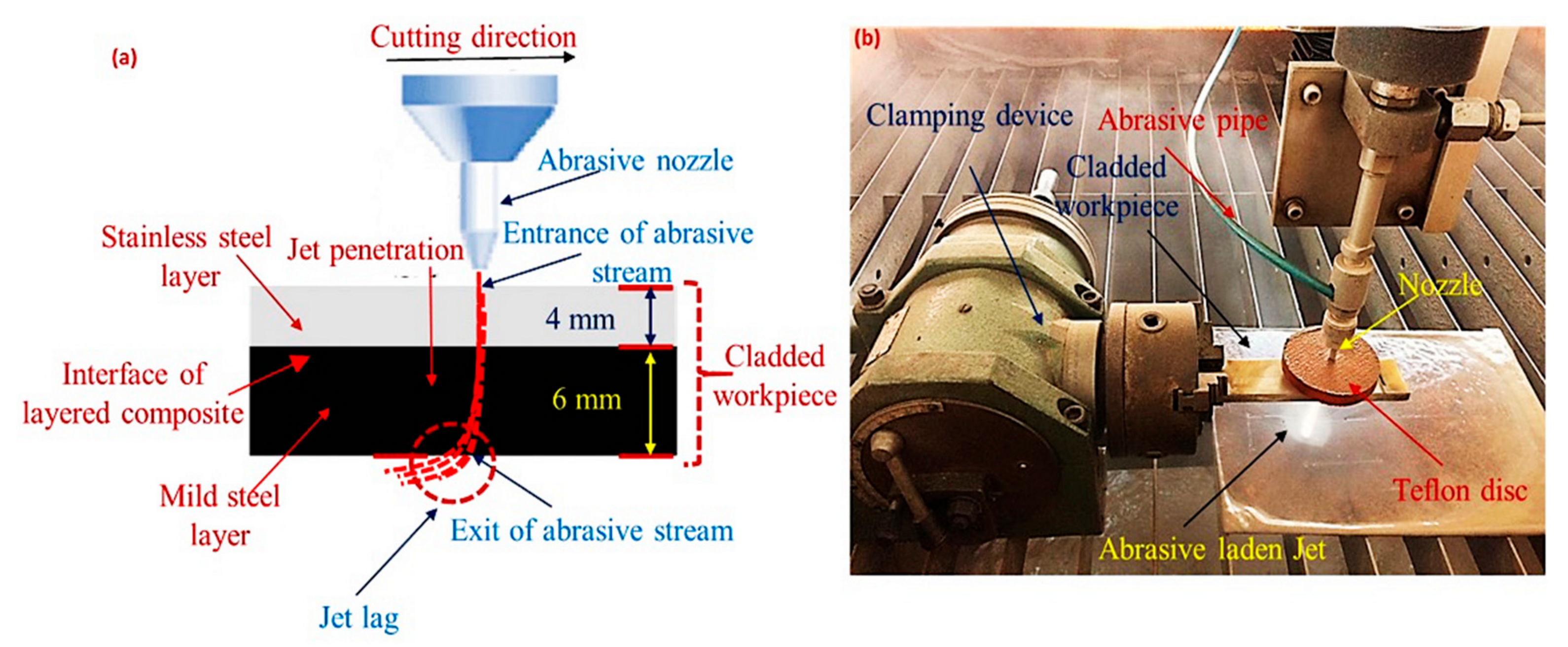
Abrasive water jet cutting (AWJC) could be a valuable substitute for the machining of cladded materials as it has relatively less drawbacks with respect to the damage of the workpart. Additionally, AWJC has no thermal effects and holds a high degree of flexibility with respect to cutting profiles. Above all, it is an environmentally friendly technique [10]. In AWJC, the stream of abrasive particles is mixed with the water jet in such a way that the jet momentum is partly transferred to the abrasive particles. The role of water medium is primarily to accelerate the abrasive particles and produces a highly coherent jet. This jet is targeted to the cutting area for performing machining action [11]. It is pertinent to mention that no work has been found, in open available literature, discussing the cutting of clad composite through abrasive water jet cutting. However, a part of the present study discussing the kerf taper and material removal issues during the AWJC of clad composite can has been recently published [12]. This in turns justifies the novelty of the work as the cutting performance of AWJC has not been reported for the machining of clad composite.
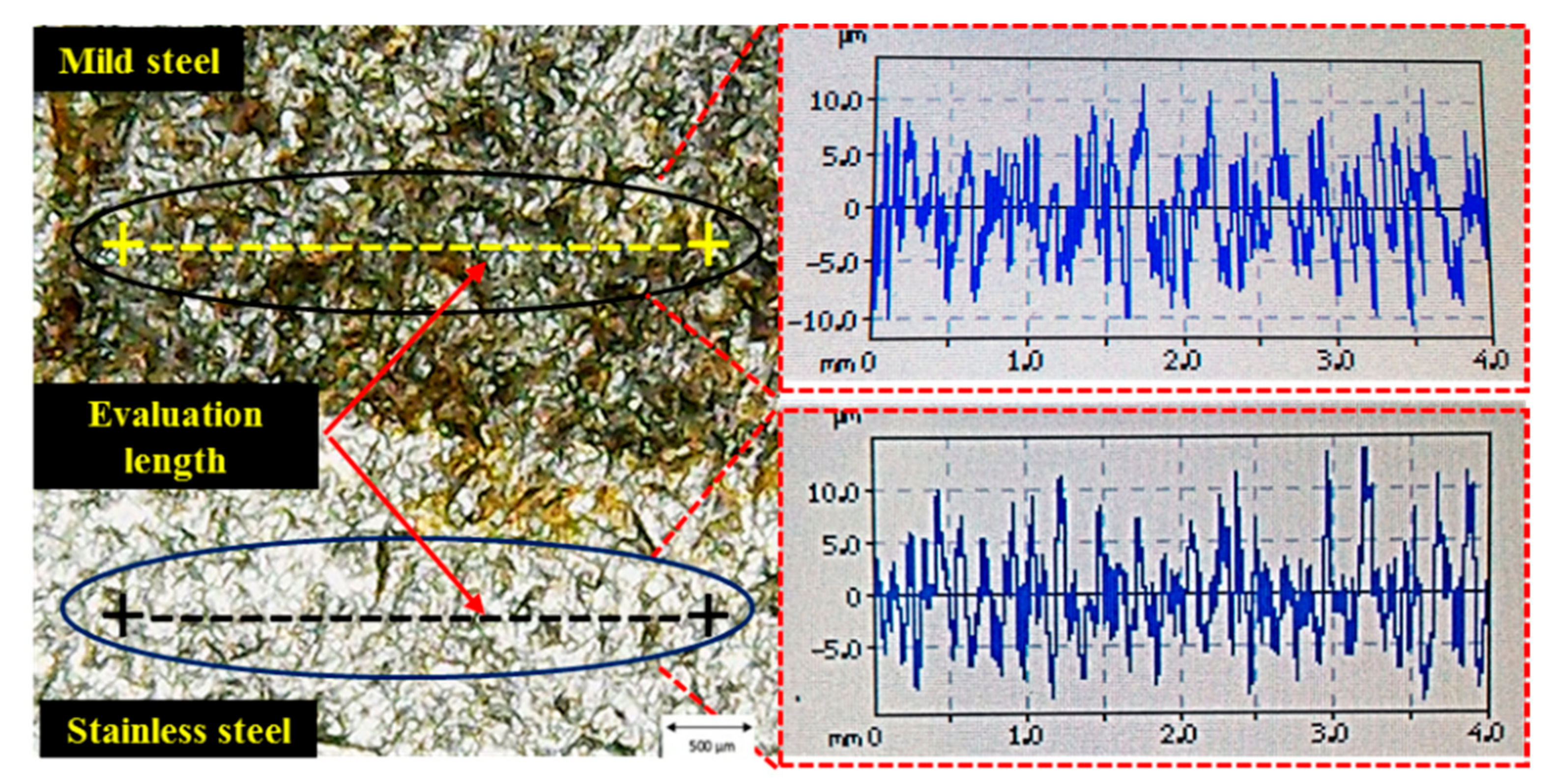
Keeping in view the prior benefits associated with the use of AWJC, the present study examines its potential for machining clad composite specimen in terms of surface finish. The rationale for selecting the surface finish as a response is its dominant importance in governing the final quality of the machined specimen [13]. Several properties like corrosion, wear and fatigue resistance are mainly governed by the level of surface finish [14]. Therefore, surface roughness (Ra) has been selected as the response characteristic.
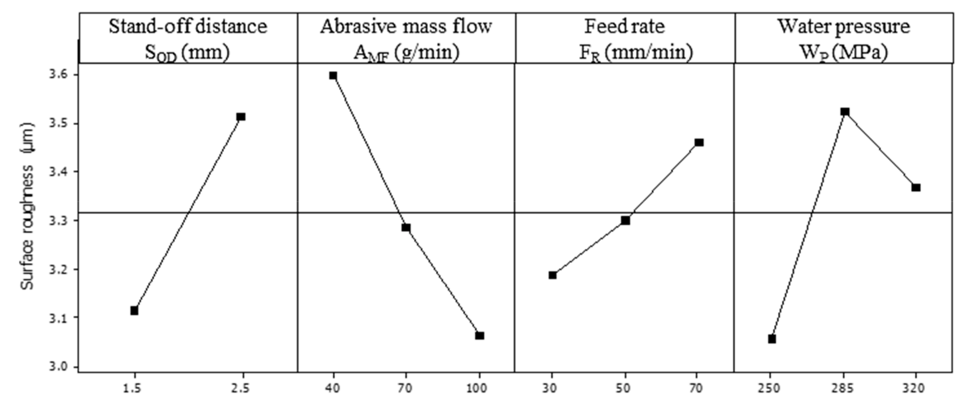
Considerable research has been conducted in the past to understand the mechanism and to investigate the parametric effects in AWJM with respect to surface roughness. For instance, Babu et al. [15] have found that water pressure (WP) is the most contributing factor for Ra during AWJM of brass-360. Uthayakumar et al. [16] also reported that WP was the prominent factor affecting the surface morphology of Ni-based super alloy cut by abrasive water jet. In another piece of research, it was concluded that the surface roughness decreased as the WP and abrasive mass flow (AMF) increased. Contrarily, a reverse trend is observed for the stand-off distance (SOD), traverse speed (FR) and abrasive grain size during the AWJM of ceramics tiles [17]. The cutting capability of AWJM for the cutting of gemstones can be seen in [18]. It was reported that the feed rate (FR) and depth distance of jet were the two influential factors for the Ra of cut specimens of gemstones. Karakurt et al. [19] evaluated the impact of five input parameters, namely: feed rate; FR, standoff distance; SOD, abrasive grain size, water pressure; WP and abrasive mass flow; AMF on kerf width during the machining of granitic rocks. It was found that traverse speed and standoff distance were the two contributing factors for kerf width. A multivariable regression model was also developed and validated. Selvan et al. [20] investigated the effect of WP, SOD, FR and AMF for the cutting of cast iron. Jagadish et al. [21] developed the optimal parametric settings of three abrasive water jet input factors, namely: water pressure, standoff distance and nozzle speed, for the machining of green composite using response surface methodology. Results revealed that the surface roughness was found to be minimum at a water pressure of 150 Mpa, standoff distance of 3.5 mm and 125 mm/min nozzle speed. Yuvaraj et al. [22] carried out multi-objective optimization using Technique for Order Preference by Similarity Ideal Solution (TOPSIS) approach during abrasive water jet machining of aluminum alloy (AA5083-H32). Five responses namely: penetration depth, cutting speed, kerf taper, top kerf width and Ra were simultaneously optimized using TOPSIS technique. A water pressure of 300 MPa, traverse rate of 120 mm/min, standoff distance of 1 mm and AMF of 360 g/min were the optimal settings.
The potential of the AWJC had been tested for a variety of materials, but its cutting capability for the machining of clad composites, specifically for stainless-clad steel, had not been thoroughly examined so far. The real challenge regarding the use of this cutting technique is to control the surface finish at both of the layers of composite. An adequate level of surface finish in both the layers is not the only requirement; it is also essential that both the layers hold a similar surface finish level, as this material must be used in composite form in its end application. This aspect, with regard to the AWJC of layered composite, has not been explicitly studied yet. Therefore, in the present research cutting performance is comprehensively investigated for the cutting of layered materials with an emphasis on minimizing the surface roughness of the individual layer. Moreover, the difference between the surface roughness values of both the layers is also minimized. The optimization of the process parameters is commonly recommended to eliminate the wastage of resources, especially materials and energy [23]. Signal to noise ratio is one of the commonly used approaches to optimize the process parameters [24]. Therefore, weighted signal-to-noise ratio method, a multi-objective optimization approach, is applied to develop an optimal parametric setting that can provide minimum surface roughness of each layer having a minimal difference from the neighboring layer.

2. Materials and Methods

This research is oriented in evaluating the cutting capability of AWJM for stainless-clad steel. This material has been used in a variety of different applications, such as boiler tubing, heat exchangers, etc. The selected workpiece is made up of two layers. One layer is of stainless steel (SSL) while the other is of Mild steel (MSL). Both of these layers are joined together by the process of weld overlay to produce the cladded specimen. The chemical composition of selected workpiece material has been validated via optical emission spectrometry using a standard method ASTM E 1676-4. The chemical composition of the selected material is provided in Table 1. Salient properties of stainless-clad steel like density, yield strength, percentage elongation etc. are extracted from literature and are tabulated in Table 2. The thickness of the specimen used for experimentation was 10 mm, out of which 4 mm is of SSL whereas the rest of the thickness is of mild steel. The workpiece is clamped into a clamping device and the flatness of the work surface is ensured with the aid of sprit level. The abrasive nozzle is set at an angle of 90° to ensure the orthogonal cutting. A garnet abrasive of 80 mesh size was employed for the cutting of clad composite in a single pass. The schematic of cutting and actual setup used for experimentation is described in Figure 1.
The cutting performance of AWJC for machining clad composite is assessed in terms of surface roughness. During each experimental run, a 40 mm cut-length was machined on an abrasive water jet machine (model: WC3WB1212H). Upon the completion of each experiment, the surface roughness was measured for both of the layers of clad composite using surface texture meter (model: Surtronic S128). An evaluation length of 4 mm and a cut-off length of 0.8 mm was used for roughness measurement. For each layer, three readings of roughness were taken, and then the average value was reported. The measurement procedure adopted for taking the measurements of surface roughness at both the layers has been elaborated in Figure 2. The value of roughness has been taken for both the layers, i.e., stainless steel (Ra(SS)) and mild steel (Ra(MS)). Four key parameters were considered as the input variables namely; stand-off distance (SOD), abrasive mass flow (AMF), feed rate (FR) and water pressure (WP). The selection of these parameters was based on the rationale that their impact has been noted as significant on surface roughness in the reported literature [15,16,17,18,20]. Preliminary trials were also performed for selecting the appropriate levels of the selected control variables. Striation formation and jet deflection, the two problematic issues associated with the AWJC, have been given due consideration during preliminary trials. The selection of the levels is done in such a way that the chances of striation formation and jet deflection would be minimal. It has also been ensured that abrasive laden jet can produce a through cut in a single pass. All the parameters have three levels, except the stand-off distance that has two levels. It was noted during the preliminary experimentation that if the value of SOD was reduced below 1 mm, the retraction of the abrasive grains damages the abrasive nozzle. On the other end, if the value of SOD is raised beyond 2.5 mm, the value of the effective width of the jet is enlarged before the interaction with the target surface. As a result, the kinetic energy of the abrasive laden jet has been reduced and it cannot produce a through cut. It is important to mention that the workpiece placement is also a critical consideration in this study as material comprises of two layers and both have different mechanical properties. The workpiece was placed in such a manner that SSL lies at the top, whereas MSL faces the bottom. The rationale for selecting this work orientation is to take advantage of abrasive particles’ kinetic energy because SSL (55 HRA) is harder compared to MSL (48 HRA). In fact, at the start of the cut, the abrasive laden jet has more penetration power owing to its higher kinetic energy. The magnitude of this energy reduces as the jet moves downward because this energy is consistently consumed in cutting the material. Therefore, it is advantageous to place SSL at the top so that the harder layer can be machined due to the higher kinetic energy of the abrasive jet. Though the abrasive jet consumes its energy to cut the upper layer, the lower layer of the material is softer, hence it can also be machined. Parameters and their levels are tabulated in Table 3. The rest of the control variables were treated as constant factors.
Experimentation has been planned according to the robust Taguchi experimental design technique. This experimental methodology provides an opportunity to have accurate experimental results with a fewer number of experiments. In a similar practice, several studies can be found using Taguchi L18 for having a low number of experimental runs to control the time and cost of experimentation [25,26,27]. The optimized setting proposed via Taguchi design makes the process so robust that it can minimize the impact of noise factors on the process output. In this experimental technique the number of experiments is governed by the number of control variables and their level values. In the present work there are four control variables, each having three levels, except stand-off distance which has two levels. Therefore, a mixed level design array is selected. According to the number of control variables and their levels taken in this work, the L18 orthogonal array was found suitable for performing the experimentation. The experimental results have been thoroughly analyzed using various statistical techniques. Optical and scanning electron microscopic (SEM) images of the machined surface have also been taken for an in-depth evaluation of the parametric effects. Finally, the optimal parametric combination has been developed using a weighted signal-to-noise ratio method that ensures minimal surface roughness of each layer with a minute difference. This technique consists of five steps which are described below:
  • Calculation of S/N ratio for each response variable;
  • Calculation of scaled signal-to-noise (SSN ratio) for each response;
  • Assign weights to scaled signal-to-noise ratio of each response and find weighted signal-to-noise ratio of output variables;
  • Find the level averages for the weighted S/N ratios;
  • Identify the optimal parametric level combination that can simultaneously optimize all the response attributes.
As a first step, the value of S/N ratio has been calculated for the selected response using the relation described in Equation (1). S/N ratio was calculated for surface roughness of both layers (SSL & MSL) using the same relationship.
η i j = 10 log ( 1 n k = 1 n Y i j 2 )
where, η accounts for S/N ratio and Yij is representing experimental value of jth response in ith trial. After that, the SSN ratio has been found using the Equation (2).
SSN = [ η η ( min ) ] / [ η ( max ) η ( min ) ]
Here, SSN = scaled signal-to-noise ratio, η(max) = maximum value of η from entire data, η(min) = minimum value of η from entire data
In the third step, weighted S/N ratio has been found for Ra of both layers using the relation mentioned in Equation (3).
WSN = ( P × SSN )
where, P = weightage given to each output response
In this work, equal weights are assigned to all the objectives. There is an involvement of three responses in this study; surface roughness of stainless steel layer (Ra(SS)), roughness of mild steel layer (Ra(MS)) and the difference of roughness value between the two constituent layers (δ). The roughness difference between the two layers is designated as delta (δ). Keeping in view that three responses are involved in the present work and all are equally important, a weightage of 0.33 has been assigned to all the responses. In the last step, level averages have been calculated based on the WSN ratios of all the experimental runs, and finally the optimal combination has been established.

3. Results

Experimentation on layered composite has been successfully performed under DOE (L18). In each experimental run a cut length of 40 mm was produced. Afterwards, the surface roughness of all the samples was measured in terms of arithmetic average which is a commonly used parameter in the industry for assessing the surface finish of the machined part. As the machined sample is composed of two layers of material, the surface roughness of both the layers has been measured. The results of experimentation have been tabulated in Table 4. Experimental results obtained after experimentation and measurement are thoroughly analyzed using statistical and SEM analyses.

3.1. Parametric Significance Analysis

Analysis of variance has been carried out for examining the parametric significance with respect to the selected responses. A confidence interval of 95% has been defined as a criterion for rating a parametric effect as significant. According to this criterion, any control variable having a p-value less than 0.05 would be considered as significant for the selected output variable. It is evident from the results of ANOVA presented in Table 5, that SOD, AMF, and WP are the significant control factors for the surface roughness of the stainless-steel layer (SSL). Whereas, the roughness of the mild steel layer (MSL) is primarily influenced by AMF and FR as described in Table 6. The percentage contribution of control variables for both the surfaces has also been calculated as shown in Figure 3. It has been found that the percentage contribution of input parameters namely; SOD, AMF, FR and WP for controlling the surface roughness of SSL is 25%, 31%, 8%, and 24%, respectively. Whereas, in case of MSL surface roughness, AMF holds the leadingly high percentage contribution of 68.3% followed by FR which has a percentage contribution of 19%.
It is pertinent to mention that percentage contribution of control variables is different for both the layers despite the fact that the layered composite is subjected to cut via AWJM in a single pass. Moreover, the surface texture produced on both layers of material is different as highlighted in Figure 4. The heterogeneous nature of the composite is mainly responsible for this shift. It is worth-noting that AMF has proven to be the most contributing parameter for both the layers (SSL and MSL). However, the percentage contribution of AMF for controlling surface roughness of MSL is approximately double compared to its percentage contribution towards SSL surface roughness. The surfaces finish of SSL is mainly dependent on SOD, AMF and WP, however the surface finish of MSL is predominantly controlled by AMF and FR. This shift of parametric significance happens because as the jet stream penetrates down the thickness of work surface, its kinetic energy has been reduced. This dropped magnitude of the kinetic energy has been utilized in mechanical shearing of the substrate material. Subsequently, jet dynamics observed at exit is different to that found at the jet entry. Hence, both the layers of bi-metal clad experience different magnitude of mechanical shear resulting into dissimilar surface qualities. Therefore, it is challenging to have a similar surface finish on both the layers. This requires finding an optimal parametric combination that not only provides minimum surface roughness of both the layers, but also minimizes the difference to offer a similar kind of cut quality.

3.2. Parametric Effects Analysis

After evaluating the parametric significance through ANOVA, the main effects plot analysis has been carried out to perceive the trend of control variables for the selected response characteristics. The results of the aforesaid analysis have been shown in Figure 5 and Figure 6. It has been noticed that the control variables portray the similar trends for the surface roughness of SSL and MSL despite their difference in percentage contribution. The accompanying discussion on the parametric trends is described in the up-coming sections.

3.2.1. Effect of SOD on Surface Quality

As mentioned earlier, SOD has proven to be a significant control variable for the surface roughness of SSL and statistically insignificant for the MSL surface finish according to the ANOVA results. The same has also been witnessed from the parametric effects plots described in Figure 5 and Figure 6. The reduction in the magnitude of kinetic energy is primarily responsible for this trend as abrasive laden stream has already consumed its energy while penetrating down the workpiece. That was also the reason for placing the SSL at the top to take the advantage of this kinetic energy considering that SSL is harder compared to MSL. It has been observed that SOD demonstrates a linear relationship with respect to surface roughness, i.e., an increase in the value of SOD results into the larger value of Ra. A similar trend has been reported in [28]. This relationship holds true for the surface roughness of both the layers (SSL & MSL) of clad composite. With the increase in SOD, the distance between the abrasive jet nozzle and the target workpiece is increased which helps to raise the momentum of abrasive grains. This increase in the momentum improves the penetration power of the abrasive grain. Thus, a deeper crater is formed at the target surface. Consequently, a poor surface finish is obtained as depicted in Figure 7.

3.2.2. Effect of AMF on Surface Quality

The effect of AMF on surface finish is the opposite to that of SOD, i.e., a larger value of the said control variable results into smaller surface roughness. The trend of AMF is observed alike for both the SSL and MSL layers. It is worth-noting that AMF has proven to be the major contributing parameter for the surface finish of both the layers. However, its contribution is more prominent for Ra(MS) in contrast to Ra(SS) as depicted in Figure 3. The same has also been observed in the parametric effect plots described in Figure 5 and Figure 6. At the larger value of AMF (100 g/min), a small magnitude of surface roughness of both the layers has been obtained. The main reason behind the trend of AMF is the change in the mode of shearing action associated with the change in value of AMF. In AWJM, cutting action has been accomplished by the abrasive laden slurry. The abrasive grains impart an impact load on the target surface that causes shearing of the work surface. As the magnitude of AMF is raised from lower to higher value, a greater number of abrasive grains are available for performing the cutting action in the machining regime. In other words, more cutting sites are available in the cutting area to mechanically shear-off the workpiece material. This increase in the number of shear sites has promoted the uniform erosion of the material from the target surface. This uniformity in cutting action yields lesser surface irregularities. Hence, the surface finish of the machined surface has been improved. The same has also been witnessed by the authors of [8] during AWJC of Carbon Fiber Reinforced Plastic (CFRP) and aluminum alloy UNS A97050 stack. This phenomenon is also visible in scanning electron microscope (SEM) images shown in Figure 8 and Figure 9. Quality of SSL and MSL machined surfaces at 40 and 100 g/min of AMF has been examined in these micrographs. It has been noted that surfaces of both the stainless steel as well as of the mild steel are found relatively smoother (smaller surface roughness) at larger AMF. At smaller AMF, shear marks found at the machined surface demonstrate that material has been removed in a non-uniform manner from both the layers as mentioned in Figure 8a and Figure 9a. On the other end, SEM images recorded at larger AMF depicts that shearing occurs in a relatively more uniform manner. Another important observation that has been evidenced in the SEM images is the embedment of abrasive particles of the machined surface. But this phenomenon is only observed on the surface of MSL. This is mainly attributed to the lower hardness of the MSL. Interestingly, the surface texture of both the layers has been noted to be appreciably different from each other even though both layers are machined in a single pass. This difference is prominently seen in Figure 8 and Figure 9.

3.2.3. Effect of FR on Surface Quality

Based on the parametric effects demonstrated in Figure 5 and Figure 6, it has been envisaged that lower FR has a positive impact on the surface finish of the clad specimen. At a higher value of FR, surface roughness of both the layers has been reduced. The main reason behind this trend is the contact time between the abrasive laden with the target surface. When the magnitude of FR is higher, abrasive laden traverses at a faster rate along the cut dimension which in turn reduces the contact time between the abrasive laden waterjet and the target surface. This reduction in the contact time upsurges the cutting rate during AWJC. However, this increase in the cutting rate is associated with a prominent drawback of generating non-uniform shearing of material from the target surface. Thus, non-uniform occurrence of shearing provides poor surface quality. The same has also been witnessed by the SEM micrograph shown in Figure 10. A similar trend of FR with respect to surface roughness has also been cited in another work [8].

3.2.4. Effect of WP on Surface Quality

The trend of WP with respect to the surface finish of both the layers has been described in Figure 5 and Figure 6. Experimental results revealed that the value of surface roughness is increased with the increase in WP from 250 MPa to 285 MPa. The reason behind this trend is the increase in the magnitude of kinetic energy of the abrasive jet with the rise of the value of WP. This increment in the kinetic energy of the jet accelerates the abrasive particles more energetically. When these accelerated abrasive particles encounter the target surface, they impart a greater amount of shear load during their collision due to having larger kinetic energy. Consequently, deeper crates are formed at the machined surface which promotes the surface roughness. The same has also been validated in the SEM micrographs of the machined area presented in Figure 11. At larger WP (285 MPa) deeper craters are formed, while at lower WP (250 MPa) shallow craters are produced. Owing to the decrease in the craters’ depth the surface finish is improved as highlighted in Figure 11. However, an increased trend has been observed for the surface roughness of both the layers with the rise in WP from 250 MPa to 285 MPa. However, this impact is statistically significant for SSL only as mentioned in Table 5 and Table 6. This is because the abrasive jet loses its kinetic energy as it moves down along the workpiece thickness. The kinetic energy of the abrasive laden jet is successively dissipated due to its collisions with the work surface. This is why the change in water pressure is unable to produce a noticeable change in the surface roughness of MSL as the jet’s kinetic energy has already been dissipated by the upper layer of stainless steel (having higher hardness of 55 HRA). Therefore, the effect of change of WP turns out to be insignificant. It is interesting to note that the surface roughness of both the SSL and the MSL layers was reduced as the value of WP rose from 285 MPa to 320 MPa. This was attributed to the reason that at a higher WP the shear load on the abrasive grains is increased. Bouad et al. [29] claimed that if the shear load experienced by the abrasive grain is more than its crushing load, the abrasive particle gets fractured. The cutting capability of the crushed particles is reduced, and thus shallow craters are formed. Subsequently, the magnitude of the surface roughness is reduced.

3.3. Multi-Response Optimization

Optimal parametric combination has been identified in this section after comprehensively discussing the parametric effects and their relative significance for the surface roughness of each layer of clad composite. The development of the optimal setting is challenging because a smaller Ra value at each layer is not the only objective, but it is also required that the difference between the constituent layers’ roughness should also be minimal. Because this clad composite has to be employed as a single material in its end applications, therefore multi-response optimization (MRO) has been carried out in this research to achieve the said objective. A variety of multi-response optimization techniques are available like Vikor, Multi-response signal-to-noise (MSN), Weighted signal-to-noise (WSN) and Grey relational etc. however, WSN has proven to be most effective [30]. That is why in the present study WSN methodology is adopted. This methodology helps to identify those levels of control parameters that can provide the desired outcome of all the selected responses. The optimal combination iterated via said optimization method can be within the experimental design table or might be some other combination based on the selected parametric levels that is not a part of the design table. The steps associated with this optimization technique have already been discussed in the materials and methods section. As there are three responses which are under consideration in this research and it is desired to have their magnitude at the minimum level, equal weights have been assigned to each response characteristic. The results of weighted signal-to-noise ratio analysis are tabulated in Table 7 and Table 8.

3.3.1. Confirmatory Test

A confirmatory experiment has been performed after finding the optimal parametric combination through WSN to authenticate the developed optimal settings. The results of the experiment are tabulated in Table 9. It has been revealed that the optimal parametric combination provides a reduction of 34% in SSL surface roughness and 11% in MSL surface roughness. Moreover, the difference between the roughness values of the constituent layers is also observed to be quite small of just 0.03 µm magnitude. These results have also been validated from the roughness profiles recorded for the samples machined at the optimal and non-optimal parametric settings, as shown in Figure 12. At the non-optimal parametric settings of control variables larger surface irregularities are prominent at both the surfaces. On the other end, surface irregularities at both the layers and their respective difference is found reasonably small as highlighted in Figure 12.
It is pertinent to mention that the present study would be quite useful for the industries dealing with the cutting of cladded materials. Issues such as poor cut quality and deeper heat affected zones pertaining to the conventional thermal cutting processes can be eliminated through the use of AWJC. Furthermore, the requirement of subsequent finishing process has also been eradicated. The proposed optimal combination developed herein would be guaranteed to provide minimal surface roughness at each layer with a minute difference of just 0.03 µm in surface roughness. This work will hopefully open new horizons of the application and cutting of cladded materials.

4. Conclusions

Clad composites have emerged as a suitable choice to augment the industrial needs, but its accurate cutting is challenging because of heterogeneous properties of the constituent layers. Abrasive water jet cutting (AWJC) is a proficient alternate but it is difficult to produce a similar level of surface finish at both the layers of material in addition to minimizing the roughness of individual layer. Therefore, the present study aims to investigate the cutting performance of AWJC for cutting of clad composite with a dedicated focus on analyzing the surface quality of the machined surfaces. Experimentation has been performed according to L18 orthogonal array. The results are thoroughly examined using statistical and SEM analyses. The following conclusion may possibly be extracted based on the experimental findings and their discussion:
  • Clad composite can be successfully machined using AWJC with adequate surface quality. However, the parametric significance for roughness of both the constituent layers is found to be different.
  • Roughness of stainless-steel layer (SSL) is primarily influenced by AMF, SOD and WP. Whereas in case of mild steel layer (MSL) surface roughness, only two control variables i.e., AMF and FR are found significant.
    AMF has been observed to be the most contributing variable for both the SSL and MSL. However, its contribution for MSL roughness (68.3%) is more than two-fold its contribution for roughness of SSL (31%). Moreover, a larger magnitude of AMF yields better surface finish at both the layers because of the occurrence of uniform shearing action.
    SEM analysis depicts that few abrasive particles have been imbedded on the surface of MSL due to the lower hardness of MSL. This particle embedment is not observed at the surface of SSL.
    Smaller SOD provides better surface finish, but this effect is more prominent for stainless steel layer (SSL) as abrasive laden jet has consumed its energy while moving down the workpiece thickness.
    The effect of FR is found to have a direct relationship with the surface roughness of clad composite in AWJC. Higher value of FR results in inferior surface quality because inappropriate shearing action takes place due to shorter contact time between abrasive laden slurry with the target material. However, this effect is only significant for the lower layer (MSL) of clad composite.
    Increase in the magnitude of WP from 250 MPa to 285 MPa increases the roughness of both the SSL and MSL because at higher WP abrasive particles have larger kinetic energy and produce deeper craters upon striking the work surface. However, a further increase in WP results in a reduction of surface roughness.
  • Optimal settings of control variables are developed using WSN methodology which ensures that not only roughness of both the constituent layers is smaller, but the roughness difference is just of 0.03 µm. Furthermore, an improvement of 34% in the stainless steel layer’s surface roughness and 11% in mild steel surface roughness has also been realized using the developed optimal parametric combination.

Author Contributions

Conceptualization, K.I. and N.A.; Data curation, N.A.M. and M.Q.S..; Formal analysis, K.I.; Funding acquisition, A.M.A.-A.; Investigation, N.A. and K.I.; Methodology, K.I. and N.A.; Resources, A.M.A.-A., and N.A.M..; Supervision, K.I. and A.M.A.-A.; Validation, N.A. and M.Q.S..; Visualization, N.A.M. and K.I.; Writing—original draft preparation, K.I. and N.A.; Writing—review and editing, K.I., A.M.A.-A. and N.A..; Proofread—review and editing tables and figures, M.Q.S. and N.A.M.

Funding

Raytheon Chair for Systems Engineering, King Saud University, Saudi Arabia.

Acknowledgments

The authors are grateful to the Raytheon Chair for Systems Engineering for funding.

Conflicts of Interest

The authors declare no conflict of interest.

References

  1. Liu, B.X.; Yin, F.X.; Dai, X.L.; He, J.N.; Fang, W.; Chen, C.X.; Dong, Y.C. The tensile behaviors and fracture characteristics of stainless steel clad plates with different interfacial status. Mater. Sci. Eng. A 2017, 679, 172–182. [Google Scholar] [CrossRef]
  2. Sreeraj, P.; Kannan, T. Modelling and prediction of stainless steel clad bead geometry deposited by GMAW using regression and artificial neural network models. Adv. Mech. Eng. 2012, 4, 237379. [Google Scholar] [CrossRef]
  3. Ur Rahman, N.; de Rooij, M.B.; Matthews, D.T.A.; Walmag, G.; Sinnaeve, M.; Römer, G.R.B.E. Wear characterization of multilayer laser cladded high speed steels. Tribol. Int. 2019, 130, 52–62. [Google Scholar] [CrossRef]
  4. Cui, G.; Han, B.; Zhao, J.; Li, M. Comparative study on tribological properties of the sulfurizing layers on Fe, Ni and Co based laser cladding coatings. Tribol. Int. 2019, 134, 36–49. [Google Scholar] [CrossRef]
  5. Feng, Z.-C.; Liu, Y.-F.; Li, Y.; Sun, G.-B.; Zhang, Z.; Shi, C.-X. Microstructure and high temperature reciprocating sliding wear properties of MoSi2/TiC/γ-Ni composite coating in-situ synthesized by co-axial powder feeding plasma transferred arc cladding. Tribol. Int. 2019, 129, 82–91. [Google Scholar] [CrossRef]
  6. Yu, Y.; Zhou, J.; Ren, S.; Wang, L.; Xin, B.; Cao, S. Tribological properties of laser cladding NiAl intermetallic compound coatings at elevated temperatures. Tribol. Int. 2016, 104, 321–327. [Google Scholar] [CrossRef]
  7. Nieslony, P.; Cichosz, P.; Krolczyk, G.M.; Legutko, S.; Smyczek, D.; Kolodziej, M. Experimental studies of the cutting force and surface morphology of explosively clad Ti-steel plates. Meas. J. Int. Meas. Confed. 2016, 78, 129–137. [Google Scholar] [CrossRef]
  8. Ruiz-Garcia, R.; Mayuet Ares, P.F.; Vazquez-Martinez, J.M.; Salguero Gómez, J. Influence of abrasive waterjet parameters on the cutting and drilling of CFRP/UNS A97075 and UNS A97075/CFRP stacks. Materials 2018, 12, 107. [Google Scholar] [CrossRef]
  9. Ishfaq, K.; Mufti, N.A.; Ahmed, N.; Mughal, M.P.; Saleem, M.Q. An investigation of surface roughness and parametric optimization during wire electric discharge machining of cladded material. Int. J. Adv. Manuf. Technol. 2018, 97, 4065–4079. [Google Scholar] [CrossRef]
  10. Azmir, M.A.; Ahsan, A.K. A study of abrasive water jet machining process on glass/epoxy composite laminate. J. Mater. Process. Technol. 2009, 209, 6168–6173. [Google Scholar] [CrossRef]
  11. Momber, A.W.; Wong, Y.C.; Ij, R.; Budidharma, E. Hydrodynamic profiling and grit blasting of low-carbon steel surfaces. Tribol. Int. 2002, 35, 271–281. [Google Scholar] [CrossRef]
  12. Ishfaq, K.; Mufti, N.A.; Ahmed, N.; Pervaiz, S. Abrasive waterjet cutting of cladded material: kerf taper and MRR analysis. Mater. Manuf. Process. 2019, 34, 544–553. [Google Scholar] [CrossRef]
  13. Tosun, N.; Cogun, C.; Inan, A. The effect of cutting parameters on workpiece surface roughness in wire EDM. Mach. Sci. Technol. 2003, 7, 209–219. [Google Scholar] [CrossRef]
  14. López, J.G.; Verleysen, P.; Degrieck, J. Effect of fatigue damage on static and dynamic tensile behaviour of electro-discharge machined Ti-6Al-4V. Fatigue Fract. Eng. Mater. Struct. 2012, 35, 1120–1132. [Google Scholar] [CrossRef]
  15. Yue, Z.; Huang, C.; Zhu, H.; Wang, J.; Yao, P.; Liu, Z. Optimization of machining parameters in the abrasive waterjet turning of alumina ceramic based on the response surface methodology. Int. J. Adv. Manuf. Technol. 2014, 71, 2107–2114. [Google Scholar] [CrossRef]
  16. Uthayakumar, M.; Khan, M.A.; Kumaran, S.T.; Slota, A.; Zajac, J. Machinability of nickel-based superalloy by abrasive water jet machining. Mater. Manuf. Process. 2016, 31, 1733–1739. [Google Scholar] [CrossRef]
  17. Santhanakumar, M.; Adalarasan, R.; Rajmohan, M. Experimental modelling and analysis in abrasive waterjet cutting of ceramic tiles using grey-based response surface methodology. Arab. J. Sci. Eng. 2015, 49, 3299–3311. [Google Scholar] [CrossRef]
  18. De Abreu E Lima, C.E.; Lebrón, R.; de Souza, A.J.; Ferreira, N.F.; Neis, P.D. Study of influence of traverse speed and abrasive mass flowrate in abrasive water jet machining of gemstones. Int. J. Adv. Manuf. Technol. 2016, 83, 77–87. [Google Scholar] [CrossRef]
  19. Karakurt, I.; Aydin, G.; Aydiner, K. An investigation on the kerf width in abrasive waterjet cutting of granitic rocks. Arab. J. Geosci. 2014, 7, 2923–2932. [Google Scholar] [CrossRef]
  20. Selvan, C.P.; Raju, M.S. Analysis of surface roughness in abrasive waterjet cutting of cast iron. Int. J. Sci. Environ. Technol. 2012, 1, 174–182. [Google Scholar]
  21. Jagadish Bhowmik, S.; Ray, A. Prediction and optimization of process parameters of green composites in AWJM process using response surface methodology. Int. J. Adv. Manuf. Technol. 2016, 87, 1359–1370. [Google Scholar] [CrossRef]
  22. Yuvaraj, N.; Pradeep Kumar, M. Multiresponse optimization of abrasive water jet cutting process parameters using TOPSIS approach. Mater. Manuf. Process. 2015, 30, 882–889. [Google Scholar] [CrossRef]
  23. Mia, M.; Królczyk, G.; Maruda, R.; Wojciechowski, S. Intelligent optimization of hard-turning parameters using evolutionary algorithms for smart manufacturing. Materials 2019, 12, 879. [Google Scholar] [CrossRef] [PubMed]
  24. Wojciechowski, S.; Maruda, R.W.; Krolczyk, M.G.; Niesłony, P. Application of signal to noise ratio and grey relational analysis to minimize forces and vibrations during precise ball end milling. Precis. Eng. 2018, 51, 582–596. [Google Scholar] [CrossRef]
  25. Lin, Y.-C.; Wang, A.-C.; Wang, D.-A.; Chen, C.-C. Machining performance and optimizing machining parameters of Al2O3–TiC ceramics using EDM based on the Taguchi method. Mater. Manuf. Process. 2009, 24, 667–674. [Google Scholar] [CrossRef]
  26. Lin, Y.-C.; Cheng, C.-H.; Su, B.-L.; Hwang, L.-R. Machining characteristics and optimization of machining parameters of SKH 57 high-speed steel using electrical-discharge machining based on Taguchi method. Mater. Manuf. Process. 2006, 21, 922–929. [Google Scholar] [CrossRef]
  27. Babu, M.N.; Muthukrishnan, N. Investigation of multiple process parameters in abrasive water jet machining of tiles. J. Chin. Inst. Eng. 2015, 38, 692–700. [Google Scholar] [CrossRef]
  28. Babu, M.N.; Muthukrishnan, N. Investigation on surface roughness in abrasive water-jet machining by the response surface method. Mater. Manuf. Process. 2014, 29, 1422–1428. [Google Scholar] [CrossRef]
  29. Boud, F.; Carpenter, C.; Folkes, J.; Shipway, P.H. Abrasive waterjet cutting of a titanium alloy: The influence of abrasive morphology and mechanical properties on workpiece grit embedment and cut quality. J. Mater. Process. Technol. 2010, 210, 2197–2205. [Google Scholar] [CrossRef]
  30. Gauri, S.K.; Chakraborty, S. A study on the performance of some multi-response optimisation methods for WEDM processes. Int. J. Adv. Manuf. Technol. 2010, 49, 155–166. [Google Scholar] [CrossRef]
Figure 1. Experimental setup for AWJM of clad composite; (a) Schematic, and (b) Actual setup.
Metals 09 00754 g001
Figure 2. Measurement of roughness; (a) Actual measurement and (b) Schematic of measurement.
Metals 09 00754 g002
Figure 3. Parameter’s contribution (%) for both layers.
Metals 09 00754 g003
Figure 4. Surface texture comparison of SSL and MSL.
Metals 09 00754 g004
Figure 5. Parametric effect plots for Ra(SS).
Metals 09 00754 g005
Figure 6. Parametric effect plots for Ra(MS).
Metals 09 00754 g006
Figure 7. Optical micrographs of machined area at; (a) larger SOD = 2.5 mm, (b) smaller SOD = 1.5 mm.
Metals 09 00754 g007
Figure 8. SEM micrographs of SSL machined at; (a) AMF = 40g/min, (b) AMF = 100 g/min.
Metals 09 00754 g008
Figure 9. SEM micrographs of MSL machined at; (a) AMF = 40 g/min, (b) AMF = 100 g/min.
Metals 09 00754 g009
Figure 10. SEM micrograph of machined surface at 70 mm/min.
Metals 09 00754 g010
Figure 11. SEM micrographs of machined surface SSL; (a) At WP = 250 MPa, (b) At WP = 285 MPa.
Metals 09 00754 g011
Figure 12. Roughness profiles of SSL and MSL at; (a,b) non-optimal settings, (c,d) optimal settings.
Metals 09 00754 g012
Table 1. Workpiece chemical composition.
Stainless Steel LayerMild Steel Layer
Element(%)Element(%)
C0.08C0.17
Si0.83Si0.46
Mn0.92Mn1.13
P0.05P0.04
S0.013S0.01
Cr17.6--
Mo2.36--
Ni10.0--
FeBalanceFeBalance
Table 2. Workpiece material properties [9].
Physical/Thermal PropertiesStainless SteelMild SteelMechanical Properties
Density8.07 g/cc7.8 g/ccUltimate tensile strength595 MPa
Specific Heat0.5 J/g·°C0.47/g·°CPercentage Elongation14.8%
Thermal Conductivity17 W/m·K52.0W/m·KHardness of stainless-steel layer50 (HRA)
Coefficient of thermal expansion16 µm/m·°C12.0 µm/m·°CHardness of mild steel layer39 (HRA)
Table 3. Cutting parameters and their levels.
Control FactorsSymbolUnitsLevels
123
Abrasive mass flowAMFg/min4070100
Feed rateFRmm/min305070
Stand-off distanceSODmm1.52.5-
Water pressureWPMPa250285320
Table 4. Experimental results.
Sr. No.SOD (mm)AMF (g/min)FR (mm/min)WP (MPa)Ra(SS) (μm)Ra(SS) S/N Ratio (dB)Ra(MS) (μm)Ra(MS) S/N Ratio (dB)
11.540302503.28−10.31753.45−10.7564
21.570502853.26−10.26443.53−10.9555
31.5100703203.27−10.29103.13−9.9662
41.540302853.36−10.52683.49−10.8565
51.570503203.33−10.44893.64−11.2220
61.5100702502.54−8.19772.57−8.1987
71.540502502.99−9.51344.19−12.4443
81.570702853.41−10.65513.52−10.9309
91.5100303202.69−8.26602.56−8.1648
102.540703204.05−12.14914.24−12.4856
112.570302503.18−10.04852.89−9.2180
122.5100502853.47−10.80662.76−8.8182
132.540503203.69−11.34054.03−12.1061
142.570702503.25−10.23773.41−10.6551
152.5100302853.42−10.68052.84−9.0664
162.540702854.22−12.50624.71−13.4604
172.570303203.29−10.34392.85−9.0969
182.5100502503.17−9.74283.01−9.5713
Table 5. ANOVA for Ra(SS).
SourceDFSeq SSAdj SSAdj MSFPContribution (%)
SOD (mm)10.712020.712020.7120220.910.00125
AMF (g/min)20.861430.861430.4307212.650.00231
FR (mm/min)20.228900.228900.114453.360.0768
WP (MPa)20.678930.678930.339479.970.00424
Error100.340510.340510.03405--12
Total172.82180-----
Table 6. ANOVA for Ra(MS).
SourceDFSeq SSAdj SSAdj MSFPContribution (%)
SOD (mm)10.020670.020670.020670.320.5810.3
AMF (g/min)24.354234.354232.1771234.190.00068.3
FR (mm/min)21.213031.213030.606529.530.00519
WP (MPa)20.154630.154630.077321.210.3372.4
Error100.636680.636680.06367--10
Total176.37925-----
Table 7. Results of WSN calculation.
Sr No.Calculation of S/N RatioCalculation of SSN RatioCalculation of WSN
S/N Ra(SS)S/N Ra(MS)S/N (δ)SSN Ra(SS)SSN Ra(MS)SSN (δ)0.33(SSN Ra(SS)) + 0.33 (SSN Ra(MS)) + 0.33 (SSN δ)
1−10.3175−10.756415.3910.5081140.5106133.0401.324
2−10.2644−10.955511.3730.5204410.4730152.3201.094
3−10.2910−9.966218.4160.5142660.6598313.5821.569
4−10.5268−10.856517.7210.4595240.491713.4571.455
5−10.4489−11.222010.1730.4776090.4226912.1050.992
6−8.1987−8.198740.00010.9935987.4473.115
7−9.5134−12.4443−1.5840.6947880.1918760.0000.293
8−10.6551−10.930919.1720.4297390.4776613.7171.526
9−8.2660−8.164830.4580.98437615.7382.548
10−12.1491−12.485615.9180.0829020.1840773.1341.122
11−10.0485−9.218010.7520.5705630.8011182.2091.182
12−10.8066−8.81822.9750.3945680.8766150.8160.689
13−11.3405−12.10619.3700.2706210.2557411.9620.821
14−10.2377−10.655115.9180.526640.5297423.1341.383
15−10.6805−9.06644.7310.4238420.8297451.1310.787
16−12.5062−13.46046.196001.3930.460
17−10.3439−9.09697.1310.5019850.8239861.5610.953
18−9.7428−9.571324.4370.6415320.7344024.6601.992
Table 8. Results of level averages calculation.
Level 1Level 2Level 3Optimal LevelLevel ValueUnits
AMF0.9121.1881.7833100g/min
FR1.3750.9801.529370mm/min
WP1.5481.0021.3341250MPa
SOD1.6710.918-11.5mm
Table 9. Confirmatory experiment results.
Control Factors’ SettingLevelsRa(SS) (µm)Ra(MS) (µm)Difference (δ)
OptimalAMF 3, FR 3, WP 1, SOD 12.542.570.03
Non-optimalAMF 3, FR 1, WP 2, SOD 23.422.840.58
Improvement percentage34.6%11%

