Article

Comparative Study of Chip Formation in Orthogonal and Oblique Slow-Rate Machining of EN 16MnCr5 Steel

1
Faculty of manufacturing technologies with the seat in Presov, Technical University of Kosice, Sturova 31, 080 01 Presov, Slovakia
2
Faculty of Technology, UTB Tomas Bata University in Zlin, Vavreckova 275, 760 01 Zlin, Czech Republic
3
Faculty of Mechanical Engineering, VSB-Technical University of Ostrava, 17. listopadu 15/2172, 708 00 Ostrava-Poruba, Czech Republic
4
Faculty of Mechanical Engineering, West Bohemia University in Pilsen, Univerzitni 22, 301 00 Pilsen, Czech Republic
*
Author to whom correspondence should be addressed.
Metals 2019, 9(6), 698; https://doi.org/10.3390/met9060698
Submission received: 23 May 2019 / Revised: 15 June 2019 / Accepted: 18 June 2019 / Published: 20 June 2019
(This article belongs to the Special Issue Failure Mechanisms in Alloys)

Abstract

:
In today’s unmanned productions systems, it is very important that the manufacturing processes are carried out efficiently and smoothly. Therefore, controlling chip formation becomes an essential issue to be dealt with. It can be said that the material removal from a workpiece using machining is based on the degradation of material cohesion made in a controlled manner. The aim of the study was to understand the chip formation mechanisms that can, during uncontrolled processes, result in the formation and propagation of microcracks on the machined surface and, as such, cause failure of a component during its operation. This article addresses some aspects of chip formation in the orthogonal and oblique slow-rate machining of EN 16MnCr5 steel. In order to avoid chip root deformation and its thermal influence on sample acquisition, that could cause the changes in the microstructure of material, a new reliable method for sample acquisition has been developed in this research. The results of the experiments have been statistically processed. The obtained dependencies have uncovered how the cutting tool geometry and cutting conditions influence a chip shape, temperature in cutting area, or microhardness according to Vickers in the area of shear angle.

1. Introduction

Machining is a major manufacturing process in the engineering industry. The quality of a product is largely dependent on the accuracy and consistency of the machining processes used for the production of the parts. Although in the last few decades, some entirely new machining processes have been developed—such as ultrasonic machining, thermal metal removal processes, electrochemical material removal processes, and laser machining processes, which differ from the conventional machining processes—conventional metal cutting operations are still the most widely used fabrication processes, and this is the reason why it is still essential to develop a fundamental understanding of metal cutting processes.
In general, machining consists of both cutting and abrasive processes that are mostly complimentary. In spite of the fact that conventional metal cutting processes are chip-forming processes, chip control has been overlooked in the manufacturing processes for a long time. However, along with the automation of manufacturing processes, machining chip control becomes an essential issue in machining operations in order to carry out the manufacturing processes efficiently and smoothly, especially in today’s unmanned machining systems. It can be said that the material removal from a workpiece using machining is based on a degradation of material cohesion realized in a controlled way.
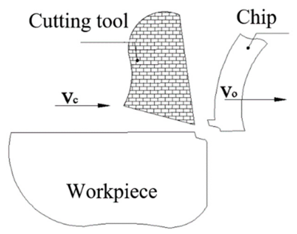
Chip removal produces technically and scientifically interesting material responses. In single point cutting, the process concentrates the mechanical power of a machine tool into creating the small volumes of the workpiece by forcing a hard-cutting tool with a small edge radius through an outer layer of the workpiece material. The tribological conditions at the tool–chip interface can result in macroscopic welding of the material to the cutting tool, and dissolution of the tool elements into the chip. The geometry of the deformation zones and the resulting microstructures in the workpiece depend on the geometrical and tribological interaction of the cutting tool with the workpiece material. Further understanding of fundamentals of chip formation is motivated by the desire for higher material removal rates, longer tool life, tighter tolerances, and improved quality of machined surfaces.
The goal of this article is to study some aspects of chip formation in the orthogonal and oblique slow-rate machining of EN 16MnCr5 steel. For the experimental comparative study, planing operation has been selected, by which the main sliding motion was performed by a workpiece. The main reason why this technology has been chosen is because chip formation is visible to the naked eye, in contrast to inward flanging (as another type of slow-rate machining), where the chip-forming process is hidden within the workpiece. For this reason, it has also been possible to measure the temperature in the cutting zone that is generated by the planing tool. The next factor was that restoring the cutting ability of the planing tools produced from high-speed steel by sharpening—according to the required parameters—was considerably easier when compared to turning tools.
Chip flow is only a part of chip space movement. To understand the chip formation mechanism, it is necessary to study other parameters that have an effect on the chip formation, and there are still many challenging issues to deal with.
Through the experimental measurements carried out in this study, different information has been gathered to help obtain a thorough understanding of the chip formation process at relatively low cutting speeds.

2. State of the Art

Chip machining is a complex process in which several mechanisms which are working simultaneously and interacting with each other. This process is greatly affected by material properties, cutting conditions, tool geometry, and machine tool dynamics. In any machining operation, the material is removed from the workpiece in the form of chips, the nature of which differs from operation to operation. As the form and dimensions of a chip from any process can reveal a lot of information about the nature and loyalty of process, the analysis of chips in the process of chip formation, by tear formation, is very important.
A lot of work has been conducted on chip flow angle research during the last few decades, and there are many methods for calculating of the chip flow angle. The investigation of chip flow began with modeling over plane rake face tools. Merchant [1] and Shaffer and Lee [2] have used plasticity theory to attempt to obtain a unique relationship between the chip shear plane angle, the tool rake angle, and the friction angle between the chip and the tool. Palmer [3] presented shear zone theory by allowing for variation in the flow stress for a work-hardening material. Von Turkovich [4] investigated the significance of work material properties and the cyclic nature of the chip formation process in metal cutting. Okushima [5] considered that chip flow is not influenced by cutting speed and chip flow should be the summation of elemental flow angles over the entire length of the cutting edge. Slip-line field theory is widely applied in chip formation research and some slip-line field models are presented [6,7,8]. Another chip flow model was presented by Young [9], assuming Stabler’s flow rule, with validity for infinitesimal chip width, and the directions of elemental friction forces summed up to obtain the direction of chip flow.
During machining, material is removed from the workpiece, where it flows out in the form of chips. After flowing out, the chip curls either naturally or through contact with obstacles. If the material strain exceeds the material breaking strain, the chip will break. Chip flow, chip curl, and chip breaking are three main areas of chip control research [10].
According to Toulfatzis et al. [
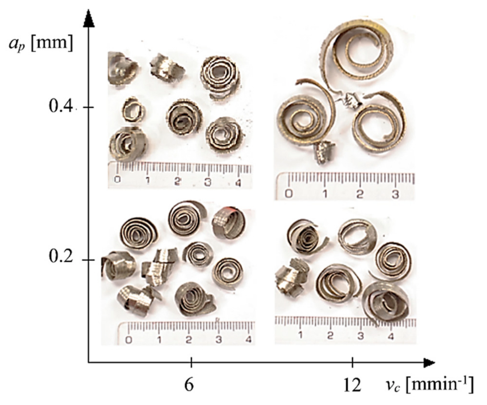
11], an improved chip breaking capability is directly connected with lower cutting tool wear rates. The width of the chips varies according to the different depths of cut employed during the various machining experiments. Chip segmentation is of pivotal importance since it facilitates the machining ergonomics and scrap removal without damaging workpiece surface quality and ensures the safety of the working personnel.
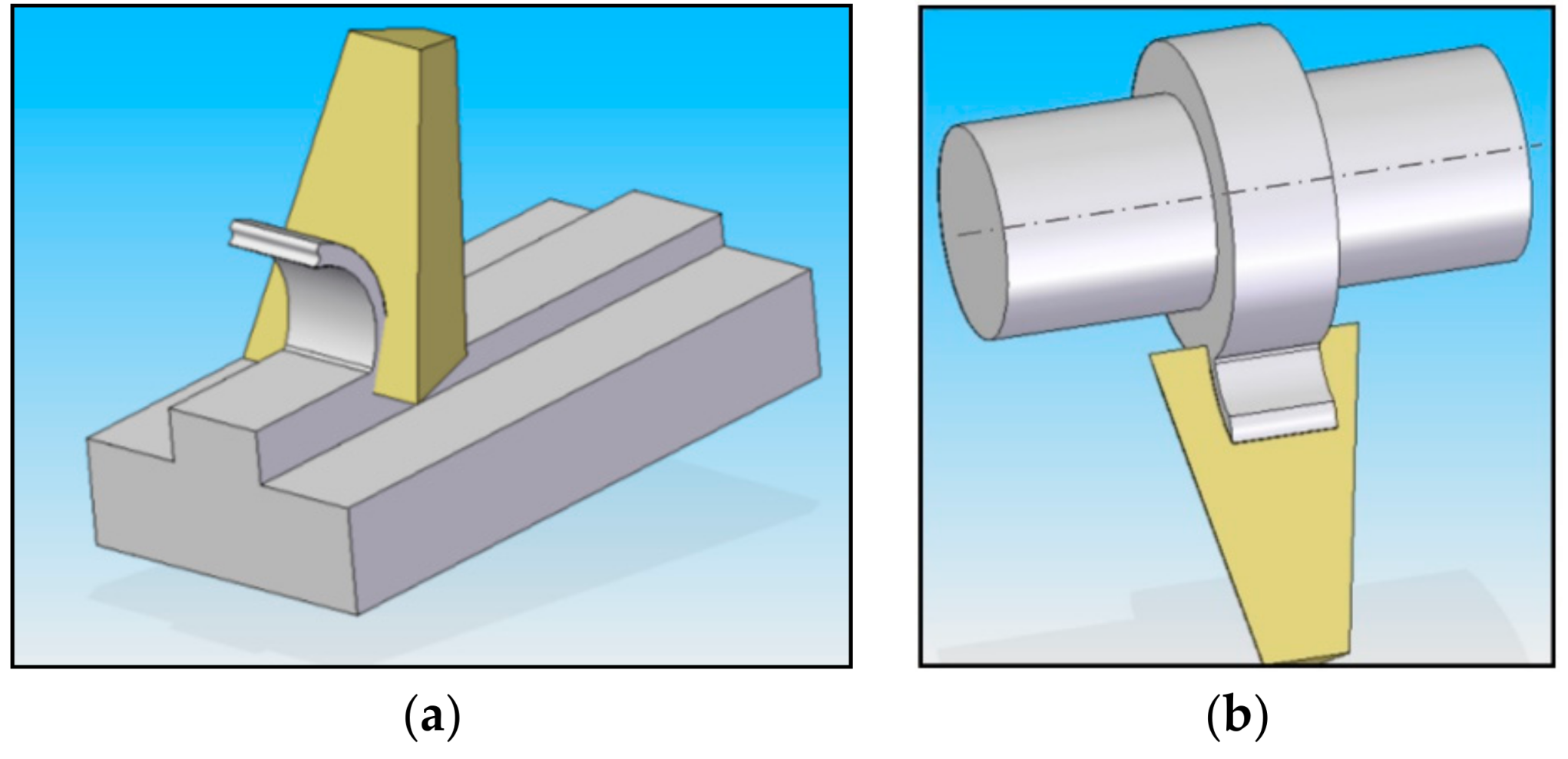
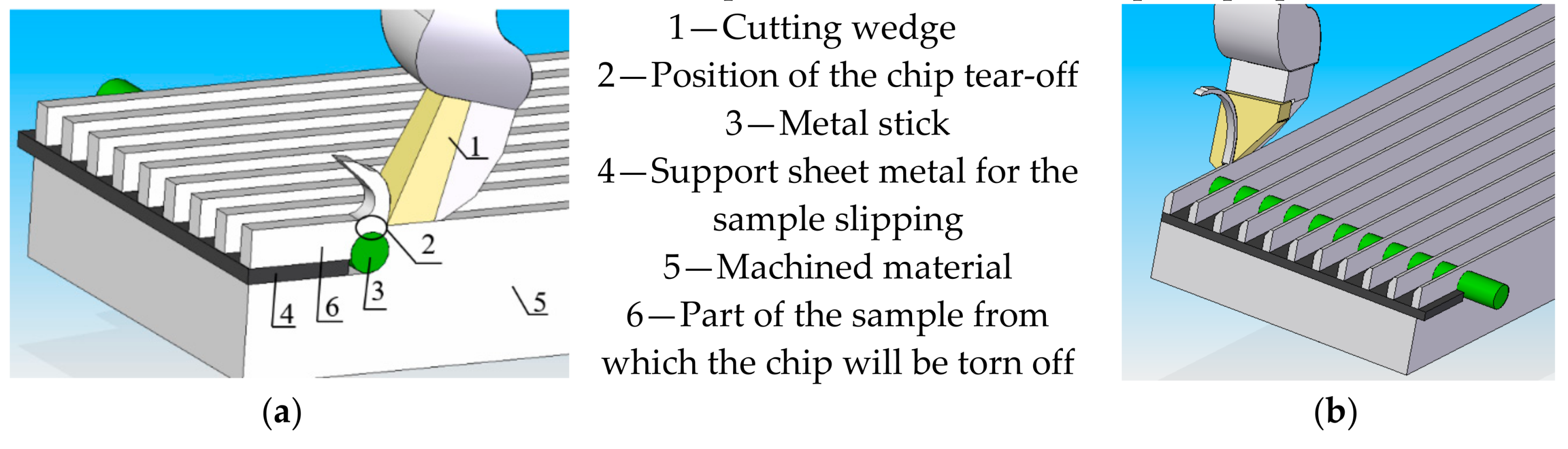
To study the chip characteristics, it is necessary to specify the type of machining by which the chip is forming. There are two different types of cutting: orthogonal (Figure 1a) and oblique (Figure 1b). Orthogonal cutting is a type of metal cutting in which the cutting edge of the wedge shape cutting tool is perpendicular to the direction of tool motion. In this cutting, the cutting edge is wider than the width of the cut. This cutting type is also known as 2D cutting because the force developed during the cutting can be plotted on a plane or can be represented by a 2D coordinate.
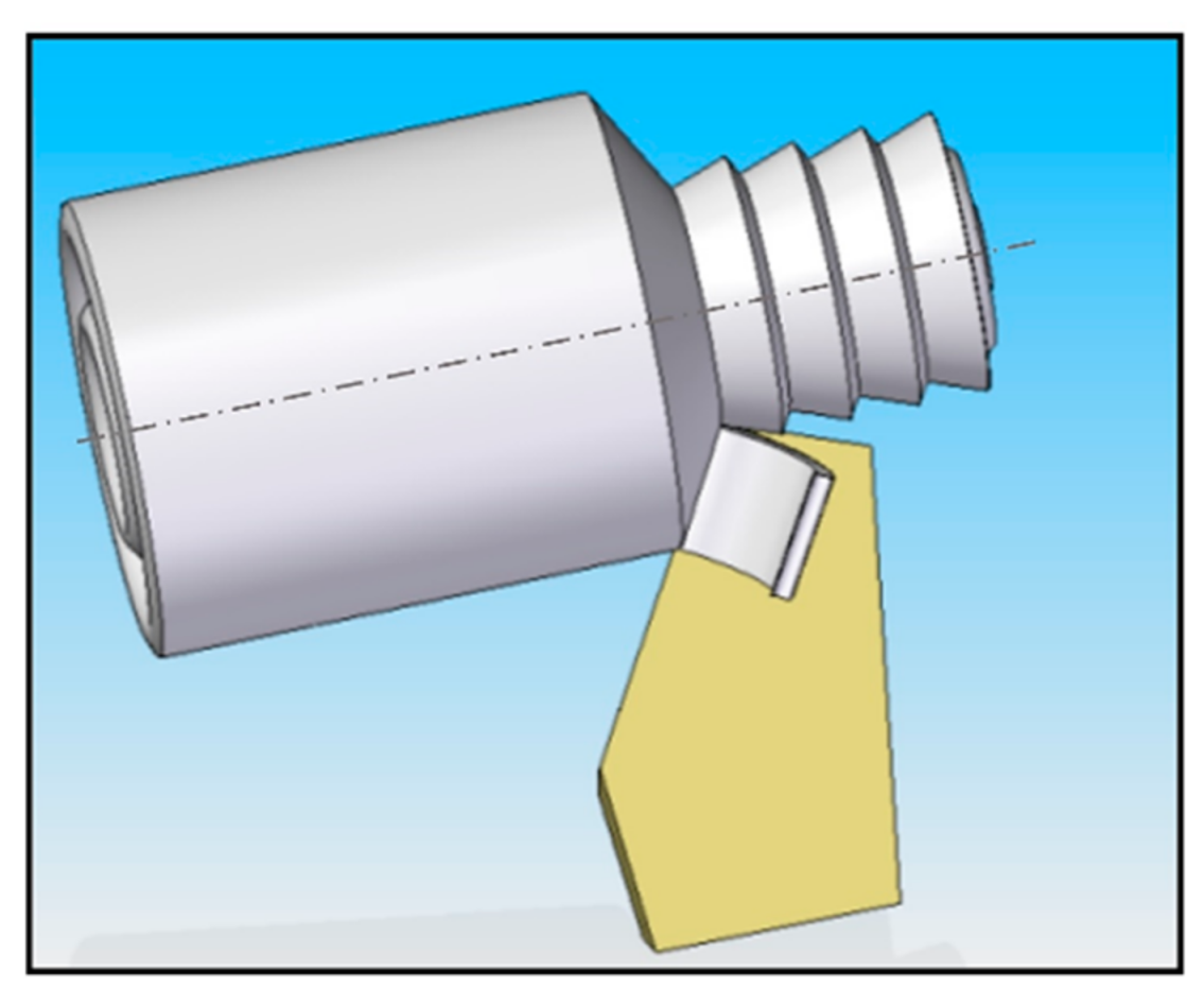
However, orthogonal cutting is only a particular case of oblique cutting and, as such, any analysis of orthogonal cutting can be applied to oblique cutting. Oblique cutting (Figure 2) is a common type of three-dimensional cutting used in the machining process [12].
In this type of machining, the cutting edge of the wedge shape makes an angle, except for the right angle, to the direction of tool motion. This will affect the cutting conditions and is also known as 3D cutting because the cutting force developed during the cutting process cannot be represented by 2D coordinates and 3D coordinates must be used to represent it.
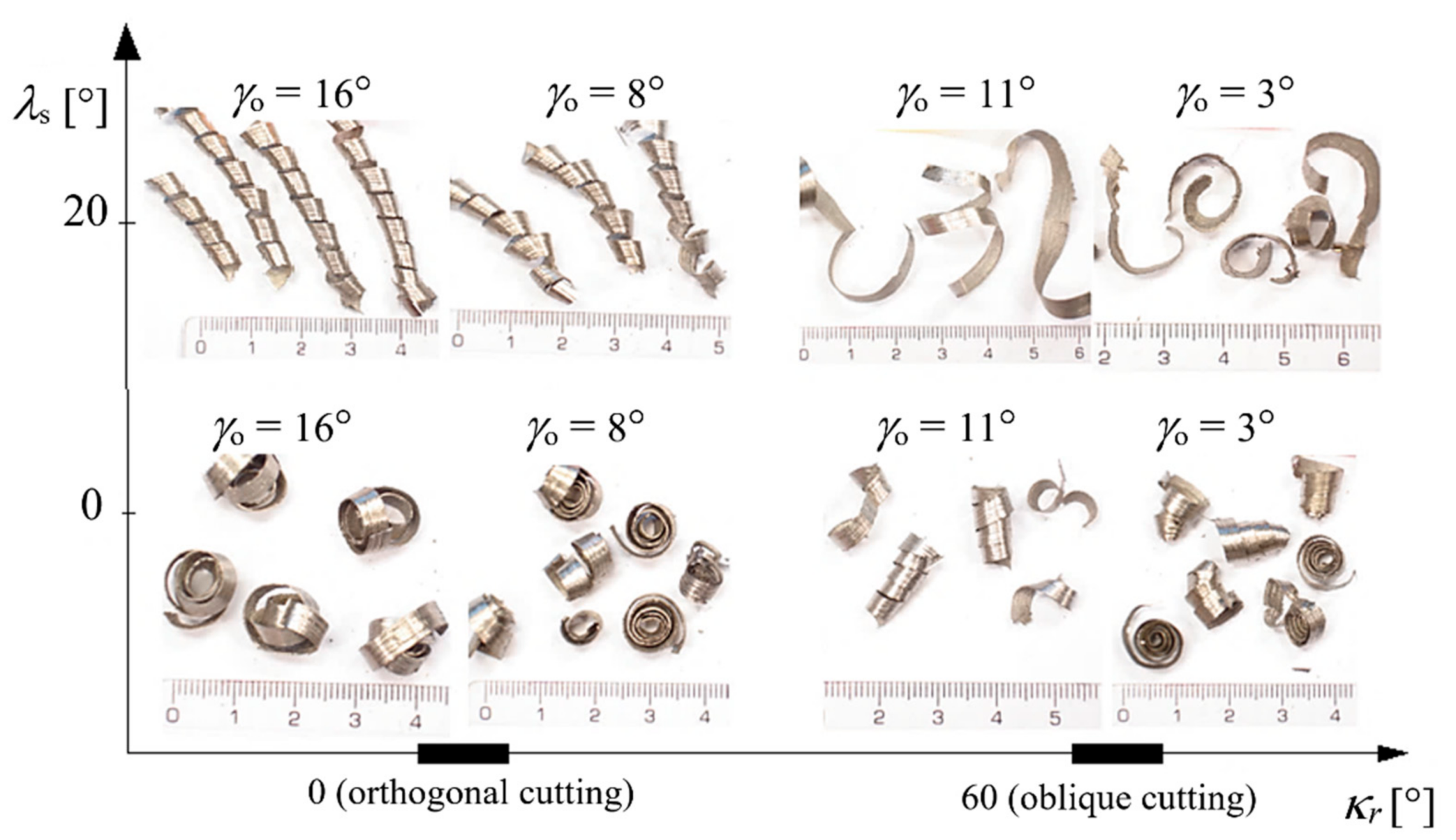
One of the most important parameters of oblique cutting is the chip flow angle. Stabler [13] stated that the chip flow angle is very close to the angle of obliquity. This rule has been accepted by many researchers and it has been considered to be a good predictor of the chip flow angle, e.g., as stated in [14,15,16]. However, Stabler’s rule does not take into account the mechanics of the cutting process, such as the influence of the shear angle and friction. In some special cases, it can cause larger errors. Luk [17] investigated the effect of cutting parameters on a chip flow angle and their study has been verified by Lin and Oxley [18] within their experimental investigation. Also, Russel and Brown [19] confirmed the influence of the normal rake angle on the chip flow. Shamoto and Altintas [20] developed a model for shear angle prediction in oblique cutting where the shear angle is specified by two components of the resultant force and by the chip flow angle. Moufki together with his colleagues [21] calculated the chip flow angle supposing that the friction force is collinear to the chip flow direction on the tool rake face. The effect of nose radius on the chip flow angle has been studied by investigators Usui [22] and Wang [23] using an iterative energy minimization method.
The chip characteristics during the milling process by varying the feed rates and the types of materials used were investigated by Prasetyo [24].
Chip morphology and microstructure were also studied by Hernández [25] in dry machining, where the influence of cutting speed and feed rate on various geometric chip parameters was carried out when cutting Ti6Al4V alloy.
Various methods by many researchers have been used to study chip geometry. Some of them analyzed chip geometry from an analytical point of view, resulting in the formulation of some theoretical models [26,27,28]. However, in these cases, many simplifications had to be made with regard to the complexity of the chip formation process and, hence, some of the real, practically obtained results have not correspond to the predictions of various parameters to set up a chip geometry, and the results were inaccurate [29,30,31]. Next, analyses of the chip formation used numerical models (finite element method, FEM) to simulate the chip generation process [32,33,34,35]. These models require a very good and precise definition of the boundary conditions; otherwise, the models are incomplete and vague [36,37].
Many of the studies that analyze the influence of one or two cutting parameters on chip geometry can be found in which the measured data were processed using four major statistical methods: regression, factor analysis, stochastic processes, and contingency table analysis [38,39,40,41,42]. Salem [43] and his coauthors have studied the chip formation at the machining of a hardened alloy X160CrMoV12-1 to obtain the optimal cutting conditions and to observe the different chip formation mechanisms. For the sake of simplicity, ANOVA (ANalysis Of VAriance) was used in this study to determine the influence of cutting parameters.
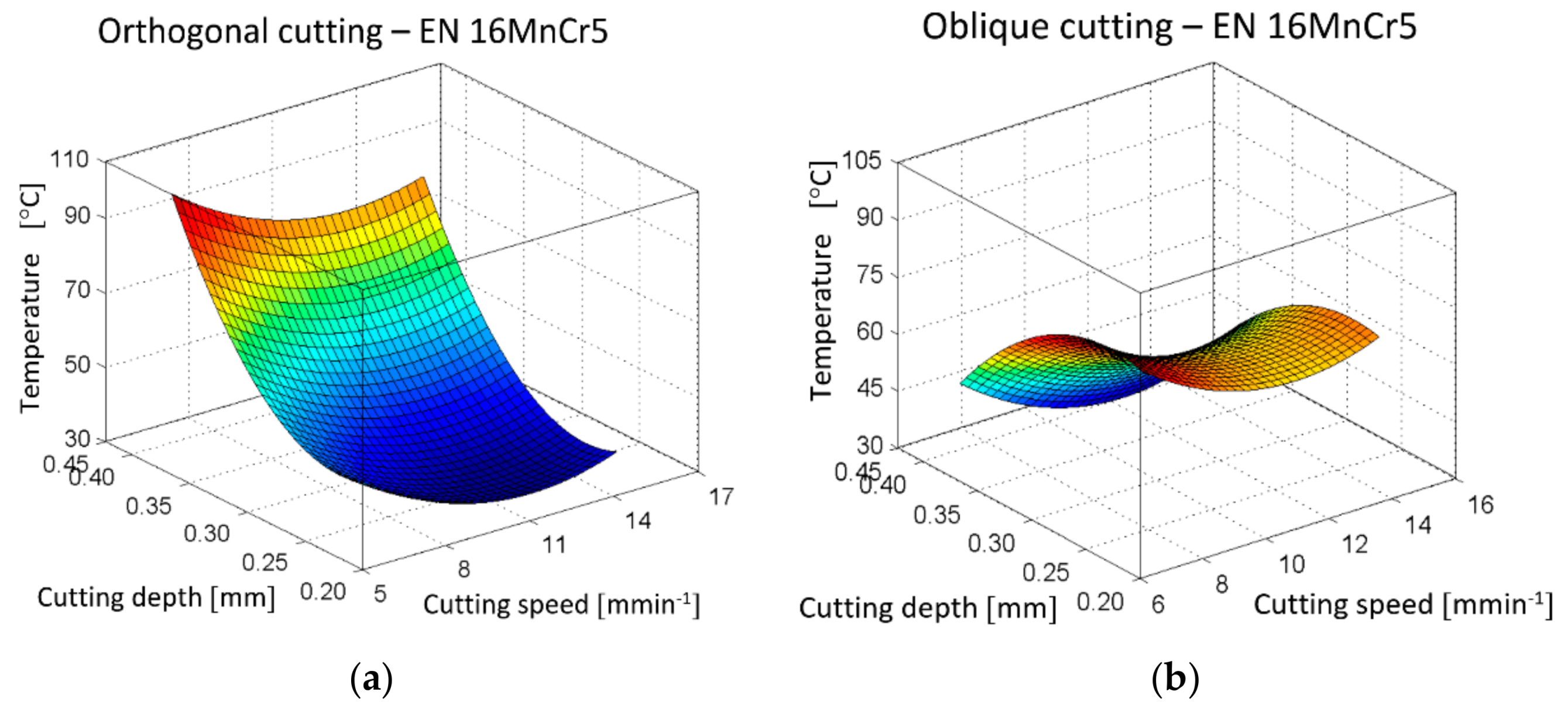
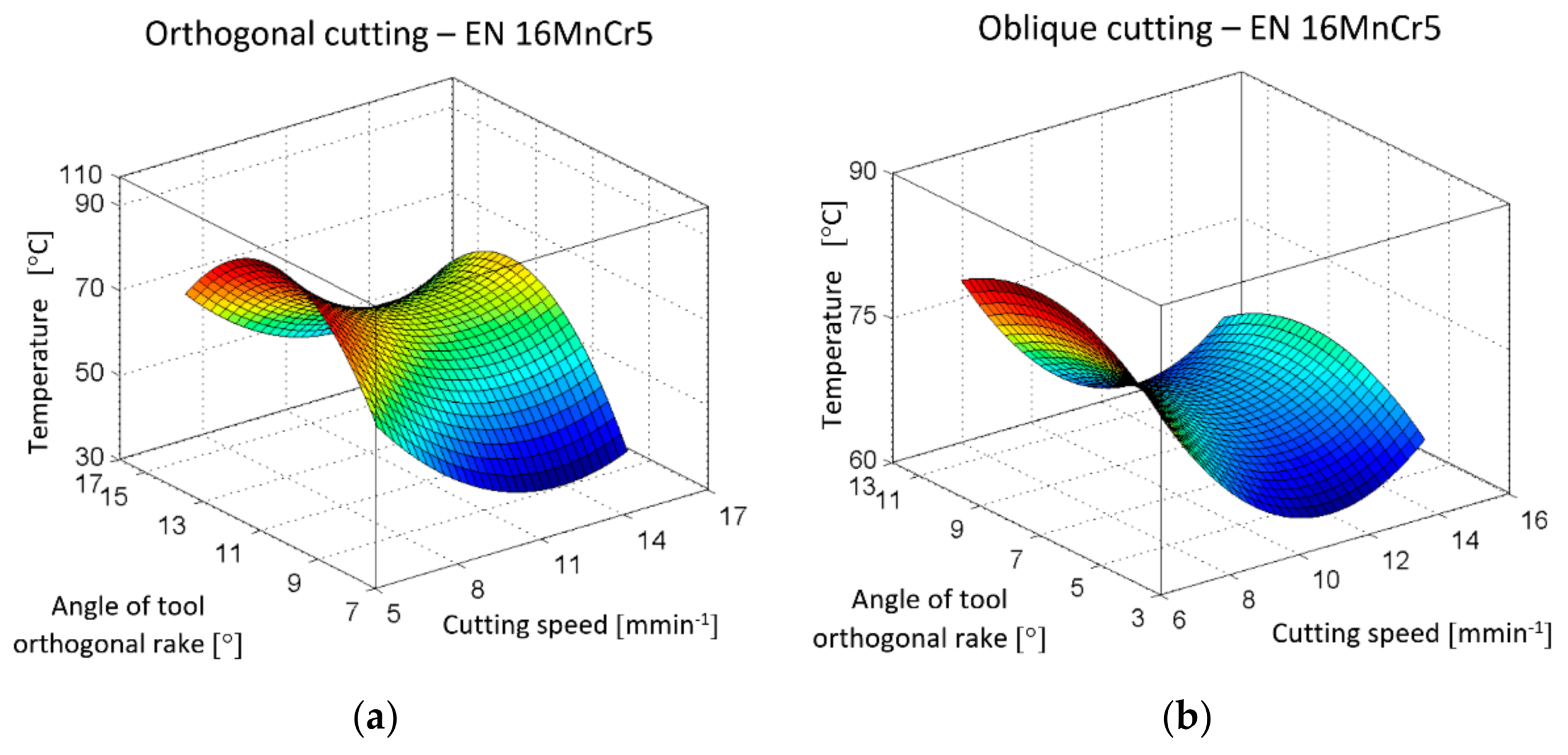
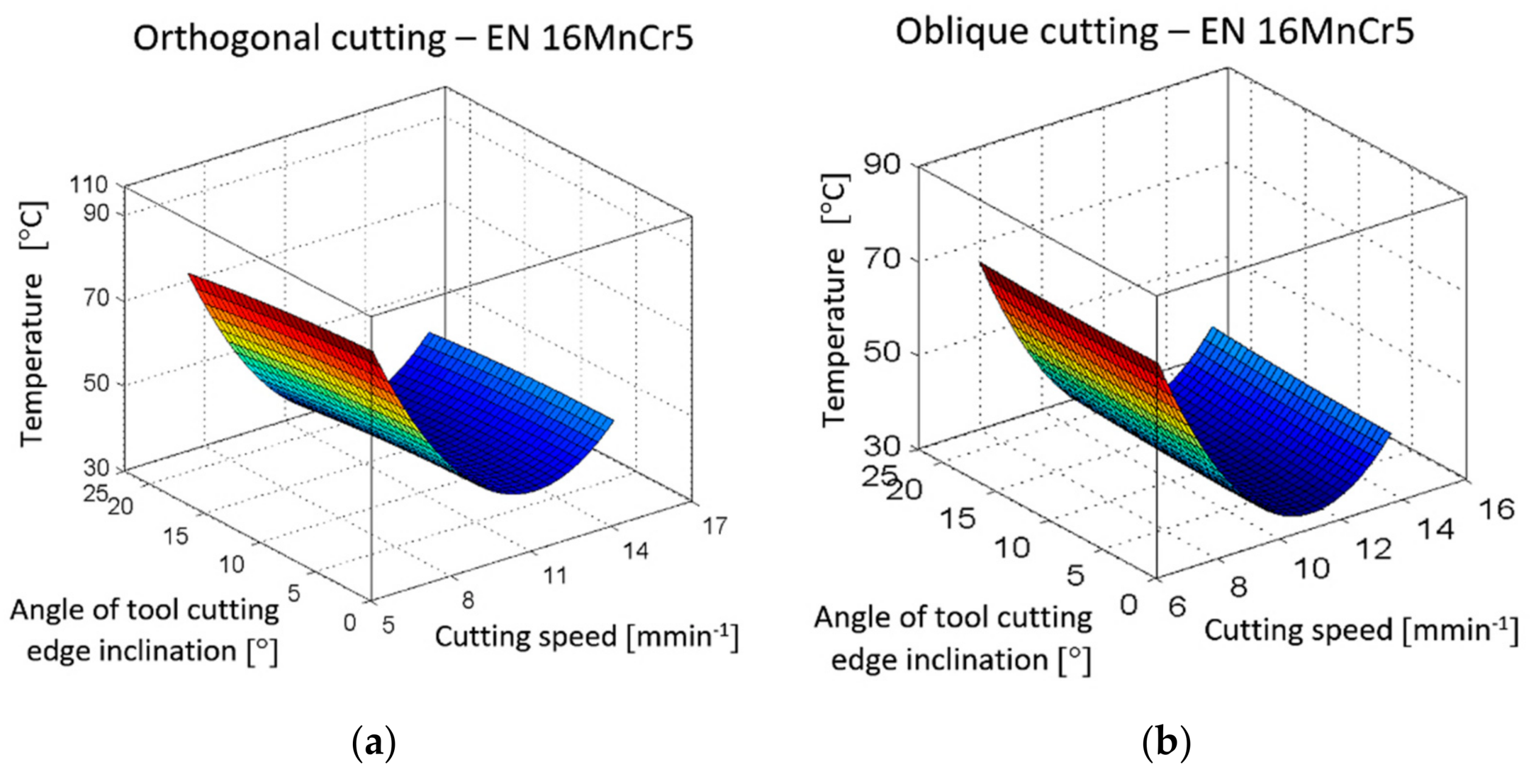
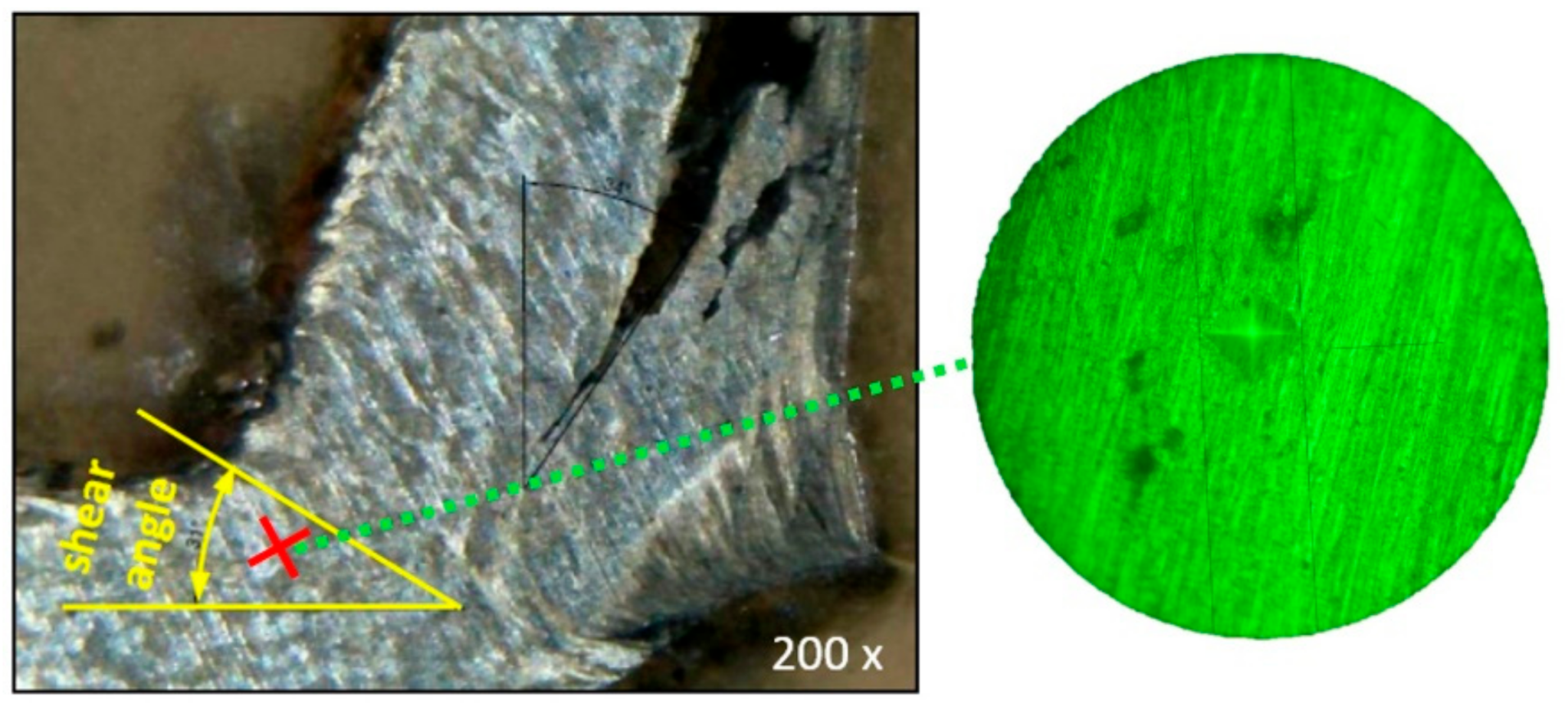
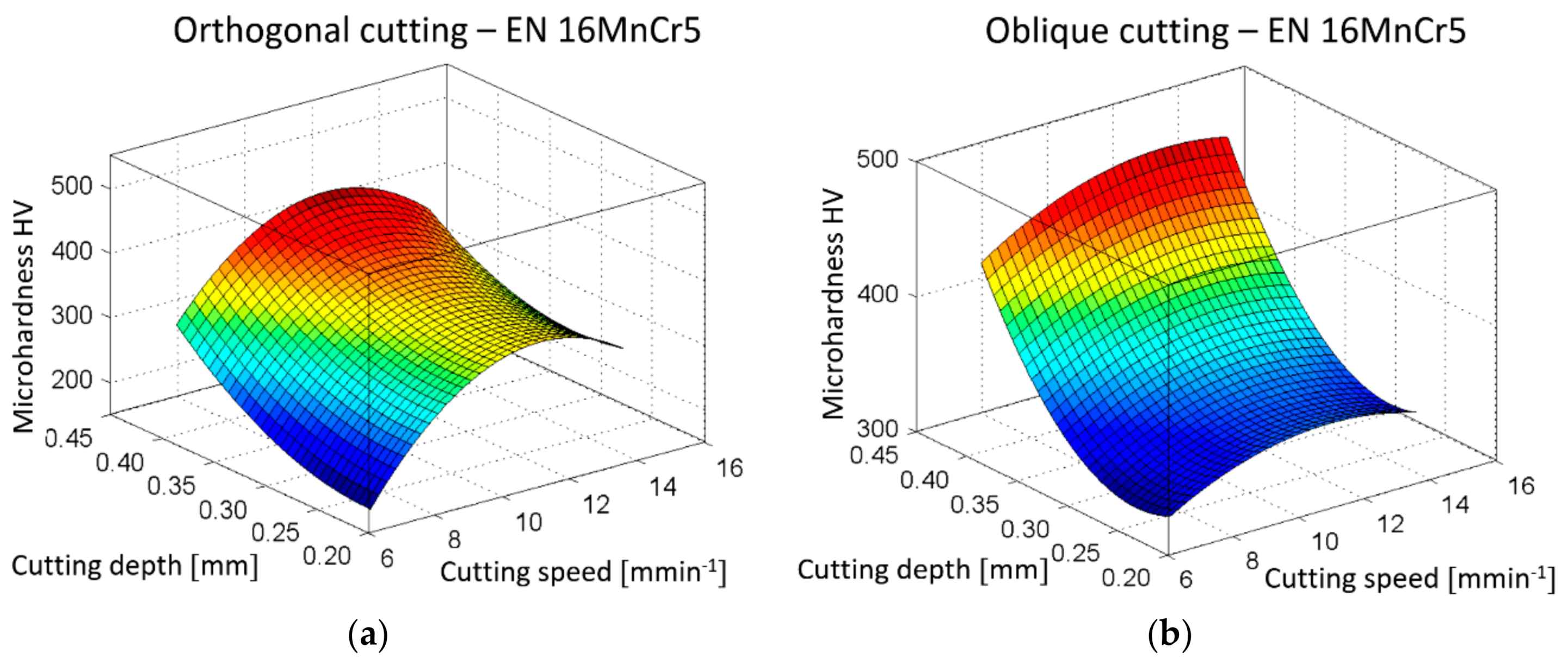
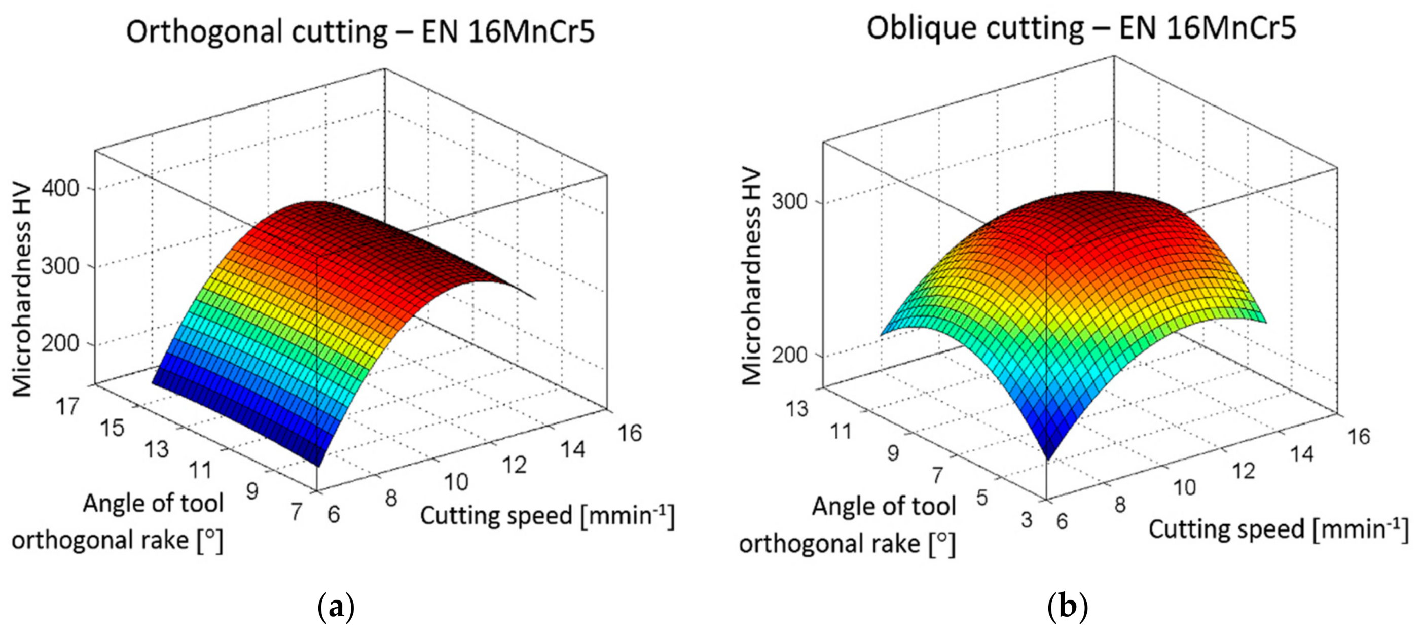
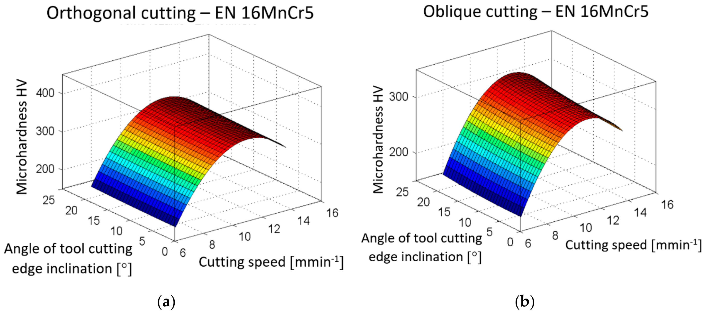
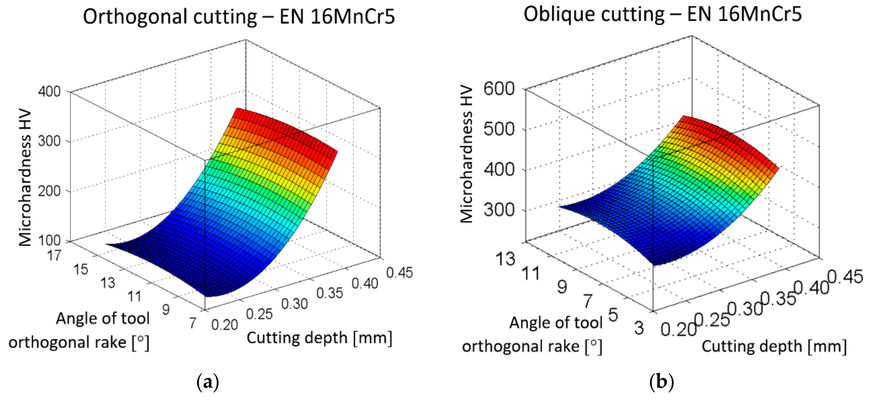
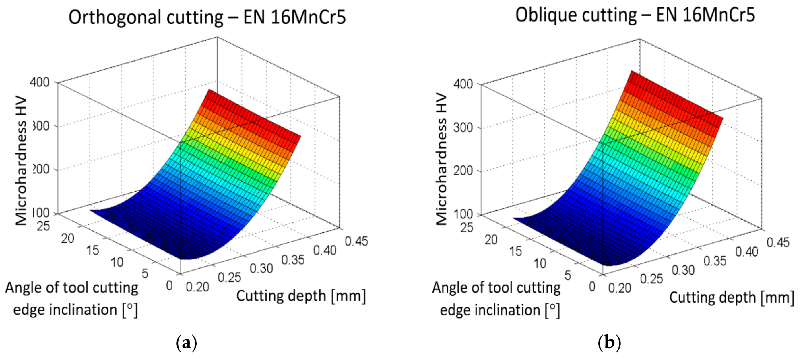
Currently, research of chip formation at slow-rate machining has been concerned with the influence of one or two factors on microhardness or temperature at chip root. Only a few studies have focused on chip formation in EN 16MnCr5 steel machining. The novelty of the presented study lies in the following: This research is more complex, while still considering the mutual connections among the four factors influencing chip forming in the cutting of EN 16MnCr5 steel in combination with observing and comparing the significance and influence of each individual factor in orthogonal and oblique cutting. For this reason, a three-level planned experiment was used for statistical evaluation of the obtained data. Based on the experimental study, several parametric models have also been developed that allow for the prediction of different temperatures or microhardness evolution at a chip root as a function of input parameters (cutting speed, cutting depth, and two geometry angles and of a tool λs and γo). Hereby, a new method of obtaining chip roots has been designed. The new method can be used to prevent changes in the microstructure of material by demonstrating a non-deformed and thermally uninfluenced chip root.

3. Materials and Methods

3.1. Cutting Tools, Machined Material, and Measuring Equipment

In the presented research, chip formation in orthogonal and oblique slow-rate machining has been experimentally investigated. For this comparative study, the technology of planing has been selected, in which a main sliding motion is performed on the workpiece. The machining process was carried out using the planer machine of HJ8A type (KOVOSCIT MAS Machine Tools, Sezimovo Ústí. Czech Republic).
Various combinations of cutting parameters, cutting speed vc, cutting depth ap, tool angles λs, and γo, were used in the experiments. The range of values was chosen based on industrial requirements. It is necessary to point out that lowest value of cutting speed was based on the speed limitations of the machine, where the highest value corresponds to 60% of the machine power. The range of cutting depth values ap was given by the planing machine, while the limitations were connected with a maximal cross-section of a chip. The values of rake angle γo were positive, in order to achieve the lowest possible specific cutting resistance values. The maximum angle value γo was selected in view of achieving sufficient bending strength of the cutting wedge. The angle of tool cutting edge inclination λs was chosen from zero up to a value that is four times higher than is commonly used in practice, in order to make the extent of the dependence under investigation large enough.
The planing necking tool type 32x20 ON 36550 HSS00 (PILANA Tools Ltd, Hulin, Czech Republic) was used at orthogonal cutting and straight roughing tool 32x20 ON 36500 HSS00 was used in oblique machining. Both types of cutting tools included brazed tips from high-speed steel with three different types of cutting-edge inclinations λs = 0°, 10°, and 20°. The used cutting tools and their geometries are presented in Table 1.
The angle of tool orthogonal rake γo and the angle of tool orthogonal clearance αo have been varied in the 2nd and 3rd phase of experiments to obtain a better view of chip formation and more reliable results. Changes in the angles’ values are organized in Table 2.
In order to verify the input angles of the tool orthogonal rake γo, preliminary input tests were performed. The tests were carried out using 3D measuring equipment RAPID CNC THOME (Zimmer Maschinenbau GmbH, Kufstein, Austria) that is shown in Figure 3, where details of the measuring process are also presented.
In the next experiment, the angle of tool orthogonal rake γo was measured for each of the cutting tools used. The protocols from measurements confirmed the values listed in Table 1 and Table 2, while the deviation of all measured values did not exceed 5% and the average angles of tool orthogonal rake for planing necking tools and straight roughing tools were γo = 8.138 = 8°2´0´´ or γo = 3.159 = 3°2´1´´, respectively.
The 1.7131 steel (EN 16MnCr5) was selected as a machined material; the chip formation of which has been subjected to some research. The alloyed carbon steel contains smooth deformable calcium aluminates encapsulated in manganese sulfide as an alternative to tough alumina oxide inclusions. It is suitable for cementing and for die forging; it is easily hot-formable and, after annealing, also cold-formable and easily machinable and weldable. This grade of steel is generally used for elements with a required core tensile strength of 800–1100 Nmm−2 and a good carrying resistance, e.g., piston bolts, camshafts, levers, and other automobile and mechanical engineering add-ons. The chemical composition of this steel, as given by European EN standards, has been verified by spectral analysis at the FMT TU Kosice with the seat in Presov, and is presented in Table 3.
The infrared thermometer, UNI-T UT305C, was used to measure the temperature based on the principle of infrared radiation emitted from a target surface.
Vickers microhardness was measured with a MICRO-VICKERS HARDNESS TESTER CV-403DAT (MetTech Ltd., Calgary, AB, Canada), which has the possibility to magnify the view 200–600×.
Etched specimens of chips were observed by means of Platinum USB digital microscope UM019 (Shenzhen Handsome Technology Co., Ltd., Shenzhen, China) with magnification 25–220×.

3.2. Design of the Composite Plan of the Experiment

The planned experiment, unlike the unplanned one, provides the maximum amount of information and performs the task very efficiently, e.g., in obtaining constants and exponents in empirical exponential dependencies that create a mathematical model [44].
In this study, the planned experiment at three levels (lower, basic, and upper) was implemented for the test preparation and the statistical method using a regression function has been used for data evaluation. The description of the experimental plan within this part of the article is given, due to a better understanding of measured data processing.
Based on the [44], the basic equations for statistical processing can be written in matrix:
Y = X b,
where
  • Y—column vector of measured quantities,
  • X—matrix of independent variables,
  • b—coefficient of a regression function.
The system of the normal equation (2) and a vector of the regression function coefficients (3) according to the matrix inversion can be respectively expressed in following way:
XT Y = XT X b,
b = XT X−1 XT Y.
It is necessary to consider that the complete three-level plan has a large scale of measurements expressed by N = 3k, where k is a number of variables and N is a number of measures (e.g., considering 5 variables within an experiment, where 243 measurements should be performed in total because N = 35 = 243). [45]
A reduced number of measurements for the dependencies described by functions of the second order,
y = b 0 x 0 + j = 1 N b j x j + u , j = 1 u j N b j x j x u + j N b j j x j 2 ,
can be achieved by means of the so-called second level compositional non-rotational plan [46], while the symbols in Equation (4) have the following meanings: xj is a variable (in the case of presented research it is one of the cutting parameters that will be varied), j, u are indexes that define a parameter, and bj is a j-th correlation coefficient.
The composition plan, in this case, consists of [46]:
  • A core of plan that can be
    • two-level 2k plan for k < 5, or as
    • shortened replica 2k-p for k ≥ 5, where p is a level of significance (Grubbs’ test);
  • The star points α with coordinates: (±α, 0, ..., 0); (0, ±α, 0, ..., 0); ...; (0, 0, ..., 0, ±α);
  • The measurements done at the basic level; or in the middle of the plan at x1 = x2 = ... = xk = 0 (the number of measurements in the middle of the plan is n0).
The total number of measurements is then [47]:
N = 2k + 2k + n0, if    k < 5, or
N = 2k-p+ 2k +n0, if    k ≥ 5.
In practical implementation, n0 = 1 [48] is chosen, with no boundary. The matrix of the orthogonal composition plan for k, α, and n0 is given in Table 4. In its general form, it is not orthogonal because the relations on the left sides of Equations (6) and (7) differ from zero:
i = 1 N x o i x j i 2 0 ,
i = 1 N x j i 2 x u i 2 0 .
The matrix is converted to orthogonal shape by quadratic variables exchanging [49]:
x j = x j 2 1 N i = 1 N x j i 2 = x j 2 x ¯ j 2 ,
This is why
i = 1 N x o i x j i = i = 1 N x j i 2 N x ¯ j 2 = 0 ,
i = 1 N x j i x u i 0 .
The regression function correlation coefficients in (4) are independent because of the orthogonality of the experimental matrix, and they are specified by the following relations, (11)–(14):
b j = i = 1 N x j i y i i = 1 N x j i 2 = i = 1 N x j i y i 2 k + 2 a 2 ,
b u j = i = 1 N x j i y i i = 1 N x j i 2 = i = 1 N x j i y i 2 k ,
b j j = i = 1 N x j i y i i = 1 N ( x j i ) 2 ,
b o = 1 N i = 1 N x o i y i ,
Hence, the second stage regression function (4) is then given by Equation (15):
y = b o + b 1 x 1 + b 2 x 2 + + b k x k + b 12 x 1 x 2 + b ( k 1 ) k x ( k 1 ) x k + b 11 ( x 1 2 x ¯ 1 2 ) + b k k ( x k 2 x ¯ k 2 ) ,
where the constant member of the regression function is corrected by quadratic variables (8) in the form of
b o = b o b 11 x ¯ 1 2 b k k x ¯ k 2 .
Using Grubbs’ testing criteria, the outliers from the measured values have been specified for every group of measurements. The following equations, (17)–(19), have had to be kept.
H i = | T i k T i ¯ | S T i < H p ( m ) ,
while
T i ¯ = k = 1 m T i k m ,
S T i = 1 m 1 · k = 1 m ( T i k T i ¯ ) 2 ,
where
  • m—a number of evaluated measurements within the Grubbs´ test;
  • Tik—measured value of k-th issue in the i-th group, k = 1, 2, 3; i = 1, 2, ..., 24, 25;
  • T i ¯ —average value of measured issues of the i-th group; calculation according to the equation;
  • STi —standard deviation of measured issue of the i-th group;
  • Hp(m)—critical value of Grubbs´ testing criteria for m values (m = 3), where p is a level of significance and usually it is Hp(m) = 0.05.
The calculation of the regression coefficients was performed using MATLAB calculation software (The MathWorks, Inc., Natick, MA, USA), while the significance of the coefficients of the function y = log T was tested according to Student’s test criterion.
The adequacy of regression function was assessed according to the Fisher–Snedecor test criterion F < F0.05 (f1, f2), where the degrees of freedom f1 = Nq (q is a number of significant coefficients) and f2 = N(m − 1).

3.3. Process of Obtaining Samples

To track changes in the zone of chip forming, the machining process must be stopped immediately, thus interrupting tool and workpiece contact. A reliable method to achieve the immediate stop of the machining process has been developed in this research and is based on observation of the chip end produced upon interrupted cutting, e.g., in planing or face milling. As the tool leaves the cutting zone, the end of the chip is “torn off”, as shown in Figure 4.
The reasons mentioned above led to the design of a new method for chip root acquisition by modifying the end of the workpiece according to Figure 5. The goal of the proposed method and the special workpiece design was to avoid deformation and thermal influence of the material which could cause the changes in the microstructure of a material. For this reason, a cooling medium JCK PS was used, at a concentration of 5%, for all operations within the workpiece preparation.
At the point of departure of tool “1” from the engagement, a groove has been cut where the sheet metal insert “4” has been put in to prevent deformation of the specimen during the rupture. A hole of 8 mm diameter has been drilled behind the groove and a metal rod “3” has been inserted therein, which prevents the hole from deforming. When the tool passes above the metal rod, the section “2” becomes narrower and the material ruptures, which is similar to the tensile test. Sample “6” is rapidly thrown up in the direction of tool movement at a rate greater than cutting speed and on the sample; and the plastic deformation state corresponding to the actual cutting speed is captured.
The experiment, in which chips were obtained, was carried out on a planer without the use of cooling, since the cutting length of the tool path was about 200 mm and, thus, the tool and workpiece were not overheated.
Within the experimental study, the variables according to the Table 5 have been taken into account, while the codes for the specific values of individual variables are referred to in Table 6.

4. Results and Discussion

4.1. Types of Chips

During machining, different types of chips have been created. Cutting speed was not observed to have a significant impact on the chip shape, while the depth of the cut affected the radius of curvature of the chip (when increasing the thickness of the cut layer, the radius of curvature of the chip was increased). Figure 6 shows an example of the dependence of chip shapes on cutting speed vc and cutting depth ap at tool angles for γo = 16°, λs = 0°, κr = 0°.
As for tool geometry, the angle of the orthogonal tool rake γo at the minimum values caused formation of a crumbly chip and the angle of inclination of the main cutting edge λs has influenced the chip shape in the way that is graphically presented in Figure 7.
A shorter chip was created at a zero angle of inclination of main cutting edge when comparing it with the angle of inclination of the main cutting edge of 20°. At the same time, at a 20° angle of inclination of the cutting edge, the chip obtained a so-called chamfer along the edges, which is adequate to the angle of inclination of the main cutting edge and, thus, the chip was compressed in the direction of λs inclination and acquired the character of a spiral chip. In orthogonal cutting, at which κr = 0° and λs = 0°, a spiral flat chip was formed, which in some cases passed into a spiral conical chip. For κr = 0° and λs = 20°, a conical–helical long chip was constituted. In oblique cutting, where κr = 60° and λs = 0°, a conical–helical short chip was generated. At κr = 60° and λs = 20°, the chip shape changed to a coiled chip, while at a rake angle γo = 11°, it was a tubular coiled chip and at γo = 3° it was a strip coiled chip.
The shrinkage factor K and the segment ratio rc at the planing can be calculated with Equations (20) and (21), respectively, where hc is the chip width, ap is cutting depth, γ is the tool rake angle, and Φ is the shear angle [1,12,50,51]:
K = h c a p = cos ( Φ γ ) sin Φ ,
r c = 1 K .
The values of the shrinkage factor K achieved within the experimental study are organized in Table 7.

4.2. Temperature Measuring

The temperature in a cutting zone was measured by means of the infrared thermometer UNI-T UT305C. The values of measured temperature with the coded matrix (explained in the Design of the Composite Plan of the Experiment, Section 3.2.) are shown in Table 8.
Measured data were statistically processed. According to the Grubbs’ testing criterion, it could be stated that the measured values have not been burdened by grave mistakes.
Homogeneity of the variance of measured temperatures were tested according to Cochrane´s criterion by the relation
G = S m a x 2 i = 1 N S i 2 = 0.025877 0.111027 = 0.23307 .
The critical value of Cochrane’s criterion G0,05(f1, f2), given by [22], is G0.05(f1,f2) = 0.2705, where the degrees of freedom were f1 = N = 25 and f2 = m − 1 = 3 − 1 = 2.
Since G < G 0 , 05 ( f 1 , f 2 ) → the criterion has been satisfied and it means that the variations within parallel measurements are homogeneous.
The coefficients of regression functions have been calculated using the software MATLAB and their significance was tested according to the Student’s criterion. The regression functions (23) and (24) have been built. According to the Fisher–Snedecor-tested criterion, they describe the experiment adequately, while the reliability of the relations is R2 = 0.91 and 0.94, respectively:
a)
For orthogonal cutting:
y = 3.2502 x 0 3.7533 x 1 + 3.1462 x 2 + 4.2035 x 3 0.1865 x 4 0.1553 x 1 x 2 + 0.3467 x 1 x 3 + 0.0385 x 1 x 4 + 0.4106 x 2 x 3 0.0202 x 2 x 4 + 0.0304 x 3 x 4 + 1.6486 x 1 2 + 3.1542 x 2 2 2.8264 x 3 2 0.042 x 4 2
b)
For oblique cutting:
y = 2.9212 x 0 10.4247 x 1 7.2462 x 2 + 4.4859 x 3 + 0.1295 x 4 0.4264 x 1 x 2 0.2621 x 1 x 3 + 0.0625 x 1 x 4 + 0.5108 x 2 x 3 + 0.0251 x 3 x 4 + 5.4295 x 1 2 6.6225 x 2 2 2.6781 x 3 2 + 0.0676 x 4 2
Based on the measured data, the following dependencies have been evaluated for both orthogonal and oblique cuttings:
  • The dependency of temperature T on cutting speed vc and on the cutting depth ap;
  • The dependency of temperature T on cutting speed vc and angle of tool orthogonal rake γo;
  • The dependency of temperature T on cutting speed vc and on the angle of tool cutting edge inclination λs.
The dependencies are presented in Figure 8, Figure 9 and Figure 10.
It can be seen from the dependence of the temperature on the cutting speed and on the cutting depth at orthogonal machining (Figure 8a) that the cutting depth has an incomparably stronger influence than the cutting speed. By contrast, in oblique cutting (Figure 8b), the impact of cutting depth is milder, so the effect of cutting speed is more noticeable. Maximum temperature values were reached at a maximum cutting depth during orthogonal cutting and at a minimum cutting depth during oblique cutting.
The angle of tool orthogonal rake γo at the machining of manganese chromium steel has a similar character in both cutting methods (Figure 9), while the highest values of temperature have been measured at mean values of γo. The influence of cutting speed also has the same character at both orthogonal and oblique cutting, and the maximum temperature has been reached at the minimal value of cutting speed.
The dependence of the cutting speed and tool cutting edge inclination λs on the temperature is almost identical in both orthogonal and oblique cutting (Figure 10). The influence tool cutting edge inclination is almost imperceptible in both cases compared to the impact of speed.

4.3. Measurement of Microhardness HV According to Vickers

The next evaluated parameter was microhardness according to Vickers. The measurements were carried out on samples of chip root at a load of 200 g during intervals of 10 s, according to the standard STN EN ISO 6507-1. Vickers microhardness evaluation was performed based on the experimental plan design, similarly as at the temperature measuring. The character of the matrix for experimental composition plan was designed for both cutting methods, where four matrix shapes have been evaluated resulting in four dependencies pictured by means of surface plots. The hardness of the material was measured in the area of shear angle Φ that is shown in Figure 11; also, a diamond body imprint with magnification 600× is displayed here in detailed view. The obtained values are organized in Table 9.
Similarly as for measurements of temperature and share angle, the regression functions (25) and (26) for the evaluation of microhardness of chip root have been defined. The reliabilities R2 of the dependencies for both types of machining (orthogonal and oblique) were 0.92 and 0.93, respectively. Regression functions are specified by the following equations:
a)
For orthogonal cutting:
y = 5.0009 x 0 + 17.2807 x 1 + 5.2179 x 2 0.575 x 3 + 0.1881 x 4 1.5626 x 1 x 2 0.1588 x 1 x 3 + 0 , 0397 x 1 x 4 0.2036 x 2 x 3 0.0623 x 2 x 4 0.0376 x 3 x 4 9.2084 x 1 2 + 3.3134 x 2 2 0.4774 x 3 2 + 0.0915 x 4 2
b)
For oblique machining:
y = 1.2673 x 0 + 7.7671 x 1 + 9.0532 x 2 + 5.5376 x 3 + 0.2281 x 4 + 0.7224 x 1 x 2 0.2077 x 1 x 3 + 0.0846 x 1 x 4 0.6964 x 2 x 3 3.6942 x 1 2 + 8.2721 x 2 2 3.8696 x 3 2 + 0.1162 x 4 2
Based on the relations (23) and (24) formulated above, the dependencies of the microhardness HV on individual variables were plotted. They are presented in Figure 12, Figure 13, Figure 14, Figure 15 and Figure 16.
The influence of cutting depth and cutting speed was the most significant effect of the four variable parameters which changed the microhardness HV. In oblique cutting (Figure 12b), the effect of the cutting depth is more pronounced than the effect of the cutting speed compared to its effect in orthogonal cutting (Figure 12a). Maximum microhardness values were achieved at maximum cutting depth and at medium and higher cutting speeds.
The effect of the rake angle on orthogonal cutting (Figure 13a) is almost imperceptible compared to the cutting speed. In oblique cutting (Figure 13b), the angle of tool orthogonal rake has the same significant impact as the cutting speed, and maximum microhardness HV was achieved at its mean values.
In the interaction of the angle of the tool cutting edge inclination and the cutting speed, the influence of the inclination angle on a change of the microhardness HV appears to be zero compared to the cutting speed in both cutting methods (Figure 14).
The interaction of the cutting depth and, also, the angle of the tool orthogonal rake have the same nature regarding the effect on microhardness in both cutting methods (Figure 15). The angle of tool orthogonal rake is less pronounced with respect to the cutting depth and the maximum microhardness values were measured at mean rake angle values and maximum cutting depth. Almost the same statement can be made for the effect of the cutting depth and the angle of tool cutting edge inclination on microhardness HV, as shown in Figure 16.

5. Conclusions

The chip formation in cutting processes at relatively low cutting speeds depends on the conditions of the cutting, the cutting tool and, to a large extent, on the machined material. EN 16MnCr5 manganese chromium steel was chosen as the material for this study. The experiments were carried out on specially modified workpieces for orthogonal and oblique machining (planing), in which the tool geometry and cutting conditions were changed. When changing individual parameters, the shape of chip forming was observed, the temperature was measured in the cutting area, and the Vickers HV microhardness was measured in the shear angle area. The results were statistically processed, and statistical regression dependence was constructed from all measured values.
The influence of individual parameters on the chip shape during machining of EN 16MnCr5 steel can be summarized in the following ways:
  • The effect of the change in cutting speed in a given experiment on the chip shape appeared to be insignificant.
  • The angle of the orthogonal tool rake caused a crumbly chip formation at minimum values, rather than at the maximum values.
  • The cutting depth affected the radius of curvature of the chip. When increasing the thickness of the cut layer, the radius of chip curvature increased.
Based on the experiments, it could be stated that the most noticeable influence on the shape change of the chips is achieved by the angle of inclination of the main cutting edge λs and the tool cutting edge angle κr. At a zero angle of inclination of the main cutting edge, a shorter chip was produced than at an angle of inclination of the main cutting edge of 20°. At the same time, at a 20° angle of inclination of the cutting edge, the chip obtained a so-called chamfer along the edges, which is adequate to the angle of inclination of the main cutting edge, thus compressing the chip in the inclination direction of λs leading to the shape obtaining characteristics of a spiral chip.
By measuring the temperature in the cutting area (for both orthogonal and oblique cutting), the most significant influencing parameter for temperature change was found to be the depth of the cut. This was followed by cutting speed and a forehead angle, whereas the influence of the angle of inclination of the main cutting edge appeared to be insignificant. The maximum temperature during orthogonal cutting was reached at the maximum cutting depth, but in oblique cutting, the maximum temperature was reached at minimum cutting depth. In both cases, cutting at maximum temperature was characterized by mean values of the angle of tool orthogonal rake.
When measuring Vickers HV microhardness in the shear angle area, the significance of parameters was different. In orthogonal cutting, the highest microhardness was achieved at maximum cutting speed, while in oblique cutting, the maximum microhardness HV was achieved at maximum cut depth values.

Author Contributions

Conceptualization, K.M. and A.S.; methodology, K.M., P.P.M. and A.S.; software, L.H. and A.B.; validation, L.H. and A.B.; investigation, K.M. and P.P.M.; resources, K.M. and M.U.; data curation, M.U.; writing—original draft preparation, K.M.; writing—review and editing, P.P.M.; supervision, K.M.

Funding

This research was funded by Ministry of Education of the Slovak Republic by grant KEGA 007TUKE-4/2018.

Acknowledgments

The article was prepared thanks to the direct support of the Ministry of Education of the Slovak Republic by grant KEGA 007TUKE-4/2018 and thanks to European Regional Development Fund in the Research Centre of Advanced Mechatronic Systems project, project number CZ.02.1.01/0.0/0.0/16_019/0000867 within the Operational Programme Research, Development and Education.

Conflicts of Interest

The authors declare no conflict of interest.

Nomenclature

γoangle of tool orthogonal rake (°)
λsangle of tool cutting edge inclination (°)
αoangle of tool orthogonal clearance (°)
κrtool cutting edge angle (°)
κr´tool minor (end) cutting edge angle (°)
εrtool included angle (°)
Φshear angle (°)
apdepth of cut (mm)
vccutting speed (mmin−1)

References

  1. Merchant, M.E. Mechanics of the metal cutting process. I. orthogonal cutting and a type 2 chip. J. Appl. Phys. 1945, 16, 267. [Google Scholar] [CrossRef]
  2. Lee, E.H.; Shaffer, B.W. The theory of plasticity applied to a problem of machining. J. Appl. Mech. 1951, 73, 405. [Google Scholar]
  3. Palmer, W.B.; Oxley, P.L.B. Mechanics of metal cutting. Proc. Inst. Mech. Eng. 1959, 173, 623. [Google Scholar] [CrossRef]
  4. Von Turkovich, B.F. Dislocation theory of shear stress and strain rate in metal cutting. In Proceedings of the 8th International Machine Tool Design and Research Conference, Manchester, UK, September 1967; pp. 531–542. [Google Scholar]
  5. Okushima, K.; Minato, K. On the behaviors of chips in steel cutting. Bull. JSME. 1959, 2, 58–64. [Google Scholar] [CrossRef]
  6. Usui, E.; Hoshi, K. Slip-line fields in metal machining which involve centered fans. In Proceedings of the International Production Engineering Research (ASME Conference), Pittsburgh, PA, USA, September 1963; pp. 61–71. [Google Scholar]
  7. Johnson, W.; Sowerby, R.; Haddow, J.B. Plane-Strain Slip-line Fields: Theory and Bibliography; Edward Arnold Ltd.: London, UK, 1970. [Google Scholar]
  8. Fang, N.; Jawahir, I.S.; Oxley, P.L.B. A universal slip-line model with non-unique solutions for machining with curled chip formation and a restricted contact tool. Int. J. Mech. Sci. 2001, 43, 570–580. [Google Scholar] [CrossRef]
  9. Young, H.T.; Mathew, P.; Oxley, P.L.B. Allowing for nose radius effects in predicting the chip flow direction and cutting forces in bar turning. Proc. Inst. Mech. Eng. 1987, 201, 213–226. [Google Scholar] [CrossRef]
  10. Zhou, L.; Guo, H.; Rong, Y. Machining chip breaking prediction. In Proceedings of the SME 4th International Machining & Grinding Conference, Troy, MI, USA, 7–10 May 2001; p. 601. [Google Scholar]
  11. Toulfatzis, A.I.; Pantazopoulos, G.A.; David, C.N.; Sagris, D.S.; Paipetis, A.S. Final heat treatment as a possible solution for the improvement of machinability of pb-free brass alloys. Metals 2018, 8, 575. [Google Scholar] [CrossRef]
  12. Vasilko, K. New experimental dependence of machining. Manuf. Technol. 2014, 14, 111–116. [Google Scholar]
  13. Stabler, G.V. The chip flow law and its consequences. In Advances in Machine Tool Design and Research; Tobias, S.A., Koenigsberger, F., Eds.; The Macmillan Press Ltd.: London, UK, 1964; pp. 243–251. [Google Scholar]
  14. Moufki, A.; Dudzinski, D.; Molinari, A.; Rausch, M. Thermo-viscoplastic modelling of oblique cutting: Forces and chip flow predictions. Int. J. Mech. Sci. 2000, 42, 1205–1232. [Google Scholar] [CrossRef]
  15. Lin, Z.C.; Lin, Y.Y.A. Study of an oblique cutting model. J. Mater. Process. Technol. 1999, 86, 119–130. [Google Scholar] [CrossRef]
  16. Becze, C.E.; Elbestawi, M.A.A. Chip formation based analytical force model for oblique cutting. Int. J. Mach. Tools Manuf. 2002, 42, 529–538. [Google Scholar] [CrossRef]
  17. Luk, W.K. The direction of chip flow in oblique cutting. Int. J. Proc. Res. 1972, 10, 67–76. [Google Scholar] [CrossRef]
  18. Lin, G.C.I.; Oxley, P.L.B. Mechanics of oblique machining: predicting chip geometry and cutting forces from workmaterial properties and cutting conditions. Proc. Inst. Mech. Eng. 1972, 186, 813–820. [Google Scholar] [CrossRef]
  19. Russell, J.K.; Brown, R.H. The measurement of chip flow direction. Int. J. Mach. Tool Des. Res. 1966, 6, 129–138. [Google Scholar] [CrossRef]
  20. Shamoto, E.; Altintas, Y. Prediction of Shear Angle in Oblique Cutting with Maximum Shear Stress and Minimum Energy Principles. J. Manuf. Sci. Eng. 1999, 121, 399–407. [Google Scholar] [CrossRef]
  21. Moufki, A.; Molinari, A.; Dudzinski, D. Modelling of orthogonal cutting with a temperature dependent friction law. J. Mech. Phys. Solids. 1998, 46, 2103–2138. [Google Scholar] [CrossRef]
  22. Usui, E.; Hirota, A.; Masuko, M. Analytical prediction of three dimensional cutting process. Part 1: basic cutting model, an energy approach. J. Eng. Ind. 1977, 100, 222–228. [Google Scholar] [CrossRef]
  23. Wang, J. Development of a chip flow model for turning operations. Int. J. Mach. Tools Manuf. 2001, 41, 1265–1274. [Google Scholar] [CrossRef] [Green Version]
  24. Prasetyo, L.; Tauviqirrahman, M. Study of chip formation feedrates of various steels in low-speed milling process. IOP Conf. Ser. Mater. Sci. Eng. 2017, 202, 012097. [Google Scholar] [CrossRef]
  25. Sánchez Hernández, Y.; Trujillo Vilches, F.J.; Bermudo Gamboa, C.; Sevilla Hurtado, L. Experimental parametric relationships for chip geometry in dry machining of the Ti6Al4V alloy. Materials 2018, 11, 1260. [Google Scholar] [CrossRef]
  26. Sutter, G.; List, G. Very high speed cutting of Ti-6Al-4V titanium alloy—Change in morphology and mechanism of chip formation. Int. J. Mach. Tools Manuf. 2013, 66, 37–43. [Google Scholar] [CrossRef]
  27. Joshi, S.; Tewari, A.; Joshi, S.S. Microstructural characterization of chip segmentation under different machining environments in orthogonal machining of Ti6Al4V. J. Eng. Mater. Technol. 2015, 137, 011005. [Google Scholar] [CrossRef]
  28. Saez-de-Buruaga, M.; Soler, D.; Aristimuño, P.X.; Esnaola, J.A.; Arrazola, P.J. Determining tool/chip temperatures from thermography measurements in metal cutting. Appl. Therm. Eng. 2018, 145, 305–314. [Google Scholar] [CrossRef]
  29. Calamaz, M.; Coupard, D.; Girot, F. A new material model for 2D numerical simulation of serrated chip formation when machining titanium alloy Ti-6Al-4V. Int. J. Mach. Tools Manuf. 2009, 48, 275–288. [Google Scholar] [CrossRef]
  30. Bai, W.; Sun, R.; Roy, A.; Silberschmidt, V.V. Improved analytical prediction of chip formation in orthogonal cutting of titanium alloy Ti6Al4V. Int. J. Mech. Sci. 2017, 133, 357–367. [Google Scholar] [CrossRef] [Green Version]
  31. Joshi, S. Dimensional inequalities in chip segments of titanium alloys. Eng. Sci. Technol. Int. J. 2018, 21, 238–244. [Google Scholar] [CrossRef]
  32. Zhang, Y.; Outeiro, J.C.; Mabrouki, T. On the selection of Johnson-Cook constitutive model parameters for Ti-6Al-4V using three types of numerical models of orthogonal cutting. Procedia CIRP 2015, 31, 112–117. [Google Scholar] [CrossRef]
  33. Wang, B.; Liu, Z. Shear localization sensitivity analysis for Johnson-Cook constitutive parameters on serrated chips in high speed machining of Ti6Al4V. Simul. Model. Pract. Theory 2015, 55, 63–76. [Google Scholar] [CrossRef]
  34. Ducobu, F.; Rivière-Lorphèvre, E.; Filippi, E. Material constitutive model and chip separation criterion influence on the modeling of Ti6Al4V machining with experimental validation in strictly orthogonal cutting condition. Int. J. Mech. Sci. 2016, 107, 136–149. [Google Scholar] [CrossRef]
  35. Kamiński, M.; Świta, P. Structural stability and reliability of the underground steel tanks with the stochastic finite element method. Arch. Civ. Mech. Eng. 2015, 15, 593–602. [Google Scholar] [CrossRef]
  36. Calamaz, M.; Coupard, D.; Girot, F. Numerical simulation of titanium alloy dry machining with a strain softening constitutive law. Mach. Sci. Technol. 2010, 14, 244–257. [Google Scholar] [CrossRef]
  37. Yameogo, D.; Haddag, B.; Makich, H.; Nouari, M. Prediction of the cutting forces and chip morphology when machining the Ti6Al4V alloy using a microstructural coupled model. Procedia CIRP 2017, 58, 335–340. [Google Scholar] [CrossRef]
  38. Salguero, J.; Gerez, J.; Batista, M.; Garófano, J.E.; Marcos Bárcena, M. A study of macrogeometrical deviations in the dry turning of UNS R56400 Ti alloy. Appl. Mech. Mater. 2012, 152–154, 613–617. [Google Scholar] [CrossRef]
  39. Trujillo, F.J.; Sevilla, L.; Marcos, M. Experimental parametric model for indirect adhesionwear measurement in the dry turning of UNS A97075 (Al-Zn) alloy. Materials 2017, 10, 152. [Google Scholar] [CrossRef] [PubMed]
  40. Batista, M.; Calamaz, M.; Girot, F.; Salguero, J.; Marcos, M. Using image analysis techniques for single evaluation of the chip shrinkage factor in orthogonal cutting process. Key Eng. Mater. 2012, 504–506, 1329–1334. [Google Scholar] [CrossRef]
  41. Veiga, C.; Davim, J.P.; Loureiro, A.J.R. Review on machinability of titanium alloys: The process perspective. Rev. Adv. Mater. Sci. 2013, 34, 148–164. [Google Scholar]
  42. Nouari, M.; Makich, H. On the physics of machining titanium alloys: interactions between cutting parameters, microstructure and tool wear. Metals 2014, 4, 335–358. [Google Scholar] [CrossRef]
  43. Salem, S.B.; Bayraktar, E.; Boujelbene, M.; Katundi, D. Effect of cutting parameters on chip formation in orthogonal cutting. J. Achiev. Mater. Manuf. Eng. 2012, 50, 7–17. [Google Scholar]
  44. Filippov, A.V.; Filippova, E.O. Determination of cutting forces in oblique cutting. Appl. Mech. Mater. 2015, 756, 659–664. [Google Scholar] [CrossRef]
  45. Davim, J.P.; Silvia, J.; Baptista, A.M. Experimental cutting model of metal matrix composites (MMCs). J. Mater. Process. Technol. 2007, 183, 358–362. [Google Scholar] [CrossRef]
  46. Kiran, K.R.; Manohar, B.; Divakar, S. A central composite rotatable design analysis of lipase catalyzed synthesis of lauroyl lactic acid at bench-scale level. Enzyme Microb. Technol. 2001, 29, 122–128. [Google Scholar] [CrossRef]
  47. Obeng, D.P.; Morrell, S.; Napier-Munn, T.J. Application of central composite rotatable design to modeling the effect of some operating variables on the performance of the three-product cyclone. Int. J. Miner. Process. 2005, 76, 181–192. [Google Scholar] [CrossRef]
  48. Zhang, H.T.; Liu, P.D.; Hu, R.S. A three-zone model and solution of shear angle in orthogonal machining. Wear 1991, 143, 29–43. [Google Scholar] [CrossRef]
  49. Harrell, F.E. Regression Modeling Strategies: with Applications to Linear Models, Logistic Regression, and Survival Analysis; Springer: New York, NY, USA, 2001; p. 568. [Google Scholar]
  50. Kouadri, S.; Necib, K.; Atlati, S.; Haddag, B.; Nouari, M. Quantification of the chip segmentation in metal machining: Application to machining the aeronautical aluminium alloy AA2024-T351 with cemented carbide tools WC-Co. Int. J. Mach. Tools Manuf. 2013, 64, 102–113. [Google Scholar] [CrossRef]
  51. Atlati, S.; Haddag, B.; Nouari, M.; Zenasni, M. Segmentation intensity ratio as a new parameter to quantify the chip segmentation phenomenon in machining ductile metals. Int. J. Mach. Tools Manuf. 2011, 51, 687–700. [Google Scholar] [CrossRef]
Figure 1. The principle of orthogonal cutting in (a) planing and (b) turning.
Metals 09 00698 g001
Figure 2. The principle of oblique cutting.
Metals 09 00698 g002
Figure 3. Preliminary tests of input angles of tool orthogonal rake γo, (a) Overall view on the testing equipment RAPID CNC THOME, (b) Detail view on the measuring of a tool orthogonal rage angle.
Metals 09 00698 g003
Figure 4. An imprint of cutting wedge on the chip at the interrupted cut.
Metals 09 00698 g004
Figure 5. The principle of the designed method for instantaneous contact interruption between a tool and workpiece showing (a) orthogonal cutting, (b) oblique cutting, (c) real workpiece.
Metals 09 00698 g005aMetals 09 00698 g005b
Figure 6. The shapes of chips and their dependence on cutting speed vc and cutting depth ap at tool angles for γo = 16°, λs = 0°, κr = 0°.
Metals 09 00698 g006
Figure 7. The shapes of chips of EN 16MnCr5 steel and their dependence on tool cutting edge angle κr, angle of tool cutting edge inclination λs, and angle of tool orthogonal rake γo at ap = 0.2 mm, vc = 15 mmin−1.
Metals 09 00698 g007
Figure 8. The dependence of temperature T on cutting speed vc and cutting depth ap, (a) Orthogonal cutting; (b) oblique cutting.
Metals 09 00698 g008
Figure 9. The dependence of temperature T on cutting speed vc and angle of tool orthogonal rake γo. (a) Orthogonal cutting; (b) oblique cutting.
Metals 09 00698 g009
Figure 10. The dependence of temperature T on cutting speed vc and angle of tool cutting edge inclination λs. (a) Orthogonal cutting; (b) oblique cutting.
Metals 09 00698 g010
Figure 11. Diamond body imprint with magnification 600×.
Metals 09 00698 g011
Figure 12. Dependency of microhardness HV on the cutting speed vc and on the cutting depth ap. (a) Orthogonal cutting; (b) oblique cutting.
Metals 09 00698 g012
Figure 13. Dependency of microhardness HV on the cutting speed vc and on the orthogonal rake angle γo. (a) Orthogonal cutting; (b) oblique cutting.
Metals 09 00698 g013
Figure 14. Dependency of microhardness HV on the cutting speed vc and on the angle of tool cutting edge inclination λs. (a) Orthogonal cutting; (b) oblique cutting.
Metals 09 00698 g014
Figure 15. Dependency of microhardness HV on the cutting depth ap and on the orthogonal rake angle γo. (a) Orthogonal cutting; (b) oblique cutting.
Metals 09 00698 g015
Figure 16. Dependency of microhardness HV on the cutting depth ap and on the angle of tool cutting edge inclination λs. (a) Orthogonal cutting; (b) oblique cutting.
Metals 09 00698 g016
Table 1. Cutting tools and their geometries as used in the experimental study.
Tool AnglePlaning Necking ToolStraight Roughing Tool
κr—tool cutting edge angle 60°
κr´—tool minor (end) cutting edge angle -20°
εr—tool included angle -100°
γo—angle of tool orthogonal rake
αo—angle of tool orthogonal clearance 15°15°
λs—angle of tool cutting edge inclination Metals 09 00698 i001 Metals 09 00698 i002
10° Metals 09 00698 i00310° Metals 09 00698 i004
20° Metals 09 00698 i00520° Metals 09 00698 i006
Table 2. Changes in the angles’ values.
Changes in Angles
2nd phaseγo12°
αo11°11°
3rd phaseγo16°11°
αo
Table 3. Chemical composition of 1.7131 steel (EN 16MnCr5).
SteelC (%)Mn (%)Si (%)Cr (%)P (%)S (%)
EN 16MnCr50.14–0.191.10–1.400.17–0.370.80–1.10max 0.035max 0.035
Table 4. General form of the matrix of the composition plan.
Nxox1x2xkDescription
2k (k < 5) or 2k-p (k > 5)+1−1−1−1a core of the plan
+1+1−1−1
+1−1+1−1
+1+1+1−1
+1−1−1+1
+1+1−1+1
+1−1+1+1
+1+1+1+1
2k+1−α00the star points of the plan
+100
+10−α0
+100
+100−α
+100
n0+1000the measurements in the middle of the plan
+1000
+1000
Table 5. The variables and the ranges of individual values.
VariablesSymbols−1−α0+1
Cutting speed (mmin−1) vcx168.2510.512.7515
Cutting depth (mm)apx20.20.250.30.350.4
Angle of tool orthogonal rake – orthogonal cutting (°)γox38 10121416
Angle of tool orthogonal rake – oblique cutting (°)γo(x3)357911
Angle of tool cutting edge inclination (°)λsx405101520
Table 6. The codes for specific values of individual variables.
CodeSpecific Values of Variables
−1xmin
α[(xmax + xmin)/2] − [(xmaxxmin)/2α2]
0(xmax + xmin)/2
+α[(xmax + xmin)/2] + [(xmaxxmin)/2α2]
+1xmax
Table 7. Shrinkage factor K achieved within the experimental study.
Type of CuttingShear Angle Φ (°)Shrinkage Factor K
Orthogonal cutting31.71.75
42.21.3
Oblique cutting30.21.77
42.41.21
Table 8. Experimentally obtained values of temperature in cutting zone for orthogonal and oblique machining of EN 16MnCr5 steel.
No.vc (m∙min−1)ap (mm)γo (°)λs (°)T (°C)
Orthogonal CuttingOblique Cutting
1.−1−1−1−186.863.8
2.+1−1−1−158.763.0333
3.−1+1−1−172.533355.2333
4.+1+1−1−166.466748.8
5.−1−1+1−178.533340.5333
6.+1−1+1−150.333341.1333
7.−1+1+1−169.946.5
8.+1+1+1−151.548
9.−1−1−1+172.233350
10.+1−1−1+168.333396.6
11.−1+1−1+17362.8667
12.+1+1−1+138.966772.8333
13.−1−1+1+161.366762.8333
14.+1−1+1+170.860.8333
15.−1+1+1+162.661.7
16.+1+1+1+172.366767.9333
17.−α00010345.1
18.00090.666795.5333
19.0−α0085.333374.5667
20.00093.362.9333
21.00−α09499.2333
22.00074.861.3
23.000−α91.133357.3333
24.00072.384.7667
25.000079.362.8333
Table 9. Experimentally obtained values of microhardness HV measured in the area of the shear angle at chips.
No.vc (mmin−1)ap (mm)γo (°)λs (°)HV (kgmm−2)
Orthogonal CuttingOblique Cutting
1.−1−1−1−1218.567337.267
2.+1−1−1−1268.833232.667
3.−1+1−1−1308.4400.1
4.+1+1−1−1253.933281.767
5.−1−1+1−1240.9293.9
6.+1−1+1−1238.533221.2
7.−1+1+1−1330.533270.733
8.+1+1+1−1204.6216.267
9.−1−1−1+1216.767211.067
10.+1−1−1+1319.367229.7
11.−1+1−1+1293.733233.167
12.+1+1−1+1196.667363.533
13.−1−1+1+1184.9245.767
14.+1−1+1+1213.933190.367
15.−1+1+1+1160.7192.667
16.+1+1+1+1165,367216.833
17.−α000239.9273.233
18.000230.2237.9
19.0−α00270.867254.9
20.000321.533318.433
21.00−α0301.333329.567
22.000271.967194.767
23.000−α265.667167.1
24.000448.367279.7
25.0000301.2305.533

