Article

Connection Status Research of the Resistance Spot Welding Joint Based on a Rectangular Terminal Electrode

1
School of Engineering, Changchun Normal University, No. 677 Changji North Road, Changchun 130032, China
2
Jiefang Business Division, China FAW Co. Ltd., No.1063 Chuangye Street, Changchun 130011, China
3
Key Laboratory of Automobile Materials of Ministry of Education and Department of Materials Science and Engineering, Jilin University, No. 5988 Renmin Street, Changchun 130025, China
4
Engineering Technology Center, CRRC Changchun Railway Vehicles Co.Ltd, No.435 Qingying Road, Changhcun 130062, China
*
Author to whom correspondence should be addressed.
Metals 2019, 9(6), 659; https://doi.org/10.3390/met9060659
Submission received: 13 May 2019 / Revised: 27 May 2019 / Accepted: 30 May 2019 / Published: 5 June 2019
(This article belongs to the Special Issue Advanced Manufacturing Technology in the Automotive Industry)

Abstract

:
Rectangular terminal electrode is adopted in this research to conduct a resistance spot welding (RSW) process on stainless steel plate. The connection status of RSW joints under different welding current, time, and pressure were studied, and revealed how the rectangular terminal electrode shape and its dimensions influence the RSW joint dimensions. The process analysis results showed that the RSW nuggets welded with rectangular terminal electrode are normally elliptical in shape, and the dimensions of the long axis direction and the short axis direction have a certain proportion. As the welding current increases, the nuggets dimensions in long direction increase first and then decrease, and the internal grain structure also varies. As the welding time increases, the nugget size in long direction increase first and then steady and rarely splash occurs. As the welding pressure increase, the nugget dimensions in long direction increase first and then decrease, and the splash easily occurs under large welding pressure. However, when the welding pressure is too small, the unique adjacent double fusion nugget formed. By adopting proper welding parameters, the nugget size and quality can be controlled. This provides an important basis for the application of rectangular terminal electrode in RSW welding process.

1. Introduction

As an important connection method, resistance spot welding (RSW) has the characteristics of energy concentration, small deformation without additional welding materials, high production efficiency, and easy-to-achieve automatic control [1]. It is widely used in the production of automobiles and railways vehicles [2,3,4,5,6]. Conventional RSW generally adopts tapered or spherical electrodes to form circular welding nuggets [7]. In order to avoid the shunt effect caused by the adjacent RSW joints in the welding process, a certain distance between the joints is required in the layout of RSW joint (normally ≥ 10 D, where D presents the diameter of RSW nugget). However, too much distance between RSW joints will cause insufficient joint strength of the welded workpiece. Therefore, rectangular terminal electrode is adopted for RSW to form an elliptical nugget, which can effectively improve the joint strength of RSW joints [8], thus increasing the joint distance and improving welding efficiency in actual production.
Research shows that, when compared with the circular and annular terminal electrodes, a rectangular terminal electrode can efficiently reduce the current density and increase the heat dissipation in the welding process due to the large contact area with workpiece [9,10]. Therefore, by adopting a rectangular terminal electrode, the electrode adhesion and splashing can be effectively reduced, and the connection strength of RSW joint can be increased. However, the welding current [11,12,13], pressure [14], time [15,16], and other parameters [17,18,19,20,21] in the RSW process have significant influence on the nugget dimensions and metallographic morphology of RSW joints. Compared with the traditional electrode, the distribution of welding current and welding pressure in the rectangular terminal electrode is much more complicated [22], which means that the welding parameters have more obvious influence on the nugget dimensions and metallographic morphology.
In this research, the rectangular terminal electrode is adopted for RSW process analyzing. The influence of three important welding parameters—welding current, time, and pressure—on the nugget dimensions and metallography morphology of RSW joints on stainless steel plates is analyzed. This provides an important research basis for the application of rectangular terminal electrode RSW in the railway vehicles.

2. Materials and Experimental Conditions

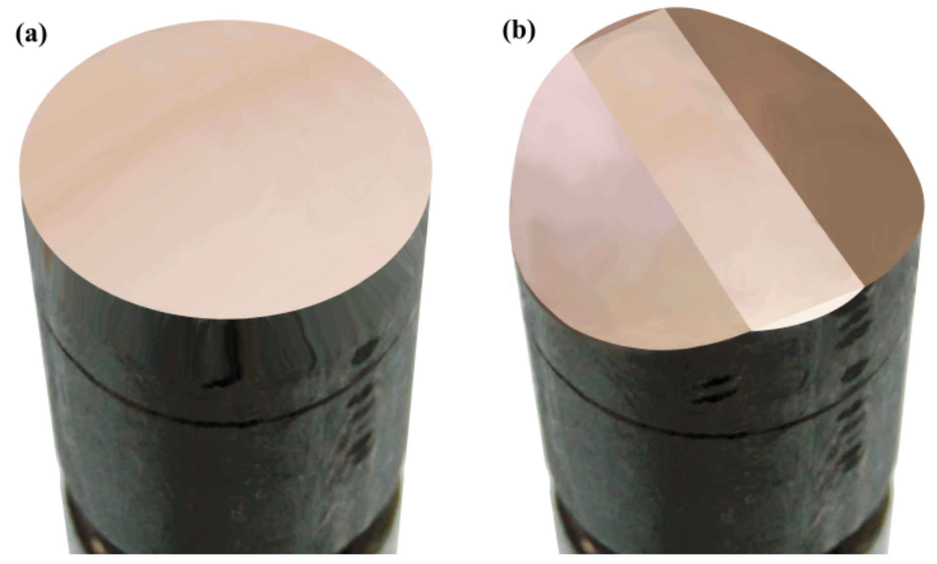
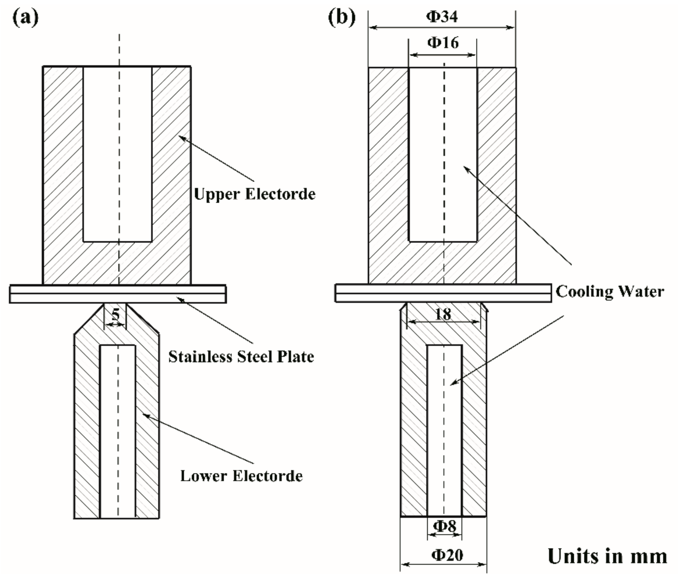
2.1. Experimental Materials and Sample Dimensions

The material used in this study is SUS304 austenitic stainless steel plate commonly used in railway vehicles. The chemical compositions and physical properties are shown in Table 1 and Table 2, respectively.
The dimensions of the stainless steel plate were 70 mm × 40 mm × 0.9 mm. The upper and lower plates with the same thickness and dimensions were welded into lap joints. The rectangular terminal electrode was adopted as a lower electrode. The dimensions of the rectangular terminal surface were 18 mm × 5 mm, embedded with a Ф 8 mm cooling water channel inside of the electrode. The cylindrical planar electrode was adopted as an upper electrode. The diameter of the cylindrical planar electrode was Ф 34 mm, embedded with a Ф 16 mm cooling water channel. Figure 1 shows the cylindrical planar electrode and the rectangular terminal electrode. Figure 2 shows the dimensions of the electrodes and the clamping method with workpieces.

2.2. Welding Parameters

The parameters of RSW on austenitic stainless steel with ordinary circular electrode were taken as a reference to formulate welding parameters of RSW with a rectangular terminal electrode. The welding current was adjusted to ensure that the welding current density was similar than the ordinary circular electrode RSW. The welding pressure was adjusted, considering the increase of the contact area between the electrode and workpieces. Table 3 shows the parameters commonly used of RSW for an ordinary circular electrode on an austenitic stainless steel plate with a thickness of 0.9 mm and the proposed parameters for rectangular terminal electrode RSW with the same material and thickness. According to the parameter ranges shown in Table 3, nine welding current parameters, seven welding time parameters, and five welding pressure parameters, shown in Table 4, were selected and formed the 315 technology parameter sets for rectangular terminal electrode RSW.
As the terminal of electrode is rectangular, the RSW nugget is normally elliptical in shape. Six RSW joints were welded for each parameter set, three of them were transverse cut along the long axis direction of the nugget, and the other three joints were cut vertically along the short axis direction. The cutting methods are shown in Figure 3. The cut workpieces were made into metallographic specimens. The specimens were roughly grinded on the 240 to 1000 mesh sandpapers in turn firstly, and then accurately grinded on the 2000 to 3000 mesh sand papers, and, finally, polished on the rotating wet polishing cloth to obtain a smooth metallographic surfaced. The corrosive solution was prepared with 1 mL nitric acid, 5 mL glycerin, 0.25 g copper chloride, and 20 mL hydrochloric acid. The polished metallographic surface was immersed in the corrosive solution for 4 min, then washed with alcohol and blown dry. The metallographic samples were observed under the Axio Scope A1 metallographic microscope (Zeiss, Germany), so the metallographic photos were taken and the dimensions of nuggets were measured. The dimensions of the long axis and the short axis of the nugget were measured, respectively, and the dimension variations of the nugget under different welding parameters were recorded.

3. Results and Discussion

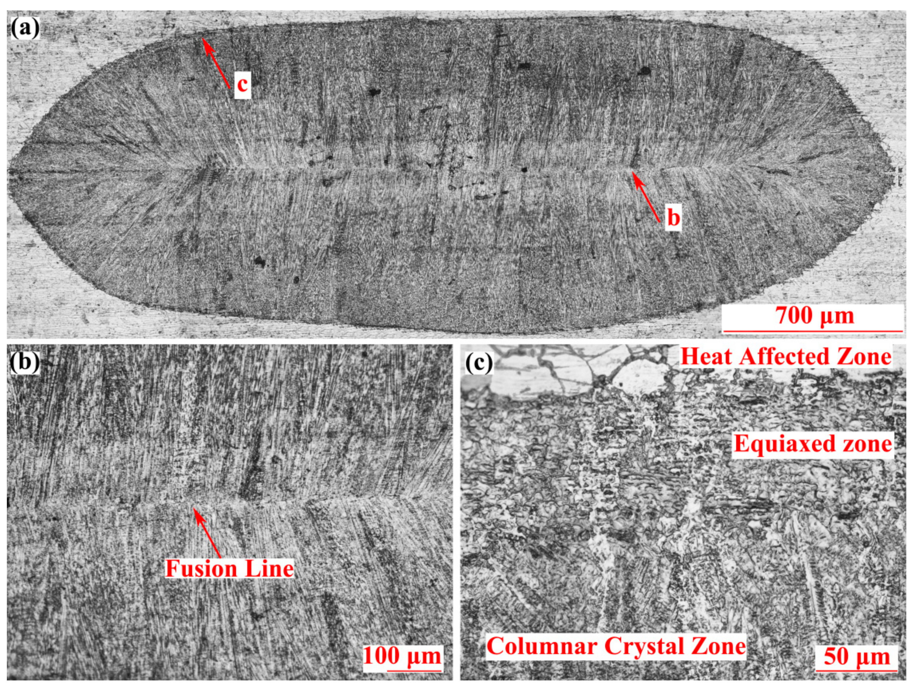
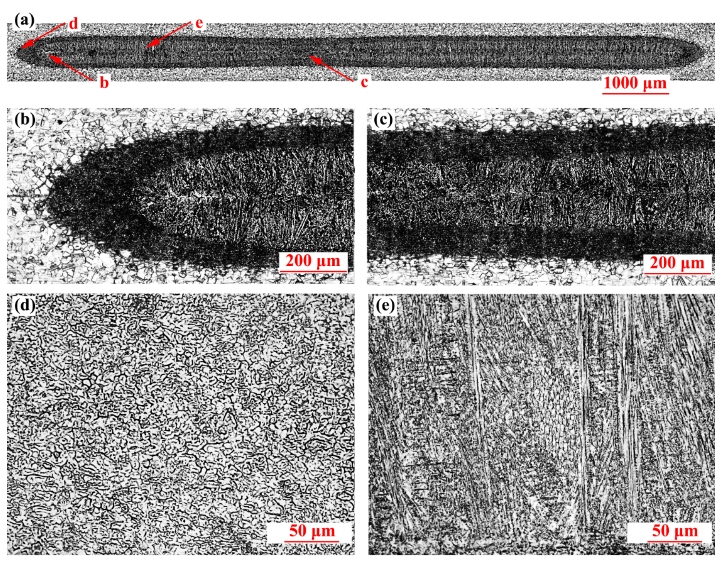
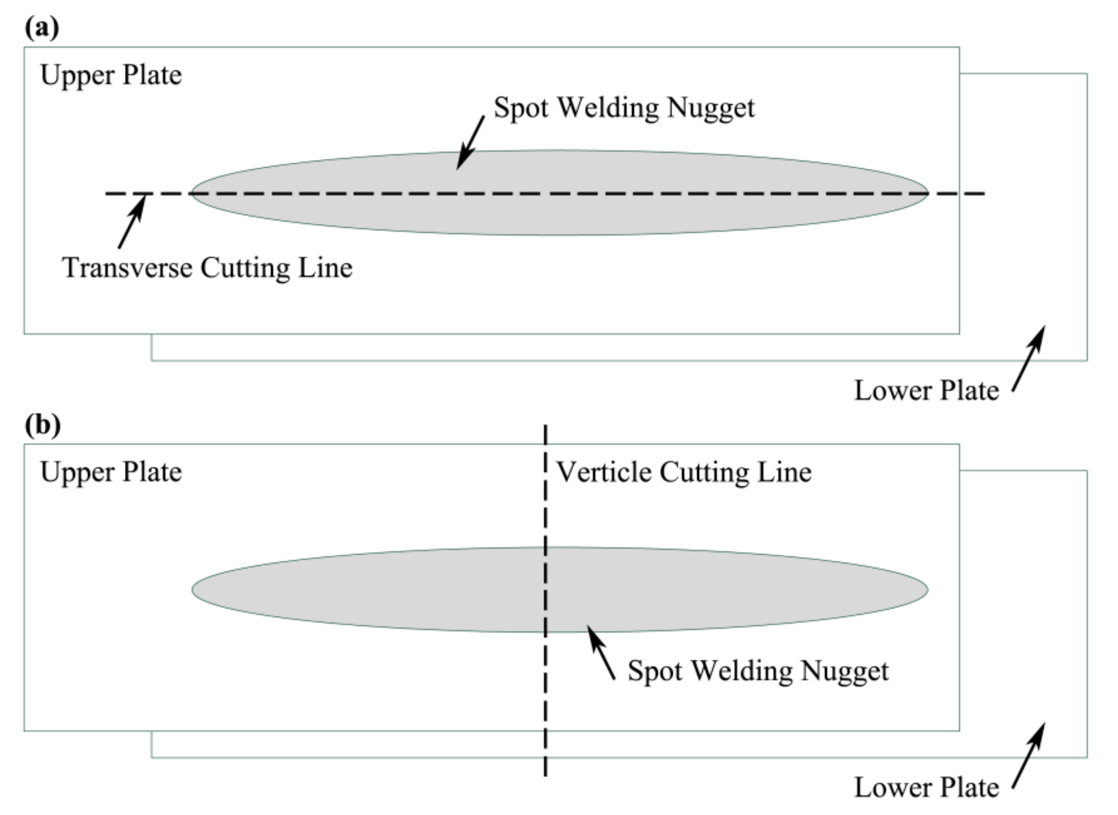
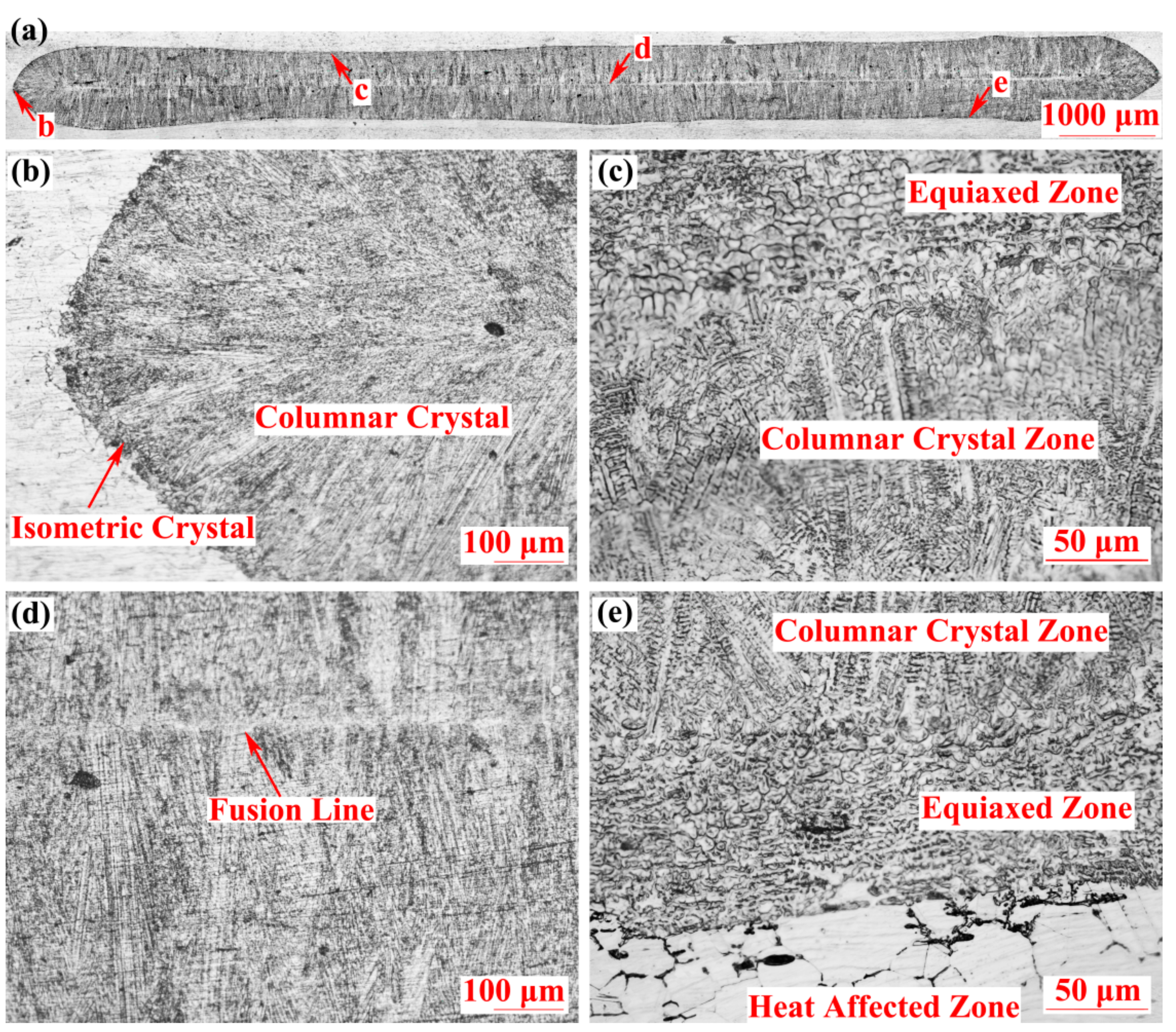
3.1. Metallographic Morphology of the Well-Connected RSW Joints

Figure 4 shows the metallographic morphology of the transverse cutting section of the well-connected RSW joints (welding current: 16.5 kA, welding pressure: 7.5 kN, welding time: 160 ms). As shown in Figure 4a, the length of the nugget along the long axis direction was about 11.8 mm, while the depth of the nugget was about 1 mm, and the nugget depth on the upper and lower steel plate was basically the same. The columnar crystals in the nugget were evenly distributed and regularly shaped, showing that they grew from the edge of the nugget edge to the fusion center until they intersected at the fusion line and formed a solidified nugget, as shown in Figure 4b–d. There was a thin equiaxed zone between the columnar crystals and the base metal as shown in Figure 4c. This was because, during the solidification process, the crystal nucleus formed firstly at the edge of the molten pool due to the lower temperature, and, meanwhile, the crystal nucleus grew, fell off, dissociated, crystallized into small grains near the edge of the molten pool, and formed the equiaxed zone at the edge of the nugget. When the equiaxed zone formed, the heat dissipation in the center of the molten pool needed to go through the equiaxed zone to the base metal. The slow heat dissipation reduced the degree of undercooling and made it easier to form columnar crystals. Besides those, the heat affected zone with coarse grain was distributed uniformly on the base metal edge, as shown in Figure 4e.
The RSW joint with the same welding parameters as the joint shown in Figure 4 was vertically cut along the short axis direction, and the metallographic morphology is shown in Figure 5. The length of the nugget in the short axis direction was about 3.4 mm, and its metallographic morphology and dimensions were similar to that of ordinary circular electrode RSW joint. Consistent with the metallographic morphology of the transverse cutting section, there is a thin equiaxed zone at the edge of the nugget, and the central part is basically composed of coarse columnar crystal.
As shown in the above metallographic photos, by adopting the rectangular terminal electrode, the dimensions of RSW joints in the long axis direction are larger than that in the short axis direction. In order to study the relationship of the dimensions on the long and short directions, the welded joints under different technology parameter sets were cut and the dimensions of the nuggets on the long axis and short axis were measured, respectively. The measurement results are shown in Figure 6. The dimensions of the long axis and short axis of the welded joints are linearly distributed, and the ratio of long/short axis dimensions is approximately 3.6:1, which is equal to the ratio of the long/short side lengths of the rectangular terminal electrode surface.

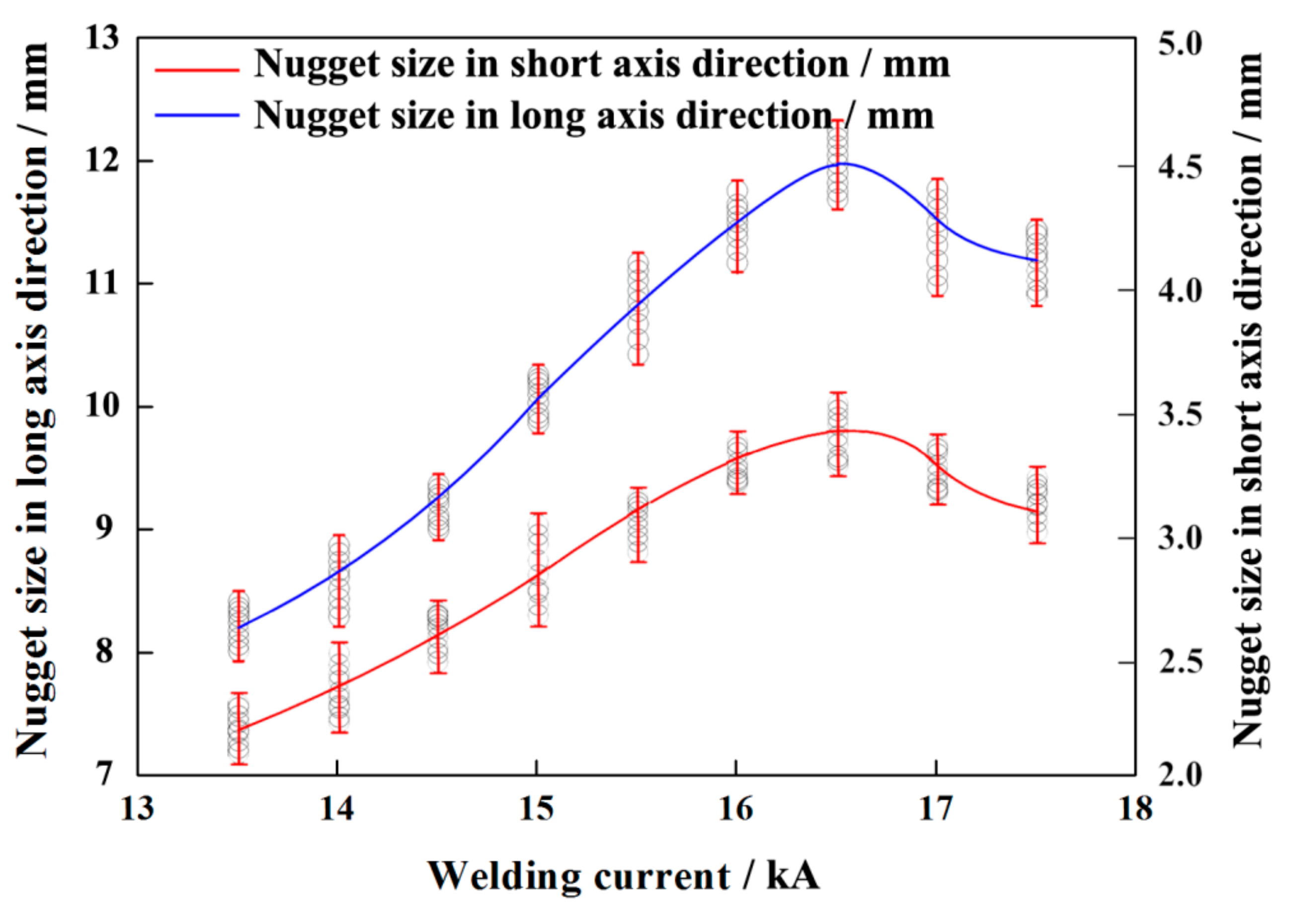
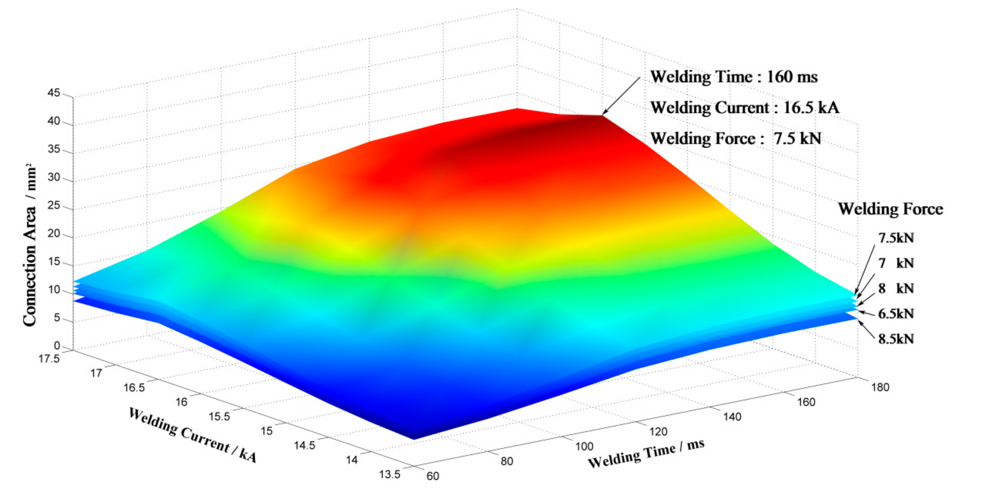
3.2. Influence of Welding Current on the RSW Nuggets

Figure 7 shows the influence of welding current on the nugget dimensions of the long axis direction (the welding time is 160 ms and the welding pressure is 7.5 kN). With the increase in welding current, the nugget dimensions of the long axis direction increased first and then decreased, and the peak value was about 12 mm, when the welding current was 16.5 kA. This is because the heat generation effect during the welding process conforms to Joule’s law.
When the welding current is too small (less than 13.5 kA), the nugget cannot be formed since the heat generation is far less than the heat required to melt the joint. When the welding current increases (greater than 13.5 kA), the heat production in the joint increases rapidly, and the heat accumulates between the base metal, so the upper and lower steel plate are melted to form the nugget. With the further increase in welding current, the heat in the joint accumulates rapidly, which makes the dimensions of the RSW nuggets increase rapidly. When the welding current is more than the critical value (16.5 kA), the heating speed is too fast due to the high welding current. Since the electrode cooling effect is mainly completed through the circulation of the cooling water, the heat generated in the welding joint cannot be quickly exported through the electrode under the condition of the fast heating speed. At this time, the corona bond around the nugget has not yet formed, and the high temperature molten steel extrudes out of the RSW joint and formed splash, resulting in the dimensions of nugget reduced, and shrinkage happens more easily.
Figure 8 shows the metallographic morphology of the transverse cutting section of RSW joints when the welding current is 15 kA. As shown in Figure 8a, the dimension of nugget in the long axis direction was about 10.4 mm, and the nugget depth was about 0.65 mm. There was a wide equiaxed zone at the edge of the RSW joint, as shown in Figure 8b,c. There was a clear boundary between the equiaxed zone and the columnar crystal zone, and the grain size was also different. Figure 8d shows the metallographic morphology of the equiaxed zone, and the dimension of the grain is small. The reason for the wide equiaxed zone is that the heat storage in the molten pool is small due to the small welding current, and the heat dissipation at the edge of the molten pool is fast, resulting in the high degree of supercooling. In the process of crystallization, a large amount of nucleus forms at the edge of the RSW joint, and the nucleus grow up to form isometric crystal. With the formation of the equiaxed zone at the edge of the nugget, the temperature difference between the center and the edge of the molten pool decreases, and uniform columnar crystal can be easily formed, as shown in Figure 8e.
When the welding current changes, there are nugget differences, not only in dimensions, but also in metallographic morphology. Figure 9 shows the metallographic morphology at the transverse cutting section of RSW joints when the welding current ranges from 13.5 kA to 16.5 kA. With the increase in welding current, the dimensions of the long axis direction of the RSW joints gradually increase from 8 mm to 12 mm. When the welding current is large, the metallographic morphology of the RSW joint is mainly composed of regular columnar crystal, as shown in Figure 9a. As the welding current decreases gradually, the heat input of the RSW joint decreases. Therefore, the dimensions on the long axis direction of RSW joints decreases, and, on the other hand, due to the significant change of heat dissipation condition, the equiaxed zone at the edge of the nugget increases gradually, while the columnar crystal zone decreases gradually, as shown in Figure 9b,c. When the welding current decreases to 13.5 kA, there is no columnar crystal in the nugget, but a completely isometric crystal, as shown in Figure 9d. Figure 10 shows the comparison of crystal sizes in the equiaxed zone under different welding currents. When the welding current was 16.5 kA, the crystal size was about 3–5 μm, as shown in Figure 10a. With the decrease in welding current, the crystal size of the equiaxed zone gradually increased to 4–8 µm and 6–12 μm, as shown in Figure 10b,c, respectively. When the welding current is 13.5 kA, the crystal size is about 10–18 μm, as shown in Figure 10d. These results show that with the decrease of welding current, the crystal size of the equiaxed zone increases gradually, which is due to the decrease of heat input and undercooling.

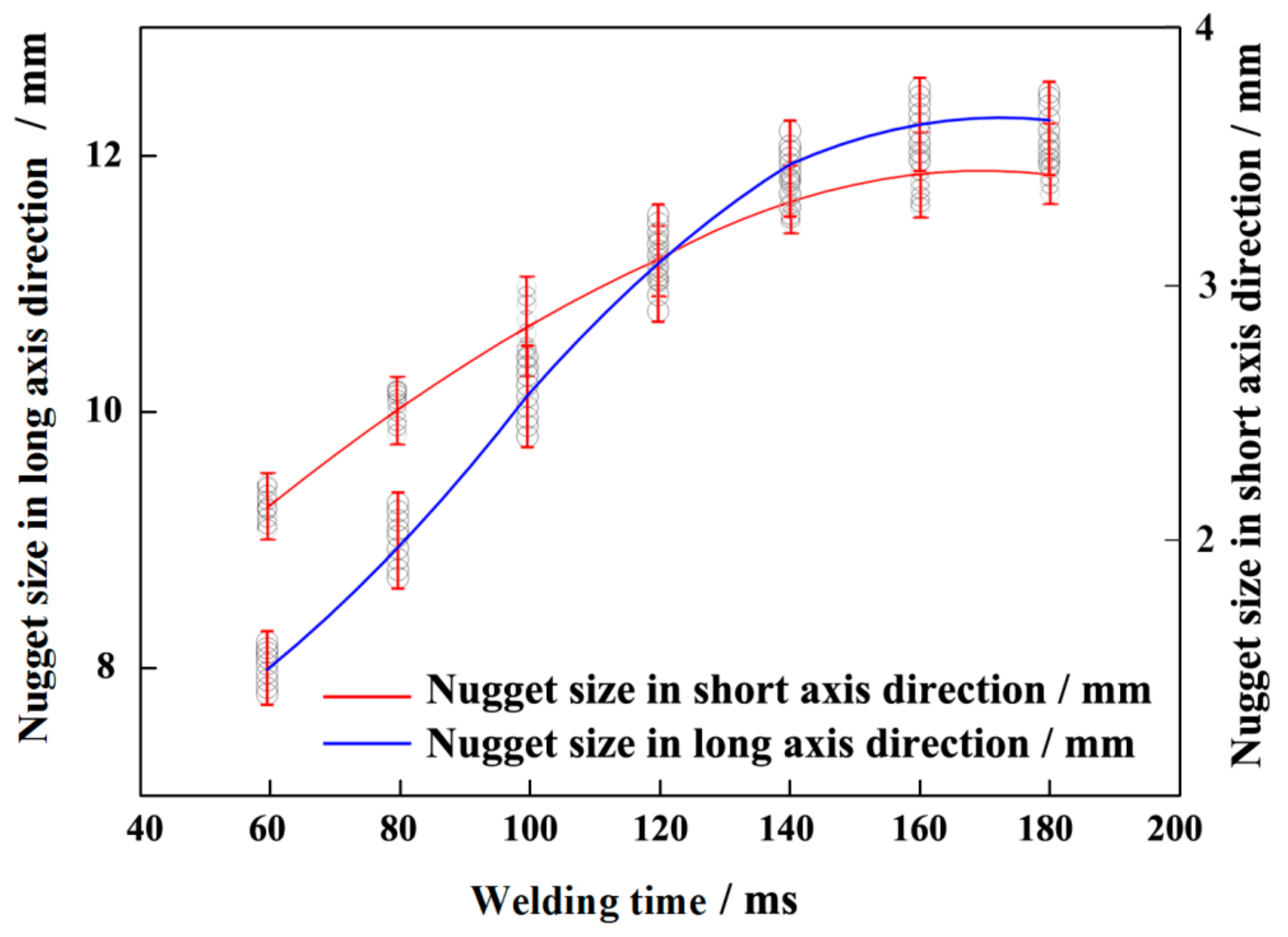
3.3. Influence of Welding Time on the RSW Nuggets

Figure 11 shows the influence of welding time on the nugget dimensions of the long axis direction (the welding current is 16.5 kA and the welding pressure is 7.5 kN). With the increase in welding time, the nugget dimensions on the long axis direction increased rapidly. When the welding time reached a certain value, the nugget dimensions gradually stabilized. This is because, during the welding process, the nugget is generally produced in the center of the electrode, and the dimensions of nuggets are affected by both heat generation and heat dissipation. When the welding time is short (less than 60 ms), due to the low heat production, the accumulated heat is not enough to melt the base metal to form nugget, and only a little heating trace is formed on the surface of the base metal. With the increase in welding time, the heat production in the nugget increases gradually and the accumulated heat will directly lead to the increase of the nugget dimensions. When the welding time increases to a certain value, a large amount of heat is exported through the electrode and the heat production and heat dissipation both increase rapidly, so the nugget dimensions increase to the critical value. When the welding time exceeded the critical value (160 ms ), the welding time was long enough that a large amount of heat can be exported through the electrode, so the heat production and heat dissipation in the nugget are basically in a balance. Therefore, with the increase in welding time, the increase in nugget dimensions was not obvious, only the indentation on the surface of base metal was deepened, and generally no splash happened.

3.4. Influence of Welding Pressure on the RSW Nuggets

Figure 12 shows the influence of welding pressure on the nugget dimensions of the long axis direction (the welding current is 16.5 kA and the welding time is 160 ms). With the increase in electrode pressure from 6.5 kN to 7.5 kN, the nugget dimensions in the long axis direction increased with the increase in electrode pressure, and the largest nugget dimension was 12.2 mm. This is because with the increase of welding pressure, the bonding surface between the base metal plates becomes larger, and the welding current is evenly distributed on the bonding surface, forming a larger nugget. When the welding pressure was larger than 7.5 kN, the nugget dimensions decreased with the increase of welding pressure. This is because when the bonding surface between the base metal plates increases to a certain value, the heat production decreases due to decreases in the welding current density. Meanwhile, as the bonding area increases, the heat dissipation of RSW joints through the electrode increases too. Therefore, it is easier to obtain the joint with a small nugget and large heat affected zone.
It is worth noting that when the welding pressure is too small, it was easier to produce two adjacent nuggets with small dimensions, as shown in Figure 13. Generally, when the welding pressure is too small, due to the deformation of the steel plates, the contact in the central position is better than the edge, so the nugget is normally formed at the central position of the electrode. However, due to the dimension differences of the long side and the short side of the rectangular terminal electrode, when the welding pressure is insufficient, the surface roughness of electrode and the workpiece may lead to the better contact on the edge than at the central position. Therefore, the welding current was more concentrated at the edge and the shunt effect was caused on both sides of the electrode, forming the adjacent double nuggets, as shown in Figure 13a. Meanwhile, due to the shunt effect of welding current and the increase in contact area, the heat generation was small and the heat dissipation was fast, so that the temperature gradient inside and outside of the nugget was small, forming the isometric crystal, as shown in Figure 13b. In the middle position of the adjacent double nugget, due to the less contact between steel plates, the current density is small. The small heat generation makes the area between the adjacent double nuggets appear as a heat affected zone with coarse grain, and the heat affected zone shows comet-like morphology on both sides, as shown in Figure 13c.
Figure 14 shows the comprehensive influence of those welding parameters on the connection area. As shown in the figure, when the welding time was 160 ms, the welding current was 16.5 kA, the welding pressure was 7.5 kN, the joint connection area reached the maximum value of 31.2 mm2.

4. Conclusions

The RSW process technology with rectangular terminal electrode was studied, and the connection states of RSW joints under different process parameters were analyzed. The conclusions are as below:
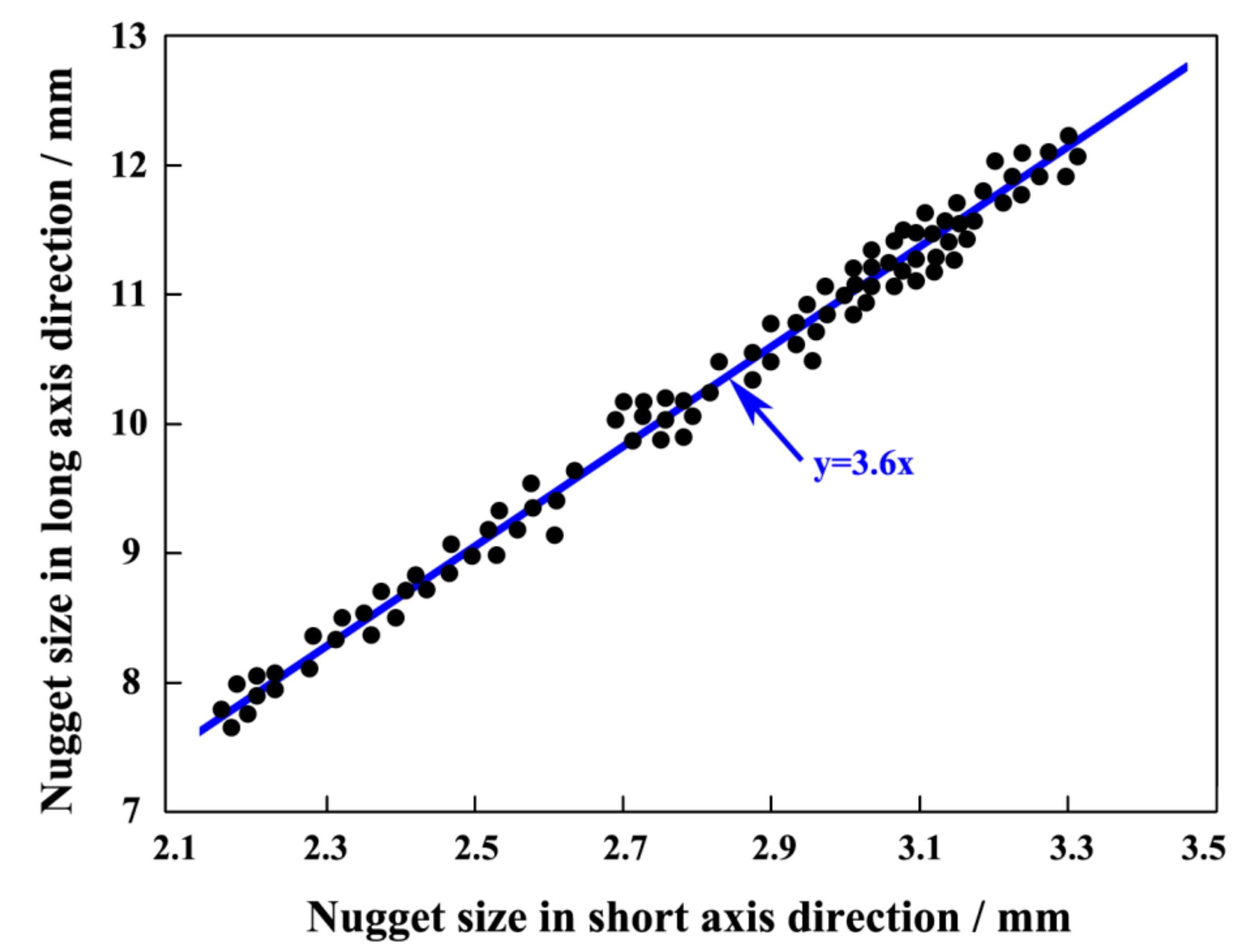
  • Elliptical welding joints can be obtained on stainless steel plates by RSW with rectangular terminal electrode. There is a proportional relation between the nugget’s dimensions on the long axis and the short axis, and the nugget’s dimension ratio of the long and short axis is generally close to that of the long and short sides of the rectangular terminal electrode.
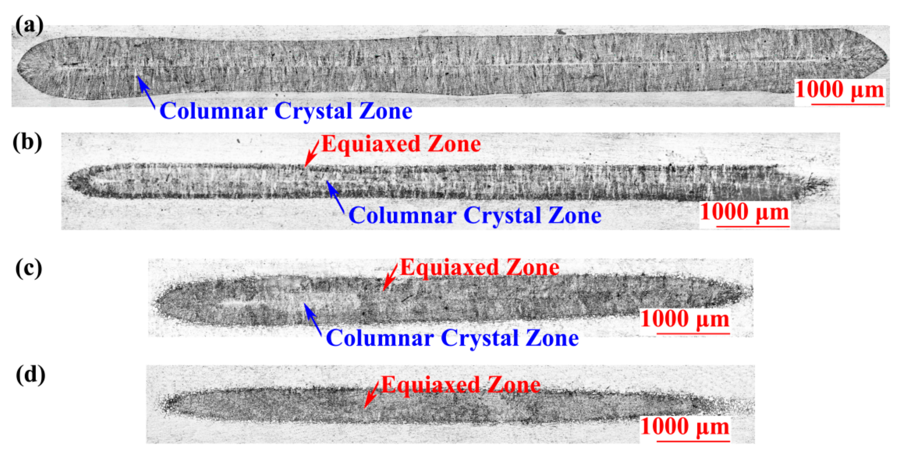
  • The electrode terminal area can be used as an input to roughly estimate welding current density and the welding current range can be settled according to this. With the welding current increase, the RSW nugget’s dimensions of the long axis increase first and then decrease. When the nugget dimension reaches the peak value, the nuggets are mostly composed of regular columnar crystal and have a typical spot welded joint morphology. When the welding current decreases, the nugget dimensions decrease and the width of the equiaxed zone increases gradually. When the welding current is too small, the columnar crystal zone at the central of the nugget disappears, and the nugget is completely composed of isometric crystals.
  • With the increase in welding time, the RSW nuggets dimensions increase first and then remain steady. The long welding time generally does not cause splash during the welding process.
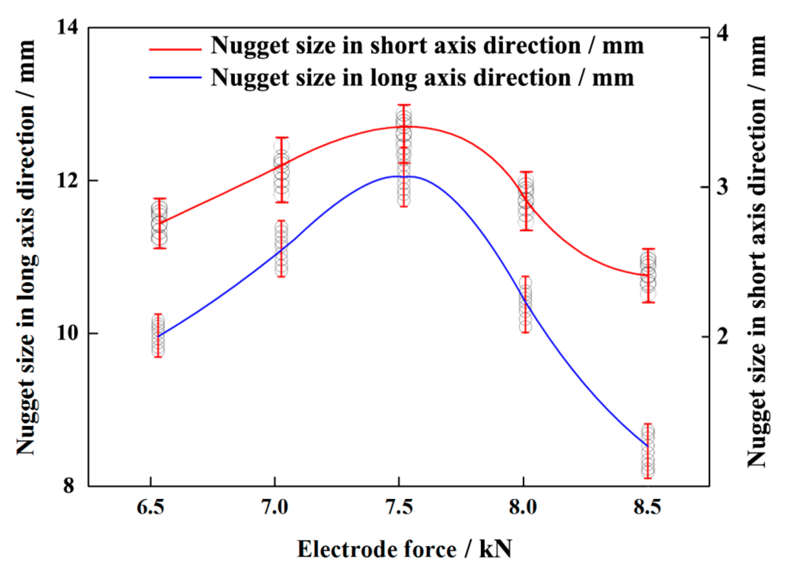
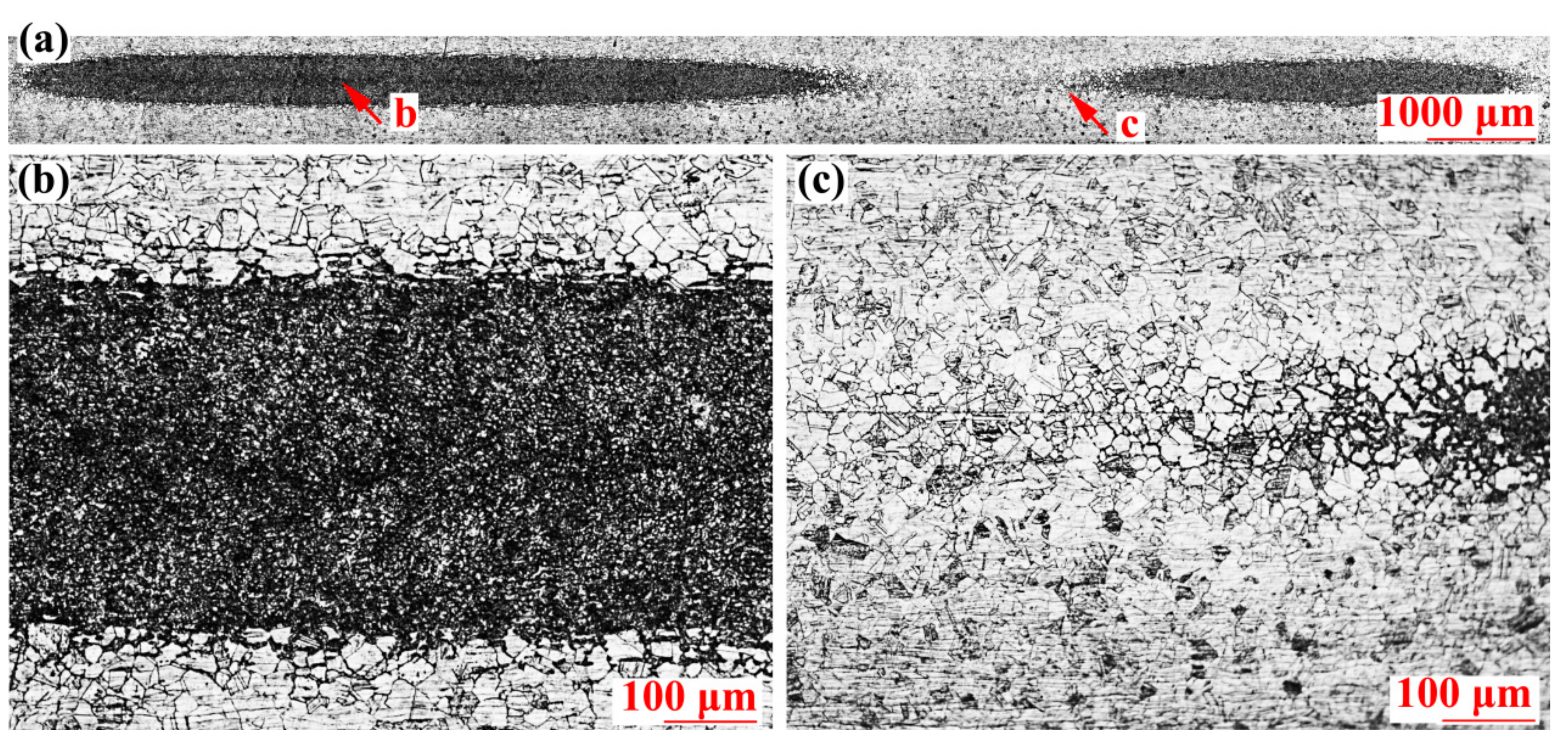
  • The electrode terminal area can be used as an input to roughly estimate welding pressure range. With the welding pressure increase, the RSW nuggets dimensions of long axis increase first and then decrease. When the welding pressure is too high, it is easy to produce welding joints with small nugget dimensions and large heat affected zone. When the welding pressure is too small, it is easy to produce a unique joint with two adjacent nuggets.
According to this research, the rectangular terminal electrode can be adopted to effectively improve the connection strength of RSW. When choosing the electrode terminal geometry, rectangular is not the only option. However, compared with other shapes, such as round, oval, and diamond, rectangular can maximize the connection areas with minimum RSW joints distance allowed by shunt. Therefore, the rectangular electrode is the best choice to increase the connection strength of RSW in the practical application. Of course, compared with the traditional circular electrode, manufacturing cost using the rectangular terminal electrode will be increased, so other factors, such as cost, strength, and production efficiency, should be taken into consideration when adopting the rectangular electrode.

Author Contributions

Conceptualization, X.Z.; Data curation, X.Z., L.W. and C.W.; Resources, L.W., G.X. and C.W.; Writing—original draft, X.Z.; Writing—review & editing, G.X. and C.W.

Funding

This research was funded by: The Industrial Technology Research and Development Project of Jilin Provincial Development and Reform Commission, grant number 2019C039-6; The 13th Five-year Plan Science and Technology Project of Jilin Province, grant number JJKH20181175KJ; The Talent Introduction Project of Changchun Normal University, grant number Changchun Normal University RC [2016] No.004.

Conflicts of Interest

The authors declare no conflict of interest.

References

  1. Ramazani, A.; Mukherjee, K.; Abdurakhmanov, A.; Abbasi, M.; Prahl, U. Characterization of microstructure and mechanical properties of resistance spot welded DP600 steel. Metals 2015, 5, 1704–1716. [Google Scholar] [CrossRef]
  2. Bhole, S.D.; Ma, C.; Khan, M.S.; Chen, D.L. A study of spot welding of advanced high strength steels for automotive applications. J. Iron Steel Res. Int. 2011, 18, 724–729. [Google Scholar]
  3. Bina, M.H.; Jamali, M.; Shamanian, M.; Sabet, H. Investigation on the resistance spot-welded austenitic/ferritic stainless steel. Int. J. Adv. Manuf. Tech. 2014, 75, 1371–1379. [Google Scholar] [CrossRef]
  4. Zhang, H.; Hou, Y.; Zhang, J.; Wang, F. A new method for nondestructive quality evaluation of the resistance spot welding based on the radar chart method and the decision tree classifier. Int. J. Adv. Manuf. Technol. 2015, 78, 841–851. [Google Scholar] [CrossRef]
  5. Jou, M. Real time monitoring weld quality of resistance spot welding for the fabrication of sheet metal assemblies. J. Mater. Process. Technol. 2003, 132, 102–113. [Google Scholar] [CrossRef]
  6. Qiao, Z.; Li, H.; Li, L.; Ran, X.; Feng, L. Microstructure and properties of spot welded joints of hot-stamped ultra-high strength steel used for automotive body structures. Metals 2019, 9, 285. [Google Scholar] [CrossRef]
  7. Zhang, H.; Wang, F.; Xi, T.; Zhao, J.; Wang, L.; Gao, W. A novel quality evaluation method for resistance spot welding based on the electrode displacement signal and the Chernoff faces technique. Mechan. Syst. Signal Process. 2015, 62–63, 431–443. [Google Scholar] [CrossRef]
  8. Kahraman, N. The influence of welding parameters on the joint strength of resistance spot welded titanium sheets. Mater. Des. 2007, 28, 420–427. [Google Scholar] [CrossRef]
  9. Zou, J.; Zhao, Q.; Chen, Z. Surface modified long-life electrode for resistance spot welding of Zn-coated steel. J. Mater. Process. Tech. 2009, 209, 4141–4146. [Google Scholar] [CrossRef]
  10. Saeed, A.M.; Zuhailawati, H.; Ismail, A.B.; Samad, Z.; Ariga, T. Weldability of titanium and nickel with alloy filler addition and different electrodes tip shapes by using micro spot brazing method. Int. J. Adv. Manuf. Technol. 2014, 73, 591–599. [Google Scholar] [CrossRef]
  11. Qiu, R.; Zhang, Z.; Zhang, K.; Shi, H.; Ding, G. Influence of welding parameters on the tensile shear strength of aluminum alloy joint welded by resistance spot welding. J. Mater. Eng. Perform. 2011, 20, 355–358. [Google Scholar] [CrossRef]
  12. Jia, Q.; Liu, L.; Guo, W.; Peng, Y.; Zou, G.; Tian, Z.; Zhou, Y.N. Microstructure and tensile-shear properties of resistance spot-welded medium Mn steel. Metals 2018, 8, 48. [Google Scholar] [CrossRef]
  13. Tutar, M.; Aydin, H.; Bayram, A. Effect of weld current on the microstructure and mechanical properties of a resistance spot-welded TWIP steel sheet. Metals 2017, 7, 519. [Google Scholar] [CrossRef]
  14. Fan, Q.; Xu, G.; Wang, T. The influence of electrode tip radius on dynamic resistance in spot welding. Int. J. Adv. Manuf. 2018, 95, 3899–3904. [Google Scholar] [CrossRef]
  15. Liang, C.P.; Liu, X.H.; Bai, Y.W. Effect of electrode force change on spot weld quality of AHSS using servo gun. Adv. Mater. Res. 2011, 189–193, 3359–3363. [Google Scholar] [CrossRef]
  16. Podrzaj, P.; Polajnar, I.; Diaci, J.; Kariz, Z. Expulsion detection system for resistance spot welding based on a neural network. Meas. Sci. Technol. 2004, 15, 592–598. [Google Scholar] [CrossRef]
  17. Cho, Y.; Rhee, S. New technology for measuring dynamic resistance and estimating strength in resistance spot welding. Meas. Sci. Technol. 2000, 11, 1173–1178. [Google Scholar] [CrossRef]
  18. Banerjee, P.; Sarkar, R.; Pal, T.K.; Shome, M. Effect of nugget size and notch geometry on the high cycle fatigue performance of resistance spot welded DP590 steel sheets. J. Mater. Process. Technol. 2016, 238, 226–243. [Google Scholar] [CrossRef]
  19. Zhou, K.; Cai, L. Online nugget diameter control system for resistance spot welding. Int. J. Adv. Manuf. 2013, 68, 2571–2588. [Google Scholar] [CrossRef]
  20. Peng, J.; Fukumoto, S.; Brown, L.; Zhou, N. Image analysis of electrode degradation in resistance spot welding of aluminium. Sci. Technol. Weld. Join. 2004, 9, 331s–336s. [Google Scholar] [CrossRef]
  21. Varbai, B.; Sommer, C.; Szabó, M.; Tóth, T.; Májlinger, K. Shear tension strength of resistant spot welded ultra high strength steels. Thin Wall Struct. 2019, 142, 64–73. [Google Scholar] [CrossRef]
  22. Zhang, X.; Xu, G.; Jing, W.; Wang, C. The research for resistance spot welding with rectangular electrode. In Proceedings of the International Conference on Mechatronics and Automation, Changchun, China, 9–12 August 2009. [Google Scholar]
Figure 1. Electrodes: (a) the cylindrical planar electrode and (b) the rectangular terminal electrode.
Metals 09 00659 g001
Figure 2. Dimensions of electrodes and the clamping method with workpieces: (a) the front view and (b) the side view.
Metals 09 00659 g002
Figure 3. Cutting methods for metallographic samples of RSW joint: (a) transverse cutting and (b) vertical cutting.
Metals 09 00659 g003
Figure 4. Metallographic morphology of nugget on the transverse cutting section: (a) overall perspective, (b) morphology on the nugget end, (c) morphology on the nugget upper side, (d) morphology on the fusion zone, and (e) morphology on the nugget lower side.
Metals 09 00659 g004
Figure 5. Metallographic morphology of nugget on the vertical cutting section: (a) overall perspective, (b) morphology of fusion zone, and (c) morphology on the nugget lower side.
Metals 09 00659 g005
Figure 6. Dimension distributions of the long axis and short axis of welded joints.
Metals 09 00659 g006
Figure 7. Influence of welding current on the dimensions of nuggets.
Metals 09 00659 g007
Figure 8. Metallographic morphology of nugget on the transverse cutting section (The welding current is 15 kA): (a) overall perspective; (b) morphology on the nugget left side; (c) morphology on the nugget middle side; (d) morphology on the equiaxed zone and (e) morphology on the columnar crystal zone.
Metals 09 00659 g008
Figure 9. Metallographic morphology of RSW joints at different welding currents. The welding currents are (a) 16.5 kA, (b) 15 kA, (c) 14 kA, and (d) 13.5 kA.
Metals 09 00659 g009
Figure 10. Comparison of crystal sizes in the equiaxed zone under different welding currents. The welding currents are (a) 16.5 kA, (b) 15 kA, (c) 14 kA, and (d) 13.5 kA.
Metals 09 00659 g010
Figure 11. Influence of welding time on the dimensions of nuggets.
Metals 09 00659 g011
Figure 12. Influence of welding pressure on the dimensions of nuggets.
Metals 09 00659 g012
Figure 13. Metallographic morphology of nugget on the (The welding pressure is 6.5 kN): (a) overall perspective, (b) morphology on the nugget left side, and (c) morphology on the heat affected zone in the center.
Metals 09 00659 g013
Figure 14. The comprehensive influence of the welding parameters on the connection area.
Metals 09 00659 g014
Table 1. Chemical compositions of SUS304 stainless steel plate (wt%).
CSiMnPSNiCrN
≤0.08≤1.00≤2.50≤0.035≤0.0307.00–10.50018.00–20.000.01–0.25
Table 2. Mechanical properties of SUS304 stainless steel plate.
Hardness (HV)Yield Strength (N/mm2)Tensile Strength (N/mm2)Elongation (%)
>169>275>550>35
Table 3. Resistance spot welding (RSW) parameters for 0.9 mm thickness stainless steel plate.
Type of ElectrodeDimensions of Electrode (mm)Welding Current (kA)Welding Time (ms)Welding Pressure (kN)
Ordinary circular electrodeФ 5 (upper) + Ф 34 (lower)5.5–6.5100–1603.0–4.0
Rectangular terminal electrode5 × 18 (upper) + Ф 34 (lower)13.5–17.560–1806.5–8.5
Table 4. Adopted parameter sets for the rectangular terminal electrode.
Welding Current (kA)Welding Time (ms)Welding Pressure (kN)
13.5606.5
14807
14.51007.5
151208
15.51408.5
16160
16.5180
17
17.5

