Abstract
Material reductions, weight savings, design optimisation, and a reduction in the environmental impact can be achieved by improving the performance of near-net shape (NNS) titanium alloy components. The method demonstrated in this paper is to use a solid-state approach, which includes diffusion bonding discrete layers of dissimilar titanium alloy powders (CP-Ti, Ti-6Al-4V and Ti-5Al-5Mo-5V-3Cr) using field-assisted sintering technology (FAST), followed by subsequent forging steps. This article demonstrates the hybrid process route, firstly through small-scale uni-axial compression tests and secondly through closed-die forging of dissimilar titanium alloy FAST preforms into an NNS (near-net shape) component. In order to characterise and simulate the underlying forging behaviour of dissimilar alloy combinations, uni-axial compression tests of FAST cylindrical samples provided flow stress behaviour and the effect of differing alloy volume fractions on the resistance to deformation and hot working behaviour. Despite the mismatch in the magnitude of flow stress between alloys, excellent structural bond integrity is maintained throughout. This is also reflected in the comparatively uncontrolled closed-die forging of the NNS demonstrator components. Microstructural analysis across the dissimilar diffusion bond line was undertaken in the components and finite element modelling software reliably predicts the strain distribution and bond line flow behaviour during the multi-step forging process.
1. Introduction
Titanium alloys are desirable to use in high-performance applications due to a combination of a high strength-to-weight ratio, excellent corrosion resistance, and fatigue performance. Consequently, titanium alloys are a key material for the aerospace industry in components such as gas turbine compressor parts, engine pylons, and landing gear forgings. Today, small to medium aerospace high-strength components, such as hook, pylon, and strut profiles are machined from a single titanium alloy forging.
Optimising the mechanical properties of metallic components benefits performance, by reducing cost and weight through optimal design and minimising the environmental impact. A conventional approach for material property optimisation is to produce tailored microstructures, for example, the dual grain size distribution in a nickel superalloy aero-engine gas turbine disk. Hot isostatic pressing (HIPing), extrusion, and forging processes of nickel superalloy powder feedstock can produce fine-grain lamellar microstructures in the disk bore for low-cycle fatigue (LCF) resistance and coarse-grained microstructures in the disk rim for optimised creep resistance.
Although dissimilar titanium alloys have been demonstrated that they can be joined through linear friction welding in blisk (bladed rotor disc) prototype parts [1,2], such solid-state joining of dissimilar titanium alloys has yet to be implemented into production parts. Yet in the future, optimised performance could be achieved in titanium components if different alloys and tailored microstructures were targeted for different sub-component regions. In the case of a gas turbine engine blisk for example, circumferential blades produced from a creep resistant, near α titanium alloy could be bonded to a rotor disk produced from a high strength, low-cycle fatigue resistant near β or α+β titanium alloy.
A new hybrid powder metallurgy approach combining accelerated sintering with hot forging, could provide designers with the option to engineer future components with sections containing dissimilar titanium alloys, thus integrating controlled changes in properties across the component. A solid-state powder processing method known as field assisted sintering technology (FAST) or spark plasma sintering (SPS) is emerging as a flexible powder consolidated route for titanium alloys [3,4,5,6,7,8,9,10,11,12,13,14,15]. When compared to conventional powder processing and sintering methods, FAST is advantageous due to an electrical current, which has been shown to provide faster heating rates and consolidation compared to conventional sintering [16,17]. FAST has been demonstrated to be an effective sintering route for complex shapes, most notably a novel deformable interface approach produced fully dense CoNiCrAlY turbine blades [18]. Furthermore, FAST-forge [5] and FAST-DB [19] processing routes have been developed, primarily to provide an alternative route to produce titanium components from particulate feedstocks. The first step of FAST-forge is the consolidation of the titanium feedstock into an optimised forging preform using FAST. The subsequent step produces a near-net shape (NNS) component by closed-die forging to refine the as-FAST microstructure. Hot forging is beneficial in titanium alloy components not only to provide a NNS, but to induce flow lines into the product to enhance strength and breakdown the α + β structural unit size.
In terms of bonding dissimilar alloys, solid-state methods are preferred over fusion joining methods, which are subject to solidification issues such as chemical segregation. Recently, FAST-DB has demonstrated the ability to diffusion bond dissimilar titanium alloy gas atomised powders in a simple cylindrical mould using the FAST process [19]. The bonds exhibited excellent structural integrity during tensile testing with no cracks or porosity evident at the bond line interface. Furthermore, the prior β grains at the bond interface had functionally graded chemistries with respect to the dissimilar alloys diffusion bonded by FAST.
In this paper, dissimilar titanium alloys bonded through FAST were characterised and simulated through subsequent hot closed-die forging stages, in order to demonstrate a robust hybrid processing approach for next generation titanium components. Firstly, small-scale FAST-DB compression samples consisting of Ti-6Al-4V (Ti-6-4) and commercially pure titanium (CP-Ti) alloys were deformed using controlled uni-axial compression testing to understand the deformation characteristics. Additionally, for the first time, finite element (FE) software DEFORM 3D has been validated as a method for modelling the controlled deformation of FAST-DB samples to determine the bond interface evolution and strain profiles. Secondly, a semi-complex NNS eye-bolt component was produced using the FAST-DB processing route with subsequent closed-die forging steps. The microstructural evolution of two FAST-DB alloy combinations containing Ti-6-4 bonded with commercially pure titanium and Ti-5Al-5Mo-5V-3Cr (Ti-5553) bonded with Ti-6-4 were characterised post forging. The alloys Ti-6-4 and Ti-5553 were selected for the large-scale NNS forgings due to their increasing usage in the aerospace sector, making them ideal alloys to demonstrate the FAST-forge technology on dissimilar alloys.
2. Materials and Methods
2.1. Materials
The Ti-6-4 and CP-Ti powders were both supplied by Phelly Materials Inc., Upper Saddle River, NJ, USA. They were produced via the hydride-dehydride (HDH) method and consequently have an angular morphology. The Ti-6-4 powder chemistry achieved ASTM B348-11 Grade 5 standard and CP-Ti powder chemistry achieved Grade 1 standard. The Ti-5553 powder was gas atomised (GA) by TLS Technik Spezialpulver from a forged billet and, therefore, the powder had a spherical morphology. The particle size distribution (PSD) of both powders are shown in Figure 1a, and the morphology of CP-Ti, Ti-6-4, and Ti-5553 are shown in Figure 1b–d, respectively.
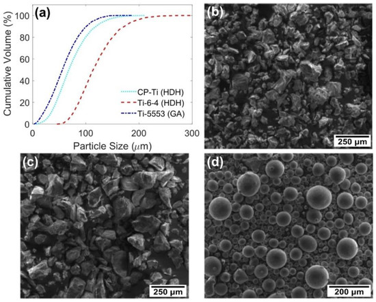
Figure 1.
(a) Graph showing the PSD of each powder; (b) corresponding secondary electron (SE) micrograph of the CP-Ti HDH powder; (c) corresponding SE micrograph of the Ti-6-4 HDH powder; and (d) the corresponding SE micrograph of the Ti-5553 GA powder.
2.2. Field Assisted Sintering
The large-scale FAST billet was processed at Kennametal Ltd. in Newport, Ghent, UK using an FCT Systeme GmbH Type HP D 250 spark plasma sintering furnace with a 250 mm graphite ring mould. Details of the full assembly are shown in detail in Figure 2.
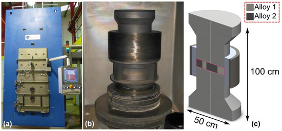
Figure 2.
FAST-DB processing at the Kennametal Ltd. UK facility showing photographs of; (a) the FCT Systeme FAST processing machine; (b) the 250 mm inner diameter assembly consisting of graphite tooling and an outer woven carbon fibre jacket; and (c) the sliced CAD model of the aforementioned assembly showing the division of powders and the pyrometer hole passing through the tooling.
The photographs in Figure 3 show the stages of the manual lay-up of dissimilar titanium alloy powders prior to large-scale FAST processing. To reduce contamination, Ti-6-4 sheet acts as a temporary divider between dissimilar alloy powders during the manual lay-up. A dwell temperature of 1200 °C was used, with a dwell time of 60 mins and a pressure of 35 MPa (1720 kN). The chamber was then evacuated to approximately 2 × 10⁻³ bar and pulsed current was applied through the electrodes to begin heating. Due to the size of the specimen, a slow heating rate of 25 °C/min was required, and the average cooling rate in the water-cooled vacuum chamber was 4 °C/min. Graphite foil was lined on the inside of the mould, as well as on the punch surfaces in contact with the powder, to prevent powder from consolidating to the graphite tooling and to aid sample extraction. The processing chamber was held under vacuum for the entire duration of the process to reduce oxygen pickup. The temperature control was regulated using a vertical pyrometer, which measured the temperature 21 mm above the powder surface within the graphite tooling. To reduce heat loss via radiation, a woven carbon fibre jacket housed the assembly.
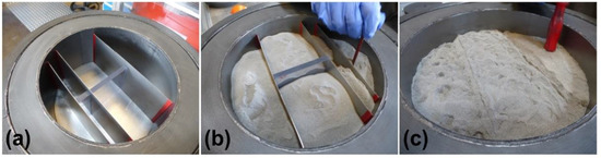
Figure 3.
Photographs of the large-scale manual powder layup at Kennametal Ltd. UK, showing; (a) titanium sheet and Perspex dividers in the 250 mm diameter mould; (b) dissimilar powders filled in the separate sections with agitation of powder using a brush; and (c) flattening of powder after the dividers have been removed.
2.3. Hot Compression Testing and Determination of Flow Stress
To develop an understanding of the upset hot forging of FAST-DB dissimilar titanium alloy samples, the rheological behaviour of the single alloy constituents were first measured to provide flow stress data for the FE model. CP-Ti samples were tested at temperatures of 800, 900, and 950 °C and at constant strain rates of 0.1, 1, and 10 s−1. Ti-6-4 samples were tested at temperatures of 850, 950, and 1050 °C and at constant strain rates of 0.1, 1, and 10 s−1.
The large FAST-DB billet was used to machine nine compression cylinders at the bond interfaces which contained a varying volume fraction of Ti-6-4 and CP-Ti. The cylinders were 15 mm height and 10 mm diameter providing a height to diameter ratio of 1.5:1, as recommended by Roebuck et al. [20]. Before deformation, the bond line at the upper and lower surface of each cylinder was determined. It was assumed the bond line followed a linear path between the two surfaces. A 1.1 mm diameter thermocouple hole was drilled into the centre of each sample from the side, where a 1 mm diameter N-type thermocouple was inserted to achieve close temperature control during hot compressions.
A Servotest Testing Systems Ltd (Egham, UK) thermomechanical compression machine was used to test the samples using strain rate controlled compression. FAST-DB samples were tested at temperatures of 850, 900, and 950 °C at constant strain rates of 0.1, 1, and 10 s−1. Each sample was sprayed with boron nitride lubricant on the upper and lower surfaces contacting the dies to stop adhesion and reduce friction. The test regime included heating to the test temperature at 4 °C/s, using a fast-thermal treatment unit (FTTU), followed by a dwell period of 2 min to ensure temperature homogeneity throughout the sample. The sample was moved into the furnace using robot controlled gripper arms, compressed and quenched with water to suppress any further changes in microstructure. During testing a data logger was used to record time, temperature, load, displacement, and platen velocity. The samples were compressed to half height to achieve a nominal strain of ~0.69.
The true stress data was friction corrected, by applying a shear friction factor to account for the characteristic barreling of the TMC sample, and adjusted for machine compliance during compression. An origin correction was also applied to account for elastic deformation when necessary. The rheology data obtained from constituent Ti-6-4 and CP-Ti compression tests were used in the FE material models. The data was inputted using a tabular format at three temperatures and strain rates, whereby the FE software interpolates between the data points.
2.4. Near-Net Shape, Closed-Die Forging
Forging preforms of dimensions 22 mm diameter by 160 mm length were electro-discharge machined from the 250 mm diameter, 35 mm thick FAST billet. The forging preforms were extracted from the FAST billet with the diffusion bond running along the preform length at the centreline. The eye-bolt demonstrator components were closed-die forged at W.H. Tildesley Ltd., Wolverhampton, UK using a Massey 1.1 MSC drop hammer forge with foot pedal control and 11 kJ blow energy, as shown in Figure 4a. The semi-complex eye-bolt geometry was selected in order to generate a large range of strains across the bond interface. Figure 4b shows a photograph of a machined FAST-DB preform laid on top of the eye-bolt lower die impression. During the forging operations, the stamper was instructed to use as many hammer blows as required to fill the dies. The No. 5 Electem, Ni-Cr-Mo die steel dies are constantly gas heated between 80 and 90 °C throughout the forging process to reduce the die chilling effect.
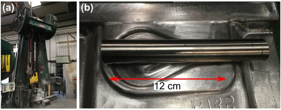
Figure 4.
(a) Photograph of the Massey 1.1 MSC drop hammer forge used in forging trials at W.H. Tildesley Ltd; (b) Photograph of the eye-bolt geometry with a representative preform resting on top.
A single workpiece of identical preform geometry was used as a sacrificial part, which remained in the gas furnace with two thermocouples attached to control the temperature of the furnace prior to forging. One thermocouple was inserted 10 mm into the end of the sample and the second in the middle of the workpiece length. A 20 min soak time allowed the preform to achieve a homogeneous temperature.
2.5. Analysis Techniques
Each compressed sample was sectioned in half, perpendicular to the bond interface. The samples were mounted in conductive Bakelite and a typical titanium metallographic preparation procedure was used with a 20-minute colloidal silica polishing stage due to the presence of the soft CP-Ti alloy. Prior to imaging with a camera, the macrographs were etched with Kroll’s reagent consisting of 2% HF, 6% HNO3, and 92% H2O for between 10 and 15 s. Macrographs of the uni-axially forged thermomechanial compression (TMC) samples were captured using a Nikon D7000 camera (Tokyo, Japan)attached with a 105 mm Sigma DG Macro HyperSonic Motor lens (Kawasaki, Japan). Optical light microscopy was carried out using a Nikon Eclipse LV150 microscope with cross-polarised light to assess the bond microstructure.
2.6. Finite Element Modelling Validation
DEFORM 3D v11.2 [21] FE software was used to model the hot compression samples and the closed-die forging process. Isothermal compression simulations of FAST-DB Ti-6-4 with CP-Ti samples were used to predict the alloy distribution and strain profiles throughout the sample. Each sample was unique, containing varying fraction volumes of Ti-6-4 and CP-Ti alloys. The compression samples were modelled using two workpieces, designed in SolidWorks [22], and imported into DEFORM as an STL file. Each workpiece was meshed separately with a minimum element size of 0.3 mm, approximately 88,000 elements for both workpieces combined, and a fine internal mesh. Mesh windows were defined at the interface between the workpieces to capture the local deformation. Each workpiece was assigned the corresponding material data, and a sticking contact with a FEM DEFORM shear friction factor, , of 20 was applied between the workpieces replicating monolithic workpiece behaviour. The friction factor of 20 is a unique number within DEFORM which eliminates any element sliding occurring. During the simulation, forced remeshing steps at linear displacement intervals were used to prevent severe element deformation from occurring, which would decrease the simulation accuracy. The upper platen movement was set up to provide a constant global strain rate and was stopped at the final sample height. The bottom platen remained stationary throughout the simulation. For consistency and repeatability, an identical variable friction factor, was applied between the workpieces and the platens. The variable friction factor started at 0.2, with a linear increase up to 0.5 at 0.55 of the total test time, and a final further linear increase to 0.9 until the end of the test.
Compared to the compression tests, the closed-die forging is a relatively uncontrolled multi-step process, which is a challenge to capture using FE models. The multiple operations (MO) processor was used to model the process, consisting of; the workpieces cooling in air, cooling on dies, and multiple forging operations in the starting and finishing die impressions. Using the MO processor allows the transfer of the workpiece and dies from the previous operation. This is a more efficient alternative to multiple separate operations, which increases the complexity and time required for simulating the multi-step forging process. Again, as with the FE modelling of the compression testing, two separate workpieces were defined in the workpiece. A mesh was applied of approximately 250,000 elements, and mesh windows were applied at the interface between the two workpieces. A sticking condition was defined at the bond interface, so the two alloys deformed as a singular workpiece and did not separate during deformation. A friction factor of 0.3 was applied as the contact condition between the workpieces at the top and bottom dies. To prevent excessive element deformation, a forced remeshing step was set after every 10 steps to improve the reliability of the simulation. Additionally, to prevent high local temperatures a truncation temperature of 1500 °C for each workpiece was applied, which limits individual element temperature to 1500 °C.
The hammer efficiency was set to a constant 90% for all hammer steps, therefore 9.9 kJ of energy is transformed into plastic deformation. The workpiece absorbs the energy of each forging step until the input energy becomes 0 kJ, at which point the next step proceeds after a 1 s gap between the previous and consecutive step. The simulation was complete when the final step energy was expended and the height of the simulated workpiece was within 5% of the actual workpiece height.
3. Results and Discussion
3.1. Determination of Flow Curves
The two alloys exhibit differing flow stress behaviour at the temperature range between 800 and 1050 °C. This is the hot working range that the FAST-DB dissimilar titanium alloy preforms were closed-die forged at W.H. Tildesley, so characterising the individual alloys is key for the FE simulation of the near-net shape component.
The lower strength CP-Ti exhibits work hardening up to approximately 0.2 strain prior to steady-state flow, seen in Figure 5a–c. The proportion of work hardening to steady-state flow is greatest at the lowest temperature and fastest strain rate. Conversely, the flow stress at 950 °C and above the β transus for CP-Ti (which is approx. 910 °C) exhibits steady-state flow with no work hardening.
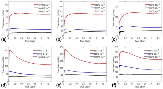
Figure 5.
Friction corrected flow stress curves for the full matrix of temperatures of CP-Ti TMC tests at; (a) 0.1 s−1; (b) 1 s−1; (c) 10 s−1. Ti-6-4 TMC tests at; (d) 0.1 s−1; (e) 1 s−1; and (f) 10 s−1.
The higher strength Ti-6-4 alloy exhibits flow stress behaviour which is more than twice the magnitude of the CP-Ti at the same temperature range, see Figure 5d–f. However, the low-strain flow behaviour is different for Ti-6-4: After rapid work hardening up to a yield point flow softening, due to the break-up of fine-scale plate-like secondary alpha, is observed particularly at the lowest test temperature of 850 °C. The degree of flow softening reduces with increasing temperature and at the super transus test temperature of 1050 °C, steady-state flow is exhibited.
Therefore, in summary, the flow behaviour of the two alloys are similar at higher temperatures, as both alloys exhibit steady-state flow. However, there is a mismatch in the magnitude of resistance to deformation: At a test temperature of 950 °C and strain rate of 1.0 s−1, the steady-state flow stress in CP-Ti and Ti-6-4 is 20 MPa and 50 MPa, respectively. At the lower end of the hot working range, there is greater contrast in the flow behaviour, particularly at low strains: The CP-Ti exhibits work hardening, whereas the Ti-6-4 displays flow softening. Forgers prefer to work with material that has steady-state flow, i.e. equivalent resistance to deformation at low and high strains, in order to control die filling and ensure homogeneous strain distributions. On the basis of the flow data in Figure 5, there potentially could be a large mismatch in flow stress behaviour, particularly at low strains, when coupling CP-Ti and Ti-6-4 in a dissimilar FAST preform.
3.2. Load-Displacement Curve Validation
Selected friction corrected load-displacement data representing the full range of loads comparing the FE simulation and hot compressed FAST CP-Ti and Ti-6-4 constituent samples are shown in Figure 6a,b, respectively. All tests showed an initial increase in load, followed by a linear increase until a point where the friction has more prominent influence on the load due to an increase in surface area, and a breakdown of the boron nitride lubricant between the platens and the workpiece. This frictional effect was most prominent in the 10 s−1 tests where after approximately 6 mm of displacement, there is an exponential increase in load, suggesting the friction is generally higher in these tests. There is excellent agreement between the experimental and simulation load-displacement data, although a slight underestimation was observed for tests at 10 s−1 strain rates. This provides confidence in the FE model as a reliable method for modelling simple uni-axial hot compressions of FAST material derived from powder.
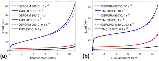
Figure 6.
Friction corrected load displacement curves comparing experimental TMC and FE simulations for; (a) CP-Ti alloy material post FAST consolidation; and (b) Ti-6-4 alloy material post FAST consolidation.
Figure 7 demonstrates the friction corrected load-displacement responses of FAST-DB samples, as compared to their corresponding single constituent FAST processed CP-Ti and Ti-6-4 alloy samples with a nominal test temperature of 950 °C. Both tests with strain rates of 0.1 and 10 s−1 show that Ti-6-4 has the higher flow stress compared to the CP-Ti alloy. The FAST-DB dissimilar alloy samples lie between the single alloy Ti-6-4 and CP-Ti load responses, suggesting the loads required for deformation could be estimated to determine the necessary machine capacities.
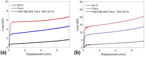
Figure 7.
Friction corrected load-displacement graphs comparing single alloy compressions with FAST-DB dissimilar alloy samples at a test temperature of 950 °C and a constant strain rate of; (a) 0.1 s−1; and (b) 10 s−1.
3.3. Small-Scale Hot Compression Forgings
Prior to simulating FAST-DB uni-axial hot compressions, initial simulations with varying friction conditions and alloy volume fraction ratios in the cylindrical TMC geometry were modelled, as shown in Figure 8.
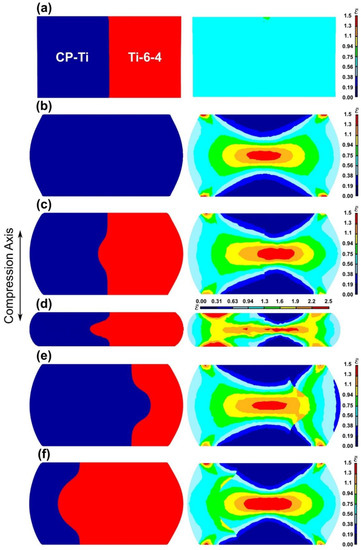
Figure 8.
Uni-axial compression FE simulations of FAST-DB samples, showing the bond interface location with corresponding strain distribution. Simulation conditions are a strain rate of 1 s−1, 850 °C, and a progressive friction factor of 0.2-0.5-0.9. (a) 1:1 alloy distribution with zero friction; (b) single alloy with friction; (c) 1:1 alloy distribution with friction; (d) 1:1 alloy distribution with friction at quarter deformation height; (e) dominant CP-Ti with friction; and (f) dominant Ti-6-4 with friction.
When the alloy volume fraction is 1:1 with zero friction the geometry remains rectangular; no barrelling is observed and the bond interface remains straight, see Figure 8a. As no friction is present the sample deforms uniformly resulting in a constant strain profile across the sample.
When the sample is a singular alloy and with the addition of a constant friction factor, barrelling occurs, as shown in Figure 8b. At the top and bottom of the compression sample, low strain regions exist that have little or no deformation. At the corners are local high-strain regions, while the curved edges remain low-strain. Towards the centre of the sample the strain increases where the maximum strain is located. A symmetrical strain profile is observed and strain continuation across the interface is excellent despite the deformation complexity.
The strain profile becomes more complex and loses symmetry with the addition of a second alloy and with friction still present, as shown in Figure 8c. The bond interface bulges into the CP-Ti alloy due to the comparably lower flow stresses at the hot compression temperature compared to the Ti-6-4 alloy. The highest strain region seen in the centre shifts slightly to the right into the higher flow stress alloy distorting the strain profile. Within the CP-Ti alloy the highest strain does not exceed 1.3, as a consequence of the Ti-6-4 displacing the CP-Ti alloy.
When the deformation is increased further to quarter height, the strain profile complexity increases significantly, see Figure 8d. The strain profiles of the two alloys begin to behave as individual constituent samples and the FE simulated bond line is under high strain. The Ti-6-4 alloy behaves similarly to Figure 8c, however, the maximum strain increases from 1 to 2.5. On the other hand, the CP-Ti alloy behaves unexpectedly with the highest strain occurring at the top and bottom surfaces, while in the centre of the sample the strain is only in the region of 1.6 to 1.9. Along the horizontal centreline is a high strain region between 1.9 and 2.5, where it is expected that dynamic recrystallisation processes are most likely to occur.
If the Ti-6-4 to CP-Ti alloy ratio is increased to 1:3, see Figure 8e, the bulging direction occurs in the Ti-6-4 alloy but to a greater extent compared to the 1:1 alloy volume fraction distribution condition. The highest strain remains in the centre of the sample but the continuation of constant strain across the interface does not occur. Instead there is a strain mismatch between the two alloys where the lower strength CP-Ti alloy accommodates a higher strain compared to the Ti-6-4 alloy.
As the Ti-6-4 to CP-Ti alloy ratio reverses to 3:1, see Figure 8f, the bulging becomes more dominant in the CP-Ti alloy, which has a lower resistance to deformation at the forging temperature compared to Ti-6-4. As a result, the bond interface bulging becomes broader into the CP-Ti during the hot compression. The highest strain remains in the centre of the sample and covers a slightly larger area (compared to Figure 8e), demonstrating the higher flow stress of the Ti-6-4 alloy. Again, at the interface there is a significant strain mismatch: The CP-Ti alloy has a strain between 0.75 and 0.94 along the majority of the interface, while the Ti-6-4 remains a similar strain only in the centre of the sample at the interface. The bond interface evolution demonstrated in these models in Figure 8 are also observed in the simulations with a diagonal starting bond interface morphology and the corresponding TMC samples.
Figure 9 shows a comparison between the FE simulations and macrographs of the sectioned compressed cylinders, deformed at representative nominal test conditions. The macrographs of these cylinders demonstrate the effect of differing friction factors and the influence of the bond interface morphology. Post uni-axial hot compression and after etching with Kroll’s reagent the visually brighter alloy is the Ti-6-4, while the brown tinted alloy is the CP-Ti. With the exception of the test at 850 °C with a 0.1 s−1 strain rate, the CP-Ti volume percentage decreased from the top to the bottom surface. There is excellent agreement of the bond interface morphology when comparing the simulations to the compression cylinders. Particularly considering the assumption of a linear interface between the top and bottom surfaces prior to the hot deformation. The simulations also assume isothermal conditions and only contained friction corrected data, so the flow of the simulation is likely to deviate from the compression cylinder and, consequently, the bulging in the simulations varies slightly.
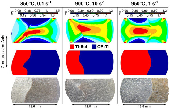
Figure 9.
Selected Ti-6-4 with CP-Ti FAST-DB TMC samples sectioned perpendicular to the bond interface after deformation at nominal test conditions as stated including effective strain profile, alloy profile, and macrograph of the sample. A progressive 0.2-0.5-0.9 progressive friction factor was used.
Cylinders tested under conditions of 850°C at 0.1 s−1 and 900 °C at 10 s−1 demonstrate the dependence of the alloy distribution. Although Ti-6-4 has a higher flow stress at the test temperature, the CP-Ti displaces the Ti-6-4 due to the dominance of the CP-Ti alloy in the sample. The cylinder tested under conditions of 950 °C at 1 s−1 has a greater percentage of Ti-6-4 and, consequently, displaces the CP-Ti alloy during the upset forging. The post deformation bond interface morphologies are likely formed due to a combination of prior bond interface morphologies, alloy distribution from top to bottom, and the hot deformation conditions. These findings demonstrate the importance of controlling the bond interface prior to hot working. It is envisaged that there will be greater control through process development which will occur as FAST-DB development elevates through the technology readiness levels.
3.4. Large-Scale, Near-Net Shape Forging
Two eye-bolts were sectioned and analysed during this study: The first being eye-bolt 1 (EB1) from a FAST-DB preform of Ti-6-4 and CP-Ti. Eye bolt 2 (EB2) was processed from a FAST-DB preform of Ti-6-4 and Ti-5553, shown in Figure 10a and Figure 11a, respectively. Visually, both eye-bolts show excellent bond integrity with no cracking at the bond interface. In EB1, the two alloys can be distinguished from each other by the differences in amount of flash at the top and bottom of the forging, see Figure 10a. At the forging temperature, the CP-Ti alloy has a lower flow stress compared to the Ti-6-4 alloy and thus, the former alloy creates more flash for given height reduction. The die fill was mostly complete; however, the material did not completely fill the Ti-6-4 area on the inside of the thinner “eye” section. In addition, the bond line has been revealed due to the different oxide scale colours of the two alloys on the surface of the component. It provides an initial estimation of the bond interface region, which is particularly valuable as it saves time and resources which would be beneficial when evaluating new components.
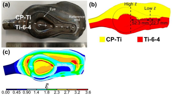
Figure 10.
(a) Photograph of the Ti-6-4 with CP-Ti near-net shape forging, eye-bolt 1; (b) corresponding FE model showing the alloy distribution; and (c) the corresponding FE model showing the effective strain distribution. Approximate forging temperature between 860 and 878 °C, with a total of nine hammer steps.
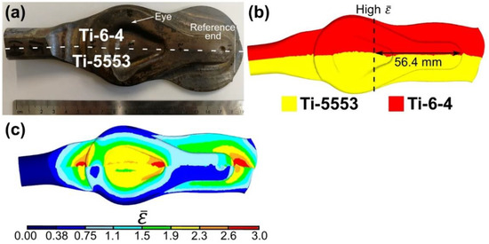
Figure 11.
(a) Photograph of the Ti-6-4 with Ti-5553 near-net shape forging, eye-bolt 2; (b) corresponding FE model showing the alloy distribution; and (c) the corresponding FE model showing the effective strain distribution. Approximate forging temperature between 860 and 878 °C, with a total of nine hammer steps.
In EB2, the alloys can be determined by the differences in die fill. The Ti-6-4 alloy filled the die similarly to that observed in EB1. Conversely, the Ti-5553 alloy demonstrated limited die fill on the inside of the “eye” section, due to the higher flow stress of the high strength metastable beta alloy at the forging temperature.
The sectioning strategy for the two eye bolts was selected in order to validate the FE model bond interface predictions and corresponding strain distribution in a high and low strain region. In EB1, the low and high strain cross-sections were located approximately 22.7 mm and 75.0 mm, respectively, from the reference end of the eye-bolt and are discussed further in Section 3.5 and Section 3.6, see Figure 10b. In EB2, the high strain cross section was located at approximately 56.4 mm from the reference end, see Figure 11b.
3.5. Comparison of FE Model with Near Net Shape Forging
Figure 12 shows the evolution of the FE model and the shape of EB2 after each individual closed-die forging step. It provides a demonstration of the robust FE modelling software for the simulation of a relatively uncontrolled forging route for FAST-DB preforms.
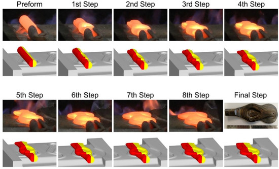
Figure 12.
FE model and corresponding photographs of the eye-bolt 2 (Ti-5553 with Ti-6-4) shape evolution after each forging step.
Figure 13 compares the FE model to a low strain region location shown in Figure 10b of EB1. The first observation that can be made is that the prediction of the bond interface morphology seen in Figure 13b is in good agreement with the macrographs, considering the complex, multi-step forging. There is slightly more curvature of the bond interface in the macro image and the CP-Ti material has spread further along the upper and lower contact surfaces during the hot working process. This is likely to be a result of the continually varying friction conditions between the workpiece and the dies, compared to a constant friction factor used in the simulation.
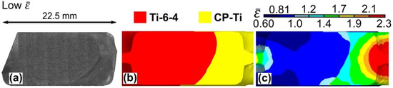
Figure 13.
(a) Photograph of the low strain cross-section of the eye-bolt 1 forging (Ti-6-4 and CP-Ti) from Figure 10b; (b) corresponding simulation showing the alloy distribution; and (c) the corresponding simulation showing the effective strain distribution. Approximate forging temperature between 860 and 878 °C, with a total of nine hammer steps.
Figure 13a shows the macrostructures evolution across the low strain region cross-section in EB1. Across the whole bond interface, similar macrostructural flow characteristics are observed in both alloys. In general, the CP-Ti alloy microstructure has been deformed significantly, while the Ti-6-4 alloy is only slightly deformed. This is confirmed in the predicted strain profile of the cross-section shown in Figure 13c. This is an example where there is a clear mismatch in flow behaviour at the interface, yet there is no evidence of delamination or cracking at the bond line.
The high strain cross section region of EB1 is shown in Figure 14a, consisting of the Ti-6-4 alloy on the left hand side and the CP-Ti alloy on the right. The central “eye” region of the workpiece is quite complex including long banded regions of recrystallised Ti-6-4, approximately 25–50 µm wide. The Ti-6-4 alloy has flowed from the centre of the section and bulged into the CP-Ti side, once again, demonstrating the mismatch in flow stresses between the two alloys at the approximate forging temperature range of 860–878 °C. Upon further inspection, it appears that the CP-Ti alloy extends along the bottom surface to the centre of the forged shape. However, there is no evidence of the CP-Ti alloy along the top surface suggesting the Ti-6-4 alloy has displaced the alloy completely into the CP-Ti side.
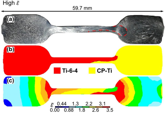
Figure 14.
(a) Photograph of the high strain cross-section of the eye-bolt 1 forging from Figure 10b; (b) ccorresponding simulation showing the alloy distribution; and (c) the corresponding simulation showing the effective strain distribution. Approximate forging temperature between 860 and 878 °C, with a total of nine hammer steps.
In the bulk Ti-6-4 and CP-Ti alloys, the grain structure is only slightly deformed due to limited material flow within the component. Towards the edges of these sections, and as the width of the component reduces, extremely fine grains are observed as a result of the high strains produced in these regions. This continues into the thin section, as can be seen in Figure 14a. The corresponding simulation alloy distribution, seen in Figure 14b, has very good agreement considering the magnitude of the displaced CP-Ti alloy. Notably the simulation has captured the displacement of the CP-Ti alloy and the displacement of the Ti-6-4 into the CP-Ti side. The predicted bulging form and curvature of the bond line deviates from the experimental forging and the thickness of the CP-Ti alloy in the thin “eye” region is slightly overestimated. However, the model could be developed further to improve the accuracy by increasing the number of elements while also decreasing the element size. The varying friction between the workpiece and the dies is difficult to determine, so a constant friction factor was used.
3.6. High Strain Microstructural Analysis
Microstructural analysis of high strain regions of EB1, which is located at 52.3 mm from the reference end of the forging, as shown in Figure 10b, was carried out to assess the microstructural evolution adjacent to the diffusion bond interface (see Figure 15). Site “a” is in the centre of the Ti-6-4 side and shows a typical low strained, lamellar Ti-6-4 microstructure, consisting of slightly elongated grains perpendicular to the compression axis compared to in the as-FAST condition. Additionally, within the Ti-6-4 side is site “b”, which is situated on the edge of the sample showing a crack propagation from the surface into the sample in a recrystallised region. The crack does not appear to be a geometrical defect, but rather a crack that may have formed during the high strain rate, multi-step forging. Site ‘c’ is also located in the Ti-6-4 side, but in the region transitioning into the thin “eye” cross-section of the forging. The recrystallised band region shown at site “b” also passes through site “c” and continues into the thin “eye” cross-section. Under cross-polarised light, the recrystallised region is highlighted as a lighter shade of grey compared to the region that starts from the bottom of the component, suggesting the grains may have been orientated in a preferential crystallographic direction during the forging process. Site “d” is a continuation of the recrystallised band which is observed throughout the thin “eye” cross-section. At site ‘e’, the first observation of the bond interface between Ti-6-4 and CP-Ti is shown at the bottom of the micrograph. The interface is difficult to distinguish due to the deformed microstructures, however, the Ti-6-4 remains as a typical low strain transformed β microstructure, while the CP-Ti is high strained. Site ‘f’ lies in the thin “eye” cross-section, as clearly shown by the severely deformed microstructures in both the Ti-6-4 and CP-Ti alloys. A fine-grain recrystallised region passes through the Ti-6-4 alloy to eventually make direct contact with the CP-Ti. At site “g” this contact is observed. The CP-Ti shows quite a fine grain structure in contact with the fine Ti-6-4 microstructure at the bond interface. Slightly further from the bond interface at approximately 200 µm into the Ti-6-4, the grain size becomes coarser and shows a highly deformed grain structure instead. Site “h”, at the end of the bulging Ti-6-4 region, shows a return to a constant moderate strain Ti-6-4 microstructure. The CP-Ti alloy grain size also increases slightly. Site “i” provides another demonstration of how the grain size can vary towards the bond interface. In this micrograph, the CP-Ti gradually decreases in grain size towards the bond interface while the Ti-6-4 remains fairly constant. This behaviour is similar to the suggested local recrystallisation that occurs at the highly-strained diffusion bond interface, when CP-Ti with Ti-6-4 compression samples are plastically deformed. Finally, site “j” shows the CP-Ti microstructure in the alloy section, consisting of an acicular microstructure.
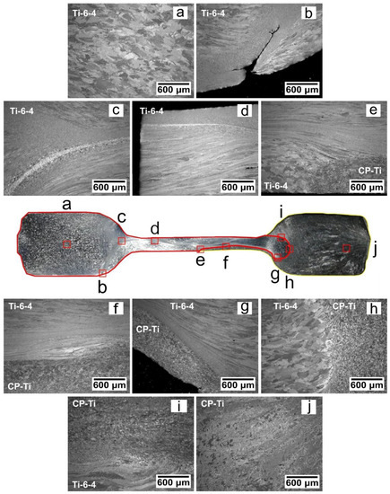
Figure 15.
Light micrographs of regions of interest in the high strain cross-section of eye-bolt 1 (Ti-6-4 with CP-Ti): (a) Bulk Ti-6-4 microstructure; (b) exterior crack initiated due to excessive strain; (c) recrystallised Ti-6-4 region; (d) a comparison between a medium strain Ti-6-4 and high strain at the contact surface; (e) Ti-6-4 with CP-Ti interface at intermediate strains; (f) high strain bond interface for both alloys; (g) bond interface consisting of fine grained Ti-6-4 and small grained CP-Ti; (h) bond interface consisting of low strain Ti-6-4 and high strain CP-Ti; (i) bond interface consisting of low strain Ti-6-4 and high strain CP-Ti; and (j) bulk CP-Ti in an medium strained region.
A high-strain region in EB2 was also microstructurally analysed at 56.4 mm from the reference end, as defined in Figure 11b. The varying microstructures across the eye-bolt, both in the side sections and also in the thin “eye” section, are shown in Figure 16.
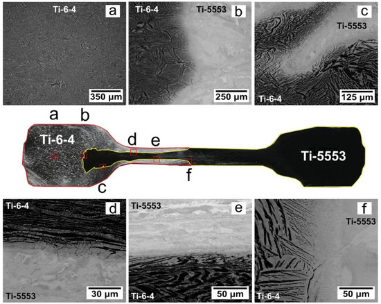
Figure 16.
High-resolution backscatter micrographs of regions of interest in the high strain cross section of eye-bolt 2 (Ti-5553 with Ti-6-4); (a) bulk Ti-6-4 microstructure in the side section; (b) bond interface in a relatively low strain location; (c) and an example of a wavy interface; (d) high-strain bond interface on the upper side of the thin section; (e) the high-strain bond interface on the lower side of the thin section; and (f) the bond interface at the middle of the eye-bolt.
Site “a” shows the microstructure towards the middle of the Ti-6-4 region and consists of a typical Widmanstätten microstructure, which has been slightly deformed by a small increase in strain in this region. Site ‘b’ is located on the bond interface within the Ti-6-4 alloy region and is comparable to an as-FAST microstructure [19]. The Ti-6-4 has a similar microstructure to that observed at site “a”, suggesting similar strain histories. The microstructure changes quite abruptly from the Ti-6-4 into the Ti-5553, as evidenced by the disappearance of the α laths, shown as the darker bands in Figure 16b. The Ti-5553 comprises of a fine sub-structure, which is absent of any prominent microstructural features, as a result of the fully-retained β microstructure produced from soaking the workpiece slightly above the β transus and subsequently quenched to below the β transus. At high magnifications using SEM analysis no evidence of the α precipitates were observed, as the α phase does not have sufficient time to precipitate out at the fast cooling rates. Some lighter and darker areas exist in the Ti-5553 microstructure, which are likely to be deformed grain boundaries and grain sub-structures. Site “c” shows an excellent example of how robust the bond interface can be when severely deformed with a wavy prior bond interface morphology; no defects or evidence of cracking are evident at the interface. Site “d” and “e” represent the Ti-5553 with Ti-6-4 bond interface at high strains, located within the thin section of the workpiece. Each micrograph can be divided into three distinct regions. The first is the bulk Ti-5553 microstructure, followed by a bonding region and, finally, the Ti-6-4 bulk microstructure. The bulk alloys are severely deformed, and there is clear evidence of the Ti-6-4 alloy flow at site “d”. The bonding region at site “d” has a darker appearance than the bulk Ti-5553 and contains fine α phase, which gradually evolves into the bulk Ti-6-4. The α phase in the bonding region follows the grain boundaries, which are more favourable paths for diffusion. Site “f” shows a high magnification micrograph of the interface where the two alloys meet each other in the centre of workpiece. There is evidence of diffusion at the interface by a grain containing the α phase on one side and an absence on the other, demonstrated by [19].
4. Conclusions
For the first time, the FAST process has been industrial-scaled using angular and spherical morphology powders to produce near-net shape forgings containing dissimilar titanium alloys.
The material flow of FAST-DB compression samples is dependent on the flow stresses of the titanium alloys used, the processing conditions, and also the volume fraction of each alloy. Even though there is a mismatch in the magnitude of flow stress between alloys and flow characteristics, for example, Ti-6-4 exhibits flow softening and CP-Ti work hardening, excellent structural bond integrity is maintained throughout.
In high strain regions in eye-bolts 1 and 2, the bond interface has been shown to retain high integrity despite the relatively uncontrolled drop forging processing. There is an absence of processing defects at the interface providing confidence that the bonds could endure typical titanium thermomechanical processing routes in aerospace and automotive applications.
In Ti-6-4 with CP-Ti and Ti-6-4 with Ti-5553 bond combinations, the lower flow stress alloy at the forging temperature was displaced by the higher flow stress alloy, in both high strain and low strain regions. In the future, alloy compatibility of each bond combination needs to be considered, specifically differences in flow stresses. In addition, measurements of residual stress profiles across forged dissimilar bonds to ensure long term durability.
There was excellent agreement between the FE simulations of the closed-die forging process of Ti-6-4 with CP-Ti bond combinations in the high strain region. The ability to predict the thermomechanical responses of a FAST-DB component, is a key milestone in the development of processing titanium alloy components by this approach.
Author Contributions
J.P. conducted the experimental work as part of his Ph.D study. M.J. was the academic supervisor. J.P. and M.J. conceived the idea and designed the experiments.
Funding
This research was funded by Engineering and Physical Sciences Research Council’s Advanced Metallic Systems Centre for Doctoral Training (grant number EP/G036950/1).
Acknowledgments
The authors acknowledge Adam Tudball from Kennametal Ltd. UK for support with processing the large FAST-DB billets. We gratefully acknowledge David Lunn and the staff at W.H. Tildesley Ltd. for the drop forging trials and useful discussions. Finally, thanks to Dean Haylock from The University of Sheffield for technical assistance, and Nicholas Weston, Ben Thomas, and Bhushan Rakshe for useful discussions.
Conflicts of Interest
The authors declare no conflict of interest.
References
- García, A.M.M. BLISK fabrication by linear friction welding. In Advances in Gas Turbine Technology; Benini, E., Ed.; InTechOpen: London, UK, 2011; pp. 411–434. [Google Scholar]
- Guo, Y.; Chiu, Y.; Attallah, M.M.; Li, H.; Bray, S.; Bowen, P. Characterization of dissimilar linear friction welds of α-β Titanium alloys. J. Mater. Eng. Perform. 2012, 21, 770–776. [Google Scholar] [CrossRef]
- Weston, N.S.; Derguti, F.; Tudball, A.; Jackson, M. Spark plasma sintering of commercial and development titanium alloy powders. J. Mater. Sci. 2015, 50, 4860–4878. [Google Scholar] [CrossRef]
- Menapace, C.; Vicente, N., Jr.; Molinari, A. Hot forging of Ti–6Al–4V alloy preforms produced by spark plasma sintering of powders. Powder Metall. 2013, 56, 102–110. [Google Scholar] [CrossRef]
- Weston, N.S.; Jackson, M. FAST-forge − A new cost-effective hybrid processing route for consolidating titanium powder into near net shape forged components. J. Mater. Process. Technol. 2017, 243, 335–346. [Google Scholar] [CrossRef]
- Yang, Y.F.; Imai, H.; Kondoh, K.; Qian, M. Comparison of spark plasma sintering of elemental and master alloy powder mixes and prealloyed Ti6Al4V powder. Int. J. Powder Metall. 2014, 50, 41–47. [Google Scholar]
- Yang, Y.F.; Imai, H.; Kondoh, K.; Qian, M. Enhanced homogenization of vanadium in spark plasma sintering of Ti-10V-2Fe-3Al alloy from titanium and V-Fe-Al master alloy powder blends. JOM 2017, 69, 663–668. [Google Scholar] [CrossRef]
- Long, Y.; Zhang, H.; Wang, T.; Huang, X.; Li, Y.; Wu, J.; Chen, H. High-strength Ti–6Al–4V with ultra fine-grained structure fabricated by high energy ball milling and spark plasma sintering. Mater. Sci. Eng. A 2013, 585, 408–414. [Google Scholar] [CrossRef]
- Long, Y.; Wang, T.; Zhang, H.Y.; Huang, X.L. Enhanced ductility in a bimodal ultra fi ne-grained Ti–6Al–4V alloy fabricated by high energy ball milling and spark plasma sintering. Mater. Sci. Eng. A 2014, 608, 82–89. [Google Scholar] [CrossRef]
- Vajpai, S.K.; Ota, M.; Watanabe, T.; Maeda, R.; Sekiguchi, T.; Kusaka, T.; Ameyama, K. The development of high performance Ti-6Al-4V alloy via a unique microstructural design with bimodal grain size distribution. Metall. Mater. Trans. A 2015, 46, 903–914. [Google Scholar] [CrossRef]
- Manière, C.; Kus, U.; Durand, L.; Mainguy, R.; Huez, J.; Delagnes, D.; Estournès, E. Identification of the norton-green compaction model for the prediction of the Ti–6Al–4V densification during the spark plasma sintering process. Adv. Eng. Mater. 2016, 18, 1720–1727. [Google Scholar] [CrossRef]
- Garbiec, D.; Siwak, P.; Mróz, A. Effect of compaction pressure and heating rate on microstructure and mechanical properties of spark plasma sintered Ti6Al4V alloy. Arch. Civ. Mech. Eng. 2016, 16, 702–707. [Google Scholar] [CrossRef]
- Calvert, E.; Wynne, B.; Weston, N.; Tudball, A.; Jackson, M. Thermomechanical processing of a high strength metastable beta titanium alloy powder, consolidated using the low-cost FAST-forge process. J. Mater. Process. Technol. 2018, 254, 158–170. [Google Scholar] [CrossRef]
- Crosby, K.; Shaw, L.L.; Estournes, C.; Chevallier, G.; Fliflet, A.W.; Imam, M.A. Enhancement in Ti–6Al–4V sintering via nanostructured powder and spark plasma sintering. Powder Metall. 2014, 57, 147–154. [Google Scholar] [CrossRef]
- Voisin, T.; Monchoux, J.; Durand, L.; Karnatak, N.; Thomas, M.; Couret, A. An innovative way to produce γ-tial blades: Spark plasma sintering. Adv. Eng. Mater. 2015, 17, 1408–1413. [Google Scholar] [CrossRef]
- Munir, Z.A.; Anselmi-Tamburini, U.; Ohyanagi, M. The effect of electric field and pressure on the synthesis and consolidation of materials: A review of the spark plasma sintering method. J. Mater. Sci. 2006, 41, 763–777. [Google Scholar] [CrossRef]
- Munir, Z.A.; Quach, D.V.; Ohyanagi, M. Electric current activation of sintering: A review of the pulsed electric current sintering process. J. Am. Ceram. Soc. 2011, 94, 1–19. [Google Scholar] [CrossRef]
- Manière, C.; Nigito, E.; Durand, L.; Weibel, A.; Beynet, Y.; Estournès, C. Spark plasma sintering and complex shapes: The deformed interfaces approach. Powder Technol. 2017, 320, 340–345. [Google Scholar] [CrossRef]
- Pope, J.J.; Calvert, E.L.; Weston, N.S.; Jackson, M. FAST-DB: A novel solid-state approach for diffusion bonding dissimilar titanium alloy powders for next generation critical components. J. Mater. Process. Technol. 2019, 269, 200–207. [Google Scholar] [CrossRef]
- Roebuck, B.; Lord, J.D.; Brooks, M.; Loveday, M.S.; Sellars, C.M.; Evans, R.W. Measurement of flow stress in hot axisymmetric compression tests. Mater. High Temp. 2006, 23, 59–83. [Google Scholar] [CrossRef]
- DEFORM 3D; v11.2; Scientific Forming Technologies Corporation: Columbus, OH, USA, 2018.
- SolidWorks; v25; Dassault Systemes: Waltham, MA, USA, 2017.
© 2019 by the authors. Licensee MDPI, Basel, Switzerland. This article is an open access article distributed under the terms and conditions of the Creative Commons Attribution (CC BY) license (http://creativecommons.org/licenses/by/4.0/).