Article

Springback Calibration of a U-Shaped Electromagnetic Impulse Forming Process

1
Light Alloy Research Institute, Central South University, Changsha 410083, China
2
State Key Laboratory of High Performance Complex Manufacturing, Central South University, Changsha 410083, China
3
College of Mechanical and Electrical Engineering, Central South University, Changsha 410083, China
4
School of Material and Energy, Guangdong University of Technology, Guangzhou 510000, China
*
Author to whom correspondence should be addressed.
Metals 2019, 9(5), 603; https://doi.org/10.3390/met9050603
Submission received: 31 March 2019 / Revised: 9 May 2019 / Accepted: 17 May 2019 / Published: 24 May 2019
(This article belongs to the Special Issue Forming Processes of Modern Metallic Materials)

Abstract

:
A three-dimensional (3D) finite-element model (FEM), including quasi-static stamping, sequential coupling for electromagnetic forming (EMF) and springback, was established to analyze the springback calibration by electromagnetic force. Results show that the tangential stress at the sheet bending region is reduced, and even the direction of tangential stress at the bending region is changed after EMF. The springback can be significantly reduced with a higher discharge voltage. The simulation results are in good agreement with the experiment results, and the simulation method has a high accuracy in predicting the springback of quasi-static stamping and electromagnetic forming.

1. Introduction

In recent years, lightweight products are more commonly used because of the requirement for energy conservation. For this reason, aluminum and magnesium alloys as well as high-strength steel applications have been produced in increasing numbers. However, the common springback behavior during sheet-metal bending greatly affects both size and shape precision of produced parts.
During bending, the sheet deformation under an external load consists of both plastic and elastic deformation. When the external load is removed, the elastic strain is recovered. This results in a geometrical deviation from the ideal target product [1,2]. More specifically, the springback is the deviation between the shape before and after unloading, which is caused by the elastic recovery of the bending region. Since all metal materials have elastic modulus, springback is an unavoidable problem in sheet forming processes. In comparison with traditional low-carbon steel, the springback tendency of aluminum alloy is very pronounced. Therefore, the effective prediction and control of springback is important to improving the precision of bent aluminum-alloy parts.
Electromagnetic forming (EMF) is a high-speed forming method that can deform a workpiece through magnetic force using the electromagnetic induction theorem. The deformation speed of electromagnetic forming is extremely fast, often reaching 300 m/s. Compared with traditional stamping, this can be seen as a high-speed deformation process. EMF can significantly enhance plastic strain due to the inertia effect [3,4]. Therefore, the EMF process can increase the formability of metal sheets and reduce both springback and wrinkling [5,6]. It was reported that EMF technology could be used for aluminum sheet/tube forming, bending, joining, welding, cutting, and calibration of parts. For example, Guo et al. [7] used electromagnetic incremental forming (EMIF) to obtain an integral curvature panel with the grid ribs stiffened. Xiong et al. [8] designed a V-bending electromagnetic forming (EMF) method though experimentation and simulation to solve the shape difference between the formed part and the desired part. However, only a few simple-shaped parts can be manufactured using these methods.
Thus, electromagnetically assisted sheet-metal stamping (EMAS), which combines the advantages of high-speed forming into the traditional stamping process, has been used widely. For EMAS, the sheet is bent by quasi-static stamping firstly, then the working coils are setup at the sheet bending area to generate a high magnetic force. Finally, an increased formability was found in EMAS compared with the traditional stamping process [9]. Many researchers have studied the effect of EMAS on springback in various experiments. For example, Shang et al. [10] established the V-bending method and evaluated the effect of pulsed magnetic force on springback using 2024-T3 aluminum sheets. Liu et al. [11] and Sun et al. [12] established the U-shaped parts by electromagnetically assisted bending using 5052-O aluminum sheets, respectively. Iriondo et al. [13,14] established the forming of L-shaped parts and analyzed the effect of pulsed electromagnetic force on the springback of 5754 aluminum alloy and DP600 high-strength steel. Woodward et al. [15] designed disposable actuators to control and minimize springback. Therefore, it was recognized in the field of electromagnetic forming EMF can reduce springback. However, the question of why the angle can be controlled after EMF process was not clearly answered in those papers.
In this paper, the three-dimensional (3D) finite-element model (FEM) utilizing ABAQUS and ANSYS software was used to describe the mechanism of electromagnetic impulse calibration.

2. FEM of Electromagnetic Impulse Calibration

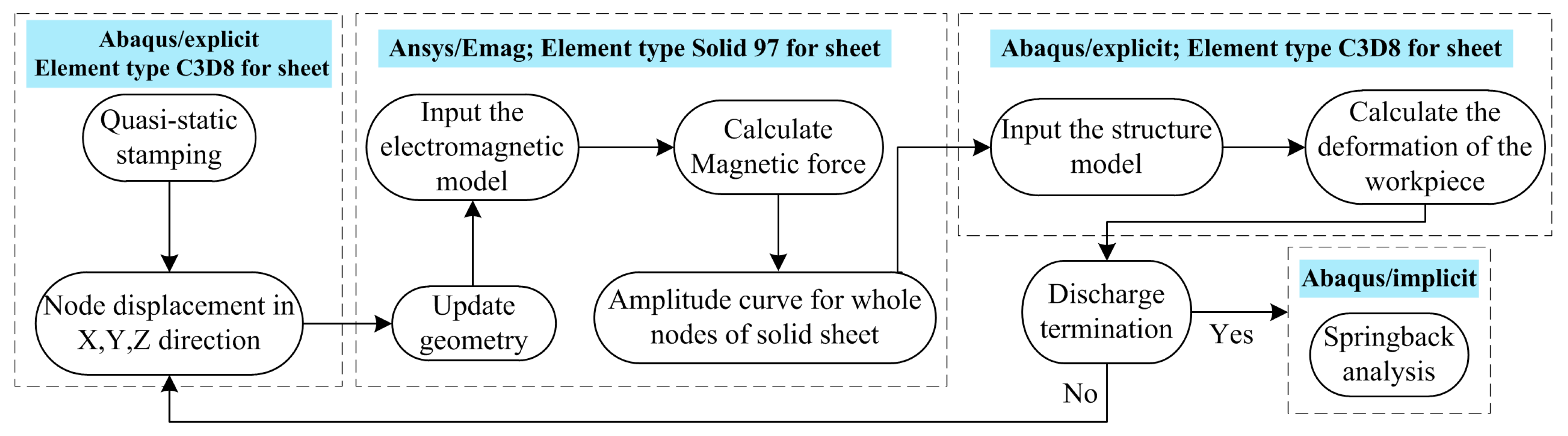
2.1. Simulation Strategy

There are two main simulation methods for electromagnetic forming: (1) the loose coupling method, and (2) the sequential coupling method. In [16], we analyzed the differences between the two methods. If the magnetic forces calculated are not based on the updated EM model, the simulation approach can be deemed the loose coupled method. For the EMF, the sequential coupling method has higher calculation accuracy because it considers the effect of workpiece deformation on magnetic field calculation. In this paper, quasi-static stamping, sequential coupling for electromagnetic forming, and springback have been all considered, and the simulated flowchart can be seen in Figure 1. The effects of local electromagnetic momentum are neglected and the hypothesis of a symmetric Cauchy stress tensor is used. The ANSYS/emag software, which uses Maxwell electromagnetic equations to calculate the electromagnetic force, was used for electromagnetic field simulation. The ABAQUS/explicit software was used to calculate the quasi-static stamping and dynamic deformation process. When the deformation is terminated, the springback of the sheet is calculated by ABAQUS/implicit software.

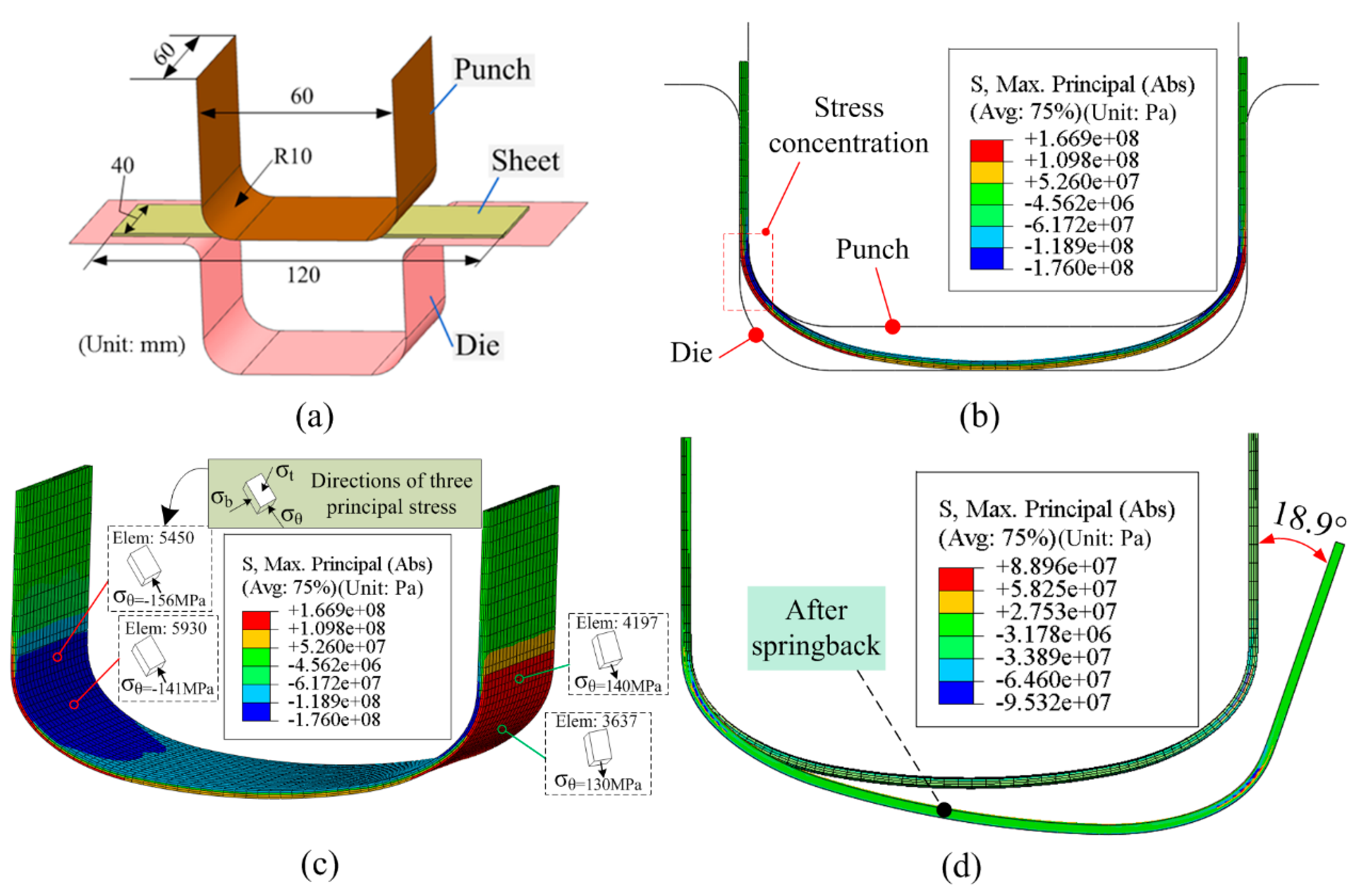
2.2. Structure Field Model

The simulation data in this paper were taken from published studies by Liu et al. [11] and Sun et al. [12]. The main parameters of the EMF equipment were: rated voltage (5 kV), and capacitance (774 μF). The detailed experimental conditions were as follows: (1) The elasticity modulus of a AA5052-O aluminum-alloy sheet was set as 68 GPa, the Poisson’s ratio was set as 0.33, the density was set as 2.7 × 10³ kg/m3, and the yield strength was set as 90 MPa. The length, width, and thickness of the sheets were 120 × 40 × 1 mm. (2) The length and the corner radius of the punch were 60 and 10 mm, respectively, as shown in Figure 2a. The gap between the punch and die was set to 1.05 mm. The quasi-static constitutive behavior of the AA5052-O sheet is described by Equation (1).
For electromagnetic forming, inaccurate simulation results could be obtained if the strain rate effect is not considered. To consider the effect of a high strain rate on the forming process, the behavior of viscoplastic material was modeled with a rate-dependence law (Cowper–Symonds power law) in ABAQUS finite-element analysis software. Cui et al. [17] produced large-scale ellipsoid parts using electromagnetic incremental forming combined with stretch forming. The Cowper–Symonds power law was used to accurately predict the high-speed forming process with multi-steps of coil discharge and stretching. Thus, the Cowper–Symonds constitutive model was used in this paper as shown in Equation (2).
σ s = 364.16 ε 0.25
σ = σ s ( 1 + ( ε ˙ P ) m )
where σ is the dynamic flow stress, σs is the quasi-static constitutive behavior of the sheet, ε ˙ is the strain rate, P = 6500 s−1, and m = 0.25 is the specific parameter of aluminum alloy.
The ABAQUS/explicit software was used to create a three-dimensional (3D) U-bending model, as shown in Figure 2a. To enhance the calculation speed, the punch and die were treated as rigid bodies. The element type of the punch and die was R3D4. The sheet was meshed using C3D8, an eight-node hexahedral element. Contact conditions between the punch and sheet, as well as the sheet and die, have been considered in this paper. The friction coefficient was set to 0.1. The sheet-center bulged during the quasi-static stamping. According to the experimental condition in [11,12], we set a certain displacement for the punch moves to ensure that the sheet center would just make contact with the die. The deformed sheet can be seen in a two-dimensional (2D) view in Figure 2b. Based on the stamping results, it can be found that the maximum principal stress (Abs) occurred predominantly at the sheet corner, as shown in Figure 2c. According to the principle of plastic forming, the three principal stresses during sheet bending were in the tangential direction, the width direction, and the thickness direction, respectively. In order to better understand the changes of stress during forming, the three principal stress components were defined as following: σθ, tangential component; σb, width component; and σt, thickness component. As the principal stresses along the tangential direction have a great effect on springback, the distribution of tangential stress (σθ) on the sheet at different times should be analyzed. However, the distribution of tangential stress (σθ) cannot be directly selected in the Abaqus software. Thus, the tangential stress was judged as special elements based on element stress vector. As shown in Figure 2c, the tangential compression and tensile stress occurred at the inner and outer layer of the sheet corner region after stamping, respectively. Figure 2d shows the 2D view before and after the springback. The springback angle was about 18.9°, and the radius of the bend region changed to about 12 mm.

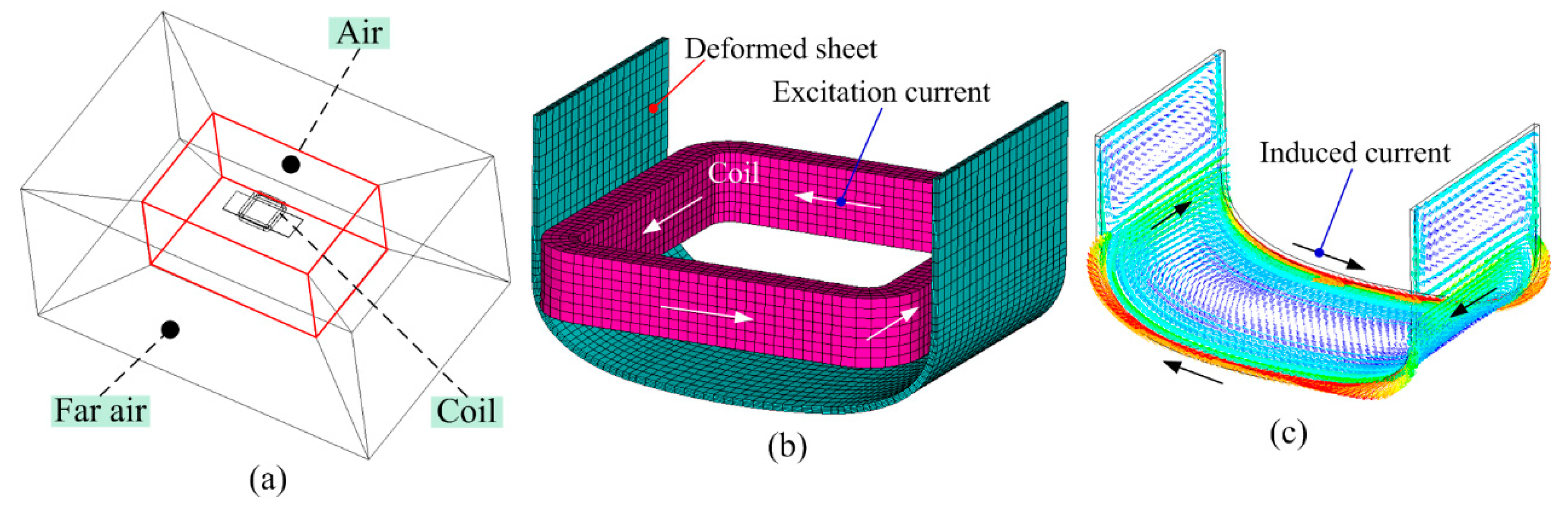
2.3. Electromagnetic Field Model

Based on the geometric dimensions of the coil and the sheet, a 3D electromagnetic field model was established, as shown in Figure 3a. The electromagnetic field model consisted of the far-air region, air region, coil, and sheet. The element types for the far-air region, air region, coil, and sheet were infin111, solid97, solid97, and solid97, respectively. Based on the deformed sheet in Figure 2c, the electromagnetic field model was updated. The updated models contained sheet and coil, as shown in Figure 3b. Figure 3c shows the induced current distribution on the sheet metal after coil discharge. The current on both sides of the width of the sheet metal and the current at the corner region of the sheet metal constitute a current loop. The direction of induced current on the sheet metal was opposite to the current loaded into the coil.
Sun et al. [12] reported the current density flowing through the coil for a 1 × 10 mm section at 3 kV. According to our calculation, we can obtain the current curve during the coil discharge at 3 kV. At 60 μs, the current reaches its maximum value of 42 kA. In EMF, the discharge current, I (t), flowing in the coil is approximately described by Equation (3). For an EMF device, the capacitance (C), inductance (L), and resistance (R) were always kept consistent. Figure 4 shows the current flowing through the coil at different voltages.
I ( t ) = U C L e R 2 L t sin 1 L C t

3. Results

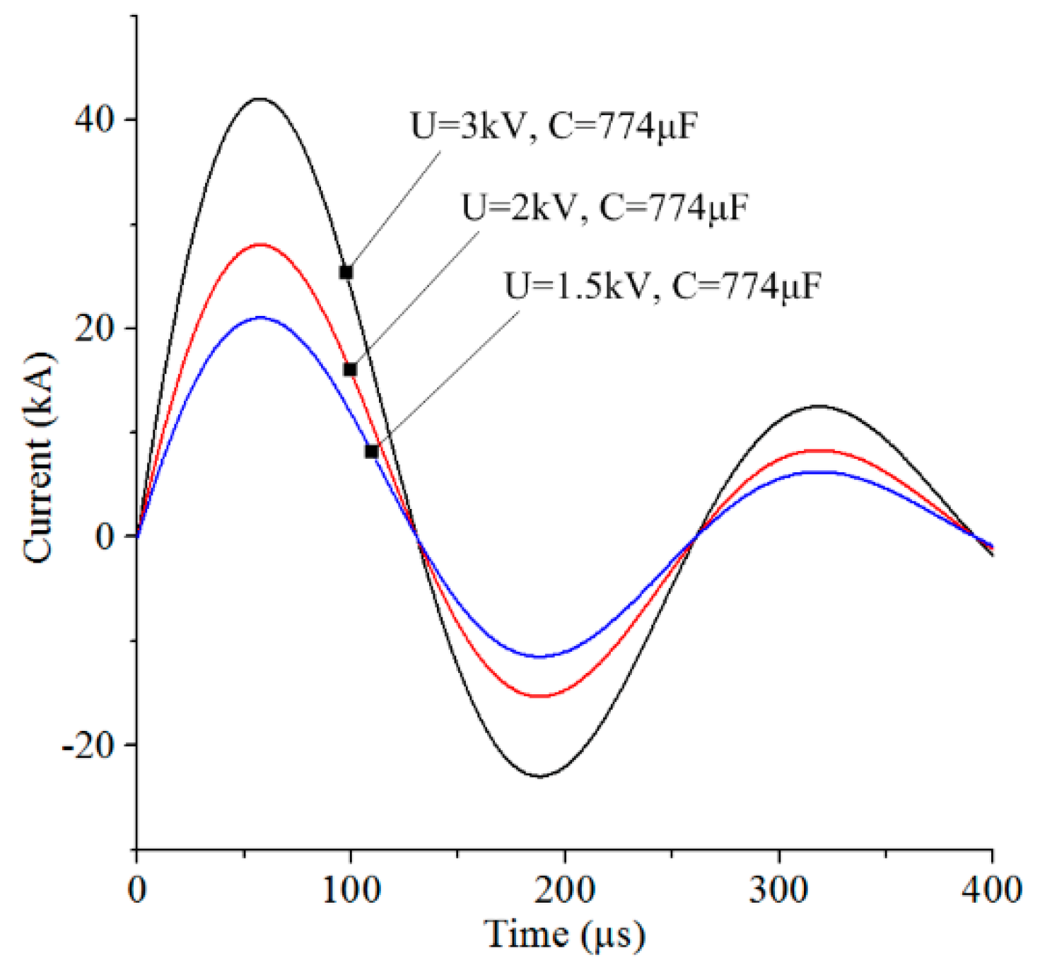
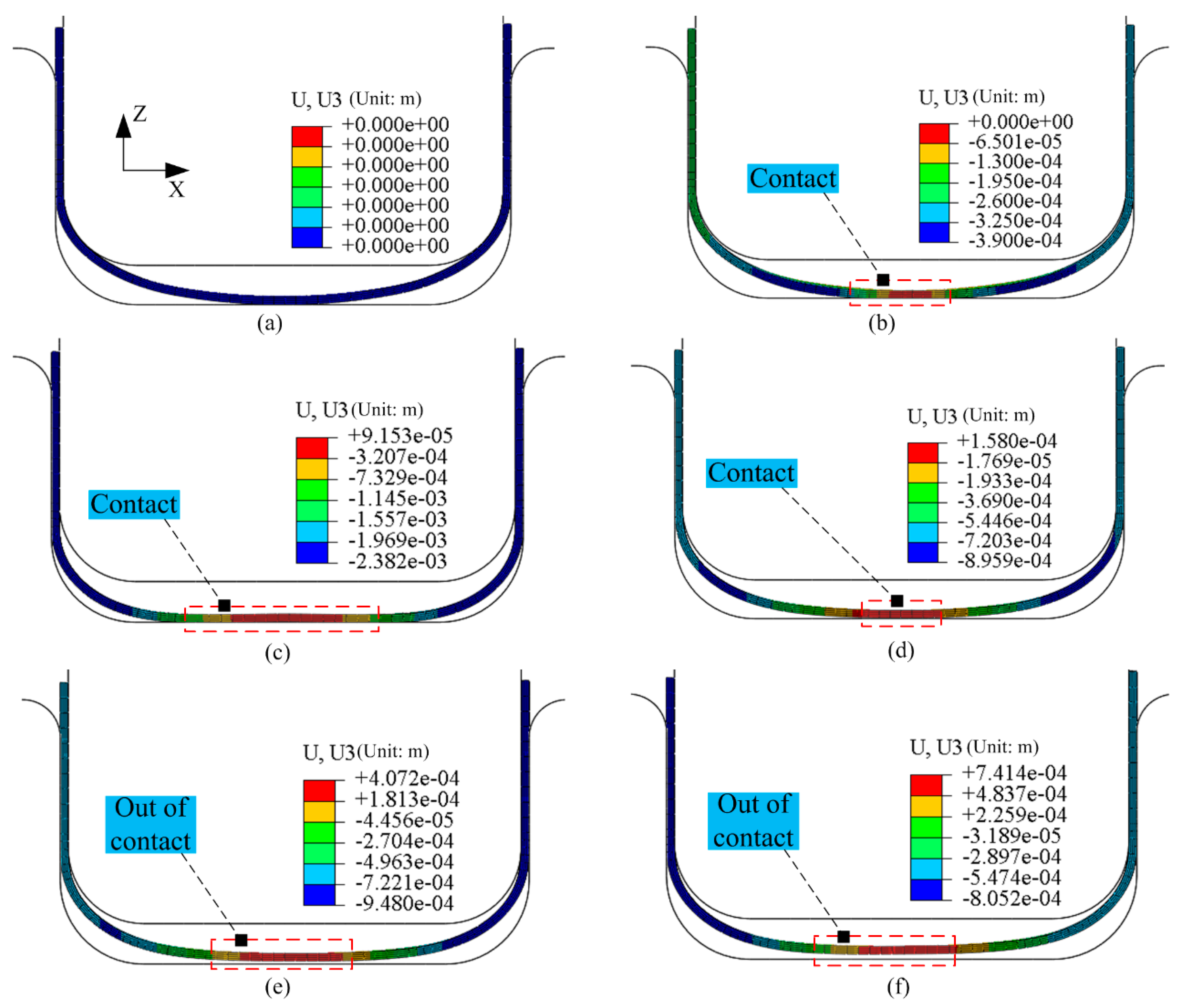
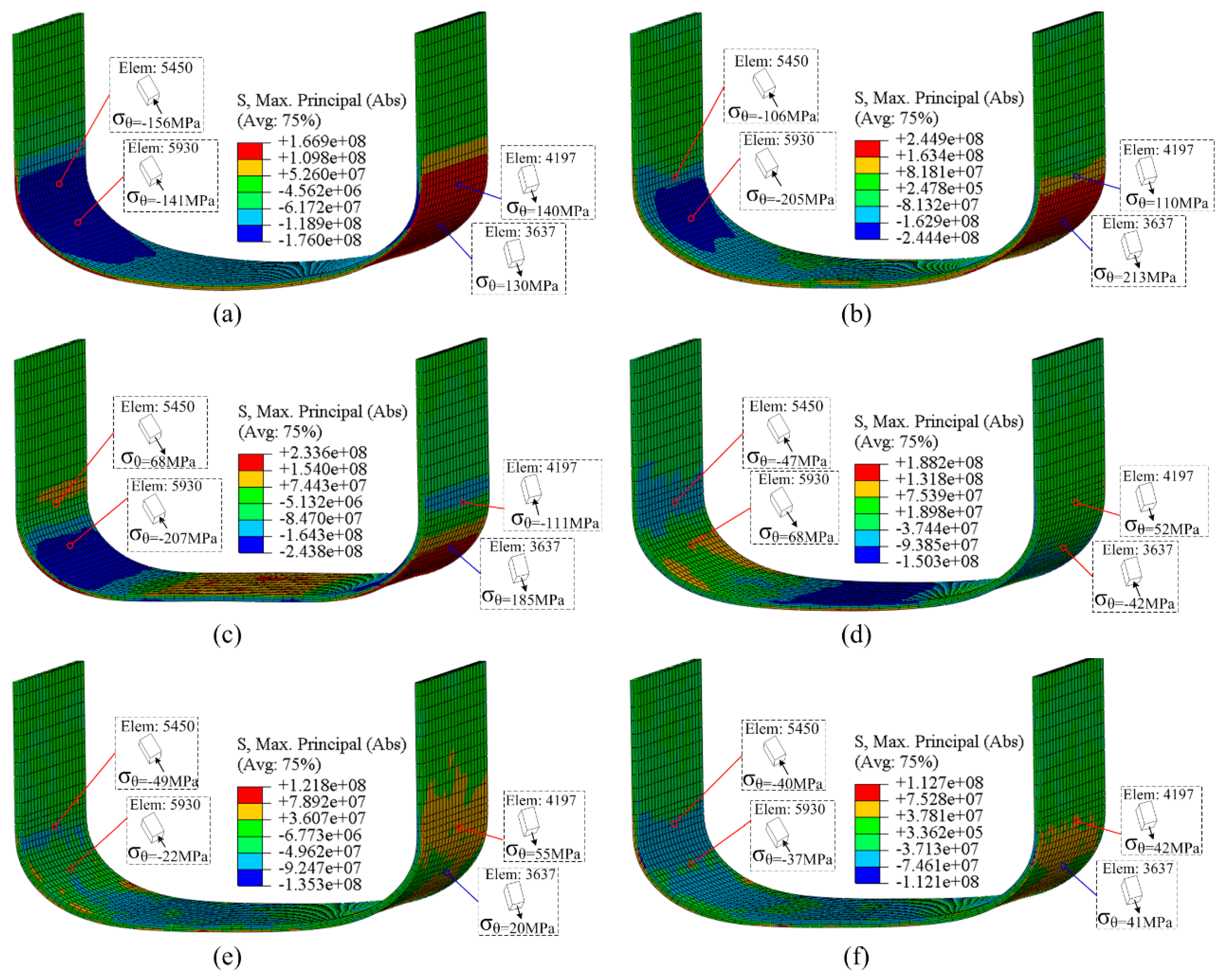
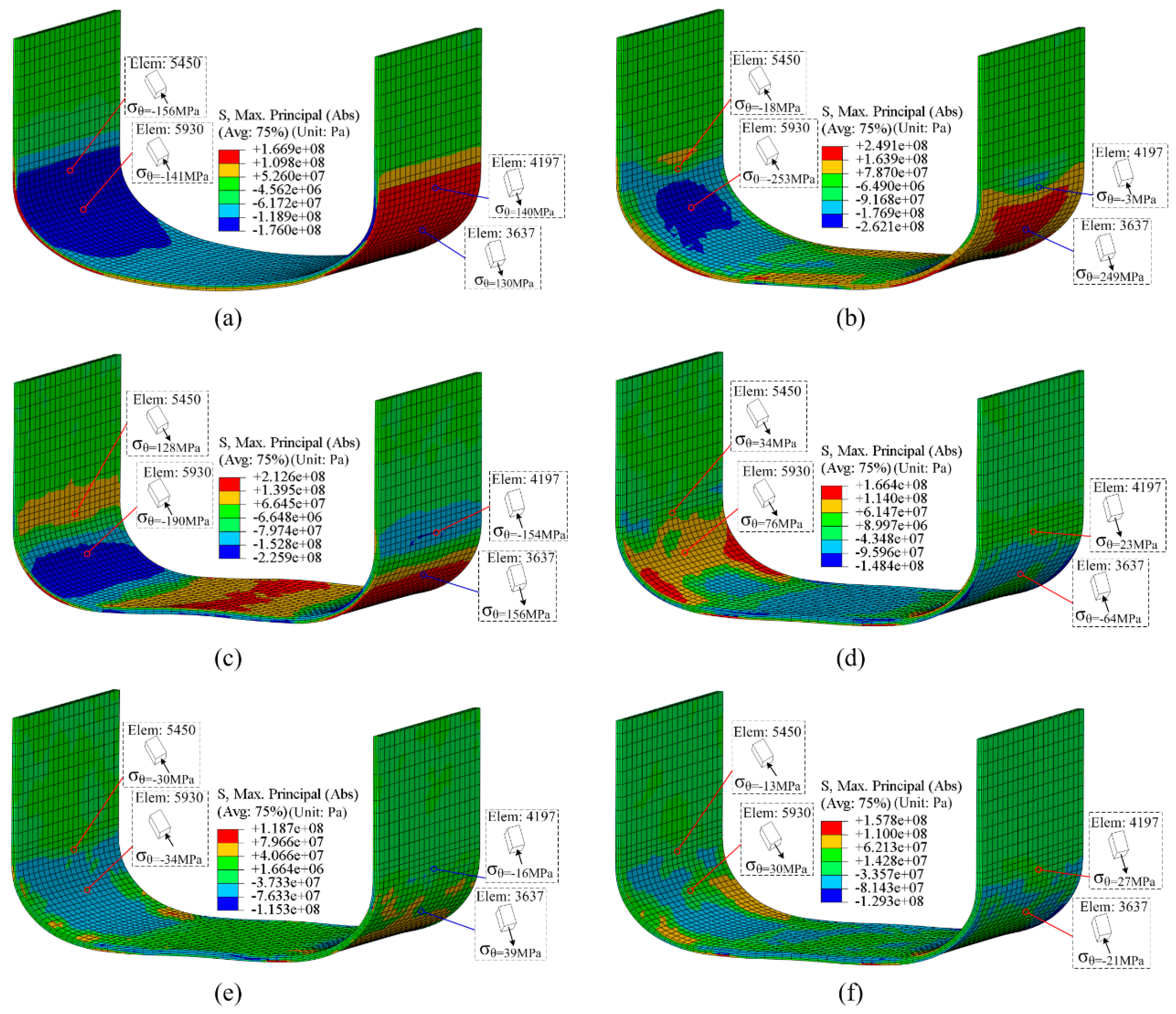
3.1. Discharge Voltage U = 1.5 kV

Figure 5 shows the shape deformation of sheet metal at different times for discharge voltage U = 1.5 kV. In order to facilitate the observation of different sheet regions deformed, the displacement of the sheet metal at the initial discharge time is defined as 0. When the coil is discharging, the material at the sheet corner region moves away from the punch. Thus, the contact area between the sheet and the die increases and the middle part of the sheet becomes flat during EMF. After the discharge time exceeds 1500 μs, the bottom of the sheet metal is separated from the die. At the time of 3000 μs, it can be considered that the sheet metal deformation is terminated.
Figure 6 shows the distribution of maximal principal stress in the sheet at different times for the discharge voltage U = 1.5 kV. In Figure 6a–d, the stress concentration area on sheet metal gradually moves towards the sheet metal center. From the time of 0–75 μs, the value of tangential stress at elements 5450 and 4197 decreases, while the tangential stress at elements 5930 and 3637 increases. From the time of 600–3000 μs, there are small tangential stresses at the corner region. Because the tangential compressed stress exists in the inner corner region and the tangential tensile stress exists in the outer corner region at 3000 μs, springback should occur.
Comparing the results of Figure 2 with Figure 6, the tangential stress on the sheet corner after EMF is smaller than after quasi-static stamping. The springback angle after EMF with 1.5 kV should be smaller than the one after stamping. Figure 7 shows the springback results after a coil discharge at 1.5 kV. The springback angle after coil discharge at 1.5 kV is about 4.9°.
Figure 8 shows the changes of three principal stresses over time at nodes 3694 and 7893. The position of the special nodes on elements is shown in Figure 8. The position of the special elements on the sheet is shown in Figure 6. At the discharge time of 0 μs, the values of three principal stresses are obtained by quasi-static stamping. When the discharge voltage is 1.5 kV, the three principal stresses at special nodes undergo disordered high frequency oscillation. At the end of the EMF process of 3000 μs, the tangential stresses at the two special nodes are obviously less than the one at the moment of 0 μs.

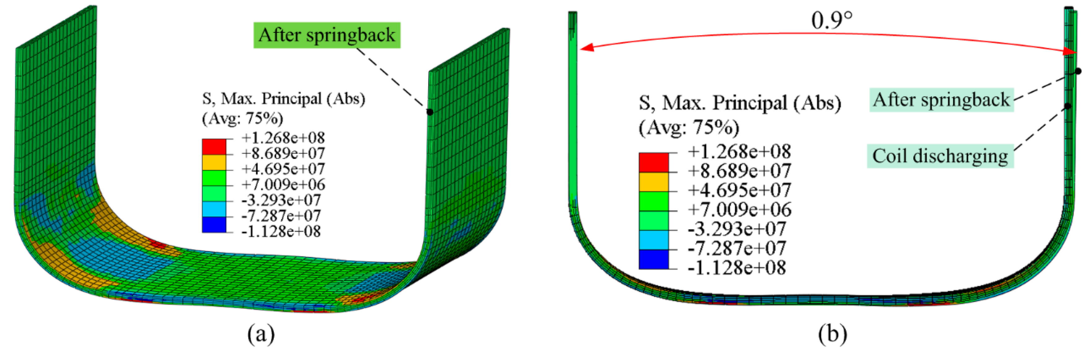
3.2. Discharge voltage U = 2 kV

Figure 9 shows the distribution of maximal principal stress on the sheet at different times when the discharge voltage U = 2 kV. In comparison with the results in Figure 6, the value of the tangential stress at elements 5450 and 4197 decreases more sharply, while the tangential stress at elements 5930 and 3637 increase more sharply with a higher discharge voltage from the time of 0 to 75 μs. At the time of 600 μs, tangential tensile stresses occurs at elements 5450 and 5930, positioned at the inner layer of the sheet corner. The direction of tangential stress for elements 5450 and 5930 is different from the results in Figure 2c and Figure 9d. At 3000 μs, both tangential compression stress and tensile stress exist on inner and outer layer of sheet corner. Thus, the springback angle could further decrease with 2 kV discharging, compared with the results of 1.5 kV discharging.
Figure 10 shows the springback after coil discharge at 2 kV; the springback angle after coil discharge at 2 kV is about 0.9°. In comparison with the results in Figure 2, Figure 7, and Figure 10, the springback angle after coil discharge decreases more sharply with a higher discharge voltage.

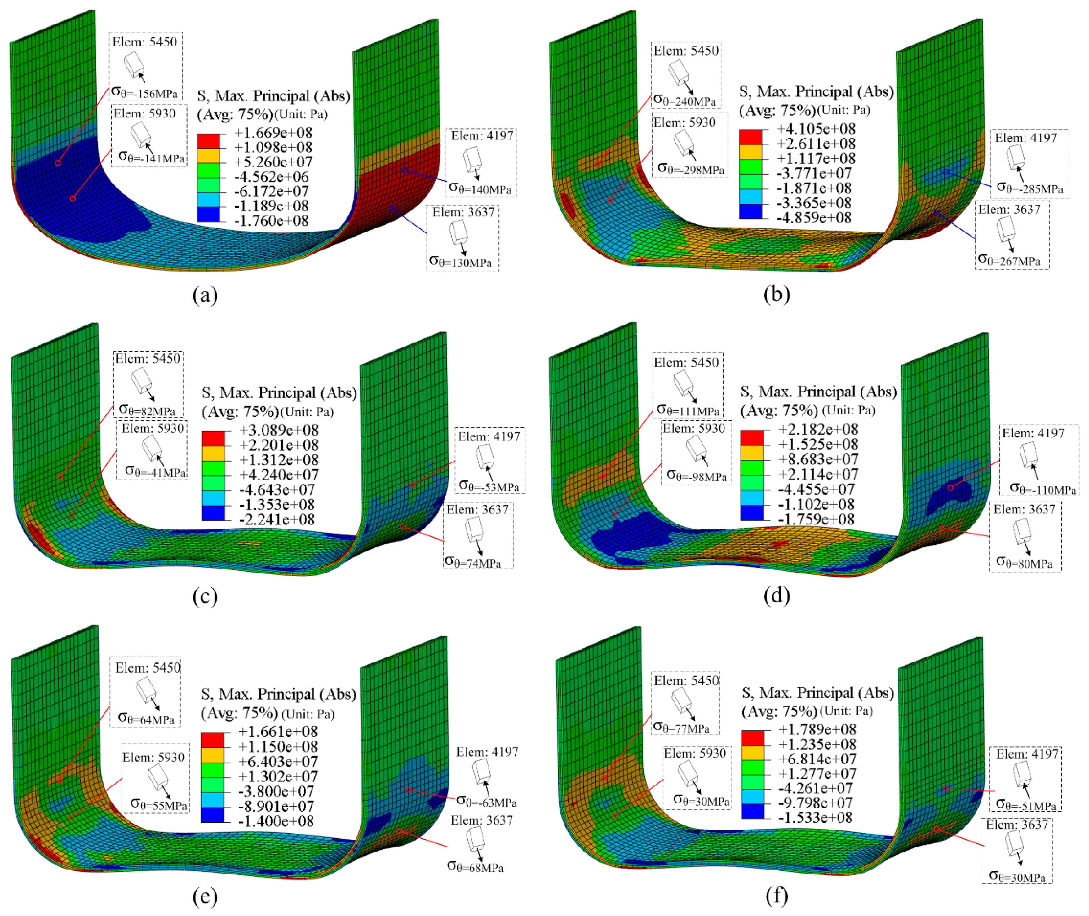
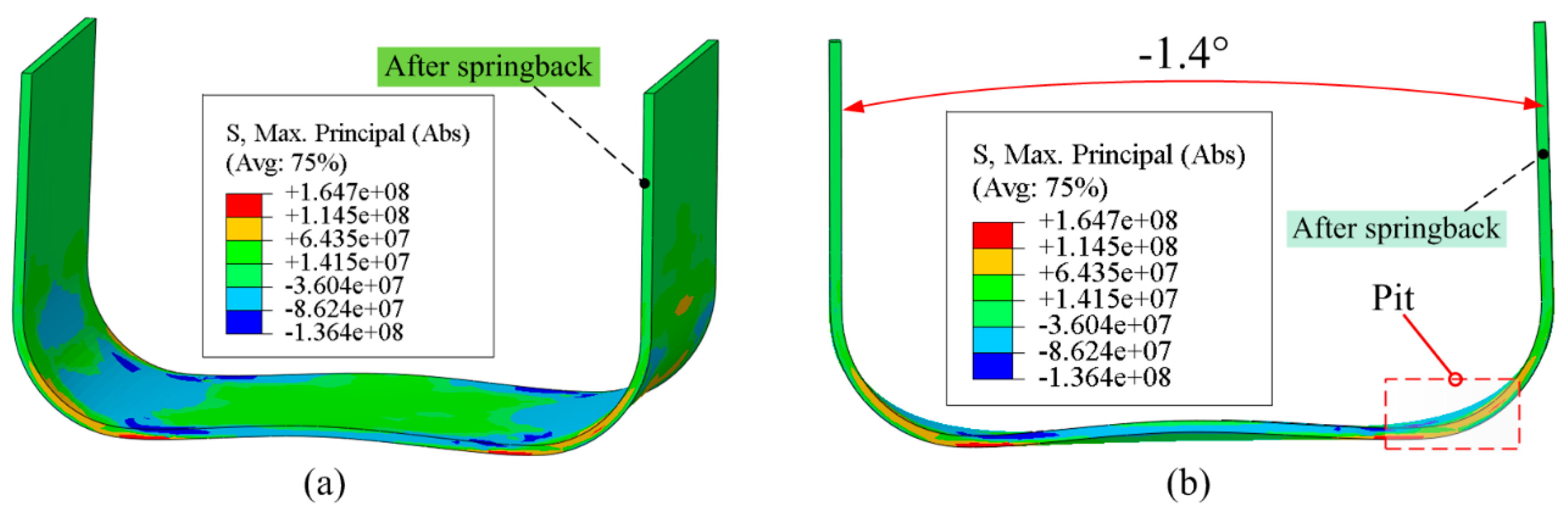
3.3. Discharge Voltage U = 3 kV

Figure 11 shows the distribution of maximal principal stress on the sheet at different times for the discharge voltage U = 3 kV. It is found that the two sides of the sheet metal width deform faster than the sheet center. This is because, a large induced current appears at the side of the sheet metal after coil discharge, and a larger induced current corresponds to a larger magnetic field force. Therefore, a pit appears at the sheet corner region after deformation, which reduces the deformation uniformity compared with 1.5 and 2 kV.
Figure 12 shows the springback results after a coil discharge at 3 kV. The springback angle after coil discharge at 3 kV is about −1.4°. However, a pit appears at the sheet corner region after springback, which causes the deformation uniformity to be reduced. The corner radius is not the same along the entire width of the sheet.

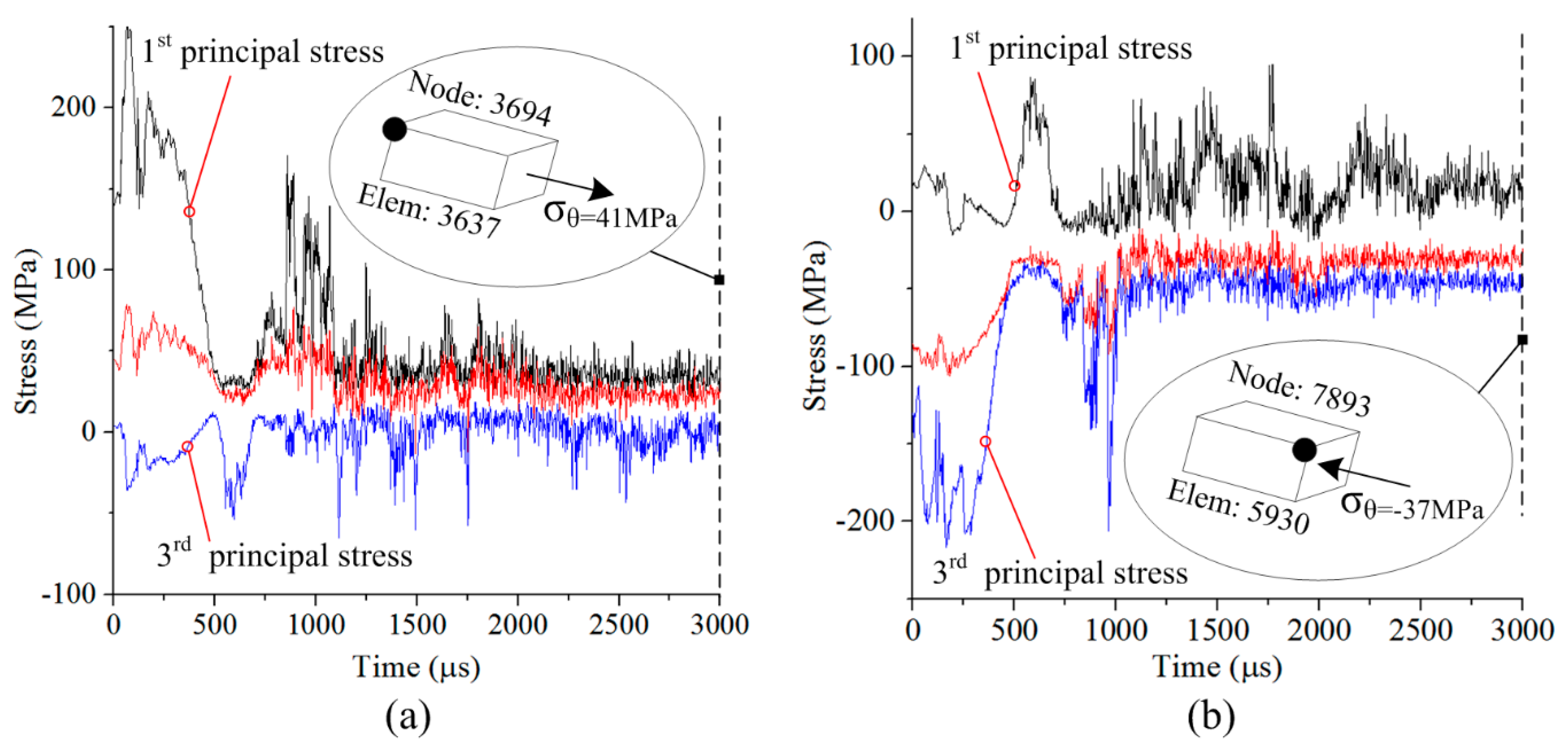
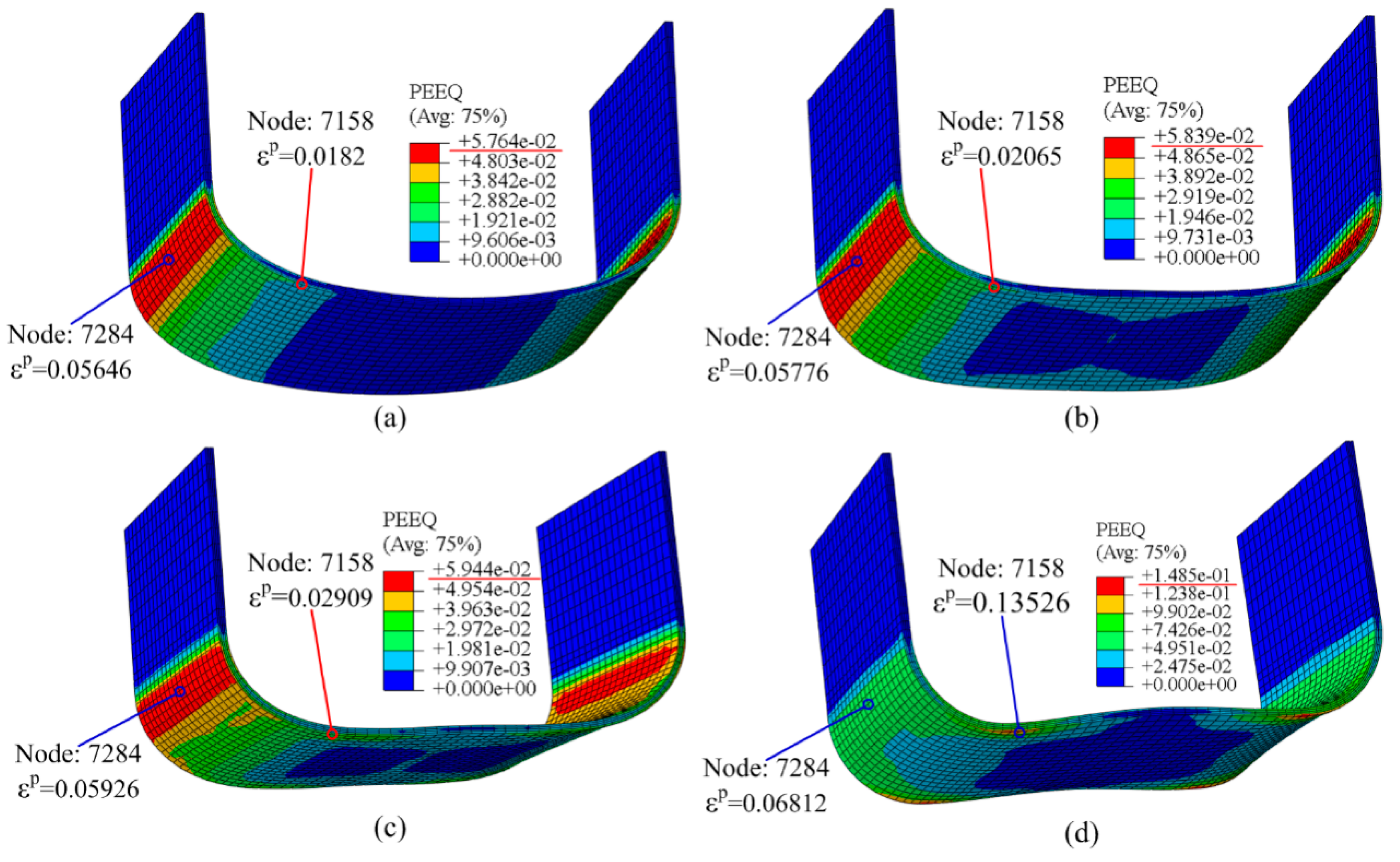
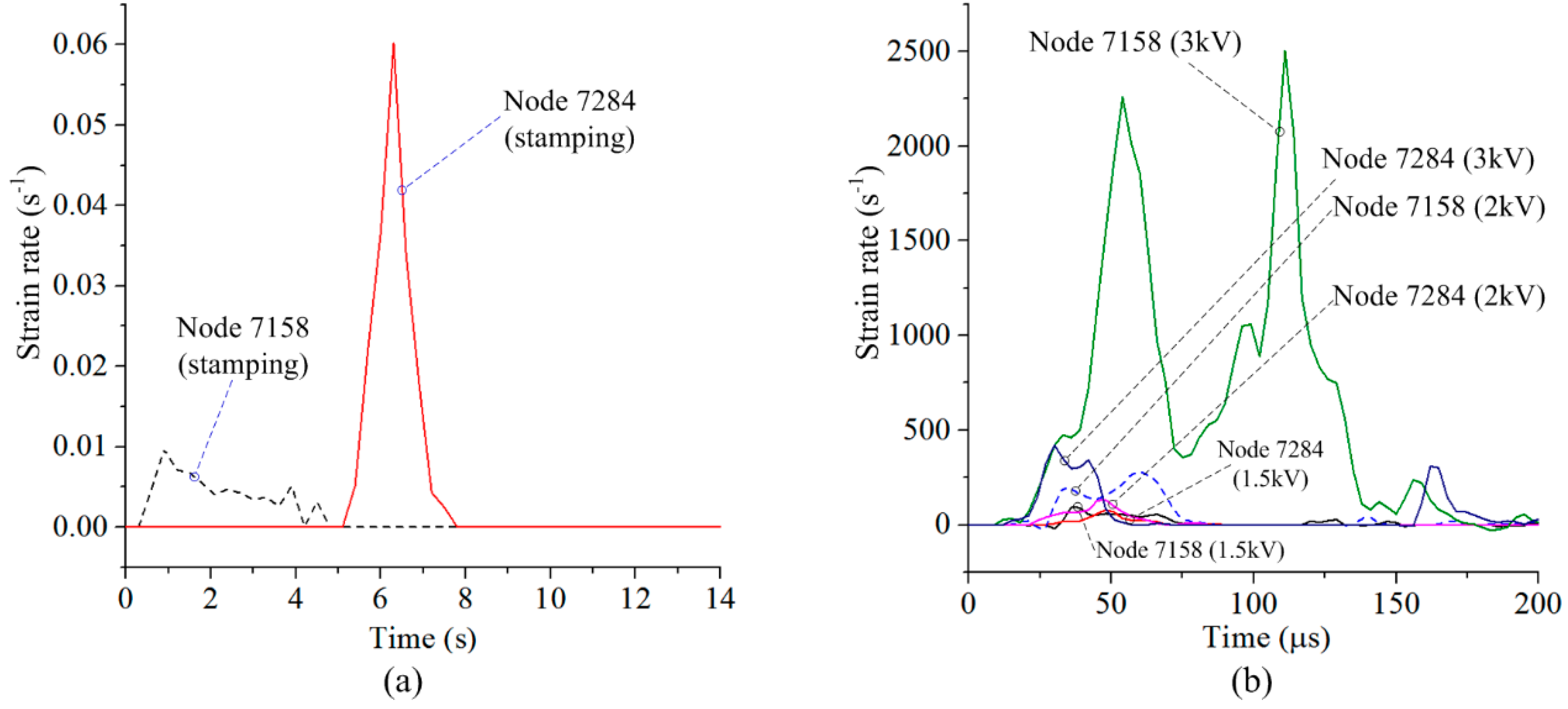
3.4. Plastic Strain and Strain Rate

Figure 13 shows the distribution of equivalent plastic strain on the sheet. Under the condition of quasi-static stamping, the plastic strain mainly occurs at the corner region of the sheet, and the plastic strain in the middle region of the sheet is close to zero. After the coil discharge, the maximum plastic strain on the sheet increases due to the sheet becoming re-deformed under the action of electromagnetic force. Plastic deformation occurs at the middle part of the sheet. In order to facilitate subsequent analysis, special nodes 7284 and 7158 were chosen. It can be found that the plastic strain of nodes 7284 and 7158 gradually increases as the discharge voltage increases.
Figure 14 shows the strain rate versus time for nodes 7158 and 7284. In the quasi-static stamping, the punch is assumed to bend the sheet at a speed of 2 mm/s. Thus, the maximum strain rates of nodes 7284 and 7158 are 0.06 and 0.01 s−1, respectively. If the coil is discharged at 1.5, 2 or 3 kV, the plastic strain at node 7284 is only slightly increased, while the strain rate at node 7284 is greatly increased. The maximum strain rate at node 7284 at 3 kV is 341 s−1. As shown in Figure 13, the plastic strain at node 7158 with 3 kV discharge is significantly increased compared to the quasi-static condition. This results in a significant increase in the strain rate at node 7158 after discharge, to a maximum of 2511 s−1.

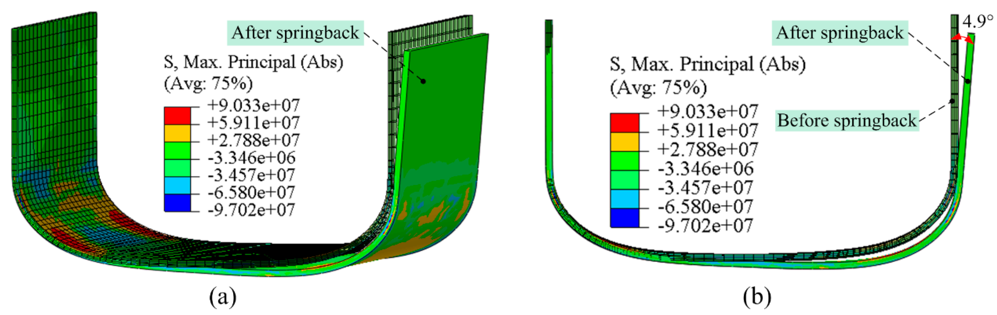
3.5. Simulation Verification

The changes in the angle after EMF are shown in Table 1. Both experimental data [11,12] and the simulation suggest that the method is accurate at predicting electromagnetically assisted bending. At 3 kV there exists a pit at the sheet corner region after springback, which coincides with the simulation results shown in Figure 12.

4. Conclusions

In this study, a 3D finite-element model (FEM) with U-shaped bending was developed using the ABAQUS and ANSYS software package. It can be concluded that:
(1)
The simulation results are in good agreement with the experimental results. It is proven that the simulation method is accurate at predicting the springback for quasi-static stamping and electromagnetically assisted bending.
(2)
After the coil discharges with 1.5 and 2 kV, the tangential stress on the sheet corner will be greatly reduced, and the springback will also be significantly reduced. If discharge voltage is 3 kV, the tangential stress distribution on the sheet corner region is more uneven and a higher plastic strain on the sheet. Thus, the springback can be further reduced at 3 kV. However, the deformation uniformity is reduced.

Author Contributions

The research was conceived by X.C. and Z.Z.; X.C. and Z.Z. planned and performed all the simulations; Z.Z. collected all data; Theoretical and experimental analysis were performed by H.Y., Q.C., and X.X.; The manuscript was reviewed by X.C. and H.Y., The manuscript was written by X.C.; with support from all co-authors.

Funding

This work was supported by the National Natural Science Foundation of China (Grant Nos. 51775563 and 51405173), Innovation Driven Program of Central South University (Grant number: 2019CX006), State Key Laboratory of Materials Processing and Die & Mould Technology, Huazhong University of Science and Technology (No. P2017-013) and the Project of State Key Laboratory of High Performance Complex Manufacturing, Central South University (ZZYJKT2017-03), Guangzhou Science and Technology Plan Project (201707010472) and The project was supported by Open Research Fund of State Key Laboratory of High Performance Complex Manufacturing, Central South University (No. Kfkt2018-02).

Conflicts of Interest

The authors declare no conflict of interest.

References

  1. Yan, Y.; Wang, H.B.; Wan, M. Prediction of stiffener buckling in press bend forming of integral panels. Trans. Nonfer. Met. Soc. China. 2011, 21, 2459–2465. [Google Scholar] [CrossRef]
  2. Wang, T.; Platts, M.J.; Wu, J. The optimisation of shot peen forming processes. J. Mater. Process. Technol. 2008, 206, 78–82. [Google Scholar] [CrossRef] [Green Version]
  3. Psyk, V.; Risch, D.; Kinsey, B.L.; Tekkaya, A.E.; Kleiner, M. Electromagneticforming—A review. J. Mater. Process. Technol. 2011, 211, 787–829. [Google Scholar] [CrossRef]
  4. Oliveira, D.A.; Worswick, M.J.; Finn, M. Electromagnetic forming of aluminum alloy sheet: Free-form and cavity fill experiments and model. J. Mater. Process. Technol. 2005, 170, 350–362. [Google Scholar] [CrossRef]
  5. Li, Z.G.; Li, N.; Jiang, H.W.; Xiong, Y.Y.; Liu, L. Deformation texture evolution of pure aluminum sheet under electromagnetic bulging. J. Alloy. Compd. 2014, 589, 164–173. [Google Scholar] [CrossRef]
  6. Xu, J.R.; Yu, H.P.; Cui, J.J.; Li, C.F. Formability of AZ31 magnesium alloy sheets during magnetic pulse bulging. Mater. Sci. Eng. A 2013, 569, 150–158. [Google Scholar]
  7. Guo, K.; Lei, X.P.; Zhan, M.; Tan, J.Q. Electromagnetic incremental forming of integral panel under different discharge conditions. J. Manuf. Process. 2017, 28, 373–382. [Google Scholar] [CrossRef]
  8. Xiong, W.R.; Wang, W.P.; Wan, M.; Li, X.J. Geometric issues in V-bending electromagnetic forming process of 2024-T3 aluminum alloy. J. Manuf. Process. 2015, 19, 171–182. [Google Scholar] [CrossRef]
  9. Kiliclar, Y.; Vladimirov, I.N.; Wulfinghoff, S.; Reese, S.; Demir, O.K.; Weddeling, C.; Tekkaya, A.E.; Engelhardt, M.; Klose, C.; Maier, H.J.; et al. Finite element analysis of combined forming process by means of rate dependent ductile damage modeling. Int. J. Mater. Form. 2017, 10, 73–84. [Google Scholar] [CrossRef]
  10. Shang, J.H. Electromagnetically Assisted Sheet Metal Stamping. Ph.D. Thesis, The Ohio State University, Columbus, OH, USA, 2006. [Google Scholar]
  11. Liu, D.H.; Zhou, W.H.; Li, C.F. Springback control and deformation analysis for electromagnetically assisted bending of U-shaped parts. Chin. J. Nonfer. Met. 2013, 23, 3075–3082. [Google Scholar]
  12. Sun, C. Deformation Analysis of U Shape Parts Formed by Electromagnetically Assisted Sheet Metal Bending. Master’s Thesis, Harbin Institute of Technology, Harbin, China, June 2009. [Google Scholar]
  13. Iriondo, E.; Gutiérrez, M.A.; González, B.; Alcaraz, J.L. Daehn GS. Electromagnetic impulse calibration of high strength sheet metal structures. J. Mater. Process. Technol. 2011, 211, 909–915. [Google Scholar] [CrossRef]
  14. Iriondo, E.; Alcaraz, J.L.; Daehn, G.S.; Gutiérrez, M.A.; Jimbert, P. Shape calibration of high strength metal sheets by electromagnetic forming. J. Manuf. Process. 2013, 15, 183–193. [Google Scholar] [CrossRef]
  15. Woodward, S.; Weddeling, C.; Daehn, G.; Psyk, V.; Carson, B.; Tekkaya, A.E. Agile production of sheet metal aviation components using disposable electromagnetic actuators. In Proceedings of the 4th International Conference on High Speed Forming, Columbus, OH, USA, 9 March 2010; pp. 35–46. [Google Scholar]
  16. Cui, X.H.; Mo, J.H.; Li, J.J.; Huang, L.; Zhu, Y.; Li, Z.W.; Zhong, K. Effect of second current pulse and different algorithms on simulation accuracy for electromagnetic sheet forming. Int. J. Adv. Manuf. Technol. 2013, 69, 1137–1146. [Google Scholar] [CrossRef]
  17. Cui, X.H.; Mo, J.H.; Li, J.J.; Xiao, X.T.; Zhou, B.; Fang, J.X. Large-scale sheet deformation process by electromagnetic incremental forming combined with stretch forming. J. Mater. Process. Technol. 2016, 237, 139–154. [Google Scholar] [CrossRef]
Figure 1. Simulation strategy for springback control by EMF.
Metals 09 00603 g001
Figure 2. Structure-field model. (a) Geometric dimension; (b) 2D view of stamping; (c) 3D view of stamping; (d) angle in 2D view after springback.
Metals 09 00603 g002
Figure 3. Field analysis of the (a) electromagnetic field model; (b) updated model of the sheet and the coil; and (c) induced current on the sheet metal.
Metals 09 00603 g003
Figure 4. Current through the coil as a function of time.
Metals 09 00603 g004
Figure 5. Distribution of displacement in the sheet for 1.5 kV at different times: (a) 0 μs, (b) 75 μs, (c) 300 μs, (d) 600 μs, (e) 1500 μs, and (f) 3000 μs.
Metals 09 00603 g005
Figure 6. Distribution of tangential stresses in the sheet for 1.5 kV at different times: (a) 0 μs, (b) 75 μs, (c) 300 μs, (d) 600 μs, (e) 1500 μs, and (f) 3000 μs.
Metals 09 00603 g006
Figure 7. Springback after coil discharge at 1.5 kV: (a) 3D view; (b) 2D view profile.
Metals 09 00603 g007
Figure 8. Stress changes at special nodes: (a) node 3694; (b) node 7893.
Metals 09 00603 g008
Figure 9. Distribution of tangential stresses in the sheet for 2 kV at different times: (a) 0 μs, (b) 75 μs, (c) 300 μs, (d) 600 μs, (e) 1500 μs, and (f) 3000 μs.
Metals 09 00603 g009
Figure 10. Springback after the coil discharge at 2 kV: (a) 3D view; (b) 2D view.
Metals 09 00603 g010
Figure 11. Distribution of tangential stresses in the sheet for 3 kV at different times: (a) 75 μs, (b) 150 μs, (c) 300 μs, (d) 600 μs, (e) 1500 μs, and (f) 3000 μs.
Metals 09 00603 g011
Figure 12. Springback after coil discharge at 3 kV: (a) 3D view; (b) 2D view.
Metals 09 00603 g012
Figure 13. Equivalent plastic strain. (a) Quasi-static stamping; (b) 1.5 kV; (c) 2 kV; (d) 3 kV.
Metals 09 00603 g013
Figure 14. Strain rate versus time for (a) quasi-static stamping, and (b) coil discharge with different voltages.
Metals 09 00603 g014
Table 1. Simulation and experiment.
Discharge Voltage01.5 kV2 kV3 kV
Experiment20.8°4.3°−0.2°
Simulation18.9°4.9°0.9°−1.4°

