Abstract
The coupled Finite Fracture Mechanics (FFM) criteria are applied to investigate the ductile failure initiation at blunt U-notched and V-notched plates under mode I loading conditions. The FFM approaches are based on the simultaneous fulfillment of the energy balance and a stress requirement, and they involve two material properties, namely the fracture toughness and the tensile strength. Whereas the former property is obtained directly from experiments, the latter is estimated through the Equivalent Material Concept (EMC). FFM results are presented in terms of the apparent generalized fracture toughness and compared with experimental data already published in the literature related to two different aluminium alloys, Al 7075-T6 and Al 6061-T6, respectively. It is shown that FFM predictions can be accurate even under moderate or large scale yielding regimes.
1. Introduction
It is well-assessed that brittle fracture initiation in notched structures can be described accurately by combining a linear elastic fracture analysis with an internal material length l. This framework is generally known as Finite Fracture Mechanics (FFM), underlying the fact that the provisional fracture is supposed to proceed through a finite crack extension, at least at crack initiation. Different criteria have been proposed [1] by imposing that either the average energy [2,3] or the punctual/average stress [1,3,4] at a finite distance l from the notch root are greater than the material properties, i.e., the fracture energy Gc (Gc KIc2, KIc being the fracture toughness) or the tensile strength σu, respectively. The crack advance l results to be a function of KIc and σu, and more in general it becomes a structural parameter in the case of coupled criteria, i.e., when the energy and stress conditions are coupled together [5,6]. It is worthwhile to mention that under the small scale yielding regime, the generalized stress intensity factor (GSIF, governing the asymptotic expansions of both the stress field and the SIF related to a virtual crack stemming from the notch tip providing the crack driving force) results to be the dominating failure parameter: Fracture can thus be supposed to take place when it reaches its critical value, also known as generalized (or notch) fracture toughness.
Undoubtedly, all the FFM approaches are highly sensitive to the material properties, which must be then estimated carefully. Whilst the fracture toughness can be obtained experimentally following the standard ASTM codes, the discussion is open when dealing with the tensile strength. As a matter of fact, the behaviour of plain specimens is strongly affected by the presence of micro-cracks/defects, and the experimental value of σu obtained by tensile testing hourglass-shape samples can be lower than the real one σ0. The ratio σ0/σu can vary sensibly from material to material. Taylor [1] observed by fitting the value of σ0 through the simple point stress criterion that the ratio σ0/σu approaches the unit value for ceramics, it is comprised between one and two for polymers, and can be sensibly larger (even up to eight) for metals. Of course, in this latter case, it is difficult to refer to σ0 as a tensile strength, and some attempts to provide a clear physical/mechanics were recently put forward [7]. It should be also mentioned that in order to avoid the problems raised when dealing with plain specimens, Seweryn [3,4] decided to test blunt notched samples where the root radius was large enough to provide a nearly constant stress field: The maximum tensile stress at the notch tip was estimated equal to σ0.
Since the work by Susmel and Taylor [8], the idea that the above criteria could be applied to deal also with ductile fracture has spread out through the Scientific Community. Susmel and Taylor [8], observing static failures in notched specimens made of a commercial cold-rolled low-carbon steel, found stress criterion predictions to be highly accurate, generally falling within an error interval of about 15%. The parameter σ0 was estimated through a fitting procedure on the stress criterion, namely through the intersection point of the failure stress fields for a blunt and a sharp notched structure. Finally, it was concluded that prediction accuracy slightly increased by using a numerical elasto-plastic analysis, but not so much to justify the huge computational effort.
Following the same approach and using the same stress criteria, analogous considerations were put forward after tensile testing U-notched samples made of Al 7075-T651 [9]. Indeed a slightly different approach was proposed in [10], where it was suggested, instead of working on the tensile strength, to calibrate the critical length when dealing with structural steels.
More recently, an extensive experimental campaign has been carried out to investigate the ductile fracture of U-notched and blunt V-notched plates [11,12,13,14] under mode I loading conditions. The above tests involved two aluminium alloys, Al 7075-T6 and Al 6061-T6, respectively: It was observed that Al 7075-T6 plates failed by moderate scale yielding, whereas Al 6061-T6 plates failed by large scale yielding.
Additionally, in this case, stress criteria were exploited to match experimental data, but σ0 was evaluated through the Equivalent Material Concept (EMC) theory proposed by Torabi [15]. Once the fracture toughness KIc is fixed, the EMC idea is to compare the behaviour of a ductile material with that of a virtual brittle material possessing a different tensile strength σ0. Its values are determined by considering identical values for the strain energy density (i.e., the area below the stress-strain curve) required by the ductile material under investigation and by the virtual brittle one. In formulae:
where σY is the yield strength, E is the Young’s modulus, K is the strain-hardening coefficient, n is the strain-hardening exponent, and εu is the true plastic strain at maximum load. Thus, differently from the previous approaches where σ0 was no more than a fitting parameter, according to EMC it recovers a precise physical meaning, and its value can be determined starting from the real experimental properties. More recently also the strain energy density (SED) criterion [2] has been exploited and applied to the experimental results as before [16,17].
The purpose of the present work is to investigate the mode I behaviour of blunt V-notched plates made of Al 7075-T6 and Al 6061-T6 [11,12,13,14] by combining the coupled FFM approaches and EMC. It is important to point out that, with respect to the stress criteria, coupled FFM approaches allow to remove some inconsistencies [6], their extension to complex geometries, such as interfacial cracks [18], results are more straightforward, and they provide close predictions to the Cohesive Zone Model once the constitutive law is defined ad-hoc [19,20,21]. Some recent applications involve the study of stable/unstable crack propagation from a circular hole [22,23], the extension to 3D crack propagation [24], and the study of crack patterns at bi-material interfaces [25,26].
2. FFM Criteria
The coupled FFM approaches are based on the hypothesis of a finite crack extension l and assume the simultaneous fulfillment of two conditions [5,6].
The first FFM condition establishes that the average energy available for a crack length increment l (evaluated by integrating the crack driving force G over l) is higher than the fracture energy . By referring to the blunt V-notch geometry reported in Figure 1 (ρ being the notch root radius), we have:
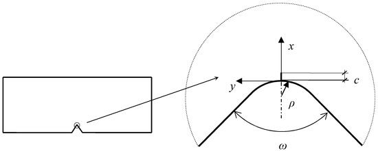
Figure 1.
Blunt V-notch geometry. The presence of a “virtual” crack of length c stemming from the notch tip is also depicted.
Equation (2), under mode I loading conditions, can be rewritten by means of Irwin’s relationship as:
where KI(c) is the SIF related to a crack of length c stemming from the notch root (Figure 1). An analytical relationship for the function KI(c) was proposed by Sapora et al. [27]
where is the GSIF referring to a V-notch with the same depth, and λ, β, m are functions only of the notch amplitude ω. Their values are reported in Table 1.

Table 1.
Values of different parameters compared to notch opening angle ω.
Furthermore, we have that:
and
Note that the original relationship proposed by Carpinteri et al. [28] did not include the parameter m, which was introduced later [27] to improve the prediction accuracy for low notch amplitudes. The presence of m in (4) does not prevent to fulfill the asymptotic limits for very short and very long (but still small in respect to the notch depth) cracks: Expected errors were estimated below 1% over the range 0 ≤ c/ρ ≤ 10 (0° ≤ ω ≤ 180°).
Introducing Equation (4) into Equation (3) yields:
where , and .
The second FFM condition involves the circumferential stress σy(x) together with the material tensile strength σu. It can be either a punctual requirement, for , which can be expressed as [5]
since the stress field is a monotonically decreasing function, or an average condition [6]
By assuming that the notch tip radius ρ is sufficiently small in respect to the notch depth, the stress field along the notch bisector could be expressed as [29]
The stress requirement can be easily rewritten by means of Equation (10) as
where the function f assumes different forms if the punctual condition (8) is considered
or if the average condition (9) is taken into account
Let us now suppose that failure takes place when the GSIF , reaches its critical conditions . Note that represents the apparent generalized fracture toughness (i.e., the generalized fracture toughness measured as if the V-notch was sharp): It depends on the root radius, differently from the GSIF, [25,26,27]. In critical conditions and for positive geometries [22], inequalities (7) and (11) become a system of two equations in two unknowns: The critical crack advancement lc, and the apparent generalized fracture toughness (i.e., the failure load).
From a more general point of view, by equaling expressions (7) and (11) in critical conditions with respect to , the problem can be recast in the following form:
Thus, for a specified material (KIc, σu) and a given geometry (ω, ρ), the critical crack advancement can be evaluated from the former equation in (14). This value must then be inserted into the latter equation to obtain the apparent generalized fracture toughness .
In the following section, Equation (14) will be implemented by distinguishing between “punctual FFM” (if h and f are defined via Equations (7) and (12), respectively) and “average FFM” (if h and f are defined via Equations (7) and (13), respectively). Note that the presence of the parameter m in Equation (7) prevents to get a closed form solution for the integrand function as in [28]: In the present analysis, the integral is computed numerically by applying an adaptive Simpson quadrature formula in a recursive way. The total computational cost related to solve Equation (14) through a simple MATLAB ® code is less than 5 s for each geometry, showing the potentiality of the present semi-analytical approach.
3. Comparison with Experimental Results
Let us now consider the results rising from the experimental campaign carried out in [11,12,13,14]. Tests involved: I) Two different aluminium alloys, namely Al 7075-T6 and Al 6061-T6; II) four notch amplitudes for each material: ω = 0°, 30°, 60°, and 90°; III) three different notch radii for each amplitude: ρ = 0.5, 1, and 2 mm for U-notches (ω = 0°); ρ = 1, 2, and 4 mm for other notch amplitudes. Details about the sample dimensions, the testing procedures, and the related results can be found in the papers quoted above.
In order to apply the FFM criteria described in the previous section, the values for the material properties are required. Whereas the fracture toughness KIc was derived experimentally, the tensile strength σu was obtained through the EMC by means of Equation (1) (and thus the parameter is re-termed as σ0, Section 1): Table 2 reports the values implemented in the present analysis taken from [12,13]. The ratio σ0/σu is equal to 3.16 for Al 7075-T6 and to 3.65 for Al 6061-T6, reflecting the fact failure of the samples made of Al 6061-T6 involved a larger amount of plasticity.
Table 2.
Material properties implemented in the present analysis.
Results in terms of the apparent generalized fracture toughness are presented in Figure 2, Figure 3, Figure 4 and Figure 5 as concerns ω = 0°, 30, 60, and 90°, respectively. It can be noted that punctual FFM [5] always provides higher predictions than average FFM [6], confirming the trend observed in past works (e.g., [25]). Indeed, for what concerns U-notched structures theoretical predictions by both criteria are always satisfactory (Figure 2), the maximum percentage discrepancy being nearly 20%. Punctual FFM results to be more accurate for Al 7075-T6 U-notched plates, whilst average FFM provides the best results for U-notched Al 6061-T6 plates: In this case, the discrepancy is less than 2.3%.
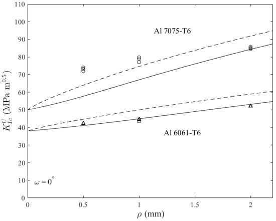
Figure 2.
U-notched structures (ω = 0°), apparent fracture toughness: Predictions by punctual FFM (dashed line) and average FFM (continuous line) related to experimental data on Al 7075-T6 plates (circles) and on Al 6061-T6 plates (triangles).
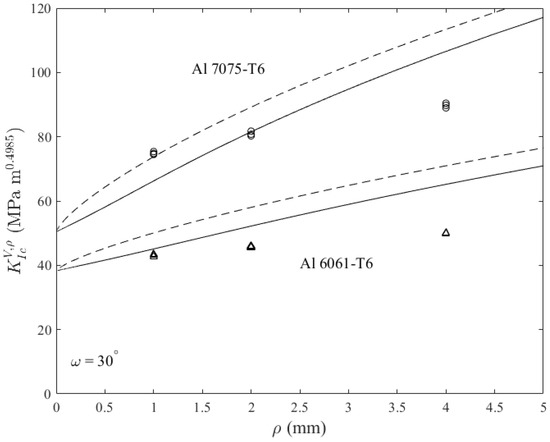
Figure 3.
Blunt V-notched structures (ω = 30°), apparent generalized fracture toughness: Predictions by punctual FFM (dashed line) and average FFM (continuous line) related to experimental data on Al 7075-T6 plates (circles) and on Al 6061-T6 plates (triangles).
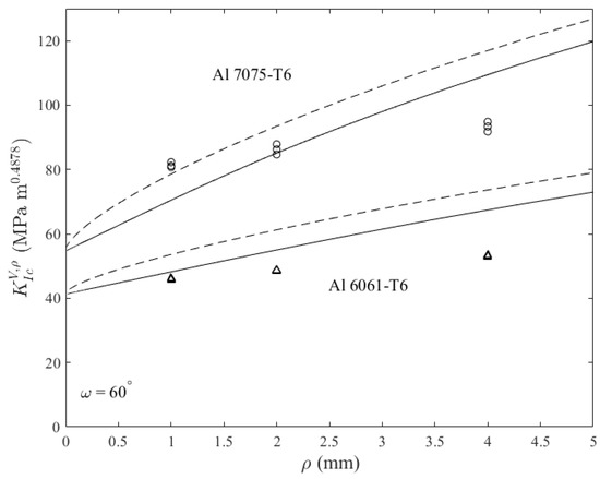
Figure 4.
Blunt V-notched structures (ω = 60°), apparent generalized fracture toughness: Predictions by punctual FFM (dashed line) and average FFM (continuous line) related to experimental data on Al 7075-T6 plates (circles) and on Al 6061-T6 plates (triangles).
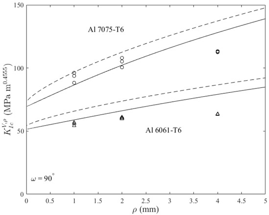
Figure 5.
Blunt V-notched structures (ω = 90°), apparent generalized fracture toughness: Predictions by punctual FFM (dashed line) and average FFM (continuous line) related to experimental data on Al 7075-T6 plates (circles) and on Al 6061-T6 plates (triangles).
For blunt V-notches (Figure 3, Figure 4 and Figure 5), the following considerations hold: (i) The average FFM generally provides the most accurate predictions; (ii) for Al 7075-T6 notched plates, the maximum discrepancy between the average FFM results and experimental data is always below 20%, the maximum discrepancy being observed for large radii; (iii) for Al 6061-T6 notched samples, theoretical predictions are generally less accurate, and they always overestimate the experimental data. The accuracy decreases with the radius, but for this material the discrepancy is much higher for the largest radius (ρ = 4 mm), exceeding always 20%, and reaching 30% for ω = 30°. The discrepancy related to the punctual FFM is significantly higher.
The situation for what concerns the percentage discrepancy between experimental results and average FFM predictions is summarized in Figure 6. In order to explain the higher deviation observed for Al 6061-T6 notched alloys with large radii, it should be said that first of all the precision of the asymptotic expansions (4) and (10) decreases as larger radii are considered. Anyway, this does not explain a discrepancy of 30% and the best accuracy of predictions for Al 7075-T6 plates, which possess exactly the same geometry. Thus, it can be supposed that some plastic phenomena took place during the failure mechanism affecting significantly the failure load. In other words, as ρ increases involving higher failure loads, the level of constraint can reduce as plastic zones become larger. This phenomenon is more pronounced for Al 6061-T6 structures, where a large scale yielding was observed, than for Al 7075-T6 plates which failed under moderate scale yielding [11,12,13,14]. Ductility is associated to complex failure mechanisms, which the present coupled FFM-EMC model (as well as other approaches recently proposed [8,9,10,11,12,13,14,15,16,17]) simply neglects.
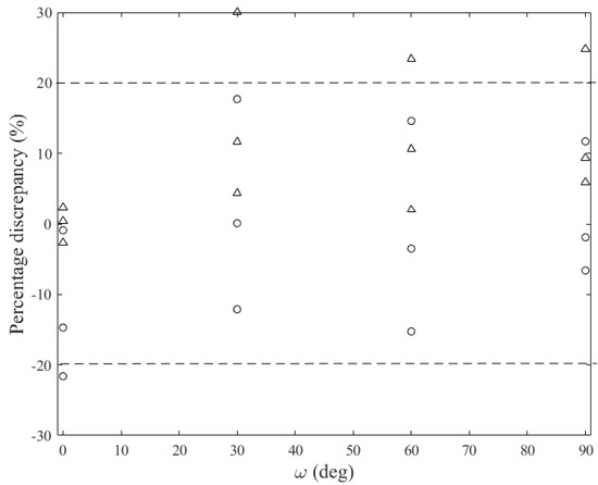
Figure 6.
Average FFM predictions: Percentage discrepancy with respect to experimental data referring to blunt V-notched structures made of Al 7075-T6 (circles), and made of Al 6061-T6 (triangles).
Finally, the average FFM diagrams of the apparent generalized fracture toughness and of the critical crack extension compared to the root radius are reported in Figure 7. In order to get dimensionless quantities, the well-known Irwin’s length is introduced. From Table 2, it follows that lch ≈ 0.73 mm for Al7075-T6, and lch ≈ 1.3 mm for Al6061-T6. It can be seen that the apparent generalized fracture toughness increases as the radius increases and/or the angle decreases. Thus, the cracked configuration is the most affected one by the presence of a radius ρ ≠ 0. As concerns the crack advance lc, it results a function of the material (through lch) and of the radius, tending to 2/(π·1.122) as ρ tends to infinite (smooth elements): From Figure 7 it can be seen that the values related to the crack case (ω = 0°) are the lowest ones for non-negligible radii. The analytical expressions for and lc when ρ = 0 (sharp case) can be found in [6].
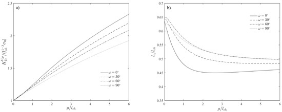
Figure 7.
Average FFM: Dimensionless apparent generalized fracture toughness (a) and dimensionless critical crack extension (b) compared to dimensionless notch root radius.
4. Conclusions
It is consolidated that in order to describe the failure mechanisms of ductile structures, an elasto-plastic finite element analysis has to be carried out. Nevertheless, this procedure generally requires huge computational efforts, and it may not be efficient from an engineer point of view. In this work, in the spirit of the previous papers [12,16], the coupled FFM approaches proposed by Leguillon [5] and Carpinteri et al. [6] are implemented to evaluate the mode I failure load of blunted V-notched samples made of two different materials, Al 7075-T6 and Al 6061-T6. By estimating the tensile strength through the EMC put forward by Torabi [15], it is found that FFM predictions are generally in good agreement with experimental results for Al 7075-T6, especially as regards the average criterion [6]. On the other hand, for Al 6061-T6, FFM results always overestimate the experimental data, becoming mediocre for large radii. In this case, the present coupled FFM-EMC formulation is not able to catch appropriately the effect of the large amount of plasticity involved in the failure mechanisms. Indeed, the EMC approach is formulated based on the standard stress-strain curve of the un-notched specimen, and it does not consider the local plasticity around the notch. Future work will consist of investigating more in details this framework to verify the accuracy of the coupled FFM-EMC model, calibrating its efficiency on the ductility of the structural behavior.
Author Contributions
All the authors conceived the idea of the research and contributed equally to the analysis tools; A.S. wrote the paper.
Funding
This research received no external funding.
Conflicts of Interest
The authors declare no conflict of interest.
References
- Taylor, D. The Theory of Critical Distances: A New Perspective in Fracture Mechanics; Elsevier: Oxford, UK, 2006. [Google Scholar]
- Lazzarin, P.; Zambardi, R. A Finite-volume-energy based approach to predict the static and fatigue behaviour of components with sharp V-shaped notches. Int. J. Fract. 2002, 112, 275–298. [Google Scholar] [CrossRef]
- Seweryn, A.; Lukaszewicz, A. Verification of brittle fracture criteria for elements with V-shaped notches. Engng. Fract. Mech. 2002, 69, 1487–1510. [Google Scholar] [CrossRef]
- Seweryn, A. Brittle fracture criterion for structures with sharp notches. Eng. Fract. Mech. 1994, 47, 673–681. [Google Scholar] [CrossRef]
- Leguillon, D. Strength or toughness? A criterion for crack onset at a notch. Eur. J. Mech. A/Solids 2002, 21, 61–72. [Google Scholar] [CrossRef]
- Carpinteri, A.; Cornetti, P.; Pugno, N.; Sapora, A.; Taylor, D. Generalized fracture toughness for specimens with re-entrant corners: Experiments vs. theoretical predictions. Struct. Eng. Mech. 2009, 32, 609–620. [Google Scholar] [CrossRef]
- Sapora, A.; Firrao, D. Finite fracture mechanics predictions on the apparent fracture toughness of as-quenched Charpy V-type AISI 4340 steel specimens. Fatigue Fract. Eng. Mater. Struct. 2017, 40, 949–958. [Google Scholar] [CrossRef]
- Susmel, L.; Taylor, D. On the use of the theory of critical distances to predict static failures in ductile metallic materials containing different geometrical features. Eng. Fract. Mech. 2008, 75, 4410–4421. [Google Scholar] [CrossRef]
- Madrazo, V.; Cicero, S.; Carrascal, I.A. On the Point Method and the Line Method notch effect predictions in Al7075-T651. Eng. Fract. Mech. 2012, 79, 363–379. [Google Scholar] [CrossRef]
- Cicero, S.; Fuentes, J.D.; Procopio, I.; Madrazo, V.; González, P. Critical distance default values for structural steels and a simple formulation to estimate the apparent fracture toughness in U-notched conditions. Metals 2018, 8, 871. [Google Scholar] [CrossRef]
- Torabi, A.R.; Alaei, M. Mixed-mode ductile failure analysis of V-notched Al 7075-T6 thin sheets. Eng. Fract. Mech. 2015, 150, 70–95. [Google Scholar] [CrossRef]
- Torabi, A.R.; Habibi, R.; Hosseini, B.M. On the ability of the Equivalent Material Concept in predicting ductile failure of U-notches under moderate- and large-scale yielding conditions. Phys. Mesomech. 2015, 18, 337–347. [Google Scholar] [CrossRef]
- Torabi, A.R.; Alaei, M. Application of the equivalent material concept to ductile failure prediction of blunt V-notches encountering moderate-scale yielding. Int. J. Damage Mech. 2016, 25, 853–877. [Google Scholar] [CrossRef]
- Torabi, A.R.; Keshavarzian, M. Tensile crack initiation from a blunt V-notch border in ductile plates in the presence of large plasticity at the notch vicinity. Int. J. Terraspace Sci. Eng. 2016, 8, 93–101. [Google Scholar]
- Torabi, A.R. Estimation of tensile load-bearing capacity of ductile metallic materials weakened by a V-notch: The equivalent material concept. Mater. Sci. Eng. A 2012, 536, 249–255. [Google Scholar] [CrossRef]
- Torabi, A.R.; Berto, F.; Campagnolo, A. Elastic-plastic fracture analysis of notched Al 7075-T6 plates by means of the local energy combined with the equivalent material concept. Phys. Mesomech. 2016, 19, 204–214. [Google Scholar] [CrossRef]
- Fuentes, J.D.; Cicero, S.; Berto, F.; Torabi, A.R.; Madrazo, V.; Azizi, P. Estimation of Fracture Loads in AL7075-T651 Notched Specimens Using the Equivalent Material Concept Combined with the Strain Energy Density Criterion and with the Theory of Critical Distances. Metals 2018, 8, 87. [Google Scholar] [CrossRef]
- Muñoz-Reja, M.; Távara, L.; Mantič, V.; Cornetti, P. Crack onset and propagation at fibre–matrix elastic interfaces under biaxial loading using finite fracture mechanics. Compos. Part. A 2016, 82, 267–278. [Google Scholar] [CrossRef]
- Cornetti, P.; Sapora, A.; Carpinteri, A. Short cracks and V-notches: Finite Fracture Mechanics vs. Cohesive Crack Model. Eng. Fract. Mech. 2016, 168, 2–12. [Google Scholar] [CrossRef]
- Cornetti, P.; Muñoz-Reja, M.; Sapora, A.; Carpinteri, A. Finite fracture mechanics and cohesive crack model: Weight functions vs. cohesive laws. Int. J. Solid Struct. 2019, 156–157, 126–136. [Google Scholar] [CrossRef]
- Doitrand, A.; Estevez, R.; Leguillon, D. Comparison between cohesive zone and coupled criterion modeling of crack initiation in rhombus hole specimens under quasi-static compression. Theor. Appl. Fract. Mech. 2019, 99, 51–59. [Google Scholar] [CrossRef]
- Felger, J.; Stein, N.; Becker, W. Mixed-mode fracture in open-hole composite plates of finite-width: An asymptotic coupled stress and energy approach. Int. J. Solid. Struct. 2017, 122–123, 14–24. [Google Scholar] [CrossRef]
- Sapora, A.; Cornetti, P. Crack onset and propagation stability from a circular hole under biaxial loading. Int. J. Fract. 2019, 214, 97–104. [Google Scholar] [CrossRef]
- Doitrand, A.; Leguillon, D. 3D application of the coupled criterion to crack initiation prediction in epoxy/aluminum specimens under four point bending. Int. J. Solids Struct. 2018, 143, 175–182. [Google Scholar] [CrossRef]
- Stein, N.; Weißgraeber, P.; Becker, W. A model for brittle failure in adhesive lap joints of arbitrary joint configuration. Compos. Struct. 2015, 133, 707–718. [Google Scholar] [CrossRef]
- Felger, J.; Rosendahl, P.L.; Leguillon, D.; Becker, W. Predicting crack patterns at bi-material junctions: A coupled stress and energy approach. Int. J. Solids Struct. 2019, 164, 191–201. [Google Scholar] [CrossRef]
- Sapora, A.; Cornetti, P.; Carpinteri, A. Cracks at rounded V-notch tips: An analytical expression for the stress intensity factor. Int. J. Fract. 2014, 187, 285–291. [Google Scholar] [CrossRef]
- Carpinteri, A.; Cornetti, P.; Sapora, A. Brittle failures at rounded V-notches: A finite fracture mechanics approach. Int. J. Fract. 2011, 172, 1–8. [Google Scholar] [CrossRef]
- Filippi, S.; Lazzarin, P.; Tovo, R. Developments of some explicit formulas useful to describe elastic stress fields ahead of notches in plates. Int. J. Solid. Struct. 2002, 39, 4543–4565. [Google Scholar] [CrossRef]


© 2019 by the authors. Licensee MDPI, Basel, Switzerland. This article is an open access article distributed under the terms and conditions of the Creative Commons Attribution (CC BY) license (http://creativecommons.org/licenses/by/4.0/).