Abstract
Aluminum Foam Sandwich panels were fabricated via liquid diffusion welding and glue adhesive methods. The Microstructure of the Aluminum Foam Sandwich joints were analyzed by Optical Microscopy, Scanning Electron Microscopy, and Energy Dispersive Spectroscopy. The metallurgical joints of Aluminum Foam Sandwich panels are compact, uniform and the chemical compositions in the diffusion transitional zone are continuous, so well metallurgy bonding between Aluminum face sheet and foam core was obtained. The joining strength of an Aluminum Foam Sandwich was evaluated by standard peel strength test and the metallurgical joint Aluminum Foam Sandwich panels had a higher peel strength. Moreover, a three-point bending fatigue test was conducted to study the flexural fatigue behavior of Aluminum Foam Sandwich panels. The metallurgical joint panels have a higher fatigue limit than the adhesive joining sandwich. Their fatigue fracture mode are completely different, the failure mode of the metallurgical joint is faced fatigue; the failure mode for the adhesive joint is debonding. Therefore, the higher joining strength leads to a longer fatigue life.
1. Introduction
Metallic foams, especially Aluminum foams (AF), have recently received attention because of their outstanding physical and chemical properties, including low density, high specific strength, impacting energy absorption, sound absorption, flame resistance and electromagnetic shield effectiveness [1,2,3,4,5,6,7,8]. Due to these aforementioned capabilities, metal foams can be used for many industrial applications such as aerospace, marine, railway, automotive and construction [9,10,11].
Aluminum Foam Sandwich (AFS) is a special class of composites materials which is widely used for panels, shells, tubes, crash protection devices and lightweight structures [12,13]. It is fabricated by sandwiching a thick AF as core material between two thin alloy sheets as facing sheets. With this sandwich structure, the AFS can provide specific strength, better dimensional stability, improved damping and acoustic insulation properties compared with the simply AF [14,15], as the core foam bears shear load meanwhile the face sheets carry an axial load and resist against bending [16].
Different joining techniques have been developed to join the AF core and facing sheets. Though adhesive is the most common method with low cost and simple operation [17], adhesive AFS has some drawbacks such as low joining strength and low-temperature resistance. In order to improve the joining strength and temperature resistance, metallurgical joining techniques such as casting, brazing [18] and soldering [19] are developed. Besides these traditional techniques, some other joining techniques based on metallurgical joining also have been proposed and investigated feasibility. Tungsten inert gas welding is a welding method for generating electric arc from activating tungsten or pure tungsten with inert gas to protect the manufacturing environment. This method has the benefits of good operability and low cost [20]. The Fluxless soldering technique, with a filling material SnAg4Ti working at 220–229 °C, can make the solder spread under the Oxide layer of the metal and completely wet the surface of the metal substrate. Then, the Oxide layer around the molten solder is removed mechanically, and the atoms of the solder and the substrate are closely joint [21,22]. Besides, metal glass brazing is also promoted to be a potential method with the soldering material of amorphous alloy [23]. Moreover, the sandwich and foam filled tubes made of Aluminum alloys could be fabricated by powder metallurgy method. The joining between the metal foams and the tubes or sheet are achieved during the formation of the liquid metallic foam, promoting a metallic bonding without any joining step. Results have demonstrated that the thermal treatment that is submitted to these tubes or sheets at high temperatures during the foam formation is beneficial to obtain a predictable and stable mechanical behavior of the resulting in-situ foam structures [24]. The ductility of these structures increases, leading to an efficient crashworthiness without the formation of cracks and abrupt failure when subjected to compressive and bending loads.
Among the metallurgical joining techniques, diffusion welding technique is commonly applied to prepare metals and complex structures. AFS panel prepared via this method has good mechanical properties because the metal microstructures of the core substrate and the face panels on the interface are compact and continuous. Kitazono et al. [25] studied the diffusion welding technique for closed-cell Al foam, and suggested that in the process of joint formation, the compressive stress is strong enough to break the Oxide film on the contacting surface, which reduces defects and promotes the diffusion of Al atom. Bangash et al. [26] have investigated the joining area of AF core to Al alloy sheets with Zn-based joining material and found that in the joining area, the presence of Al rich and Zn rich phases confirm the diffusion, ensuring strong metallurgical joining. They indicated that the joining process can easily be automated in a continuous furnace, guaranteeing high productivity, reproducibility and cheap industrial cost. However, they do not focus on the manufacture of large size AFS panels, which is one of the purposes of this paper.
In this paper, AFS beams were prepared by a specially designed method via a liquid diffusion welding process, which achieved a high strength joining between the AF core and face sheets. The fatigue behavior under three-point bending cyclic load is investigated. The effects of joining strength to fatigue behavior is analyzed, and fatigue fracture characteristics are discussed as well.
2. Materials and Experimental Methods
Aluminum alloy (AA)-5056 (Al 94.8% + Mg 4.5% + Fe 0.4% + Si 0.3%) plate (density 2.7 g/cm3), 1.0 mm thick, was selected to be the face sheet material for AFS. A lightweight, non-flammable eco-friendly closed-cell pure AF plate (average cell size 7 mm, average density 0.4 g/cm3, porosity 85%), 25 cm thick, produced by Yuantaida, Sichuan, China, was used as the core material. For the soldering material, Zn + 10% Al (Zn-10Al), with the liquid-solid phase transition temperature of 426.5 °C and 380.0 °C, was chosen to be the joint alloy because of its proper molten range of the Zinc-Aluminum binary alloy, good mechanical properties and wetting properties to the Aluminum alloy substrate. It was made from pressure cast 3# Zinc alloy (Zn 95.7% + Al 4.3%) and industrial pure Aluminum (Al ≥99.5%) by ourselves.
The Al alloy sheet and AF plate were all cut off in pieces of length 300 mm, width 50 mm, thickness 1 mm (sheet) and 25 mm (AF). The length-thickness ratio of the foam core referred to ASTM C393 [27]. The joining surfaces of the AF core and sheets were abraded with 200 mesh SiC paper in order to clean the Al Oxide and facilitate the metal joining process. Then the surfaces were cleaned with alcohol in an ultrasonic bath for 5 min.
The joining surfaces of AF core and face sheets were put into the melting solder bath about 450 °C for hot-dip coating for 50 s to form the joining alloy on the joining surfaces. Finally, the pre-coated AF core and sheets were jointed by a heat press process assisted with ultrasonic vibration 1 min to establish the optimal soldering parameters and achieve high joining strength. During the heat press process, induction heating equipment was employed to heat the sample up to 430 °C to remelt the solder coating.
For comparison purposes, the adhesive joining AFS panels were also fabricated by a heat compress method at 80 °C for 5 min with aerial adhesive film as joining glue. The macromorphology of two kinds of AFS panels from different manufacturing processes are shown in Figure 1.
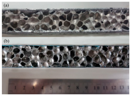
Figure 1.
Two kinds of AFS (Aluminum Foam Sandwich) panels from different manufacturing process (a) metallurgical joining (b) adhesive joining.
The AFS samples made for the mechanical tests were 300 mm long, 50 mm wide and 27 mm in thickness. Peel strength test was carried out by WDW-10 universal testing machine (Loading speed 25 mm/min) to test the joining strength of the two kinds of AFS samples according to the GB T1457-2005 [28]. Three-point bending fatigue test was carried out by MTS-809 fatigue test machine with the self-made fixture (Span length 200 mm), as shown in Figure 2, according to the ASTM C393 [27]. The AFS samples were tested at loading ratios R = −0.1, cycle frequency C = 7 Hz. A digital camera was used to record the fracture process to describe the fatigue behavior.
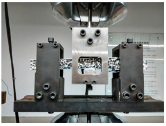
Figure 2.
Loading diagram of sample and fixture for fatigue test.
3. Results and Discussion
3.1. Microstructure
Figure 3 shows the two kinds of AFS joining interface microstructure. As shown in Figure 3a,b, the seam of metallurgical joint is a soldering Zn-Al alloy which have a typical eutectic structure. α-Al dendrites nucleated on the substrate surfaces of the Al sheet and foam core and grew into the Zn-Al alloy fusion area. This indicates that the molten ZnAl alloy have good wettability on the substrate surface and the interfaces of the ZnAl joining alloy and the substrates are intimate. Furthermore, the fusion is compact and continuous without any obvious macroscopic defects. Figure 3c,d present that the joint interface of the adhesive AFS sample is a typical physical joint with many obvious defects such as holes and irregular inclusions, which might be formed during the adhering process. The air between Al alloy sheets and Al foam could not be all pulled out, and the remain air in the adhesive might form the air holes when adhesive melts. Moreover, during the melting and remodeling process, the thermoplastic glue film would shrink and also form hole defects. The final result is that the physical joint is irregular and the connection between adhesive and substrates might be not tight, which lead to poor strength of the adhesive joint.
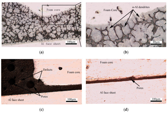
Figure 3.
Optical microscope images of AFS joining parts (a,b) Metallurgical joining (c,d) Adhesive joining.
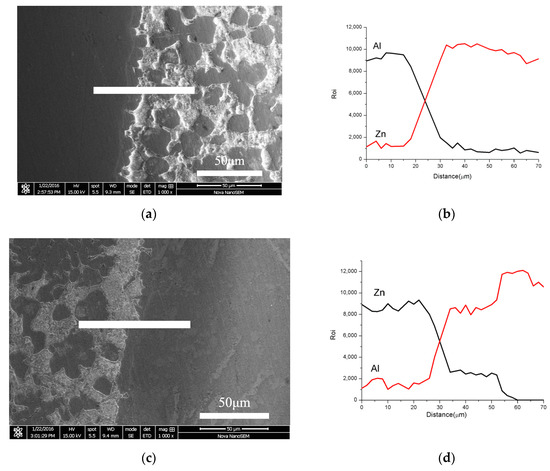
The elemental composition of the interface between the Zn-Al alloy fusion and the substrates of Al sheet and foam core is shown in Figure 4. The main elements across the interface (Al in sheets and foam core, Zn in Zn-Al alloy) are continuous. It indicates that the mutual diffusion of Aluminum and Zinc atoms occurred in the process of metallurgical joining. Figure 4c,d shows that the contents of Zinc atoms and Aluminum atoms change linearly and continuously from the Zinc-rich seam to the Aluminum-rich area within a certain diffusion distance. The molten Zn-10Al alloy has good wettability and diffusion on the surface of the Aluminum substrate during hot-dip coating and metallurgical joining process. The inter-diffusion greatly improves the joining strength.
The surfaces of Al sheet and AF core are pretreated to remove dirt and Aluminum Oxide before fabrication. In the process of hot-dipping, the joint interfaces of AF and Al sheets are in direct contact with the molten Zn-10Al alloy. Al and Zn have high solid solubility to each other at high temperature, which result to obvious mutual diffusion behavior [29,30]. Zn atom diffuse from the alloy to the sheets and core substrates, while Al atom diffuse to the opposite side. The higher the Zn content in the Al interface, the lower the melt point of Al alloy in joint interface. The melting parts of the surface cause the oxide film broken and destroyed. In conclusion, the mutual diffusion of alloy atom and the remove of oxide film promote the combination of alloy coating and lays a good foundation for AFS manufacture.
During the hot press process, the Zinc-based alloy remelt at a high temperature. Since the oxide film on the surface of the substrates is partially removed in the pretreatment, the Zinc atoms have good wettability to the substrates [29]. They easily diffuse into the Aluminum substrate and occupy the position of the oxide film and some Aluminum atoms, which lead to more frequent mutual diffusion. Similar to the hot-dip process, the higher the Zn content in the Al interface, the lower the melt point of Al alloy in the joint interface. Eventually, part of the Aluminum substrate under the oxide film melt. Since the oxide film had a lower density than the alloy, it floated in the molten alloy and separated from the Aluminum substrate. Ultrasound makes the Al foam and Al sheets vibrate to remove the floating oxide film and promote the diffusion effect in the molten area. Former studies [30,31] showed that when ultrasound is applied to a metal melt, it will caused the cavitation effect. The cavitation effect induce mechanical effects such as acoustic flow and shock waves in the metal melt [32,33]. These mechanical effects also can destroy the oxide film and help to achieve completely wetting. Moreover, the mechanical effects caused by the cavitation effect will also play a role similar to stirring [34], eliminating the inclusion of air in the molten Zi-Al alloy. Finally, the fusion area is compact and continuous without any visible defects.
3.2. Peel Strength Test
In order to verify the research of microstructure, peel strength test was carried out to check the joining effects. Three samples from each the two kinds of AFS panels were tested. The results reported in Figure 5 show that the average peel strength of metallurgical joining samples (140.0 N·mm/mm) is higher than the adhesive joining samples (27.5 N·mm/mm) (see Table 1).
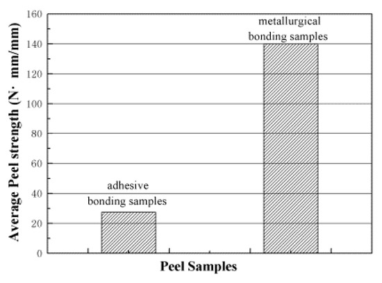
Figure 5.
Average peel strength of two types of samples.

Table 1.
Experimental data for peel strength.
Figure 6 shows the fracture morphology of two types of AFS samples after the peel strength test. For the metallurgical joining AFS, the main destroyed part was not the hot-dip coating but the Al foam core, as shown in Figure 6b. That means the strength of the joint is higher than the Al-foam core. In contrast, for the adhesive ones, the glue film and the sheets were nearly completely detached, which means the strength of the joint is lower than the film itself and the AF core. It may result from the defects made during the heat press process in the adhesive area.
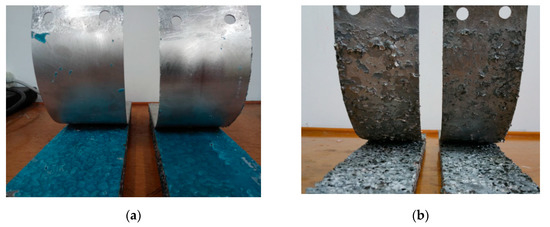
Figure 6.
Appearances of Peel Fractures of two types of samples (a) Adhesive joining samples (b) Metallurgical joining samples.
3.3. Three-Point Bending Fatigue
Figure 7 shows the S-N curves of the two kinds of sandwich panels. Under the same load, the fatigue life of metallurgical joining samples is much longer than the adhesive ones. Harte et al. [35] investigated the AFS four-point fatigue behavior and fitted the S-N curve to predict the fatigue limit. With this method, the S-N curves are fitted with the average fatigue life (three repeated tests for every given load, in Table 2) of every given load to achieve the experience formula of metallurgical joining samples (Equation (1)) and adhesive joining samples (Equation (2)).
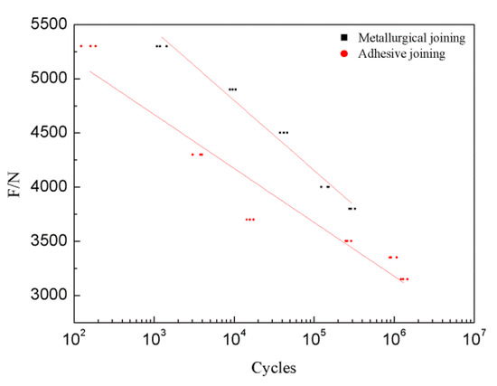
Figure 7.
S-N curves of metallurgical joining and adhesive joining AFS.
Table 2.
Experimental data for three-point bending fatigue.
Since N is cycles, we define the fatigue limit as the force when fatigue life is about 5 million cycles [36]. According to Equations (1) and (2) above, the fatigue limit of metallurgical joining samples is 3058 N, adhesive joining samples is 2829 N (see Table 2). Besides, since it is the estimating limits, for further research more factors should be considered such as the strain degradation of pure foams [37].
The deflection curves of the two kinds of samples for various stress levels are shown in Figure 8. At the beginning, the fatigue response comprised a slow rate of accumulation of deflection with increasing cycles. The defects in the incubation period grew slowly and steadily due to the microdamage development. When microdamage developed to a critical collapsing level, the inner crake rapidly grew and the rate of deflection increased dramatically, which means the end of the incubation period and the coming of failure. Comparing Figure 8a with Figure 8b, the critical collapsing level of the metallurgical joining samples is much higher than the adhesive joining samples at the same loading force. These behaviors above are similar to that noted by Harte et al. [35].
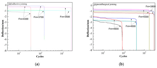
Figure 8.
Deflection versus number of cycles of two kinds of samples (a) adhesive joining samples (b) metallurgical joining samples.
In former studies, Harte et al. [35,38] suggested three types of bending fatigue failure modes for sandwich structure: face fatigue, indentation fatigue and core shear. Face fatigue is manifested the fatigue cracks across the face sheet on the tensile side of the beam. Indentation fatigue appears to be the indentation beneath the loading rollers. In addition, core shear displays the fatigue cracks inclined at an angle of approximately 45° to the neutral axis. In addition, if the face sheets change to higher strength material, such as AISI 304 steel, the AFS panels will fail in only two modes, indentation fatigue and core shear [39].
The fatigue fractures of the two kinds of AFS panels are shown in Figure 9. Since the fatigue cracks are on the tensile side of AFS panels, it is clear that the failure mode of adhesive AFS is debonding and face fatigue, while the failure mode of a metallurgical AFS is face fatigue without debonding. According to the test records, the failure process of adhesive samples can be divided into two stages. First the core and the face sheets debonded, then the Aluminum foam core was broken by the bending force. When debonding occurs, the foam core will loss the protect of face sheet and quickly achieve the collapse load.
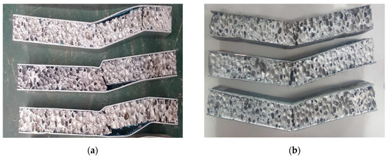
Figure 9.
Fatigue fracture morphology of two types of AFS (a) adhesive joining samples (b) metallurgical joining samples.
For face fatigue, the peak load F is
For Equation (3) [37], b is the AFS width, t is the thickness of face sheet, l is the span length of three-point bending, S is the length between to upper forces in four-point bending fatigue failure, σf is the yield strength of face sheet, σc is the yield strength of core.
While in three-point bending, S can be regarded as zero, so Equation (3) can change to:
When debonding occurs, the face sheets and core are separated, and the peak load will be the smaller one of the two parts in the formula. So we can say that the face sheet debonding lead to a decrease of bending strength. In conclusion, the metallurgical joining did not show the process of debonding, which shows obviously the higher bonding strength.
4. Conclusions
The metallurgical joining of AFS was successfully fabricated via the method of hot-dipping, hot-press process with ultrasonic vibration assisted, Zn-10Al alloy used as a soldering material. The ultrasonic vibration makes the molten solder compact and continuous, and removes the oxide film, which leads to the high strength joint. The average peel strength of metallurgical joining is 140.0 N·mm/mm, which is much higher than the adhesive joining. The metallurgical joining AFS have a much longer fatigue life than the adhesive sample under the same load, and also the fatigue limit of metallurgical joining AFS is much higher than adhesive joining AFS. The fatigue fracture mode for these two types of structure is completely different. The failure mode of the metallurgical joining is face fatigue, while the failure mode for the adhesive sample is face fatigue and debonding. The higher joining strength leads to a fatigue life improved significantly.
Author Contributions
Conceptualization: Z.H.; formal analysis: C.Y.; funding acquisition: Z.H. and F.M.; investigation: C.Y. and Y.W.; methodology: C.Y.; supervision: Z.H. and F.M.; validation, C.Y. and Y.W.; writing—original draft: C.Y.; writing—review and editing: Z.H.
Funding
This research was funded by the National Key Research and Development Program of China (Project No. 2017YFB0103700, 2013BAG19B01).
Conflicts of Interest
The authors declare no conflict of interest.
References
- Ashby, M.F.; Lu, T.J. Metals foam: A survey. Sci. China 2003, 46, 521–532. [Google Scholar] [CrossRef]
- Davies, G.J.; Zhen, S. Metallic foams: their production, properties and applications. J. Mater. Sci. 1983, 18, 1899–1911. [Google Scholar] [CrossRef]
- Alvandi-Tabrizi, Y.; Whisler, D.A.; Kim, H.; Rabiei, A. High strain rate behavior of composite metal foams. Mater. Sci. Eng. 2015, A631, 248–257. [Google Scholar] [CrossRef]
- Gui, M.C.; Wang, D.B.; Wu, J.J.; Yuan, G.J.; Li, C.G. Deformation and damping behaviors of foamed Al-Si-SiCp composite. Mater. Sci. Eng. 2000, A286, 282–288. [Google Scholar] [CrossRef]
- Gibson, L.J.; Ashby, M.F. Cellular Solids: Structure & Properties; Cambridge University Press: Cambridge, UK, 1997; p. 510. [Google Scholar]
- Katona, B.; Szebényi, G.; Orbulov, I.N. Fatigue properties of ceramic hollow sphere filled aluminium matrix syntactic foams. Mater. Sci. Eng. 2017, A679, 350–357. [Google Scholar]
- Katona, B.; Szebényi, A.T.; Orbulov, I.N. Compressive characteristics and low frequency damping of aluminium matrix syntactic foams. Mater. Sci. Eng. 2019, A739, 140–148. [Google Scholar]
- Vendra, L.; Nevile, B.; Rabiel, A. Fatigue in aluminium-steel and steel-steel composite foams. Mater. Sci. Eng. 2009, A517, 146–153. [Google Scholar]
- Banhart, J.; Seeliger, H.W. Aluminium Foam Sandwich Panels: Manufacture, Metallurgy and Applications. Adv. Eng. Mater. 2008, 10, 793–802. [Google Scholar] [CrossRef]
- Garcia-Moreno, F. Commercial Applications of Metal Foams: Their Properties and Production. Materials 2018, 9, 85. [Google Scholar] [CrossRef]
- Crupi, V.; Epasto, G.; Guglielmino, E. Comparison of aluminium sandwiches for lightweight ship structures: Honeycomb vs. foam. Mar. Struct. 2013, 30, 74–96. [Google Scholar] [CrossRef]
- Golovin, I.S.; Sinning, H.R. Damping in some cellular metallic materials. J. Alloys Compd. 2003, 355, 2–9. [Google Scholar] [CrossRef]
- Yang, D.H.; Yang, S.R.; Wang, H.; Ma, A.B.; Jiang, J.H.; Chen, J.Q.; Wang, D.L. Compressive properties of cellular Mg foams fabricated by melt-foaming method. Mater. Sci. Eng. 2010, A527, 5405–5409. [Google Scholar] [CrossRef]
- Huang, Z.; Qin, Z.; Chu, F. Damping mechanism of elastic-viscoelastic-elastic sandwich structures. Compos. Struct. 2016, 153, 96–107. [Google Scholar] [CrossRef]
- Yu, G.C.; Feng, L.J.; Wu, L.Z. Thermal and mechanical properties of a multifunctional composite square honeycomb sandwich structure. Mater. Des. 2016, 102, 238–246. [Google Scholar] [CrossRef]
- Harte, A.M.; Fleck, N.A.; Ashby, M.F. Sandwich panel design using Aluminum alloy foam. Adv. Eng. Mater. 2000, 2, 219–222. [Google Scholar] [CrossRef]
- Hangai, Y.; Takahashi, K.; Yamaguchi, R.; Utsunomiya, T.; Kitahara, S.; Kuwazuru, O.; Yoshikawa, N. Nondestructive observation of pore structure deformation behavior of functionally graded Aluminum foam by X-ray computed tomography. Mater. Sci. Eng. 2012, A556, 678–684. [Google Scholar] [CrossRef]
- Chen, N.; Feng, Y.; Chen, J.; Li, B.; Chen, F.; Zhao, J. Vacuum Brazing Processes of Aluminum Foam. Rare Metal Mater. Eng. 2013, 42, 1118–1122. [Google Scholar]
- Matsumoto, R.; Tsuruoka, H.; Otsu, M.; Utsunomiya, H. Fabrication of skin layer on Aluminum foam surface by friction stir incremental forming and its mechanical properties. J. Mater. Process. Technol. 2015, 218, 23–31. [Google Scholar] [CrossRef]
- D’Urso, G.; Maccarini, G. The formability of Aluminum Foam Sandwich panels. Int. J. Mater. Form. 2012, 5, 243–257. [Google Scholar] [CrossRef]
- Olurin, O.B.; Fleck, N.A.; Ashby, M.F. Joining of Aluminum foam with fasteners and adhesives. J. Mater. Sci. 2000, 35, 1079–1085. [Google Scholar] [CrossRef]
- Deshpande, V.S.; Fleck, N.A. High strain rate compressive behaviour of aluminium alloy foams. Int. J. Imapct Eng. 2000, 24, 277–298. [Google Scholar] [CrossRef]
- Jitai, N. Joining of Aluminium Alloy Sheets to Aluminium Alloy Foam Using Metal Glasses. Metals 2018, 8, 614. [Google Scholar]
- Duarte, I.; Krstulović-Opara, L.; Vesenjak, M. Axial crush behaviour of the aluminium alloy in-situ foam filled tubes with very low wall thickness. Compos. Struct. 2018, 192, 184–192. [Google Scholar] [CrossRef]
- Kitazono, K.; Kitajima, A.; Sato, E.; Matsushita, J.; Kuribayashi, K. Solid-state diffusion bonding of closed-cell Aluminum foams. Mater. Sci. Eng. 2002, A237, 128–132. [Google Scholar] [CrossRef]
- Ubertalli, G.; Ferrais, M.; Bangash, M.K. Joining of AL-6016 to Al-foam using Zn-based joining materials. Compsites Part A 2017, 96, 122–128. [Google Scholar] [CrossRef]
- ASTM_C393-C393M-06, Standard Test Method for Core Shear Properties of Sandwich Constructions by Beam Flexu-re; ASTM International: West Conshohocken, PA, America, 2006.
- GB/T 1457-2005, Test Method for Climbing Drum Peel Strength of Sandwich Constructions; Standards Press of China: Beijing, China, 2005.
- Wang, H.; Yang, D.; He, S.; He, D. Fabrication of open-cell Al foam core sandwich by vibration aided liquid phase bonding method and its mechanical properties. J. Mater. Sci. Technol. 2010, 26, 423–428. [Google Scholar] [CrossRef]
- Wan, L.; Huang, Y.; Lv, S.; Feng, J. Fabrication and interfacial characterization of Aluminum Foam Sandwich via fluxless soldering with surface abrasion. Compos. Struct. 2015, 123, 366–373. [Google Scholar] [CrossRef]
- Kotadia, H.R.; Das, A. Modification of solidification microstructure in hypo- and hyper-eutectic Al–Si alloys under high-intensity ultrasonic irradiation. Mater. Chem. Phys. 2011, 125, 853–859. [Google Scholar] [CrossRef]
- Xu, Z.; Yan, J.; Zhang, B.; Kong, X.; Yang, S. Behaviors of Oxide film at the ultrasonic aided interaction interface of Zn-Al alloy and Al2O3p/6061Al composites in air. Mater. Sci. Eng. 2006, A415, 80–86. [Google Scholar] [CrossRef]
- Zhang, S.; Zhao, Y.; Cheng, X.; Chen, G.; Dai, Q. High-energy ultrasonic field effects on the microstructure and mechanical behaviors of A356 alloy. J. Alloys Compd. 2009, 470, 168–172. [Google Scholar] [CrossRef]
- Zheng, D.; Chen, R.; Ma, T.; Ding, H.; Su, Y.; Guo, J.; Fu, H. Microstructure modification and mechanical performances enhancement of Ti44Al6Nb1 Cr alloy by ultrasound treatment. J. Alloys Compd. 2017, 710, 409–417. [Google Scholar] [CrossRef]
- Harte, A.M.; Fleck, N.A.; Ashby, M.F. The fatigue strength of sandwich beams with an aluminium alloy foam core. Int. J. Fatigue 2001, 23, 499–507. [Google Scholar] [CrossRef]
- Burman, M.; Zenkert, D. Fatigue of foam core sandwich beams—1: undamaged specimens. Int. J. Fatigue 1997, 19, 551–561. [Google Scholar] [CrossRef]
- Linul, E.; Serban, D.A.; Marsavina, L.; Kovacik, J. Low-cycle fatigue behaviour of ductile closed-cell aluminium alloy foams. Fatigue Fract. Eng. Mater. Struct. 2017, 40, 597–604. [Google Scholar] [CrossRef]
- Chen, C.; Harte, A.M.; Fleck, N.A. The plastic collapse of sandwich beams with a metallic foam. Int. J. Mech. Sci. 2001, 43, 1483–1506. [Google Scholar] [CrossRef]
- Duart, I.; Teixeir-Dias, F.; Graça, A.; Ferreira, A.J.M. Failure Modes and Influence of the Quasi-static Deformation Rate on the Mechanical Behavior of Sandwich Panels with Aluminum Foam Cores. Mech. Adv. Mater. Struct. 2010, 17, 335–342. [Google Scholar] [CrossRef]


© 2019 by the authors. Licensee MDPI, Basel, Switzerland. This article is an open access article distributed under the terms and conditions of the Creative Commons Attribution (CC BY) license (http://creativecommons.org/licenses/by/4.0/).